EP3658882B1 - Dispositif, système et procédé de détermination de l'état d'un composant mécanique - Google Patents
Dispositif, système et procédé de détermination de l'état d'un composant mécanique Download PDFInfo
- Publication number
- EP3658882B1 EP3658882B1 EP18743471.7A EP18743471A EP3658882B1 EP 3658882 B1 EP3658882 B1 EP 3658882B1 EP 18743471 A EP18743471 A EP 18743471A EP 3658882 B1 EP3658882 B1 EP 3658882B1
- Authority
- EP
- European Patent Office
- Prior art keywords
- component
- mechanical component
- voltage
- state
- bearing
- Prior art date
- Legal status (The legal status is an assumption and is not a legal conclusion. Google has not performed a legal analysis and makes no representation as to the accuracy of the status listed.)
- Active
Links
Images


Classifications
-
- G—PHYSICS
- G01—MEASURING; TESTING
- G01M—TESTING STATIC OR DYNAMIC BALANCE OF MACHINES OR STRUCTURES; TESTING OF STRUCTURES OR APPARATUS, NOT OTHERWISE PROVIDED FOR
- G01M13/00—Testing of machine parts
- G01M13/04—Bearings
-
- G—PHYSICS
- G01—MEASURING; TESTING
- G01R—MEASURING ELECTRIC VARIABLES; MEASURING MAGNETIC VARIABLES
- G01R19/00—Arrangements for measuring currents or voltages or for indicating presence or sign thereof
- G01R19/0084—Measuring voltage only
-
- G—PHYSICS
- G05—CONTROLLING; REGULATING
- G05B—CONTROL OR REGULATING SYSTEMS IN GENERAL; FUNCTIONAL ELEMENTS OF SUCH SYSTEMS; MONITORING OR TESTING ARRANGEMENTS FOR SUCH SYSTEMS OR ELEMENTS
- G05B23/00—Testing or monitoring of control systems or parts thereof
- G05B23/02—Electric testing or monitoring
- G05B23/0205—Electric testing or monitoring by means of a monitoring system capable of detecting and responding to faults
- G05B23/0259—Electric testing or monitoring by means of a monitoring system capable of detecting and responding to faults characterized by the response to fault detection
- G05B23/0275—Fault isolation and identification, e.g. classify fault; estimate cause or root of failure
- G05B23/0281—Quantitative, e.g. mathematical distance; Clustering; Neural networks; Statistical analysis
Definitions
- the invention relates to a device for determining the state of a mechanical component, in which at least part of the component is moved relative to another component when the component is in use.
- the invention further relates to a system and a method for determining the condition of a mechanical component.
- the mechanical component has the lubrication specified in its design and construction, in particular with regard to the location where the lubrication should be located, as well as with regard to the quality of the lubrication used Lubricant, but also with regard to the amount of lubricant to be provided.
- the mechanical component when operating mechanical components, it is of interest whether the mechanical component requires the lubrication specified in its design and construction, in particular with regard to the location where the lubrication should be located, as well as with regard to the quality of the lubricant used, but also with regard to the quantity of the lubricant to be provided.
- WO 2006/134068 A1 discloses an arrangement and a method for bearing current monitoring of an electric motor.
- US 5,936,410 A discloses a hydrodynamic bearing with means for monitoring the capacity between the rotor and the stator of the hydrodynamic bearing.
- WO 2008/000285 A1 discloses a method for indicating fatigue damage to a metallic object.
- the invention was based on the object of proposing a device as well as a system and a method for determining the state of a mechanical component, in which at least part of the component is moved relative to another component when the component is in use, which in particular can be carried out easily.
- the invention is based on the basic idea of determining the state of a mechanical component, in which at least part of the component is moved relative to another component when the component is in use, not using mechanical measuring methods, but rather by determining an electrical quantity or by Determination of a change in an electrical quantity, which according to the invention is an electrical voltage.
- the invention has recognized that a voltage that is determined on the mechanical component can provide information about the condition of the mechanical component.
- looking at the rate of change can provide information about the condition of the mechanical component, i.e. the knowledge that, for example, the impedance changes at a first rate in a first observation period and at a second rate in a second observation period.
- the invention in particular as a state of the mechanical component, in which at least part of the component is moved relative to another component when the component is in use, it can be determined whether the component is lubricated and what degree of lubrication (in particular the change in the thickness of the lubricant film) is present and what quality (in particular what aging condition) the lubricant has.
- the invention offers, for example, the possibility of early evaluation of the lubricant quality in a bearing or in a drive train. This is important because many bearing defects occur due to insufficient lubrication.
- the invention also allows analysis of very slowly rotating bearings, which can hardly be analyzed using vibration analysis, for example.
- the invention allows the early detection of the condition of the bearing or the gearbox or the drive train or mechanical damage to these.
- the state of the movable mechanical component can be determined as to whether there is mechanical damage on or in the component, i.e. whether there are deviations from the shape of the parts of the component determined during the design and construction of the mechanical component.
- the dimensional accuracy of parts of the mechanical component can also be checked. Deviations in material qualities can also be detected, namely those that have an influence on electrical conductivity.
- the electrical voltage applied to the component is determined as the electrical variable to be determined or as the electrical variable whose change is determined according to the invention.
- the device according to the invention for determining the state of a mechanical component, which is a bearing has a measuring device which is designed as a voltmeter.
- the measurement signals are usually evaluated using a microprocessor.
- the device according to the invention has an evaluation unit which, based on a measurement result generated by the measuring device, provides status information about the condition of the mechanical component, in which at least one Part of the component is moved relative to another component.
- an evaluation unit which, based on a measurement result generated by the measuring device, provides status information about the condition of the mechanical component, in which at least one Part of the component is moved relative to another component.
- a signal line between the measuring device and the evaluation unit, along which an electrical or an optical signal can particularly preferably be exchanged between the measuring device and the evaluation unit.
- a size of the signal for example its strength or its time course, is particularly preferably dependent on a characteristic size of the voltage determined by the measuring device or the change in the voltage.
- the output of the status information can be very simplified, for example it can be provided that the evaluation unit emits status information in the form of a visual stimulus (for example a red light turns on) or a tone when a certain, undesired status is reached, while the absence of one optical stimulus or a sound is the information that the state of the mechanical component, in which at least part of the component is moved relative to another component when the component is in use, has not yet reached the undesirable state. It is also conceivable that the status information is released gradually, for example according to a traffic light system.
- a visual stimulus for example a red light turns on
- a tone when a certain, undesired status is reached
- the absence of one optical stimulus or a sound is the information that the state of the mechanical component, in which at least part of the component is moved relative to another component when the component is in use, has not yet reached the undesirable state.
- the status information is released gradually, for example according to a traffic light system.
- the invention can be used to make concrete statements about the state of the mechanical component, in which at least part of the component is moved relative to another component when the component is in use, for example after how many additional hours of operation of the mechanical component, in which at least part of the component is moved relative to another component during use of the component, the failure of a specific component is to be expected.
- a table is stored in the evaluation unit, in which respective status information about the condition of the mechanical component is assigned to a respective measurement result of the measuring device.
- the evaluation unit therefore works with a “look up table”. Empirical values can be entered in this table, which can be determined using simple test bench tests.
- the device according to the invention has a voltage source as a signal generator with which a voltage can be applied to the motor shaft via a mechanical component. In order to determine certain voltages or to determine certain changes in voltage, it is necessary to apply a voltage to the motor shaft via the mechanical component. By equipping the device with a voltage source, the device according to the invention becomes self-sufficient.
- the device according to the invention is designed to introduce an input signal on the motor shaft into the mechanical component.
- the measuring device can be designed in such a way that it can measure a voltage across the mechanical component over a predetermined measuring period. It is particularly preferred in this embodiment that an evaluation unit is provided which has a module for evaluating the course of the measured voltage using a multivariate statistical method during the measurement period, with status information about the status of the movable mechanical component being output from the evaluation.
- the observed mechanical component is a bearing.
- the system according to the invention has the mechanical component and a device according to the invention.
- the system according to the invention describes, on the one hand, the state when, for example for an individual measurement of the state of the mechanical component, the device according to the invention is connected to the mechanical component in such a way that the measuring device of the device according to the invention measures the voltage or the change in voltage on the mechanical component can determine.
- the system according to the invention allows the device according to the invention to be separated from the mechanical component and the system according to the invention therefore only exists for a short time (during the measurement).
- the system claim according to the invention includes integrated units made up of the mechanical component and the device according to the invention. So for example, the invention can be used very well for onboard diagnostic systems, for example in vehicles, in particular in rail vehicles or road vehicles, in particular motor vehicles or, for example, in production systems, such as rolling mills.
- the method according to the invention provides that a voltage or the change in a voltage on the mechanical component is determined using a measuring device.
- a voltage is applied to the motor shaft using a voltage source and the voltage difference between the stator and earth is determined using a measuring device, which is a voltmeter that is designed to be coupled to the motor shaft.
- the evaluation unit can be used to evaluate the course of the measured voltage during the measurement period using a multivariate statistical method, with the evaluation unit outputting status information about the status of the movable mechanical component from the evaluation.
- This embodiment is based on the knowledge that status information about the state of the movable mechanical component can not only be obtained from the level of a voltage measured at a certain point in time, but also, for example, from an evaluation of the voltage curve using a multivariate statistical method via a predetermined one Measuring period condition information about the condition of the movable mechanical component can be obtained.
- the statistical evaluation includes determining the frequency distribution of individual voltages over the predetermined measurement period. For example, as a result of the statistical evaluation, a histogram can be generated that shows which voltage was present and how often within the predetermined measurement period. For simplicity and reasons of clarity, the histogram can summarize voltages into voltage ranges in the bars shown in it; The histogram bar then shows how often a voltage from this voltage range was present.
- the evaluation unit compares the result of the evaluation using a multivariate statistical method of the voltage curve over a predetermined measurement period with the result of the evaluation using a multivariate statistical method of the voltage curve over a measurement period of the same length but earlier.
- This embodiment is based on the knowledge that the voltage curve changes over a measurement period of a predetermined length depending on the condition of the component. It is therefore possible to compare the result of the evaluation with a multivariate statistical method of the voltage curve over a first measurement period with the result of the evaluation to determine a change in state of the component using a multivariate statistical method of the voltage curve over a second measurement period that is of the same length as the first measurement period.
- the multivariate statistical method is in particular a statistical method.
- a part of the mechanical component to be examined moves relative to another part of the mechanical component to be examined.
- the method according to the invention can be successfully carried out on a stationary component.
- the input signal is constant.
- the input signal varies over time, in particular has a sinusoidal shape or a pulse shape.
- the input signal is a pulse, in particular a delta pulse, for determining the electrical properties of the component.
- the input signal can be pulsed voltage functions, such as a square wave pulse, a triangle pulse or a sawtooth pulse. Good results can be achieved with a pulse-shaped voltage function with at least one steep signal edge, preferably with a steep input edge and a steep output edge.
- the fundamental frequency of the signal can also be used to achieve good results. Depending on the movement status of the component to be examined, these two parameters enable useful information to be obtained through their deviations from the reference signal and thereby determine the condition of the mechanical component.
- the mechanical properties of the component are determined by determining an electrical quantity by carrying out a reference measurement, after which the actual measurement is then carried out.
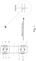
- Fig. 1 shows a cross section of part of a ball bearing. You can see the outer ring 1, the inner ring 2 and a ball 3 of the ball bearing. Furthermore, the seals 4 attached to the sides can be seen. Also shown is the lubricant 14 present between the outer ring 1 and the ball 3 and the lubricant 14 present between the inner ring 2 and the ball 3. For clarity, undesirable interference currents 15 are also shown, which flow from the inner ring 2 via the lubricant to the ball 3 and flow from the ball 3 via the lubricant 14 to the outer ring 1. Such unwanted currents 15 are often referred to as bearing currents. Fig. 1 also illustrates the electrical equivalent of the ball bearing components highlighted in the dashed circle.
- the Fig. 2 shows an experimental setup that was used to demonstrate the effectiveness of the invention.
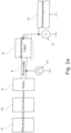
- the Fig. 2a shows schematically the structure of a bearing test bench as an embodiment.
- the mechanical component 5 is a ball bearing that supports a rotor 7 driven by a motor shaft 6 in a stator 12.
- the motor shaft 6 is connected to a motor 8, which is powered by a power source 9 and a converter 10 connected downstream of the power source 9.
- a voltage signal is coupled into the motor shaft 6 by means of a signal generator 17.
- a voltmeter is used as the measuring device 11, which is coupled to the stator 12 and determines the voltage difference between the stator 12 and, for example, earth (ground). The determined voltage is recorded in an evaluation unit 13 in the time domain.
- the evaluation unit 13 calculates a histogram from the time-related voltage curves (cf. Fig. 5 , Fig. 6 ). The determination of the bearing condition results from the distribution of the histogram.
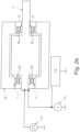
- the Fig. 2b it can be seen that two ball bearings are used as mechanical components 5 to support the rotor. The state of the ball bearings can be determined by determining the voltage difference between the stator 12 and earth (ground) as an electrical variable. As in Fig. 2a the determined voltage is recorded by an evaluation unit 13 in the time domain. The evaluation unit 13 calculates a histogram from the time-related voltage curves (cf. Fig. 5 , Fig. 6 ). The determination of the bearing condition results from the distribution of the histogram.
- Two operating states were considered, namely the standstill of the ball bearings as a reference and a short period of time in the braking phase (reduction in speed) at 10% of the maximum speed of the motor/bearing.
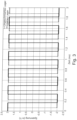
- the Y-axis represents the voltage
- the X-axis represents the time
- the Y-axis represents the frequency of the voltage ranges
- the X-axis represents the existing voltage ranges.
- the Fig. 3 shows the voltage curves of the reference voltage at the two bearings over time at standstill.
- the phase shift is irrelevant here because the tests were carried out one after the other. However, it can be seen that there is no difference in amplitude between the two bearings when stationary. This is also to be expected when the bearing is at a standstill, as no significant lubricant film forms in the bearing when the bearing is at a standstill.
- the DC voltage difference between the reference voltages was 8.9mV at standstill.
- the Fig. 4 shows the voltage curves of the two bearings over time during the braking phase at 10% of the maximum speed.
- the voltage curves of the two curves show transient processes that are caused by the rotational movement of the bearings. While the stress curve in the unlubricated bearing is almost symmetrical remains metric, the voltage amplitude of the intact bearing shifts downwards by more than 800mV. The DC voltage difference between the bearings was 932mV in this section of the braking phase.
- the Fig. 5 shows the frequency of the voltage ranges on the two bearings at standstill. It can be seen that all existing voltage ranges are concentrated at the maximum amplitudes of the reference voltage and there are no significant voltage spreads in other areas.
- the Fig. 6 shows the histogram of the frequencies of the voltage ranges on the two bearings in the operating state with 10% of the maximum speed (a short section in the braking phase).
- the ones in the Fig. 6 The vertical dashed lines shown represent the amplitude of the reference voltages.
- the vertical solid or dotted lines represent the center of the stress distributions for both bearings.
- the black and white arrows show the displacement magnitude and direction of displacement from the amplitude of the reference voltage.
- the investigations show that the condition of a mechanical component can be determined by looking at the voltage.
Landscapes
- Physics & Mathematics (AREA)
- General Physics & Mathematics (AREA)
- Engineering & Computer Science (AREA)
- Mathematical Analysis (AREA)
- Artificial Intelligence (AREA)
- Evolutionary Computation (AREA)
- Algebra (AREA)
- Mathematical Optimization (AREA)
- Mathematical Physics (AREA)
- Probability & Statistics with Applications (AREA)
- Pure & Applied Mathematics (AREA)
- Automation & Control Theory (AREA)
- Testing Of Devices, Machine Parts, Or Other Structures Thereof (AREA)
- Rolling Contact Bearings (AREA)
Claims (4)
- Dispositif de détermination de l'état d'un composant mécanique (5), qui est un palier supportant un rotor (7) entraîné par un arbre de moteur (6) dans un stator (12), dans lequel, lors de l'utilisation du composant, au moins une partie du composant est déplacée par rapport à un autre composant, un dispositif de mesure (11), qui peut déterminer une grandeur électrique du composant mécanique (5) ou la variation d'une grandeur électrique, et une unité d'évaluation (13), qui, sur la base d'un résultat de mesure généré par le dispositif de mesure (11), émet une information d'état sur l'état du composant mécanique mobile (5), caractérisé en ce qu'un générateur de signaux (17) est prévu et conçu pour injecter un signal de tension sur l'arbre moteur (6), et le dispositif de mesure (11) est un voltmètre et conçu pour être couplé au stator (12) et pour déterminer la différence de tension entre le stator (12) et la masse.
- Dispositif selon la revendication 1, caractérisé par un tableau stocké dans l'unité d'évaluation (13), dans lequel une information d'état respective concernant l'état du composant mécanique mobile (5) est associée à un résultat de mesure respectif du dispositif de mesure (11).
- Système composé du composant mécanique (5) et d'un dispositif selon l'une des revendications 1 à 2.
- Procédé de détermination de l'état d'un composant mécanique (5) qui est un palier supportant un rotor (7) entraîné par un arbre de moteur (6) dans un stator (12), une grandeur électrique ou la variation d'une grandeur électrique sur le composant mécanique (5) étant déterminée au moyen d'un dispositif de mesure (11), une unité d'évaluation (13) émettant, sur la base d'un résultat de mesure généré par le dispositif de mesure (11), une information d'état sur l'état du composant mécanique mobile (5), caractérisé en ce qu'un signal de tension généré au moyen d'un générateur de signaux (17) est injecté sur l'arbre moteur (6), et le dispositif de mesure (11) est un voltmètre qui est couplé au stator (12) et détermine la différence de tension entre le stator (12) et la masse.
Priority Applications (1)
| Application Number | Priority Date | Filing Date | Title |
|---|---|---|---|
| EP23199034.2A EP4283317B1 (fr) | 2017-07-24 | 2018-07-18 | Dispositif, système et procédé de détermination de l'état d'un composant mécanique |
Applications Claiming Priority (2)
| Application Number | Priority Date | Filing Date | Title |
|---|---|---|---|
| DE102017212666.3A DE102017212666B4 (de) | 2017-07-24 | 2017-07-24 | Verfahren und Vorrichtung zur Bestimmung des Zustands eines mechanischen Bauteils |
| PCT/EP2018/069562 WO2019020473A1 (fr) | 2017-07-24 | 2018-07-18 | Dispositif de détermination de l'état d'un composant mécanique, utilisation d'un dispositif de mesure, système et procédé de détermination de l'état d'un composant mécanique |
Related Child Applications (2)
| Application Number | Title | Priority Date | Filing Date |
|---|---|---|---|
| EP23199034.2A Division-Into EP4283317B1 (fr) | 2017-07-24 | 2018-07-18 | Dispositif, système et procédé de détermination de l'état d'un composant mécanique |
| EP23199034.2A Division EP4283317B1 (fr) | 2017-07-24 | 2018-07-18 | Dispositif, système et procédé de détermination de l'état d'un composant mécanique |
Publications (2)
| Publication Number | Publication Date |
|---|---|
| EP3658882A1 EP3658882A1 (fr) | 2020-06-03 |
| EP3658882B1 true EP3658882B1 (fr) | 2024-01-03 |
Family
ID=62981215
Family Applications (2)
| Application Number | Title | Priority Date | Filing Date |
|---|---|---|---|
| EP23199034.2A Active EP4283317B1 (fr) | 2017-07-24 | 2018-07-18 | Dispositif, système et procédé de détermination de l'état d'un composant mécanique |
| EP18743471.7A Active EP3658882B1 (fr) | 2017-07-24 | 2018-07-18 | Dispositif, système et procédé de détermination de l'état d'un composant mécanique |
Family Applications Before (1)
| Application Number | Title | Priority Date | Filing Date |
|---|---|---|---|
| EP23199034.2A Active EP4283317B1 (fr) | 2017-07-24 | 2018-07-18 | Dispositif, système et procédé de détermination de l'état d'un composant mécanique |
Country Status (7)
| Country | Link |
|---|---|
| US (1) | US11371910B2 (fr) |
| EP (2) | EP4283317B1 (fr) |
| JP (1) | JP7791648B2 (fr) |
| CN (1) | CN110959108B (fr) |
| DE (1) | DE102017212666B4 (fr) |
| ES (1) | ES2970613T3 (fr) |
| WO (1) | WO2019020473A1 (fr) |
Families Citing this family (3)
| Publication number | Priority date | Publication date | Assignee | Title |
|---|---|---|---|---|
| DE102019117879A1 (de) * | 2019-07-02 | 2021-01-07 | Dr. E. Horn GmbH & Co. KG | Verfahren und Sensor zur Überwachung eines Zustandes eines Ensembles aus zumindest einem ersten Bauteil in einem zweiten Bauteil |
| JP7460030B2 (ja) * | 2021-08-12 | 2024-04-02 | 三菱電機ビルソリューションズ株式会社 | 軸受けの検査方法 |
| DE102021125852A1 (de) | 2021-10-05 | 2023-04-06 | HCP Sense GmbH | Verfahren zum Bestimmen einer Ausdehnung eines Schadens in einem Lager |
Citations (1)
| Publication number | Priority date | Publication date | Assignee | Title |
|---|---|---|---|---|
| US20150355075A1 (en) * | 2014-06-05 | 2015-12-10 | Aktiebolaget Skf | Rolling bearing and sensor assembly including the same |
Family Cites Families (29)
| Publication number | Priority date | Publication date | Assignee | Title |
|---|---|---|---|---|
| DE825178C (de) * | 1950-01-12 | 1951-12-17 | Hugo Kibele | Verfahren zum Anzeigen der Lagerreibung waehrend des Betriebes einer Maschine |
| JPS5741740Y2 (fr) * | 1977-11-04 | 1982-09-13 | ||
| DE3338420C2 (de) | 1983-10-22 | 1985-11-07 | Schaller-Automation Industrielle Automationstechnik KG, 6653 Blieskastel | Verfahren zur Überwachung von Schmierstellen |
| JPS63105068U (fr) * | 1986-12-24 | 1988-07-07 | ||
| JPH06100442B2 (ja) * | 1990-02-19 | 1994-12-12 | 株式会社前川製作所 | 密閉式回転機械の回転軸部摩耗検出装置 |
| JPH06510116A (ja) * | 1991-04-17 | 1994-11-10 | ベミス・マニファクチュアリング・カンパニー | データ点解析の方法及び装置 |
| GB2336407B (en) | 1997-01-24 | 2000-11-15 | Seagate Technology | Hydrodynamic bearing including means for monitoring the capacitance between the rotor and stator of hydrodynamic bearing |
| JP3988363B2 (ja) * | 2000-07-13 | 2007-10-10 | 株式会社ジェイテクト | 動圧軸受の評価方法 |
| JP2002131188A (ja) | 2000-10-20 | 2002-05-09 | Sankyo Seiki Mfg Co Ltd | モータ軸受監視装置および記憶装置 |
| JP4674395B2 (ja) | 2000-10-20 | 2011-04-20 | 日本電産株式会社 | 軸受検査方法 |
| CH697582B1 (de) * | 2004-03-09 | 2008-12-15 | Schaller Automation | Verfahren und Einrichtung zur Steuerung der Zufuhr von Schmiermittel zur Zylinderlauffläche eines Kolbens eines Hubkolbenmotors. |
| DE102004056996A1 (de) * | 2004-11-25 | 2006-06-01 | Siemens Ag | Maschinenanordnung mit einer Maschine, die einen Grundkörper und einen Zusatzkörper aufweist |
| DE102005027670A1 (de) * | 2005-06-15 | 2007-01-11 | Siemens Ag | Anordnung und Verfahren zur Lagerstromüberwachung eines Elektromotors |
| JP4902389B2 (ja) * | 2006-03-28 | 2012-03-21 | アルファナテクノロジー株式会社 | 軸受検査方法及びモータの製造方法 |
| US8479587B2 (en) | 2006-06-28 | 2013-07-09 | Aktiebolaget Skf | Method for indicating fatigue damage of a metal object |
| JP4942496B2 (ja) * | 2007-01-26 | 2012-05-30 | Ntn株式会社 | 軸受状態検査装置および軸受状態検査方法 |
| JP2007298527A (ja) * | 2007-07-06 | 2007-11-15 | Nsk Ltd | 主軸支持装置 |
| FI20080438A0 (fi) | 2008-07-15 | 2008-07-15 | Abb Oy | Menetelmä ja laitteisto laakerivirtojen mittaamiseksi sähkökoneessa |
| DE102010002296A1 (de) | 2010-02-24 | 2011-08-25 | Siemens Aktiengesellschaft, 80333 | Auswertungsverfahren für Lichtbogenentladungen und zugehöriger Prüfstand |
| DE102010002294A1 (de) | 2010-02-24 | 2011-08-25 | Siemens Aktiengesellschaft, 80333 | System bzw. Verfahren zur Ermittlung eines Lagerzustandes |
| DE102010002297A1 (de) | 2010-02-24 | 2011-08-25 | Siemens Aktiengesellschaft, 80333 | Verfahren und Vorrichtung zur Bewertung der Schädigung von Wälzlagern, insbesondere an umrichtergespeisten elektrischen Maschinen |
| JP5143194B2 (ja) * | 2010-07-16 | 2013-02-13 | 中国電力株式会社 | ベアリング診断方法 |
| EP2484900B1 (fr) * | 2011-02-08 | 2017-03-29 | Siemens Aktiengesellschaft | Procédé de lubrification d'au moins un roulement de pale d'éolienne |
| JP6088357B2 (ja) | 2013-05-22 | 2017-03-01 | ファナック株式会社 | モータ軸受の電食の度合いを推定するモータ制御装置、およびその方法 |
| WO2015043619A1 (fr) | 2013-09-24 | 2015-04-02 | Siemens Aktiengesellschaft | Procédé et dispositif de surveillance d'état d'un système de propulsion comprenant un groupe moteur électrique |
| FR3015684B1 (fr) * | 2013-12-20 | 2017-03-03 | Skf Aerospace France | Dispositif de mesure de l'usure d'une rotule, rotule integrant ce dispositif et methode de mesure de l'usure d'une telle rotule |
| JP2016024090A (ja) * | 2014-07-22 | 2016-02-08 | 日本精工株式会社 | 亀裂検知方法 |
| US9689777B2 (en) * | 2015-05-04 | 2017-06-27 | Deere & Company | Fault detection for bearings |
| JP6330864B2 (ja) * | 2015-08-05 | 2018-05-30 | Jfeスチール株式会社 | モータの監視装置および方法 |
-
2017
- 2017-07-24 DE DE102017212666.3A patent/DE102017212666B4/de active Active
-
2018
- 2018-07-18 WO PCT/EP2018/069562 patent/WO2019020473A1/fr not_active Ceased
- 2018-07-18 EP EP23199034.2A patent/EP4283317B1/fr active Active
- 2018-07-18 CN CN201880049678.5A patent/CN110959108B/zh active Active
- 2018-07-18 JP JP2020503279A patent/JP7791648B2/ja active Active
- 2018-07-18 EP EP18743471.7A patent/EP3658882B1/fr active Active
- 2018-07-18 ES ES18743471T patent/ES2970613T3/es active Active
- 2018-07-18 US US16/632,798 patent/US11371910B2/en active Active
Patent Citations (1)
| Publication number | Priority date | Publication date | Assignee | Title |
|---|---|---|---|---|
| US20150355075A1 (en) * | 2014-06-05 | 2015-12-10 | Aktiebolaget Skf | Rolling bearing and sensor assembly including the same |
Also Published As
| Publication number | Publication date |
|---|---|
| JP2020528146A (ja) | 2020-09-17 |
| DE102017212666B4 (de) | 2023-03-02 |
| WO2019020473A1 (fr) | 2019-01-31 |
| JP7791648B2 (ja) | 2025-12-24 |
| EP3658882A1 (fr) | 2020-06-03 |
| CN110959108B (zh) | 2023-01-24 |
| EP4283317A2 (fr) | 2023-11-29 |
| ES2970613T3 (es) | 2024-05-29 |
| US20210131912A1 (en) | 2021-05-06 |
| EP4283317B1 (fr) | 2024-12-25 |
| US11371910B2 (en) | 2022-06-28 |
| EP4283317C0 (fr) | 2024-12-25 |
| EP4283317A3 (fr) | 2023-12-06 |
| DE102017212666A1 (de) | 2019-01-24 |
| CN110959108A (zh) | 2020-04-03 |
Similar Documents
| Publication | Publication Date | Title |
|---|---|---|
| EP2359106B1 (fr) | Procédé et dispositif d'analyse des vibrations, banque de données de motifs à cet effet et utilisation d'une banque de données de motifs | |
| EP1537390B1 (fr) | Procede pour saisir des oscillations de la ligne d'arbres d'une machine electrique | |
| EP3658882B1 (fr) | Dispositif, système et procédé de détermination de l'état d'un composant mécanique | |
| DE102016102328A1 (de) | System zur Diagnose von Anomalien, Diagnoseverfahren und -vorrichtung | |
| EP1197415B1 (fr) | Procédé et dispositif de détection d'un palier à roulement défectueux d'un véhicule ferroviaire | |
| DE19917541A1 (de) | Verfahren und Vorrichtung zur Fehlerdiagnose | |
| DE102016222660A1 (de) | Verfahren und Vorrichtung zum Erkennen von Veränderungen in einem elektrisch betriebenen Antrieb | |
| DE19702234A1 (de) | Verfahren zur Überwachung und Qualitätsbeurteilung von sich bewegenden und/oder rotierenden Maschinenteilen insbesondere von Maschinenlagern | |
| EP3497401A1 (fr) | Procédé permettant de mesurer un espace de lubrification entre des éléments de contact lubrifiés | |
| DE69823937T2 (de) | Verfahren und Vorrichtung zur Bestimmung von Schwingungen des Rotors einer drehenden Maschine | |
| DE102016212887B4 (de) | Messanordnung für Schmieröl und Messverfahren | |
| DE102009024981A1 (de) | Verfahren zur Ermittlung und Analyse von Schäden an umlaufenden Maschinenelementen | |
| DE102015210911A1 (de) | Verfahren und Vorrichtung zum Erkennen von Veränderungen in einem elektrisch betriebenen Antrieb | |
| EP2378145A2 (fr) | Procédé de surveillance d'un guidage linéaire | |
| EP2378146A2 (fr) | Procédé de surveillance d'un guidage linéaire | |
| WO2019086160A1 (fr) | Procédé de surveillance de l'état d'une installation de fabrication | |
| WO2008019654A1 (fr) | Procédé destiné à surveiller un procédé de fabrication | |
| EP3966542B1 (fr) | Procédé et banc d'essai de prédiction des oscillations de pression dans un pneu de véhicule | |
| WO2023041219A1 (fr) | Évaluation d'arrondis d'arêtes d'alésage interne par apprentissage automatique au moyen de données de vibration ou similaires | |
| DE102006010847A1 (de) | Verfahren zum Untersuchen von Lagerschäden | |
| WO2021004851A1 (fr) | Procédé pour soumettre à essai un élément structural en matériau composite à base de fibres, dispositif, programme informatique et support d'enregistrement lisible par machine | |
| WO2000032458A1 (fr) | Procede et dispositif pour determiner des etats et/ou des changements d'etat dans des installations de trafic ferroviaire | |
| DE102015205412B4 (de) | Verfahren und Vorrichtung zum Überwachen eines Lagers einer mehrphasigen elektrischen Maschine | |
| EP3891467B1 (fr) | Procédé de contrôle d'une qualité d'une pièce et dispositif de calcul | |
| DE102023204162A1 (de) | Verfahren zur Zustandsüberwachung in einem Fahrwerk |
Legal Events
| Date | Code | Title | Description |
|---|---|---|---|
| STAA | Information on the status of an ep patent application or granted ep patent |
Free format text: STATUS: UNKNOWN |
|
| STAA | Information on the status of an ep patent application or granted ep patent |
Free format text: STATUS: THE INTERNATIONAL PUBLICATION HAS BEEN MADE |
|
| PUAI | Public reference made under article 153(3) epc to a published international application that has entered the european phase |
Free format text: ORIGINAL CODE: 0009012 |
|
| STAA | Information on the status of an ep patent application or granted ep patent |
Free format text: STATUS: REQUEST FOR EXAMINATION WAS MADE |
|
| TPAC | Observations filed by third parties |
Free format text: ORIGINAL CODE: EPIDOSNTIPA |
|
| 17P | Request for examination filed |
Effective date: 20200221 |
|
| AK | Designated contracting states |
Kind code of ref document: A1 Designated state(s): AL AT BE BG CH CY CZ DE DK EE ES FI FR GB GR HR HU IE IS IT LI LT LU LV MC MK MT NL NO PL PT RO RS SE SI SK SM TR |
|
| AX | Request for extension of the european patent |
Extension state: BA ME |
|
| RIN1 | Information on inventor provided before grant (corrected) |
Inventor name: NKWITCHOUA DJANGANG, ACHILLE FABIEN Inventor name: POLZER, JAN |
|
| DAV | Request for validation of the european patent (deleted) | ||
| DAX | Request for extension of the european patent (deleted) | ||
| STAA | Information on the status of an ep patent application or granted ep patent |
Free format text: STATUS: EXAMINATION IS IN PROGRESS |
|
| 17Q | First examination report despatched |
Effective date: 20210225 |
|
| GRAP | Despatch of communication of intention to grant a patent |
Free format text: ORIGINAL CODE: EPIDOSNIGR1 |
|
| STAA | Information on the status of an ep patent application or granted ep patent |
Free format text: STATUS: GRANT OF PATENT IS INTENDED |
|
| INTG | Intention to grant announced |
Effective date: 20230102 |
|
| GRAJ | Information related to disapproval of communication of intention to grant by the applicant or resumption of examination proceedings by the epo deleted |
Free format text: ORIGINAL CODE: EPIDOSDIGR1 |
|
| STAA | Information on the status of an ep patent application or granted ep patent |
Free format text: STATUS: EXAMINATION IS IN PROGRESS |
|
| INTC | Intention to grant announced (deleted) | ||
| GRAP | Despatch of communication of intention to grant a patent |
Free format text: ORIGINAL CODE: EPIDOSNIGR1 |
|
| STAA | Information on the status of an ep patent application or granted ep patent |
Free format text: STATUS: GRANT OF PATENT IS INTENDED |
|
| INTG | Intention to grant announced |
Effective date: 20230821 |
|
| GRAS | Grant fee paid |
Free format text: ORIGINAL CODE: EPIDOSNIGR3 |
|
| GRAA | (expected) grant |
Free format text: ORIGINAL CODE: 0009210 |
|
| STAA | Information on the status of an ep patent application or granted ep patent |
Free format text: STATUS: THE PATENT HAS BEEN GRANTED |
|
| P01 | Opt-out of the competence of the unified patent court (upc) registered |
Effective date: 20231121 |
|
| AK | Designated contracting states |
Kind code of ref document: B1 Designated state(s): AL AT BE BG CH CY CZ DE DK EE ES FI FR GB GR HR HU IE IS IT LI LT LU LV MC MK MT NL NO PL PT RO RS SE SI SK SM TR |
|
| RAP3 | Party data changed (applicant data changed or rights of an application transferred) |
Owner name: VDEH-BETRIEBSFORSCHUNGSINSTITUT GMBH |
|
| REG | Reference to a national code |
Ref country code: GB Ref legal event code: FG4D Free format text: NOT ENGLISH |
|
| REG | Reference to a national code |
Ref country code: CH Ref legal event code: EP |
|
| REG | Reference to a national code |
Ref country code: DE Ref legal event code: R096 Ref document number: 502018013909 Country of ref document: DE |
|
| REG | Reference to a national code |
Ref country code: IE Ref legal event code: FG4D Free format text: LANGUAGE OF EP DOCUMENT: GERMAN |
|
| REG | Reference to a national code |
Ref country code: NL Ref legal event code: FP |
|
| REG | Reference to a national code |
Ref country code: SE Ref legal event code: TRGR |
|
| REG | Reference to a national code |
Ref country code: LT Ref legal event code: MG9D |
|
| REG | Reference to a national code |
Ref country code: ES Ref legal event code: FG2A Ref document number: 2970613 Country of ref document: ES Kind code of ref document: T3 Effective date: 20240529 |
|
| REG | Reference to a national code |
Ref country code: DE Ref legal event code: R082 Ref document number: 502018013909 Country of ref document: DE Representative=s name: UEXKUELL & STOLBERG PARTNERSCHAFT VON PATENT- , DE |
|
| PG25 | Lapsed in a contracting state [announced via postgrant information from national office to epo] |
Ref country code: IS Free format text: LAPSE BECAUSE OF FAILURE TO SUBMIT A TRANSLATION OF THE DESCRIPTION OR TO PAY THE FEE WITHIN THE PRESCRIBED TIME-LIMIT Effective date: 20240503 |
|
| PG25 | Lapsed in a contracting state [announced via postgrant information from national office to epo] |
Ref country code: LT Free format text: LAPSE BECAUSE OF FAILURE TO SUBMIT A TRANSLATION OF THE DESCRIPTION OR TO PAY THE FEE WITHIN THE PRESCRIBED TIME-LIMIT Effective date: 20240103 |
|
| PG25 | Lapsed in a contracting state [announced via postgrant information from national office to epo] |
Ref country code: GR Free format text: LAPSE BECAUSE OF FAILURE TO SUBMIT A TRANSLATION OF THE DESCRIPTION OR TO PAY THE FEE WITHIN THE PRESCRIBED TIME-LIMIT Effective date: 20240404 |
|
| PG25 | Lapsed in a contracting state [announced via postgrant information from national office to epo] |
Ref country code: RS Free format text: LAPSE BECAUSE OF FAILURE TO SUBMIT A TRANSLATION OF THE DESCRIPTION OR TO PAY THE FEE WITHIN THE PRESCRIBED TIME-LIMIT Effective date: 20240403 Ref country code: HR Free format text: LAPSE BECAUSE OF FAILURE TO SUBMIT A TRANSLATION OF THE DESCRIPTION OR TO PAY THE FEE WITHIN THE PRESCRIBED TIME-LIMIT Effective date: 20240103 |
|
| PG25 | Lapsed in a contracting state [announced via postgrant information from national office to epo] |
Ref country code: CZ Free format text: LAPSE BECAUSE OF FAILURE TO SUBMIT A TRANSLATION OF THE DESCRIPTION OR TO PAY THE FEE WITHIN THE PRESCRIBED TIME-LIMIT Effective date: 20240103 |
|
| PG25 | Lapsed in a contracting state [announced via postgrant information from national office to epo] |
Ref country code: RS Free format text: LAPSE BECAUSE OF FAILURE TO SUBMIT A TRANSLATION OF THE DESCRIPTION OR TO PAY THE FEE WITHIN THE PRESCRIBED TIME-LIMIT Effective date: 20240403 Ref country code: NO Free format text: LAPSE BECAUSE OF FAILURE TO SUBMIT A TRANSLATION OF THE DESCRIPTION OR TO PAY THE FEE WITHIN THE PRESCRIBED TIME-LIMIT Effective date: 20240403 Ref country code: LT Free format text: LAPSE BECAUSE OF FAILURE TO SUBMIT A TRANSLATION OF THE DESCRIPTION OR TO PAY THE FEE WITHIN THE PRESCRIBED TIME-LIMIT Effective date: 20240103 Ref country code: IS Free format text: LAPSE BECAUSE OF FAILURE TO SUBMIT A TRANSLATION OF THE DESCRIPTION OR TO PAY THE FEE WITHIN THE PRESCRIBED TIME-LIMIT Effective date: 20240503 Ref country code: HR Free format text: LAPSE BECAUSE OF FAILURE TO SUBMIT A TRANSLATION OF THE DESCRIPTION OR TO PAY THE FEE WITHIN THE PRESCRIBED TIME-LIMIT Effective date: 20240103 Ref country code: GR Free format text: LAPSE BECAUSE OF FAILURE TO SUBMIT A TRANSLATION OF THE DESCRIPTION OR TO PAY THE FEE WITHIN THE PRESCRIBED TIME-LIMIT Effective date: 20240404 Ref country code: CZ Free format text: LAPSE BECAUSE OF FAILURE TO SUBMIT A TRANSLATION OF THE DESCRIPTION OR TO PAY THE FEE WITHIN THE PRESCRIBED TIME-LIMIT Effective date: 20240103 Ref country code: BG Free format text: LAPSE BECAUSE OF FAILURE TO SUBMIT A TRANSLATION OF THE DESCRIPTION OR TO PAY THE FEE WITHIN THE PRESCRIBED TIME-LIMIT Effective date: 20240103 |
|
| PG25 | Lapsed in a contracting state [announced via postgrant information from national office to epo] |
Ref country code: PL Free format text: LAPSE BECAUSE OF FAILURE TO SUBMIT A TRANSLATION OF THE DESCRIPTION OR TO PAY THE FEE WITHIN THE PRESCRIBED TIME-LIMIT Effective date: 20240103 Ref country code: PT Free format text: LAPSE BECAUSE OF FAILURE TO SUBMIT A TRANSLATION OF THE DESCRIPTION OR TO PAY THE FEE WITHIN THE PRESCRIBED TIME-LIMIT Effective date: 20240503 |
|
| PG25 | Lapsed in a contracting state [announced via postgrant information from national office to epo] |
Ref country code: PT Free format text: LAPSE BECAUSE OF FAILURE TO SUBMIT A TRANSLATION OF THE DESCRIPTION OR TO PAY THE FEE WITHIN THE PRESCRIBED TIME-LIMIT Effective date: 20240503 Ref country code: PL Free format text: LAPSE BECAUSE OF FAILURE TO SUBMIT A TRANSLATION OF THE DESCRIPTION OR TO PAY THE FEE WITHIN THE PRESCRIBED TIME-LIMIT Effective date: 20240103 Ref country code: LV Free format text: LAPSE BECAUSE OF FAILURE TO SUBMIT A TRANSLATION OF THE DESCRIPTION OR TO PAY THE FEE WITHIN THE PRESCRIBED TIME-LIMIT Effective date: 20240103 |
|
| PGFP | Annual fee paid to national office [announced via postgrant information from national office to epo] |
Ref country code: NL Payment date: 20240722 Year of fee payment: 7 |
|
| REG | Reference to a national code |
Ref country code: DE Ref legal event code: R097 Ref document number: 502018013909 Country of ref document: DE |
|
| PGFP | Annual fee paid to national office [announced via postgrant information from national office to epo] |
Ref country code: DE Payment date: 20240719 Year of fee payment: 7 |
|
| PG25 | Lapsed in a contracting state [announced via postgrant information from national office to epo] |
Ref country code: DK Free format text: LAPSE BECAUSE OF FAILURE TO SUBMIT A TRANSLATION OF THE DESCRIPTION OR TO PAY THE FEE WITHIN THE PRESCRIBED TIME-LIMIT Effective date: 20240103 |
|
| PG25 | Lapsed in a contracting state [announced via postgrant information from national office to epo] |
Ref country code: SM Free format text: LAPSE BECAUSE OF FAILURE TO SUBMIT A TRANSLATION OF THE DESCRIPTION OR TO PAY THE FEE WITHIN THE PRESCRIBED TIME-LIMIT Effective date: 20240103 |
|
| PGFP | Annual fee paid to national office [announced via postgrant information from national office to epo] |
Ref country code: GB Payment date: 20240723 Year of fee payment: 7 |
|
| PGFP | Annual fee paid to national office [announced via postgrant information from national office to epo] |
Ref country code: BE Payment date: 20240722 Year of fee payment: 7 |
|
| PGFP | Annual fee paid to national office [announced via postgrant information from national office to epo] |
Ref country code: FR Payment date: 20240724 Year of fee payment: 7 |
|
| PGFP | Annual fee paid to national office [announced via postgrant information from national office to epo] |
Ref country code: ES Payment date: 20240816 Year of fee payment: 7 |
|
| PG25 | Lapsed in a contracting state [announced via postgrant information from national office to epo] |
Ref country code: EE Free format text: LAPSE BECAUSE OF FAILURE TO SUBMIT A TRANSLATION OF THE DESCRIPTION OR TO PAY THE FEE WITHIN THE PRESCRIBED TIME-LIMIT Effective date: 20240103 |
|
| PG25 | Lapsed in a contracting state [announced via postgrant information from national office to epo] |
Ref country code: SK Free format text: LAPSE BECAUSE OF FAILURE TO SUBMIT A TRANSLATION OF THE DESCRIPTION OR TO PAY THE FEE WITHIN THE PRESCRIBED TIME-LIMIT Effective date: 20240103 |
|
| PG25 | Lapsed in a contracting state [announced via postgrant information from national office to epo] |
Ref country code: SM Free format text: LAPSE BECAUSE OF FAILURE TO SUBMIT A TRANSLATION OF THE DESCRIPTION OR TO PAY THE FEE WITHIN THE PRESCRIBED TIME-LIMIT Effective date: 20240103 Ref country code: SK Free format text: LAPSE BECAUSE OF FAILURE TO SUBMIT A TRANSLATION OF THE DESCRIPTION OR TO PAY THE FEE WITHIN THE PRESCRIBED TIME-LIMIT Effective date: 20240103 Ref country code: RO Free format text: LAPSE BECAUSE OF FAILURE TO SUBMIT A TRANSLATION OF THE DESCRIPTION OR TO PAY THE FEE WITHIN THE PRESCRIBED TIME-LIMIT Effective date: 20240103 Ref country code: EE Free format text: LAPSE BECAUSE OF FAILURE TO SUBMIT A TRANSLATION OF THE DESCRIPTION OR TO PAY THE FEE WITHIN THE PRESCRIBED TIME-LIMIT Effective date: 20240103 Ref country code: DK Free format text: LAPSE BECAUSE OF FAILURE TO SUBMIT A TRANSLATION OF THE DESCRIPTION OR TO PAY THE FEE WITHIN THE PRESCRIBED TIME-LIMIT Effective date: 20240103 |
|
| PGFP | Annual fee paid to national office [announced via postgrant information from national office to epo] |
Ref country code: SE Payment date: 20240722 Year of fee payment: 7 Ref country code: IT Payment date: 20240731 Year of fee payment: 7 |
|
| PLBE | No opposition filed within time limit |
Free format text: ORIGINAL CODE: 0009261 |
|
| STAA | Information on the status of an ep patent application or granted ep patent |
Free format text: STATUS: NO OPPOSITION FILED WITHIN TIME LIMIT |
|
| 26N | No opposition filed |
Effective date: 20241007 |
|
| PG25 | Lapsed in a contracting state [announced via postgrant information from national office to epo] |
Ref country code: MC Free format text: LAPSE BECAUSE OF FAILURE TO SUBMIT A TRANSLATION OF THE DESCRIPTION OR TO PAY THE FEE WITHIN THE PRESCRIBED TIME-LIMIT Effective date: 20240103 |
|
| REG | Reference to a national code |
Ref country code: CH Ref legal event code: PL |
|
| PG25 | Lapsed in a contracting state [announced via postgrant information from national office to epo] |
Ref country code: LU Free format text: LAPSE BECAUSE OF NON-PAYMENT OF DUE FEES Effective date: 20240718 |
|
| PG25 | Lapsed in a contracting state [announced via postgrant information from national office to epo] |
Ref country code: LU Free format text: LAPSE BECAUSE OF NON-PAYMENT OF DUE FEES Effective date: 20240718 |
|
| PG25 | Lapsed in a contracting state [announced via postgrant information from national office to epo] |
Ref country code: SI Free format text: LAPSE BECAUSE OF FAILURE TO SUBMIT A TRANSLATION OF THE DESCRIPTION OR TO PAY THE FEE WITHIN THE PRESCRIBED TIME-LIMIT Effective date: 20240103 Ref country code: CH Free format text: LAPSE BECAUSE OF NON-PAYMENT OF DUE FEES Effective date: 20240731 |
|
| PG25 | Lapsed in a contracting state [announced via postgrant information from national office to epo] |
Ref country code: IE Free format text: LAPSE BECAUSE OF NON-PAYMENT OF DUE FEES Effective date: 20240718 |
|
| REG | Reference to a national code |
Ref country code: AT Ref legal event code: MM01 Ref document number: 1647264 Country of ref document: AT Kind code of ref document: T Effective date: 20240718 |
|
| PG25 | Lapsed in a contracting state [announced via postgrant information from national office to epo] |
Ref country code: FI Free format text: LAPSE BECAUSE OF FAILURE TO SUBMIT A TRANSLATION OF THE DESCRIPTION OR TO PAY THE FEE WITHIN THE PRESCRIBED TIME-LIMIT Effective date: 20240103 |
|
| PG25 | Lapsed in a contracting state [announced via postgrant information from national office to epo] |
Ref country code: AT Free format text: LAPSE BECAUSE OF NON-PAYMENT OF DUE FEES Effective date: 20240718 |
|
| PG25 | Lapsed in a contracting state [announced via postgrant information from national office to epo] |
Ref country code: CY Free format text: LAPSE BECAUSE OF FAILURE TO SUBMIT A TRANSLATION OF THE DESCRIPTION OR TO PAY THE FEE WITHIN THE PRESCRIBED TIME-LIMIT; INVALID AB INITIO Effective date: 20180718 |
|
| REG | Reference to a national code |
Ref country code: DE Ref legal event code: R119 Ref document number: 502018013909 Country of ref document: DE |
|
| REG | Reference to a national code |
Ref country code: NL Ref legal event code: MM Effective date: 20250801 |
|
| PG25 | Lapsed in a contracting state [announced via postgrant information from national office to epo] |
Ref country code: HU Free format text: LAPSE BECAUSE OF FAILURE TO SUBMIT A TRANSLATION OF THE DESCRIPTION OR TO PAY THE FEE WITHIN THE PRESCRIBED TIME-LIMIT; INVALID AB INITIO Effective date: 20180718 |
|
| GBPC | Gb: european patent ceased through non-payment of renewal fee |
Effective date: 20250718 |
|
| REG | Reference to a national code |
Ref country code: BE Ref legal event code: MM Effective date: 20250731 |
|
| PG25 | Lapsed in a contracting state [announced via postgrant information from national office to epo] |
Ref country code: GB Free format text: LAPSE BECAUSE OF NON-PAYMENT OF DUE FEES Effective date: 20250718 |
|
| PG25 | Lapsed in a contracting state [announced via postgrant information from national office to epo] |
Ref country code: DE Free format text: LAPSE BECAUSE OF NON-PAYMENT OF DUE FEES Effective date: 20260203 |
|
| PG25 | Lapsed in a contracting state [announced via postgrant information from national office to epo] |
Ref country code: BE Free format text: LAPSE BECAUSE OF NON-PAYMENT OF DUE FEES Effective date: 20250731 |
|
| PG25 | Lapsed in a contracting state [announced via postgrant information from national office to epo] |
Ref country code: NL Free format text: LAPSE BECAUSE OF NON-PAYMENT OF DUE FEES Effective date: 20250801 |
|
| PG25 | Lapsed in a contracting state [announced via postgrant information from national office to epo] |
Ref country code: FR Free format text: LAPSE BECAUSE OF NON-PAYMENT OF DUE FEES Effective date: 20250731 |