EP3659166B1 - Commutateur amélioré - Google Patents
Commutateur amélioré Download PDFInfo
- Publication number
- EP3659166B1 EP3659166B1 EP18837545.5A EP18837545A EP3659166B1 EP 3659166 B1 EP3659166 B1 EP 3659166B1 EP 18837545 A EP18837545 A EP 18837545A EP 3659166 B1 EP3659166 B1 EP 3659166B1
- Authority
- EP
- European Patent Office
- Prior art keywords
- magnetic member
- magnetic
- arm
- switch device
- switch
- Prior art date
- Legal status (The legal status is an assumption and is not a legal conclusion. Google has not performed a legal analysis and makes no representation as to the accuracy of the status listed.)
- Not-in-force
Links
- 230000005291 magnetic effect Effects 0.000 claims description 208
- 238000010438 heat treatment Methods 0.000 claims description 23
- 230000035699 permeability Effects 0.000 claims description 22
- 230000007246 mechanism Effects 0.000 claims description 19
- XEEYBQQBJWHFJM-UHFFFAOYSA-N Iron Chemical compound [Fe] XEEYBQQBJWHFJM-UHFFFAOYSA-N 0.000 claims description 10
- PXHVJJICTQNCMI-UHFFFAOYSA-N Nickel Chemical compound [Ni] PXHVJJICTQNCMI-UHFFFAOYSA-N 0.000 claims description 10
- 229910052742 iron Inorganic materials 0.000 claims description 4
- 229910052759 nickel Inorganic materials 0.000 claims description 4
- 229910000640 Fe alloy Inorganic materials 0.000 claims description 2
- 229910000990 Ni alloy Inorganic materials 0.000 claims description 2
- 239000000919 ceramic Substances 0.000 claims description 2
- 238000004891 communication Methods 0.000 claims description 2
- 239000003302 ferromagnetic material Substances 0.000 claims 3
- 229910001374 Invar Inorganic materials 0.000 description 13
- 238000001816 cooling Methods 0.000 description 10
- 239000000463 material Substances 0.000 description 9
- 230000000694 effects Effects 0.000 description 7
- 238000000034 method Methods 0.000 description 7
- 229920006395 saturated elastomer Polymers 0.000 description 7
- 229910045601 alloy Inorganic materials 0.000 description 6
- 239000000956 alloy Substances 0.000 description 6
- 238000010586 diagram Methods 0.000 description 6
- 230000009467 reduction Effects 0.000 description 6
- 230000008901 benefit Effects 0.000 description 5
- 238000006073 displacement reaction Methods 0.000 description 5
- 230000001105 regulatory effect Effects 0.000 description 5
- 229910001030 Iron–nickel alloy Inorganic materials 0.000 description 4
- 230000008878 coupling Effects 0.000 description 4
- 238000010168 coupling process Methods 0.000 description 4
- 238000005859 coupling reaction Methods 0.000 description 4
- 238000000926 separation method Methods 0.000 description 4
- 230000006872 improvement Effects 0.000 description 3
- 238000004519 manufacturing process Methods 0.000 description 3
- 229910052751 metal Inorganic materials 0.000 description 3
- 239000002184 metal Substances 0.000 description 3
- 230000007704 transition Effects 0.000 description 3
- 230000009471 action Effects 0.000 description 2
- KPLQYGBQNPPQGA-UHFFFAOYSA-N cobalt samarium Chemical group [Co].[Sm] KPLQYGBQNPPQGA-UHFFFAOYSA-N 0.000 description 2
- 239000007769 metal material Substances 0.000 description 2
- 150000002739 metals Chemical class 0.000 description 2
- 229910000938 samarium–cobalt magnet Inorganic materials 0.000 description 2
- RYGMFSIKBFXOCR-UHFFFAOYSA-N Copper Chemical compound [Cu] RYGMFSIKBFXOCR-UHFFFAOYSA-N 0.000 description 1
- 229910052779 Neodymium Inorganic materials 0.000 description 1
- 230000004913 activation Effects 0.000 description 1
- 238000013459 approach Methods 0.000 description 1
- 230000008859 change Effects 0.000 description 1
- 230000006835 compression Effects 0.000 description 1
- 238000007906 compression Methods 0.000 description 1
- 239000004020 conductor Substances 0.000 description 1
- 229910052802 copper Inorganic materials 0.000 description 1
- 239000010949 copper Substances 0.000 description 1
- 230000001419 dependent effect Effects 0.000 description 1
- 229920001971 elastomer Polymers 0.000 description 1
- 238000009415 formwork Methods 0.000 description 1
- 238000002955 isolation Methods 0.000 description 1
- 239000000696 magnetic material Substances 0.000 description 1
- 230000004048 modification Effects 0.000 description 1
- 238000012986 modification Methods 0.000 description 1
- QEFYFXOXNSNQGX-UHFFFAOYSA-N neodymium atom Chemical compound [Nd] QEFYFXOXNSNQGX-UHFFFAOYSA-N 0.000 description 1
- 230000001012 protector Effects 0.000 description 1
- 230000004044 response Effects 0.000 description 1
- 239000000523 sample Substances 0.000 description 1
- 229910052709 silver Inorganic materials 0.000 description 1
- 239000004332 silver Substances 0.000 description 1
- 238000012546 transfer Methods 0.000 description 1
- XLYOFNOQVPJJNP-UHFFFAOYSA-N water Substances O XLYOFNOQVPJJNP-UHFFFAOYSA-N 0.000 description 1
Images




Classifications
-
- H—ELECTRICITY
- H01—ELECTRIC ELEMENTS
- H01H—ELECTRIC SWITCHES; RELAYS; SELECTORS; EMERGENCY PROTECTIVE DEVICES
- H01H37/00—Thermally-actuated switches
- H01H37/02—Details
- H01H37/32—Thermally-sensitive members
- H01H37/58—Thermally-sensitive members actuated due to thermally controlled change of magnetic permeability
-
- H—ELECTRICITY
- H01—ELECTRIC ELEMENTS
- H01H—ELECTRIC SWITCHES; RELAYS; SELECTORS; EMERGENCY PROTECTIVE DEVICES
- H01H36/00—Switches actuated by change of magnetic field or of electric field, e.g. by change of relative position of magnet and switch, by shielding
- H01H36/0073—Switches actuated by change of magnetic field or of electric field, e.g. by change of relative position of magnet and switch, by shielding actuated by relative movement between two magnets
-
- H—ELECTRICITY
- H01—ELECTRIC ELEMENTS
- H01H—ELECTRIC SWITCHES; RELAYS; SELECTORS; EMERGENCY PROTECTIVE DEVICES
- H01H37/00—Thermally-actuated switches
- H01H37/02—Details
- H01H37/64—Contacts
- H01H37/66—Magnetic reinforcement of contact pressure; Magnet causing snap action
-
- H—ELECTRICITY
- H01—ELECTRIC ELEMENTS
- H01H—ELECTRIC SWITCHES; RELAYS; SELECTORS; EMERGENCY PROTECTIVE DEVICES
- H01H37/00—Thermally-actuated switches
- H01H37/02—Details
- H01H37/32—Thermally-sensitive members
- H01H37/52—Thermally-sensitive members actuated due to deflection of bimetallic element
-
- H—ELECTRICITY
- H01—ELECTRIC ELEMENTS
- H01H—ELECTRIC SWITCHES; RELAYS; SELECTORS; EMERGENCY PROTECTIVE DEVICES
- H01H36/00—Switches actuated by change of magnetic field or of electric field, e.g. by change of relative position of magnet and switch, by shielding
- H01H2036/0093—Micromechanical switches actuated by a change of the magnetic field
-
- H—ELECTRICITY
- H01—ELECTRIC ELEMENTS
- H01H—ELECTRIC SWITCHES; RELAYS; SELECTORS; EMERGENCY PROTECTIVE DEVICES
- H01H37/00—Thermally-actuated switches
- H01H37/02—Details
- H01H37/32—Thermally-sensitive members
- H01H37/52—Thermally-sensitive members actuated due to deflection of bimetallic element
- H01H2037/526—Materials for bimetals
-
- H—ELECTRICITY
- H01—ELECTRIC ELEMENTS
- H01H—ELECTRIC SWITCHES; RELAYS; SELECTORS; EMERGENCY PROTECTIVE DEVICES
- H01H3/00—Mechanisms for operating contacts
- H01H3/32—Driving mechanisms, i.e. for transmitting driving force to the contacts
- H01H3/50—Driving mechanisms, i.e. for transmitting driving force to the contacts with indexing or locating means, e.g. indexing by ball and spring
-
- H—ELECTRICITY
- H01—ELECTRIC ELEMENTS
- H01H—ELECTRIC SWITCHES; RELAYS; SELECTORS; EMERGENCY PROTECTIVE DEVICES
- H01H37/00—Thermally-actuated switches
- H01H37/02—Details
- H01H37/32—Thermally-sensitive members
- H01H37/323—Thermally-sensitive members making use of shape memory materials
Definitions
- the present invention relates to a switch.
- the invention has particular application in temperature regulation devices used in domestic and commercial electrical appliances such as stoves, ovens or the like. However, this is not meant to be limiting and the invention may have application to the control and regulation of other electrical devices.
- Temperature regulation is important in many appliances used in daily life. Such appliances can range from ovens and stovetops, to refrigerators, heaters and hot water cylinders. In many of these appliances there is the potential for safety concerns if the temperature regulating device was to fail.
- Bi-metallic components combine two distinct layers of metals with differing rates of thermal expansion. As the component is heated or cooled, the layer of metal with the higher coefficient of thermal expansion expands faster than its counterpart, resulting in an overall distortion or displacement of the component. This temperature dependent displacement can then be used to open or close a circuit and hence regulate temperature.
- a complicating factor is that it is desirable for temperature regulation circuits to behave in the same manner irrespective of the ambient temperature. For example, a household fridge or freezer should keep its internal temperature reasonably constant irrespective of changes to the ambient temperature. Bi-metallic components are again used to provide this ambient temperature compensation.
- bi-metallic components has several disadvantages.
- the displacement of a bi-metallic component depends on its length and the ratio of thermal expansions of the metals used therein. In some cases, to achieve the desired degree of displacement, significant lengths of bi-metallic material are required.
- the materials for the bi-metallic components may be selected such that they have significantly different coefficients of thermal expansion. This however may increase the overall cost of the bi-metallic component.
- bi-metallic components are used for temperature control, the making and breaking of the electrical current may occur relatively slowly. This may result in arcing and potential damage to or fusing of the contacts of the switch in which the bi-metallic components are used.
- the displacement force from the bi-metallic component needs to be greater than the magnetic attraction force holding the contacts closed, thereby resulting in a sudden "snap” movement as the forces are overcome.
- This "snap” is relatively rapid with little opportunity for arcing or fusing to occur.
- the regulator of '789 is a reasonably complex arrangement and is still prone to all the shortcomings of using bi-metallic components discussed above.
- Another method of temperature control is to use an electronic circuit to monitor the temperature of a probe and drive a relay. This method however is often not suitable for use in high-temperature environments (or low-temperature), is more expensive, and in many cases the relay needs to be physically large (and often expensive) in order to switch high-currents at high-voltages.
- a switch device as defined in appended independent claim 1.
- Embodiments of the present invention are defined in appended claims which depend on independent claim 1.
- a switch device that includes:
- the present invention will find particular application in temperature regulating circuits used in appliances such as stoves and refrigerators.
- a person skilled in the art would appreciate that it could be used for any number of applications, particularly those which use bi-metallic components.
- another practical application for the present invention is in circuit breakers, where current flow in the circuit breaker may heat a second magnetic member reducing the attraction to a first magnetic member and breaking the electrical circuit. It would be equally applicable in an automatically resetting circuit breaker, or one which requires manual activation, such as those included on power boards and surge protectors.
- One of the key advantages provided by the present invention is the at least partial removal of bi-metallic components. It is envisaged that the removal or at least minimising of bi-metallic components may result in cost savings for the manufacturer and/or purchaser.
- the switch (100) comprises a first arm (102) and a second arm (104), which are biased apart from one another by the biasing means (106).
- first magnetic member (108) is provided to the first arm (102), while the second magnetic member (110) is provided to the second arm (104). Also shown is a first electrical contact (112) provided to the first arm, and a second electrical contact (114) provided to the second arm.
- first arm (102) and second arm (104) are somewhat arbitrary, in that either arm may possess the corresponding features of the other. Nevertheless, for sake of clarity the following discussion is provided with the assumption that the first arm (102) comprises the first magnetic member, and the second arm (104) comprises the second magnetic member.
- the switch will close an and an electrical connection will be formed between the first electrical contact (112) and the second electrical contact (114).
- the second arm (104) is substantially fixed, although its position relative to the first arm (102) may be adjusted to change the effective attraction force exerted on the second magnetic member (110) from the first magnetic member (108). It is appreciated however, that the first arm (102) may be fixed and the second arm (104) may move, or alternatively both the first and second arms may move.
- the first arm (102) moves between a first position where the first electrical contact (112) and second electrical contact (114) are closed and a second position wherein the contacts are open.
- this arm may also comprise a switching blade as described in co-pending New Zealand Patent Application No. 732824 (see WO 2018/236226 which claims priority from NZ 732824 ).
- This switching blade configuration allows the first arm (102) to move away from the second arm (104), while the contacts (112, 114) remain connected. Then as the first arm (102) reaches a sufficient separation the contacts (112, 114) are separated rapidly breaking the flow of current.
- the attraction force between the first magnetic member (108) and the second magnetic member (110) of the present disclosure allows for a rapid connection of the electrical contacts (112, 114). This rapid connection minimises the amount of time in which hot-spots are likely to form due to the increased contact resistance associated with contacts (112, 114) being in light or partial contact with each other.
- the electrical contacts (112, 114) are provided to the first and second arms (102, 104). However, it is appreciated that the electrical contacts may be provided by separate members activated by the movement of the first and second arms (102, 104).
- the electrical contacts (112, 114) are preferably made of a suitable conductive material such as copper or silver. However, it will be well known to those skilled in the art that other materials may be used, particularly in cost sensitive applications.
- additional contacts may also be provided for the purpose of snubbing any arcs which may form during the opening or closing of the first and second electrical contacts.
- the biasing means (106) is structured and or arranged substantially as shown Figure 1 .
- the biasing means could be a spring, (for example, compression, torsion, leaf and so forth) a resiliently deformable material, (such as rubber or similar elastomeric member) or formed as a region of the first arm (102) itself, for example, as a living hinge.
- biasing means (106) may be constructed using a plurality of biasing members, the plurality of biasing members being interconnected so that they share a common adjustment device.
- each biasing member may have a separate adjustment device.
- the first magnetic member (108) is a permanent magnet selected for the intended switch application. It is important to select a magnet with a Curie temperature which exceeds the operating temperature of the switch.
- the Curie temperature will be well known by those skilled in the art to be the temperature at which a material begins to lose its permanent magnetic properties.
- the magnet is a samarium-cobalt (SmCo) magnet.
- This type of magnet advantageously has a high temperature rating; alternatively, the magnet may be made at least partially from neodymium or other magnetic materials as would be known to those skilled in the art.
- first magnetic member (108) is shown as being on the first arm (102), it may be located on the second arm (104).
- first magnetic member (108) in conjunction with the second magnetic member (110) is to provide an attraction force between the first and second arms (102, 104).
- the positioning described herein and illustrated in the accompanying drawings is provided by way of example only and should not be considered limiting on the invention.
- the second magnetic member (110) is preferably a nickel-iron alloy.
- the nickel-iron alloy comprises around 36% nickel and 64% iron.
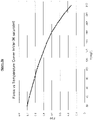
- This particular alloy (known as Invar 36) has a low coefficient of thermal expansion, and importantly a magnetic permeability which, when saturated or near saturation is known to reduce as the temperature increases. An example of this behaviour is illustrated in the Force vs Temperature curve of Figure 2a .
- the Force axis relates to the magnetic attraction force between the first and second magnetic members, while the Temperature axis relates to the temperature of the second magnetic member (Invar 36).
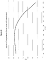
- Figure 2b provides an example of a Force vs Temperature curve for the magnetic attraction force when the invar is not saturated or near saturation. Note that there is a lower variation in attraction force between 20 to 140 degrees Celsius. It is therefore preferable for the present invention to operate with the second magnetic member (110) (Invar 36) at or near saturation.
- Saturation in a magnetic sense is a term well known by those skilled in the art as the state at which an increase in applied magnetic field does not further increase the magnetisation of the material. It is also to be understood that this effect can also be observed under other conditions as known in the art, such as when the material is heated towards its Curie temperature, although the reduction in permeability is more sudden at this point.
- the present invention provides a switch which operates without relying on the Curie temperature. It should also be appreciated that while Invar 36 is desirable for use in the present invention, it is not essential, and other nickel / iron alloys such as Invar 37 (substantially 37% nickel and 63% iron) may be used. Alternatively, the second magnetic member may use any alloy or material which exhibits desirable temperature / permeability characteristics, when saturated or otherwise.
- the second magnetic member (110) may have a magnetic permeability which increases as the temperature increases, or a complex relationship between temperature and magnetic permeability.
- a magnetic permeability which increases as the temperature increases, or a complex relationship between temperature and magnetic permeability.
- an otherwise complex relationship between temperature and magnetic permeability may be suitable for use in a switch of the present invention.
- a cooling device such as a freezer
- the cooling device may be provided by thermal conduction from the freezer, or alternatively the present invention may be provided within the freezer for example as a thermostat. Pairing this cooling device with a second magnetic member which has an increasing magnetic permeability as the temperature increases (across the relevant temperature range) would result in a stronger attraction force between the first and second arms as the freezer warms up, thereby closing the contacts and causing the cooling circuit to start hence regulating temperature.
- the second magnetic member may be a permanent magnet.
- the magnets are positioned such that the north pole of the first magnetic member faces towards the south pole of the second magnetic member (or vice versa). This configuration advantageously provides a greater attraction force when the magnets are spaced apart and can therefore accommodate a greater clearance between the first arm and the second arm.
- a first adjustment device (116) is provided in the form of a cam.
- a second adjustment device (118) is also provided for fine adjustment of the force provided by the biasing means (106). This second adjustment device (118) can be adjusted to compensate for any manufacturing variation in the biasing means (106), first magnetic member (108) or second magnetic member (110).
- the second adjustment device (118) is also configured to transfer the force from the first adjustment device (116) to the biasing means (106).
- Adjustment of the second adjustment device (118) is ideally provided by a threaded connection with the biasing means (106).
- An optional keyed internal aperture for may provide the adjustment means.
- the second adjustment device (118) could consist of other configurations as will be apparent to a person skilled in the art.
- rotation of the first adjustment device (116) modifies the force exerted by the biasing means (106) to separate the first arm (102) from the second arm (104). It does this by varying the radial distance between the centre of the first adjustment device (116) and the surface contacted by the second adjustment device (116).
- the first adjustment device (116) when used as a heater the first adjustment device (116) may be rotated to a region with a low radial distance, therefore reducing the force provided by the biasing means (106), tending the magnetic force to be greater than the biasing force and closing the contacts. This would correspond to a "high" temperature on the heater.
- the first adjustment device (116) comprises an area of high radial distance, which would similarly correspond to a low temperature.
- first adjustment device (116) may, in at least one orientation, cause the biasing means (106) to exert a force in excess of the maximum attraction force capable between the first magnetic member (108) and the second magnetic member (110), thereby safely disabling the switch.
- first adjustment device (116) may, in at least one orientation, cause the biasing means (106) to remove or substantially reduce the biasing force so that the contacts will not open even with minimal/zero attraction force.
- the first adjustment device (116) is a cam as illustrated in the accompanying figures.
- adjustment could be provided by other means such as a slide mechanism, an actuator or an electronic control circuit.
- Such arrangements should be readily implemented by a person skilled in the art.
- a heating device (120) is provided to the second magnetic member (110). It is appreciated however, that the heating device (120) may be provided to the first magnetic member (108), the second magnetic member (110), the shield (802) or any combination of these.
- the heating device (120) is preferably provided to the second arm (104) as the electrical connection to the heating device (120) need not account for the range of movement present in the first arm (102). Methods of providing an electrical connection to a heating device (120) will be well known by those skilled in the art.
- the heating device (120) is preferably a ceramic heater which is connected either in series with the first (112) and second (114) electrical contacts or in parallel with any electrical load.
- the heating device (120) may comprise a resistive heater and / or be printed directly onto the second magnetic member (110).
- a high biasing force, biasing the arms apart can only be overcome by a correspondingly high magnetic attraction force (cool second magnetic member (110), short switch on-time, long switch off-time), and correspondingly a weak biasing force will only be able to overcome a weak magnetic force (hot second magnetic member (110), long switch on-time, short switch off-time).
- Figure 3a shows a simplified view of the switch assembly of the present disclosure wherein the first arm (102) and second arm (104) are in a first position wherein the contacts (112 ,114) are separated and the circuit is open. In this position, the force applied by the biasing means (not illustrated) exceeds the magnetic attraction force between the first magnetic member (108) and second magnetic member (110).
- Figure 3b shows the first arm (102) in a second position wherein the contacts (112, 114) are in contact with one another and the circuit is closed.
- the force applied by the biasing means (not illustrated) is less than the magnetic attraction force between the first magnetic member (108) and second magnetic member (110).
- the first arm may be further displaced to position the first and second magnetic members closer than shown. This may be accommodated by flexibility in the first arm, by using a switching blade as described in co-pending New Zealand Patent Application No. 732824 , or by any other means apparent to those skilled in the art.
- Figure 4 is a cycle diagram which illustrates the hysteresis associated with transitioning between the open and closed states of the switch.
- Two force-temperature curves are provided, the curve marked “CLOSED-heating” shows the force versus temperature curve for when the contacts are closed, and the “OPEN-cooling” curve shows the temperature curve when the contacts are opened.
- the dashed line indicates the force at which the transitioning between the two states occurs.
- the second magnetic member begins heating until the magnetic attraction force between the first magnetic member and second magnetic member drops below the dashed line marked “snap force”. At this point the contacts open and second magnetic member starts cooling (following the "OPEN- cooling” curve). When the magnetic attraction force between the first and second magnetic members exceeds the "snap force" then the switch contacts close, and the diagram transitions back into the "CLOSED- heating" state and the cycle repeats.
- the dots illustrated on the respective curves illustrates the time intervals associated with exponential heating and cooling as would be understood by those skilled in the art.
- the effective PWM duty cycle is a ratio of the time spent with the electrical contacts closed (heating the second magnetic member) and the time spent with the contacts open (second magnetic member cooling to the ambient temperature).
- FIG. 5 provides a lower perspective of the components of the switch of the present disclosure. From this perspective, it can be seen that an adjusting mechanism (500) is provided to the second arm (104). The adjusting mechanism may act upon the first adjustment member or cam (116), or alternatively may be provided to a fixed member attached to the body of the switch (not shown).
- This adjusting mechanism (500) biases the second arm (104) either towards or away from the first arm (102).
- this third adjustment device (500) may be referred to herein as a heater arm bias.
- This adjusting mechanism (500) is ideally threaded into the second arm (104) in a similar fashion as the second adjustment device (118) is provided to the biasing means (106). Adjustment of the adjusting mechanism (500) may also be via an internal keyed aperture (not shown). The effect of adjusting the adjusting mechanism (500) or heater arm bias is illustrated in Figure 6 .
- the Invar needs to be close to saturation. If the Invar is not at or near saturation then the force / temperature curve may be substantially different as shown in Figure 2b .
- the second magnetic member may transition from a near saturated state to a less or non-saturated state, changing the force / temperature characteristics.
- the present disclosure provides a plurality of adjustment means (116, 118) and an adjusting mechanism (500) which allow the separation of the first magnetic member from the second magnetic member and the resulting biasing forces to be adjusted.
- the separation between the first magnetic member (108) and second magnetic member (110) may be reduced by adjusting the adjusting mechanism (500). In doing so the magnetic attraction force will increase. This can be accommodated for by adjusting the second adjustment device (118) in order to increase the biasing force to account for this.
- first adjustment device (116) may act upon the adjusting mechanism (500) to position the second magnetic member (110) closer to the first magnetic member (108), thereby increasing the PWM output duty cycle.
- the electrical clearance between the first and second electrical contacts (112, 114) needs to be kept within the appropriate limits defined by the switching voltage and the applicable safety standards in the country of use.
- the second adjustment device (118) may be adjusted to lower the biasing force to allow the same duty cycle to be achieved with a greater separation between the electrical contacts.
- Figure 6 follows the same principles illustrated in Figure 4 . However, provided are three positions in which the adjusting mechanism (500) or heater arm bias may be set. It will be appreciated that three positions are illustrated for sake of simplicity of the diagram, and the adjusting mechanism (500) may have adjustment positions provided outside of those illustrated, and at any point in between.
- the region of the figure marked with a "2" relates to the adjusting mechanism (500) position 2 which is substantially equivalent to Figure 4 . It would be appreciated that adjusting the adjusting mechanism (500) (either by rotation of the adjusting mechanism or modification of the surface it acts upon) such that the second arm (104) is positioned closer to the first arm (102) would reduce the magnetic attraction force required to close the contacts (112, 114). This is represented by the region marked "1" in Figure 6 .
- region 1 requires a higher temperature before the "snap force" is reached.
- this higher temperature relates to the heating of the second magnetic member (110), it also corresponds to a lower magnetic permeability.
- the lower magnetic attraction forces are required as the first and second magnetic member are now positioned closer together.
- Figure 7 illustrates the effect of adjusting the second adjustment member (118) in order to charge the force applied by the biasing means (106) also referred to herein as the "snap force".
- Three regions are provided with a slight transparency to each. Each region corresponds to the area between the upper and lower curves defined by the point where the dashed Snap Force lines intersect the respective curves.
- Adjustment of the second adjustment member (Snap Force) is shown in three positions only for sake of simplicity, however it is to be appreciated that the second adjustment member (118) may comprise adjustment positions outside of those shown and the disclosure is not limited to discrete adjustment points but rather can be adjusted to any position between the minimum and the maximum.
- adjustment of the first adjustment member (116) is preferably configured to provide adjustment to the force applied by the biasing means (106) in a similar manner as illustrated in Figure 7 .
- Figure 7 will now be discussed with reference to adjustment of the second adjustment member (116) only.
- Adjustment of the second adjustment member (118) to raise the lower portion of the biasing means (106) towards the first arm (102) will increase the force applied by the biasing means (106). This will require a stronger attraction force between the first (108) and second (110) magnetic members in order for the contacts (112, 114) to close.
- the magnetic attraction force is greatest when the magnetic permeability of the second magnetic member (110) is highest (when the second magnetic member (110) is cool). This relates to the region marked "3" in Figure 7 .
- the region marked "1" relates to a lower biasing force due to the second adjustment member (118) lowering the lower portion of the biasing means (106) away from the first arm (102). It can be seen from Figure 7 that the second magnetic member (110) needs to be hotter before the contacts (112, 114) will separate corresponding to a lower magnetic permeability and a lower magnetic attraction force.
- FIG 8 Further improvements can be found in Figure 8 , in which the coupling between the first magnetic member (108) and the second magnetic member (110) is improved.
- This improvement is achieved by providing lateral side members (800) to the second magnetic member (110) or second arm (104), effectively increasing the magnetic field coupling between the first magnetic member (108) and the second magnetic member (110) without needing to limit the travel of the first arm (102).
- method of improving this coupling may be achieved using alternative configurations, including but not limited to providing lateral side members to the first magnetic member (108) and/or the first arm (102).
- the attraction force between the first (102) and second (104) arms may be increased by positioning the first magnetic member (108) and the second magnetic member (110) closer together, for example on the inside edges of the respective arms.
- Ambient temperature compensation is desirable as changes in the ambient temperature may heat or cool the second magnetic member (110) independently of the heating device (120) resulting in a different output or temperature than desired.
- This shield device (802) is preferably constructed from the same material as the second magnetic member (110), and is arranged to at least partially reduce the field strength of the first magnetic member (108) acting upon the second magnetic member (110).
- the reduction in the field strength is a function of the magnetic permeability of the shield device (802), a material with a lower magnetic permeability has less influence on the magnetic field.
- ambient temperature changes within the switch cause temperature variations in the second magnetic member (110) and the shield device (802).
- An increase in temperature of the second magnetic member (110) results in a lower magnetic permeability which in turn reduces the attraction force between the first and second magnetic members (108, 110).
- the shield device (802) also increases, its permeability drops, reducing the shielding effect of the shield (802). This reduction in shielding effect at least partially compensates for the reduction in attraction force between the first and second magnetic members (108, 110), providing a measure of ambient temperature compensation.
- the shield device (802) may be readily modified within the scope of the present disclosure.
- the shield device (802) may be positioned between the first (108) and second magnetic members (110), or alternatively on the opposite side of the first magnetic member (108) to the second magnetic member (110) as shown in Figure 8 .
- the inventor believes that it may be preferable to position the shield device (802) substantially as shown in Figure 8 as it allows for a similar attenuation in the attraction force provided between the first (108) and second magnetic members (110), without needing to include the shield device (802) between the first magnetic member (108) and second magnetic member (110) where space is at a premium.
- the shield device (802) comprises a nickel-iron alloy.
- the nickel-iron alloy comprises around 36% nickel and 64% iron; this particular alloy is known as Invar as discussed above in respect of the second magnetic member (110).
- the shield device (802) prefferably comprises the same alloy as the second magnetic member (110).
- the inventor believes that using the same alloy or at least alloys with similar permeability responses over the desired temperature range results in an at-least partial compensation for ambient temperature.
- the shield device (802) may provide a measure of ambient temperature compensation
- a bi-metallic strip could be provided for the purpose of the ambient temperature compensation.
- the deflection of the bi-metallic strip can provide compensation by acting upon the biasing means (106) or the second arm (104), or the magnetic attraction force provided by the first and second magnetic members (108, 110).
- This configuration still maintains the advantage of at least partially reducing the amount of bi-metallic material required in the switch.
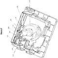
- Figure 9 illustrates a further perspective view of the components of the switch device.
- FIG 10 illustrates a further method of compensating for ambient temperature changes in a switch (1000).
- a third magnetic member (1002) is provided on an opposite opposing side of the first magnetic member (108) to provide an attraction force away from the second magnetic member (110).
- the third magnetic member (1002), and the second magnetic member (110) are constructed at least in part from Invar as described in relation to the previous embodiments.
- the attraction force between the first magnetic member (108) and second magnetic member (110) reduces. This would ordinarily reduce the attraction force between the first arm (102) and second arm (104) which holds the first and second electrical contacts closed (112, 114).
- the third magnetic member (1002) imparts a force to the first magnetic member (108) which opposes the attraction force provided by the second magnetic member (110).
- One further advantage of the configuration shown in Figure 10 is that the presence of the third magnetic member (1002) provides an improved "snap" action as the first arm (102) transitions between the open and closed states (as illustrated in figures 3A and 3B respectively).
- the third magnetic member (1002) is attached to a fixed mounting on the enclosure / housing (1004) of the switch (1000). It will be appreciated that this configuration is in no way limiting on the scope of the invention.
- the third magnetic member (1002) may be adjustably connected to the enclosure / housing (1004) or any other suitable element of the switch. By allowing for adjustment of the location of the third magnetic member (1002) the associated attraction force may be adjusted to account for any manufacturing variations. Examples of suitable adjustment systems are provided herein and other suitable methods of providing positional adjustment will be known to those skilled in the art.
Landscapes
- Physics & Mathematics (AREA)
- Thermal Sciences (AREA)
- Thermally Actuated Switches (AREA)
Claims (15)
- Dispositif de commutation (1000) qui comprend :un premier élément magnétique (108) ;un deuxième élément magnétique (110) qui est magnétiquement attiré par le premier élément magnétique (108) ; caractérisé parun troisième élément magnétique (1002) ;un moyen de sollicitation mécanique (106) conçu pour appliquer une force de sollicitation entre le premier élément magnétique (108) et le deuxième élément magnétique (110) ;un mécanisme de réglage (116)(118) conçu pour permettre le réglage de la force de sollicitation entre le premier élément magnétique (108) et le deuxième élément magnétique (110) ; etun dispositif de chauffage (120) en communication thermique avec l'un des premier et deuxième éléments magnétiques ;lors de l'utilisation, ledit dispositif de chauffage (120) étant conçu pour chauffer le premier ou le deuxième élément magnétique pour réduire la perméabilité magnétique de ceux-ci, réduisant ainsi la force d'attraction magnétique entre lesdits premier et deuxième éléments magnétiques, eten outre ledit troisième élément magnétique (1002) étant structuré et/ou agencé pour compenser au moins partiellement toute variation de la force d'attraction magnétique entre les premier et deuxième éléments magnétiques due aux changements de température ambiante dans le commutateur.
- Dispositif de commutation selon la revendication 1, ledit dispositif de commutation comprenant en outre un premier bras et un second bras.
- Dispositif de commutation selon la revendication 2, ledit premier élément magnétique étant disposé sur le premier bras et ledit deuxième élément magnétique étant disposé sur le second bras.
- Dispositif de commutation selon la revendication 2 ou la revendication 3, ledit premier bras et ledit second bras comprenant chacun un contact électrique.
- Dispositif de commutation selon la revendication 4, ledit contact électrique du premier bras étant conçu pour entrer en contact avec le contact électrique du second bras lors de l'utilisation pour réaliser ainsi un circuit électrique.
- Dispositif de commutation selon la revendication 5, ladite attraction magnétique entre le premier élément magnétique et le deuxième élément magnétique favorisant la connexion du contact électrique du premier bras au contact électrique du second bras.
- Dispositif de commutation selon l'une quelconque des revendications précédentes, ledit premier élément magnétique comprenant un aimant permanent et/ou ledit deuxième élément magnétique et/ou ledit troisième élément magnétique comprenant un matériau ferromagnétique.
- Dispositif de commutation selon la revendication 7, ledit matériau ferromagnétique comprenant un alliage de nickel et de fer.
- Dispositif de commutation selon la revendication 8, ledit matériau ferromagnétique comprenant approximativement 36 % de nickel et approximativement 64 % de fer.
- Dispositif de commutation selon la revendication 5, ledit moyen de sollicitation étant conçu pour s'opposer à une connexion entre le contact électrique du premier bras et le contact électrique du second bras.
- Dispositif de commutation selon l'une quelconque des revendications précédentes, ledit troisième élément magnétique étant conçu pour : a) fournir une force d'attraction qui s'oppose à la force d'attraction entre les premier et deuxième éléments magnétiques ; ou b) atténuer la force d'attraction entre les premier et deuxième éléments magnétiques.
- Dispositif de commutation selon l'une quelconque des revendications précédentes, ledit troisième élément magnétique étant positionné entre le premier élément magnétique et le deuxième élément magnétique.
- Dispositif de commutation selon l'une quelconque des revendications 1 à 11, ledit deuxième élément magnétique étant positionné sur un premier côté du premier élément magnétique, et ledit troisième élément magnétique étant positionné sur un second côté du premier élément magnétique.
- Dispositif de commutation selon l'une quelconque des revendications précédentes, ledit dispositif de chauffage étant un élément chauffant en céramique.
- Dispositif de régulation de température comprenant un dispositif de commutation selon l'une quelconque des revendications précédentes.
Applications Claiming Priority (2)
| Application Number | Priority Date | Filing Date | Title |
|---|---|---|---|
| NZ73412417 | 2017-07-28 | ||
| PCT/NZ2018/050105 WO2019022622A1 (fr) | 2017-07-28 | 2018-07-27 | Commutateur amélioré |
Publications (3)
| Publication Number | Publication Date |
|---|---|
| EP3659166A1 EP3659166A1 (fr) | 2020-06-03 |
| EP3659166A4 EP3659166A4 (fr) | 2021-04-07 |
| EP3659166B1 true EP3659166B1 (fr) | 2022-04-27 |
Family
ID=65040288
Family Applications (1)
| Application Number | Title | Priority Date | Filing Date |
|---|---|---|---|
| EP18837545.5A Not-in-force EP3659166B1 (fr) | 2017-07-28 | 2018-07-27 | Commutateur amélioré |
Country Status (6)
| Country | Link |
|---|---|
| US (1) | US10916395B2 (fr) |
| EP (1) | EP3659166B1 (fr) |
| CN (1) | CN111149185B (fr) |
| AU (1) | AU2018306555B2 (fr) |
| CA (1) | CA3070562C (fr) |
| WO (1) | WO2019022622A1 (fr) |
Family Cites Families (25)
| Publication number | Priority date | Publication date | Assignee | Title |
|---|---|---|---|---|
| GB578611A (en) * | 1942-12-21 | 1946-07-04 | Landis & Gyr Sa | An improved thermally operated electric switching device |
| US2575086A (en) * | 1947-02-14 | 1951-11-13 | Gen Electric | Magnetic valve |
| US2718569A (en) * | 1951-08-22 | 1955-09-20 | Gunnard Z Johnston | Circuit breakers |
| GB755457A (en) * | 1954-04-27 | 1956-08-22 | Rheostatic Co Ltd | Improvements in and relating to safety control devices for burners when firing furnaces |
| US3009047A (en) * | 1959-10-09 | 1961-11-14 | Gen Electric | Temperature responsive control device |
| US3110789A (en) | 1959-11-19 | 1963-11-12 | Robertshaw Controls Co | Thermally actuated cycling switch |
| US2960588A (en) | 1959-11-30 | 1960-11-15 | Thermolyne Corp | Control device |
| US3206573A (en) * | 1961-11-14 | 1965-09-14 | American Radiator & Standard | Thermo-magnetic control comprising a thermo-influenced magnetic element and a permanent magnet |
| NL6709917A (fr) * | 1967-07-17 | 1969-01-21 | ||
| DK131528B (da) * | 1967-10-07 | 1975-07-28 | Danfoss As | Startkontakt for en enfaset motor. |
| CA921523A (en) * | 1971-08-06 | 1973-02-20 | Honeywell Controls Limited | Thermoferrite switch with ptc resistor temperature compensation |
| SE364791B (fr) * | 1972-07-10 | 1974-03-04 | A Larsson | |
| US3905003A (en) * | 1974-01-28 | 1975-09-09 | Robertshaw Controls Co | Electrical switch construction and parts therefor |
| DE3444223A1 (de) | 1984-12-04 | 1986-06-05 | Ranco Inc., Dublin, Ohio | Schaltrelais |
| US5168545A (en) * | 1991-02-13 | 1992-12-01 | Robertshaw Controls Company | Temperature operated control system, control device therefor, and methods of making the same |
| EP0645051B1 (fr) | 1992-06-08 | 1998-09-09 | Strix Limited | Regulateur d'energie |
| CN2141931Y (zh) * | 1992-10-29 | 1993-09-08 | 江门市泰来电子仪器厂 | 磁热定时开关 |
| CN2149014Y (zh) * | 1993-01-01 | 1993-12-08 | 章柏元 | 手动复位式电器、电路保险装置 |
| CN100394525C (zh) * | 2006-03-13 | 2008-06-11 | 颜陶 | 电饭煲全自动限温中心开关 |
| CN101295183A (zh) * | 2007-04-24 | 2008-10-29 | 深圳市贝斯达医疗器械有限公司 | 一种永磁共振磁体温度恒定控制系统 |
| CN101114551A (zh) * | 2007-08-30 | 2008-01-30 | 上海交通大学 | 常闭微型磁性热敏开关 |
| CN102610439B (zh) * | 2011-12-16 | 2015-02-25 | 佛山市川东磁电股份有限公司 | 一种电热容器磁敏温控装置 |
| CN202307686U (zh) * | 2011-11-04 | 2012-07-04 | 佛山市高明欧一电子制造有限公司 | 手动复位磁性限温器 |
| CN204885017U (zh) * | 2015-06-25 | 2015-12-16 | 广东德豪雷士照明有限公司 | 跷板式开关、过温保护电路及led灯具 |
| EP3642860A4 (fr) | 2017-06-21 | 2021-03-31 | Introl IP Limited | Interrupteur électrique et lame de commutation associée |
-
2018
- 2018-07-27 US US16/634,392 patent/US10916395B2/en not_active Expired - Fee Related
- 2018-07-27 WO PCT/NZ2018/050105 patent/WO2019022622A1/fr not_active Ceased
- 2018-07-27 AU AU2018306555A patent/AU2018306555B2/en not_active Ceased
- 2018-07-27 CN CN201880063364.0A patent/CN111149185B/zh not_active Expired - Fee Related
- 2018-07-27 EP EP18837545.5A patent/EP3659166B1/fr not_active Not-in-force
- 2018-07-27 CA CA3070562A patent/CA3070562C/fr active Active
Also Published As
| Publication number | Publication date |
|---|---|
| WO2019022622A1 (fr) | 2019-01-31 |
| AU2018306555B2 (en) | 2021-12-23 |
| CN111149185A (zh) | 2020-05-12 |
| CA3070562C (fr) | 2023-06-13 |
| EP3659166A4 (fr) | 2021-04-07 |
| US10916395B2 (en) | 2021-02-09 |
| EP3659166A1 (fr) | 2020-06-03 |
| CN111149185B (zh) | 2022-03-25 |
| CA3070562A1 (fr) | 2019-01-31 |
| AU2018306555A1 (en) | 2020-03-12 |
| US20200381201A1 (en) | 2020-12-03 |
Similar Documents
| Publication | Publication Date | Title |
|---|---|---|
| CA2789382C (fr) | Dispositif de commutation electromagnetique a gestion thermique | |
| US4206344A (en) | Electric power controllers | |
| US20040150504A1 (en) | Resettable ferromagnetic thermal switch | |
| DK2747110T3 (en) | Temperature Protection Circuit | |
| JP2012023040A (ja) | コンタクト保護回路およびこれを含む高電圧リレー | |
| GB1563026A (en) | Controllers for controlling the supply of electrical power to a load | |
| KR20000071862A (ko) | 개선된 전기 콘택트를 가진 전자 장치 및 이것에 사용되는전기 콘택트 | |
| US20200251292A1 (en) | Relay | |
| EP3659166B1 (fr) | Commutateur amélioré | |
| CN107044561B (zh) | 可控温的燃气阀体装置 | |
| US2707215A (en) | Safety cut-outs for electrically heated appliances | |
| USRE31597E (en) | Electric power controllers | |
| US3688060A (en) | Electrical switch means for effecting sequential operation | |
| EP3981019B1 (fr) | Système de contact électrique pour dispositif de commutation | |
| US4527142A (en) | Delayed-action thermal relay | |
| US2960588A (en) | Control device | |
| CN116741598A (zh) | 电路保护装置、方法、断路器和电气设备 | |
| JP7487623B2 (ja) | 過電流スイッチ及びこの過電流スイッチを備えた回路遮断器 | |
| JP2020077472A (ja) | マイクロ継電器 | |
| US2835762A (en) | Anti-chatter switch | |
| SU1488889A1 (ru) | Abtomatичeckий bыkлючateль | |
| JP2025168742A (ja) | 直流高電圧電流のプロテクター | |
| KR200236254Y1 (ko) | 과전류 차단기를 구비한 스위치 | |
| JPH07161276A (ja) | 回路遮断器 | |
| JPH07122174A (ja) | 回路遮断器 |
Legal Events
| Date | Code | Title | Description |
|---|---|---|---|
| STAA | Information on the status of an ep patent application or granted ep patent |
Free format text: STATUS: THE INTERNATIONAL PUBLICATION HAS BEEN MADE |
|
| PUAI | Public reference made under article 153(3) epc to a published international application that has entered the european phase |
Free format text: ORIGINAL CODE: 0009012 |
|
| STAA | Information on the status of an ep patent application or granted ep patent |
Free format text: STATUS: REQUEST FOR EXAMINATION WAS MADE |
|
| 17P | Request for examination filed |
Effective date: 20200220 |
|
| AK | Designated contracting states |
Kind code of ref document: A1 Designated state(s): AL AT BE BG CH CY CZ DE DK EE ES FI FR GB GR HR HU IE IS IT LI LT LU LV MC MK MT NL NO PL PT RO RS SE SI SK SM TR |
|
| AX | Request for extension of the european patent |
Extension state: BA ME |
|
| DAV | Request for validation of the european patent (deleted) | ||
| DAX | Request for extension of the european patent (deleted) | ||
| A4 | Supplementary search report drawn up and despatched |
Effective date: 20210310 |
|
| RIC1 | Information provided on ipc code assigned before grant |
Ipc: H01H 37/58 20060101AFI20210303BHEP Ipc: H01H 37/66 20060101ALI20210303BHEP |
|
| GRAP | Despatch of communication of intention to grant a patent |
Free format text: ORIGINAL CODE: EPIDOSNIGR1 |
|
| STAA | Information on the status of an ep patent application or granted ep patent |
Free format text: STATUS: GRANT OF PATENT IS INTENDED |
|
| INTG | Intention to grant announced |
Effective date: 20220208 |
|
| GRAS | Grant fee paid |
Free format text: ORIGINAL CODE: EPIDOSNIGR3 |
|
| GRAA | (expected) grant |
Free format text: ORIGINAL CODE: 0009210 |
|
| STAA | Information on the status of an ep patent application or granted ep patent |
Free format text: STATUS: THE PATENT HAS BEEN GRANTED |
|
| RAP3 | Party data changed (applicant data changed or rights of an application transferred) |
Owner name: MAGGMA GROUP IP LIMITED |
|
| AK | Designated contracting states |
Kind code of ref document: B1 Designated state(s): AL AT BE BG CH CY CZ DE DK EE ES FI FR GB GR HR HU IE IS IT LI LT LU LV MC MK MT NL NO PL PT RO RS SE SI SK SM TR |
|
| REG | Reference to a national code |
Ref country code: GB Ref legal event code: FG4D |
|
| REG | Reference to a national code |
Ref country code: CH Ref legal event code: EP |
|
| REG | Reference to a national code |
Ref country code: AT Ref legal event code: REF Ref document number: 1487602 Country of ref document: AT Kind code of ref document: T Effective date: 20220515 |
|
| REG | Reference to a national code |
Ref country code: DE Ref legal event code: R096 Ref document number: 602018034651 Country of ref document: DE |
|
| REG | Reference to a national code |
Ref country code: IE Ref legal event code: FG4D |
|
| REG | Reference to a national code |
Ref country code: LT Ref legal event code: MG9D |
|
| REG | Reference to a national code |
Ref country code: NL Ref legal event code: MP Effective date: 20220427 |
|
| REG | Reference to a national code |
Ref country code: AT Ref legal event code: MK05 Ref document number: 1487602 Country of ref document: AT Kind code of ref document: T Effective date: 20220427 |
|
| PG25 | Lapsed in a contracting state [announced via postgrant information from national office to epo] |
Ref country code: NL Free format text: LAPSE BECAUSE OF FAILURE TO SUBMIT A TRANSLATION OF THE DESCRIPTION OR TO PAY THE FEE WITHIN THE PRESCRIBED TIME-LIMIT Effective date: 20220427 |
|
| PG25 | Lapsed in a contracting state [announced via postgrant information from national office to epo] |
Ref country code: SE Free format text: LAPSE BECAUSE OF FAILURE TO SUBMIT A TRANSLATION OF THE DESCRIPTION OR TO PAY THE FEE WITHIN THE PRESCRIBED TIME-LIMIT Effective date: 20220427 Ref country code: PT Free format text: LAPSE BECAUSE OF FAILURE TO SUBMIT A TRANSLATION OF THE DESCRIPTION OR TO PAY THE FEE WITHIN THE PRESCRIBED TIME-LIMIT Effective date: 20220829 Ref country code: NO Free format text: LAPSE BECAUSE OF FAILURE TO SUBMIT A TRANSLATION OF THE DESCRIPTION OR TO PAY THE FEE WITHIN THE PRESCRIBED TIME-LIMIT Effective date: 20220727 Ref country code: LT Free format text: LAPSE BECAUSE OF FAILURE TO SUBMIT A TRANSLATION OF THE DESCRIPTION OR TO PAY THE FEE WITHIN THE PRESCRIBED TIME-LIMIT Effective date: 20220427 Ref country code: HR Free format text: LAPSE BECAUSE OF FAILURE TO SUBMIT A TRANSLATION OF THE DESCRIPTION OR TO PAY THE FEE WITHIN THE PRESCRIBED TIME-LIMIT Effective date: 20220427 Ref country code: GR Free format text: LAPSE BECAUSE OF FAILURE TO SUBMIT A TRANSLATION OF THE DESCRIPTION OR TO PAY THE FEE WITHIN THE PRESCRIBED TIME-LIMIT Effective date: 20220728 Ref country code: FI Free format text: LAPSE BECAUSE OF FAILURE TO SUBMIT A TRANSLATION OF THE DESCRIPTION OR TO PAY THE FEE WITHIN THE PRESCRIBED TIME-LIMIT Effective date: 20220427 Ref country code: ES Free format text: LAPSE BECAUSE OF FAILURE TO SUBMIT A TRANSLATION OF THE DESCRIPTION OR TO PAY THE FEE WITHIN THE PRESCRIBED TIME-LIMIT Effective date: 20220427 Ref country code: BG Free format text: LAPSE BECAUSE OF FAILURE TO SUBMIT A TRANSLATION OF THE DESCRIPTION OR TO PAY THE FEE WITHIN THE PRESCRIBED TIME-LIMIT Effective date: 20220727 Ref country code: AT Free format text: LAPSE BECAUSE OF FAILURE TO SUBMIT A TRANSLATION OF THE DESCRIPTION OR TO PAY THE FEE WITHIN THE PRESCRIBED TIME-LIMIT Effective date: 20220427 |
|
| PG25 | Lapsed in a contracting state [announced via postgrant information from national office to epo] |
Ref country code: RS Free format text: LAPSE BECAUSE OF FAILURE TO SUBMIT A TRANSLATION OF THE DESCRIPTION OR TO PAY THE FEE WITHIN THE PRESCRIBED TIME-LIMIT Effective date: 20220427 Ref country code: PL Free format text: LAPSE BECAUSE OF FAILURE TO SUBMIT A TRANSLATION OF THE DESCRIPTION OR TO PAY THE FEE WITHIN THE PRESCRIBED TIME-LIMIT Effective date: 20220427 Ref country code: LV Free format text: LAPSE BECAUSE OF FAILURE TO SUBMIT A TRANSLATION OF THE DESCRIPTION OR TO PAY THE FEE WITHIN THE PRESCRIBED TIME-LIMIT Effective date: 20220427 Ref country code: IS Free format text: LAPSE BECAUSE OF FAILURE TO SUBMIT A TRANSLATION OF THE DESCRIPTION OR TO PAY THE FEE WITHIN THE PRESCRIBED TIME-LIMIT Effective date: 20220827 |
|
| REG | Reference to a national code |
Ref country code: DE Ref legal event code: R097 Ref document number: 602018034651 Country of ref document: DE |
|
| PG25 | Lapsed in a contracting state [announced via postgrant information from national office to epo] |
Ref country code: SM Free format text: LAPSE BECAUSE OF FAILURE TO SUBMIT A TRANSLATION OF THE DESCRIPTION OR TO PAY THE FEE WITHIN THE PRESCRIBED TIME-LIMIT Effective date: 20220427 Ref country code: SK Free format text: LAPSE BECAUSE OF FAILURE TO SUBMIT A TRANSLATION OF THE DESCRIPTION OR TO PAY THE FEE WITHIN THE PRESCRIBED TIME-LIMIT Effective date: 20220427 Ref country code: RO Free format text: LAPSE BECAUSE OF FAILURE TO SUBMIT A TRANSLATION OF THE DESCRIPTION OR TO PAY THE FEE WITHIN THE PRESCRIBED TIME-LIMIT Effective date: 20220427 Ref country code: EE Free format text: LAPSE BECAUSE OF FAILURE TO SUBMIT A TRANSLATION OF THE DESCRIPTION OR TO PAY THE FEE WITHIN THE PRESCRIBED TIME-LIMIT Effective date: 20220427 Ref country code: DK Free format text: LAPSE BECAUSE OF FAILURE TO SUBMIT A TRANSLATION OF THE DESCRIPTION OR TO PAY THE FEE WITHIN THE PRESCRIBED TIME-LIMIT Effective date: 20220427 Ref country code: CZ Free format text: LAPSE BECAUSE OF FAILURE TO SUBMIT A TRANSLATION OF THE DESCRIPTION OR TO PAY THE FEE WITHIN THE PRESCRIBED TIME-LIMIT Effective date: 20220427 |
|
| PG25 | Lapsed in a contracting state [announced via postgrant information from national office to epo] |
Ref country code: MC Free format text: LAPSE BECAUSE OF FAILURE TO SUBMIT A TRANSLATION OF THE DESCRIPTION OR TO PAY THE FEE WITHIN THE PRESCRIBED TIME-LIMIT Effective date: 20220427 |
|
| REG | Reference to a national code |
Ref country code: CH Ref legal event code: PL |
|
| PLBE | No opposition filed within time limit |
Free format text: ORIGINAL CODE: 0009261 |
|
| STAA | Information on the status of an ep patent application or granted ep patent |
Free format text: STATUS: NO OPPOSITION FILED WITHIN TIME LIMIT |
|
| REG | Reference to a national code |
Ref country code: BE Ref legal event code: MM Effective date: 20220731 |
|
| PG25 | Lapsed in a contracting state [announced via postgrant information from national office to epo] |
Ref country code: AL Free format text: LAPSE BECAUSE OF FAILURE TO SUBMIT A TRANSLATION OF THE DESCRIPTION OR TO PAY THE FEE WITHIN THE PRESCRIBED TIME-LIMIT Effective date: 20220427 |
|
| 26N | No opposition filed |
Effective date: 20230130 |
|
| PG25 | Lapsed in a contracting state [announced via postgrant information from national office to epo] |
Ref country code: LU Free format text: LAPSE BECAUSE OF NON-PAYMENT OF DUE FEES Effective date: 20220727 Ref country code: LI Free format text: LAPSE BECAUSE OF NON-PAYMENT OF DUE FEES Effective date: 20220731 Ref country code: CH Free format text: LAPSE BECAUSE OF NON-PAYMENT OF DUE FEES Effective date: 20220731 |
|
| PG25 | Lapsed in a contracting state [announced via postgrant information from national office to epo] |
Ref country code: SI Free format text: LAPSE BECAUSE OF FAILURE TO SUBMIT A TRANSLATION OF THE DESCRIPTION OR TO PAY THE FEE WITHIN THE PRESCRIBED TIME-LIMIT Effective date: 20220427 Ref country code: BE Free format text: LAPSE BECAUSE OF NON-PAYMENT OF DUE FEES Effective date: 20220731 |
|
| PG25 | Lapsed in a contracting state [announced via postgrant information from national office to epo] |
Ref country code: IE Free format text: LAPSE BECAUSE OF NON-PAYMENT OF DUE FEES Effective date: 20220727 |
|
| PGFP | Annual fee paid to national office [announced via postgrant information from national office to epo] |
Ref country code: GB Payment date: 20230725 Year of fee payment: 6 |
|
| PGFP | Annual fee paid to national office [announced via postgrant information from national office to epo] |
Ref country code: FR Payment date: 20230725 Year of fee payment: 6 Ref country code: DE Payment date: 20230726 Year of fee payment: 6 |
|
| PG25 | Lapsed in a contracting state [announced via postgrant information from national office to epo] |
Ref country code: IT Free format text: LAPSE BECAUSE OF FAILURE TO SUBMIT A TRANSLATION OF THE DESCRIPTION OR TO PAY THE FEE WITHIN THE PRESCRIBED TIME-LIMIT Effective date: 20220427 |
|
| PG25 | Lapsed in a contracting state [announced via postgrant information from national office to epo] |
Ref country code: MK Free format text: LAPSE BECAUSE OF FAILURE TO SUBMIT A TRANSLATION OF THE DESCRIPTION OR TO PAY THE FEE WITHIN THE PRESCRIBED TIME-LIMIT Effective date: 20220427 Ref country code: CY Free format text: LAPSE BECAUSE OF FAILURE TO SUBMIT A TRANSLATION OF THE DESCRIPTION OR TO PAY THE FEE WITHIN THE PRESCRIBED TIME-LIMIT Effective date: 20220427 |
|
| PG25 | Lapsed in a contracting state [announced via postgrant information from national office to epo] |
Ref country code: HU Free format text: LAPSE BECAUSE OF FAILURE TO SUBMIT A TRANSLATION OF THE DESCRIPTION OR TO PAY THE FEE WITHIN THE PRESCRIBED TIME-LIMIT; INVALID AB INITIO Effective date: 20180727 |
|
| PG25 | Lapsed in a contracting state [announced via postgrant information from national office to epo] |
Ref country code: TR Free format text: LAPSE BECAUSE OF FAILURE TO SUBMIT A TRANSLATION OF THE DESCRIPTION OR TO PAY THE FEE WITHIN THE PRESCRIBED TIME-LIMIT Effective date: 20220427 |
|
| PG25 | Lapsed in a contracting state [announced via postgrant information from national office to epo] |
Ref country code: MT Free format text: LAPSE BECAUSE OF FAILURE TO SUBMIT A TRANSLATION OF THE DESCRIPTION OR TO PAY THE FEE WITHIN THE PRESCRIBED TIME-LIMIT Effective date: 20220427 |
|
| PG25 | Lapsed in a contracting state [announced via postgrant information from national office to epo] |
Ref country code: BG Free format text: LAPSE BECAUSE OF FAILURE TO SUBMIT A TRANSLATION OF THE DESCRIPTION OR TO PAY THE FEE WITHIN THE PRESCRIBED TIME-LIMIT Effective date: 20220427 |
|
| PG25 | Lapsed in a contracting state [announced via postgrant information from national office to epo] |
Ref country code: BG Free format text: LAPSE BECAUSE OF FAILURE TO SUBMIT A TRANSLATION OF THE DESCRIPTION OR TO PAY THE FEE WITHIN THE PRESCRIBED TIME-LIMIT Effective date: 20220427 |
|
| REG | Reference to a national code |
Ref country code: DE Ref legal event code: R119 Ref document number: 602018034651 Country of ref document: DE |
|
| GBPC | Gb: european patent ceased through non-payment of renewal fee |
Effective date: 20240727 |
|
| PG25 | Lapsed in a contracting state [announced via postgrant information from national office to epo] |
Ref country code: DE Free format text: LAPSE BECAUSE OF NON-PAYMENT OF DUE FEES Effective date: 20250201 |
|
| PG25 | Lapsed in a contracting state [announced via postgrant information from national office to epo] |
Ref country code: FR Free format text: LAPSE BECAUSE OF NON-PAYMENT OF DUE FEES Effective date: 20240731 |
|
| PG25 | Lapsed in a contracting state [announced via postgrant information from national office to epo] |
Ref country code: GB Free format text: LAPSE BECAUSE OF NON-PAYMENT OF DUE FEES Effective date: 20240727 |