EP3659189B1 - Bewegungsverstärkende betätigungsvorrichtung - Google Patents
Bewegungsverstärkende betätigungsvorrichtung Download PDFInfo
- Publication number
- EP3659189B1 EP3659189B1 EP18753092.8A EP18753092A EP3659189B1 EP 3659189 B1 EP3659189 B1 EP 3659189B1 EP 18753092 A EP18753092 A EP 18753092A EP 3659189 B1 EP3659189 B1 EP 3659189B1
- Authority
- EP
- European Patent Office
- Prior art keywords
- axis
- flexible
- platform
- actuation
- arm
- Prior art date
- Legal status (The legal status is an assumption and is not a legal conclusion. Google has not performed a legal analysis and makes no representation as to the accuracy of the status listed.)
- Active
Links
Images




Classifications
-
- H—ELECTRICITY
- H02—GENERATION; CONVERSION OR DISTRIBUTION OF ELECTRIC POWER
- H02N—ELECTRIC MACHINES NOT OTHERWISE PROVIDED FOR
- H02N2/00—Electric machines in general using piezoelectric effect, electrostriction or magnetostriction
-
- A—HUMAN NECESSITIES
- A61—MEDICAL OR VETERINARY SCIENCE; HYGIENE
- A61B—DIAGNOSIS; SURGERY; IDENTIFICATION
- A61B34/00—Computer-aided surgery; Manipulators or robots specially adapted for use in surgery
- A61B34/70—Manipulators specially adapted for use in surgery
- A61B34/72—Micromanipulators
-
- B—PERFORMING OPERATIONS; TRANSPORTING
- B25—HAND TOOLS; PORTABLE POWER-DRIVEN TOOLS; MANIPULATORS
- B25J—MANIPULATORS; CHAMBERS PROVIDED WITH MANIPULATION DEVICES
- B25J18/00—Arms
- B25J18/005—Arms having a curved shape
-
- B—PERFORMING OPERATIONS; TRANSPORTING
- B25—HAND TOOLS; PORTABLE POWER-DRIVEN TOOLS; MANIPULATORS
- B25J—MANIPULATORS; CHAMBERS PROVIDED WITH MANIPULATION DEVICES
- B25J7/00—Micromanipulators
-
- B—PERFORMING OPERATIONS; TRANSPORTING
- B25—HAND TOOLS; PORTABLE POWER-DRIVEN TOOLS; MANIPULATORS
- B25J—MANIPULATORS; CHAMBERS PROVIDED WITH MANIPULATION DEVICES
- B25J9/00—Program-controlled manipulators
- B25J9/0009—Constructional details, e.g. manipulator supports, bases
- B25J9/0015—Flexure members, i.e. parts of manipulators having a narrowed section allowing articulation by flexion
-
- B—PERFORMING OPERATIONS; TRANSPORTING
- B25—HAND TOOLS; PORTABLE POWER-DRIVEN TOOLS; MANIPULATORS
- B25J—MANIPULATORS; CHAMBERS PROVIDED WITH MANIPULATION DEVICES
- B25J9/00—Program-controlled manipulators
- B25J9/003—Program-controlled manipulators having parallel kinematics
-
- B—PERFORMING OPERATIONS; TRANSPORTING
- B25—HAND TOOLS; PORTABLE POWER-DRIVEN TOOLS; MANIPULATORS
- B25J—MANIPULATORS; CHAMBERS PROVIDED WITH MANIPULATION DEVICES
- B25J9/00—Program-controlled manipulators
- B25J9/10—Program-controlled manipulators characterised by positioning means for manipulator elements
- B25J9/12—Program-controlled manipulators characterised by positioning means for manipulator elements electric
-
- H—ELECTRICITY
- H02—GENERATION; CONVERSION OR DISTRIBUTION OF ELECTRIC POWER
- H02N—ELECTRIC MACHINES NOT OTHERWISE PROVIDED FOR
- H02N2/00—Electric machines in general using piezoelectric effect, electrostriction or magnetostriction
- H02N2/02—Electric machines in general using piezoelectric effect, electrostriction or magnetostriction producing linear motion, e.g. actuators; Linear positioners ; Linear motors
- H02N2/04—Constructional details
- H02N2/043—Mechanical transmission means, e.g. for stroke amplification
- H02N2/046—Mechanical transmission means, e.g. for stroke amplification for conversion into rotary motion
-
- H—ELECTRICITY
- H02—GENERATION; CONVERSION OR DISTRIBUTION OF ELECTRIC POWER
- H02N—ELECTRIC MACHINES NOT OTHERWISE PROVIDED FOR
- H02N2/00—Electric machines in general using piezoelectric effect, electrostriction or magnetostriction
- H02N2/10—Electric machines in general using piezoelectric effect, electrostriction or magnetostriction producing rotary motion, e.g. rotary motors
- H02N2/108—Electric machines in general using piezoelectric effect, electrostriction or magnetostriction producing rotary motion, e.g. rotary motors around multiple axes of rotation, e.g. spherical rotor motors
-
- H—ELECTRICITY
- H10—SEMICONDUCTOR DEVICES; ELECTRIC SOLID-STATE DEVICES NOT OTHERWISE PROVIDED FOR
- H10N—ELECTRIC SOLID-STATE DEVICES NOT OTHERWISE PROVIDED FOR
- H10N30/00—Piezoelectric or electrostrictive devices
- H10N30/20—Piezoelectric or electrostrictive devices with electrical input and mechanical output, e.g. functioning as actuators or vibrators
- H10N30/204—Piezoelectric or electrostrictive devices with electrical input and mechanical output, e.g. functioning as actuators or vibrators using bending displacement, e.g. unimorph, bimorph or multimorph cantilever or membrane benders
- H10N30/2041—Beam type
- H10N30/2042—Cantilevers, i.e. having one fixed end
- H10N30/2044—Cantilevers, i.e. having one fixed end having multiple segments mechanically connected in series, e.g. zig-zag type
Definitions
- the invention relates to amplified actuation devices, more precisely miniaturized devices, occupying a volume of the order of ten cubic millimeters.
- the invention can find many applications, in particular for operating a platform.
- This platform can accommodate a mirror to reflect a laser beam.
- the laser beam to be thus used for marking and / or laser engraving, for 3D scanning, in the field of (micro) robotics (laser vision for example), in the field of telecommunications (for example for an attenuator variable optics or an optical switch), or for medical applications (minimally invasive endoscopic surgery, optical exploration with or without biopsy, etc.).
- the invention has been specifically developed for laser microsurgery of the vocal cords, or phonosurgery, with the objective of guiding a laser beam precisely towards the vocal cords.
- phonosurgery is defined as follows: “all surgical procedures which maintain, restore or improve the human voice", or “the science of manipulating the vibratory elements of the larynx in order to restore vocal function”. This involves the excision of the tissue mass which could be a benign mass or a cancerous lesion.
- the use of the scalpel is replaced by the use of laser technologies.
- the traditional methodology prevalent for remote control of the surgical laser is a mechanical manipulator, with a surgical microscope positioned to view the vocal cords to be treated, as illustrated in figure 1 .
- This mechanical manipulator and the laser source are located approximately 400 mm from the vocal cords.
- several of the difficulties associated with the use of this conventional mechanical manipulator are related to the ergonomics of the device.
- the clinician has no practical means to stabilize his hand while performing the precise and delicate movements necessary to precisely and consistently orient the surgical laser.
- teleoperated surgical systems based on a microrobot have been developed as a terminal system of an adjustable flexible endoscope (or flexible laryngoscope in the case of vocal cords) to insert the microrobot and cameras inside the body of the patient. patient, eliminating the need for the surgical microscope, and allowing access to areas not accessible by the previous technique.
- adjustable flexible endoscope or flexible laryngoscope in the case of vocal cords
- These new laser microsurgery systems offer better accessibility and better precision than previous systems.
- endoscopic systems implementing the diffraction of a laser, using prisms or lenses.
- the existing systems do not have a sufficient angle to reach all of the vocal cords: the direction of the laser beam which is managed by refraction (using prisms and lenses) has modest angular ranges (around 2 degrees).
- the inventors therefore preferred to opt for a system based on the reflection of a laser using a mirror.
- the laser beam is reflected by a plane mirror located on the platform of a microrobot.
- the laser beam will be delivered by an optical fiber from the outside to the distal end of the laryngoscope.
- a mirror is placed in order to focus the laser beam and, at the same time, to reflect it on the platform of the microrobot.
- a plane mirror reflects this laser beam on the vocal cords.
- the orientation of the plane mirror is guided by the microrobot and is carried out by a remote control.
- the microrobot directs the laser on the vocal cords.
- This complex robot must fulfill at least the two functions which are: the function of orientation of the mirror along two axes of rotation and in the desired angular range, and the remote actuation function of said rotations to reach the desired angular range, with precision (resolution) and minimum movement speed (bandwidth) meeting the above-mentioned criteria.
- the invention relates to the second function, that is to say to the remote actuation function of said rotations.
- the objective is to have an actuation device which makes it possible to actuate an object according to a given minimum amplitude, in precision and in speed, this actuation device having to be included in a cube less than 10 x 10 x 10 mm 3 .
- Actuators transform a type of electrical, thermal, magnetic or other energy into movements or mechanical loads.
- Actuators are key components of robotics.
- micro-actuator the word used to designate an actuator is "micro-actuator”.
- Microactuators are often made of active or intelligent materials that typically need to provide micrometric or submicron resolution. Active materials have desirable characteristics such as high resolution and / or high bandwidth. In addition, most of them can also be used as detectors or sensors.
- micro-actuator The dimensions of a micro-actuator are generally less than 10 mm.
- microactuators best suited to the above-mentioned criteria are piezoelectric microactuators.
- piezoelectric microactuators We use the phenomenon of piezoelectricity which causes electrical charges to appear on the surfaces of a material when it is exposed to a mechanical load - this is called the direct piezoelectric effect - and conversely a deformation is obtained when 'an electric field is applied. It is this reverse effect which is exploited for an actuator.
- Piezoelectric microactuators offer high resolution (down to a few nanometers), high bandwidth (up to tens or hundreds of kilohertz), and high force density compared to other smart materials, making them makes it suitable for the design of microactuators.
- these are structures 90 of rectangular section, preferably configured as a cantilever.
- These structures comprise an active layer 91, comprising a piezoelectric material, the active layer 91 being taken between two electrodes 94, 95 capable of exciting the active piezoelectric material.
- an active layer 91 comprising a piezoelectric material
- the active layer 91 being taken between two electrodes 94, 95 capable of exciting the active piezoelectric material.
- a unimorphic structure can comprise an additional layer, called a passive layer, which can be a layer of a soft or flexible material, and which can be fixed against one of the electrodes.
- a passive layer makes it possible to generate the exploitable curvature of the beam when the active layer is fed.
- This passive layer can be conductive and function as an electrode.
- These structures can include several active layers, for example.
- We speak of a bimorphic structure if there are at least two active layers 91, 92 ( figure 2a ). Each active layer 91, 92 is taken between two electrodes 94, 95, 96 capable of exciting the active piezoelectric material. Bimorphic beams allow greater displacements.
- We speak more generally of a multimorphic structure if there are two or more active layers.
- a multimorphic structure can also include an additional layer, called a passive layer.
- the passive layer in a multimorphic structure helps to increase the rigidity of the structure.
- Means 150 must be provided to supply the electrodes electrically and to excite the piezoelectric materials.
- Such a structure 90 can be called a piezoelectric beam, or a beam comprising a piezoelectric element.
- one of the ends 90a of the beam 90 is fixed, and the other 90a describes a bending movement on either side of a reference position called the rest position.
- a piezoelectric beam can thus bend around said rest position, up to a maximum angle ⁇ max corresponding to a bending amplitude of approximately 150 to 200 ⁇ m for a beam of 10mm x 2mm x 0.3mm of a piezoelectric material PZT-5A, and in bimorph structure.
- millimeter-order amplitudes are sought, while minimizing the dimensions of the beam and the applied tension, while maintaining good dynamics of movement of the beam.
- the patent document FR2850218 describes an amplified displacement piezoelectric actuator comprising a mechanical displacement amplifier connected to a load and to a base, and having an elliptical shell shape made of a deformable elastic material, and piezoelectric elements mounted inside said shell in the direction of the major axis of the shell, and electrically excited to produce a longitudinal deformation of said major axis and induce a deformation of the minor axis intended to generate at the interface with the load a displacement whose component along the minor axis is amplified.
- document FR2362525 describes a piezoelectric stepper motor, consisting of a fixed guide member, a piezoelectric column movable thereon and serving as a drive member, and a piezoelectric device clamp arranged on the column.
- the aforementioned patent document implements piezoelectric actuators of the stack type, that is to say using another form of piezoelectric actuation.
- Stack piezoelectric actuators do not use the bimetal effect, but a displacement directly obtained by the deformation of the piezoelectric material.
- the dimensions of the stacks are relatively large, and the displacements generated are very small, however they have a much greater force than bimetallic beams.
- Their purpose is to improve the damping capacities of a piezoelectric actuator and its resistance to dynamic external forces.
- the amplified displacement piezoelectric actuator according to this patent document is a system constrained in terms of amplitude and displacement speed by virtue of its shell structure.
- an actuation device in particular a micro-actuator having both a high displacement speed (for example a speed corresponding to a response time of 1 ms) and an amplitude of significant bending (for example of the order of one mm), that is to say much more than the known microactuators allow.
- a high displacement speed for example a speed corresponding to a response time of 1 ms
- an amplitude of significant bending for example of the order of one mm
- the amplitudes delivered must also be precise and must be able to be controlled with a precision, for example of the order of 50 ⁇ m per 1 mm.
- articulation should be understood to mean a means of assembling two beams which allows articulation according to one or two degrees of freedom. This articulation allows the movements of the beams to be amplified.
- the device is configured such that the cumulative effects of the bending received by the segment between the pivot point and the first end of the second beam and the bending of said second beam when a tension is applied to it generates movement flexion amplified at the segment between the pivot point and the first end of said second beam.
- the first end of said second beam is a free end, which can be connected to a system to be actuated.
- the third beam has a first free end, which can be connected to a system to be actuated.
- This configuration is particularly advantageous in that it makes it possible to amplify the bending received by the third beam, the second beam forming an intermediate amplifier.
- the first beam is connected at a first end to a fixed point and the N-th beam has a first free end.
- Said free end of the N-th beam can be connected to a system to be actuated.
- This configuration is even more particularly advantageous in that it makes it possible to amplify the bending received by the last beam.
- the flexible parts of at least one Y-th articulation have articulation axes parallel to each other and perpendicular to the main axis.
- the piezoelectric element comprises lead zirconate titanate.
- Lead zirconate titanate PZT is a piezoelectric material, which is advantageous because its biocompatibility has been proven under certain conditions.
- a beam has a bimorph structure. In this case, it comprises two piezoelectric elements. This allows to have more flexions on a beam.
- the rigid parts comprise a central layer of a flexible material, such as a polyimide, sandwiched between two layers of a rigid material, such as carbon fiber, the flexible bonds being composed of the layer central.
- a flexible material such as a polyimide
- one or more transmission arm and / or intermediate arm form an arc of a circle.
- the spherical orientation device further comprises a flexible link articulated about an axis parallel to the first axis and disposed between the first actuating arm and the first transmission arm, and forming with the arms, the flexible links and the one-piece platform in one piece.
- the first actuating arm comprises a first part capable of being coupled to the actuating device according to the invention and a second part connected to the first transmission arm by a flexible link articulated around a parallel axis. to the first axis, said first and second parts being connected by a flexible link articulated along an axis parallel to the first axis and forming with the arms, the flexible links and the platform a single piece.
- the spherical orientation device further comprises a flexible link connecting the second actuating arm and the second transmission arm, articulated about an axis parallel to the second axis and forming with the arms, the links hoses and the one-piece platform in one piece.
- the spherical orientation device further comprises a flexible double link of the gimbal type connecting the second actuating arm and the second transmission arm, articulated about an axis parallel to the first axis and a axis parallel to the second axis, and forming with the arms, the flexible links and the platform a single piece.
- the second actuating arm comprises a first part capable of being coupled to an actuating device according to the invention and a second part connected to the second transmission arm by a single flexible single link or a double link.
- flexible the first and second parts being connected a flexible double link of the gimbal type articulated about an axis parallel to the first axis and an axis parallel to the second axis, and forming with the arms, the flexible links and the platform a part in one piece.
- the platform of the spherical orienting device supports a mirror.
- the mirror is arranged to reflect a laser beam.
- the microrobot further comprises a device for viewing a spot of the laser beam positioned on a surface.
- the figure 1 illustrates a method of laser microsurgery according to the state of the art which was described in the introduction to the present application and will not be repeated here.
- the figures 3a and 3b provide block diagrams of two actuating devices according to the invention in 3D view, the first with two beams and the second with three beams. They will be described at the same time as the figures 4a and 4b which schematize the same two examples, and also indicate the bending movements in 2D view. These figures are kinematic views.
- the actuator shown in figures 3a and 4a comprises a first piezoelectric beam 101 capable of flexing along a main axis 124 when a voltage is applied to it and attached at a first end 101a to a fixed point 111, and a second piezoelectric beam 102 also capable of flexing along the main axis 124 when a voltage is applied to it.
- a second end 102b of the second beam 102 is left free, a first end 102a of the second beam 102 is connected to the first beam 101 by means of a first articulation 131.
- the actuating device 100 comprises a first articulation 131 with one or two degrees of freedom connects the first and second beams 101 and 102. It also makes it possible to position the second beam 102 against a fixed point 112, which makes it possible to obtain a leverage at a point 102c of the second beam 102.
- the first articulation 131 includes only one degree of freedom. In other words, it only allows rotation between the beams 101 and 102 along one axis, in this example the axis 122 perpendicular to the main axis 124.
- the actuator shown in figures 3b and 4b further comprises a third piezoelectric beam 103 capable of flexing along the main axis 124 when a voltage is applied to it.
- a second end 103b of the third beam 103 is left free.
- the second end 102b of the second beam 102 is no longer left free and it is connected to the third beam 103 by means of a second articulation 132.
- the actuating device 100 comprises a second articulation 132 with one or two degrees of freedom connects the second and third beams 102 and 103. It also makes it possible to position the third beam 103 against a fixed point 113, which makes it possible to obtain a leverage effect at a point 103c of the third beam 103.
- the second articulation 132 includes only one degree of freedom. In other words, it only allows rotation between the beams 102 and 103 along one axis, in this example the axis 122 perpendicular to the main axis 124.
- This configuration is particularly advantageous in that it makes it possible to amplify the bending received by the third beam 103, the second beam 102 forming an intermediate amplifier.
- the articulations 131 and 132 are produced by means of special connections, called flexible connections, which will be described later.
- the actuating device 100 consists of a set of joints 131 (respectively 132) with one or two degrees of freedom connecting two piezoelectric beams 101 and 102 (respectively 102 and 103), each of these joints being a single piece, and being formed of simple flexible links and rigid parts, each rigid part being positioned between two flexible parts.
- the figure 5 illustrates the detail of a flexible connection, which represents a detail of an actuation device according to the invention.
- a flexible link 40 which may also be called a bendable joint, is defined as a bending hinge formed by a thinner part 40b of a part, so as to provide relative rotation between two rigid parts 40a of the same part, adjacent to each other. to said thinner portion 40b.
- the part comprises a flexible layer 43 of polyimide and a first and second rigid layers 41, 42 of carbon fibers.
- the flexible part 40b corresponds to the width of the flexible polyimide layer 43 which is not caught between the two first and second rigid layers 41, 42. This corresponds to a recess which has been made on the rigid layers 41 and 42, as this is explained later.
- the thickness L CF of the flexible layer is generally not taken into account because it is often negligible compared to the thickness L CR of the rigid layer.
- the composite structure or flexible link 40 thus obtained can thus be articulated along an axis of rotation as shown in FIG. figure 6 .
- Said technique for manufacturing flexible connections 40 makes it possible to obtain large bending angles according to a degree of freedom.
- Each rigid layer 41, 42 of carbon fiber can be obtained by curing a sheet of carbon fiber using a thermosetting resin heated in an oven.
- the resulting composite structure can be placed in an oven and heated so as to be solidified, and during this step pressure can be applied to the structure to keep the new structure united and to prevent ripples. .
- Laser micromachining is advantageously used by its ability to manufacture a wide variety of materials with precision: most metals, ceramics, plastics, carbon fibers.
- a femto-second laser (of a few hundred femto-seconds) or a DPSS “Diode-pumped solid-state” laser can be used.
- the figures 8a, 8b and 8c have joints according to the invention.
- the joints according to the invention are called flexible links or foldable joints.
- the manufacture of the actuating device according to the invention 100 according to the invention is based on the use of flexible links, which replace the conventional joints, as shown in the figures. figures 8a to 8c .
- a pivot connection (revolute joint) with a degree of freedom (rotation along the x axis) is provided by a simple articulation or simple flexible link 40 described previously in connection with the figures 5, 6a and 6b .
- This type of bond is called indifferently “flexible single bond” or “flexible bond” in the present patent application.
- a ball joint with finger or universal joint (universal joint) with two degrees of freedom (rotations along the x and y axes) is provided by a system combining a first flexible link 44a providing an articulation along the x axis between the first rigid part 41 and an intermediate rigid part 44b, and a second flexible connection 44c along the y axis between the intermediate rigid part 44b and the second rigid part 42.
- first flexible link 44a providing an articulation along the x axis between the first rigid part 41 and an intermediate rigid part 44b
- a second flexible connection 44c along the y axis between the intermediate rigid part 44b and the second rigid part 42.
- a ball or spherical connection with three degrees of freedom (rotations along the x, y and z axes) is provided by a system combining a first flexible link 45a providing an articulation along the y axis between the first rigid part 41 and a first intermediate rigid part 45b, a second flexible connection 45c along the x axis between the first intermediate rigid part 45b and a second intermediate rigid part 45d, and a third flexible connection 45e along the z axis between the second rigid part intermediate 45d and the second rigid part 42.
- they are three simple flexible links each oriented along one of the three axes of rotation x, y and z. This bond may be called a "spherical flexible triple bond" or "flexible triple bond with 3 degrees of freedom".
- the micro-actuation device 100 uses three flexible connections configured to produce a pivot type (or cardan type) articulation with one (or two) degree (s) of freedom.
- the figures 9a and 9b illustrate an example of an actuating device 100 comprising three beams, seen in 3D from two different angles.
- the figure 10 uses the same example, in 2D view. They represent the example of an actuating device 100 illustrated in a kinematic view on the figures 3b and 4b , with more details on the flexible links that have been described with the figures 5, 6a, 6b , 7a to 7c and 8a to 8e .
- the flexible parts 131a, 131b and 131c are simple flexible links 40 which are all articulated around axes parallel to each other and perpendicular to the main axis 124.
- the flexible parts 132a, 132b and 132c are simple flexible links 40 which are all articulated around axes parallel to each other and perpendicular to the main axis 124.
- the flexible connections which constitute a constituent part of the articulations in the actuating device are assembled to the piezoelectric beams.
- each beam is electrically connected.
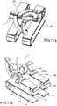
- the figures 11a, 11b illustrate an example of a microrobot according to another aspect of the invention, before the installation of the support and according to two different views, in 3D.
- the figures 11c, 11d illustrate an example of a microrobot according to the invention, with its support and in two different views, in 3D.
- a spherical orientation device 1 comprising a platform 30 to be oriented along two axes of rotation 22, 23 is combined with at least two actuating devices 100, 100 'according to the invention, a first actuating device 100 making it possible to actuate the orientation device 1 so as to orient the platform 30 along a first axis of rotation 22, and a second actuating device 100 making it possible to actuate the orientation device 1 so as to orient the platform 30 along a second axis of rotation 23.
- Such a combination connecting a spherical orientation device 1 and two actuating devices 100, 100 'according to the invention makes it possible to produce a microrobot with spherical parallel kinematics with two degrees of freedom parallel to two degrees of freedom meeting the expected constraints and presented in the introduction to the present application, in particular the precision of orientation, while maintaining the deflections of the desired angles of orientation.
- the actuating devices 100, 100 'according to the invention also make it possible to remotely actuate a spherical orientation device 1, since they are electrically connected, therefore potentially remotely, and they act in bending when they are excited by a tension.
- the fixed point 111 (resp 111 ') and the fixed pivot points 112, 113 (resp 112', 113 ') necessary for the operation of the actuating device 100 (resp 100') according to the invention form part of the support 50.
- Said support 50 is also configured to create the fixed points 2a and 2b for the spherical orientation device 1, as illustrated in figures 11c and 11d .
- the microrobot 60 thus obtained has a structure of parallel architecture which, unlike a structure of series architecture, can implement flexible joints arranged inside said structure which are not necessarily actuated, that is, ie passive seals. On the contrary, the joints flexible structures in series must all be provided with an actuating device.
- this combination makes it possible to obtain a microrobot whose dimensions are included in a cube of 10 x 10 x 10 mm 3 at most, with details on the pattern of around ten ⁇ m.
- a mirror 31 can be positioned, as illustrated in the figures 11a to 11d .
- the microrobot 60 makes it possible to orient the mirror 31 along the two axes of rotation 22 and 23.
- the electrical connections can be fixed on the support 50, or even be included all or part of the interior of the support, in order to minimize the volume occupied by the microrobot 60 and its electrical connections.
- kinematic structures other than spherical can be used.
- any kinematic structure which can, at least, orient a platform on two coplanar axes. Parallel and series structures are possible.
- the microrobot according to the invention can be used in the field of microsurgery as the terminal system of a flexible endoscope 70. If it is the specific field of phonosurgery, the endoscope is called a larynscope .
- the microrobot carrying the mirror 31 in general a microrobot comprising a platform, which supports a mirror, is used to orient a laser beam 71.
- the initial orientation of the mirror 31 must be calculated during the geometric design of the device.
- orientation 1 in order to reflect the laser beam 71 in the directions and according to the desired angular movement, corresponding to the area to be treated 80.
- a laser beam 71a will be delivered by an optical fiber 72 from the outside to the distal end of the endoscope 70.
- the optical fiber generates a laser beam 71a which is reflected by a prism. 73 to return a laser beam 71b.
- the mirror 31 is arranged so as to focus and then to reflect the laser beam 71b to return a laser beam 71c.
- the orientation of the plane mirror is guided by the microrobot.
- the microrobot 60 directs the laser beam 71c on the areas to be treated 80, for example on the vocal cords.
- the microrobot according to the invention makes it possible to meet the need for a small device (which can enter the throat), which can scan a laser beam according to a defined angular range and according to two degrees of freedom, with a large speed (so as not to stay in one position for a long time) and a fine enough resolution (to distinguish healthy cells from malignant cells).
- the microrobot makes it possible to accommodate at least one viewing system, for example a camera, in order to verify the position of the laser beam, preferably the laser beam 71b, before it reaches the zone 80 to be treated.
- at least one viewing system for example a camera
- the invention can find many applications, in particular for actuating a platform, said platform being able to accommodate a mirror for reflecting a laser beam.
- the laser beam to be thus used for marking and / or laser engraving, for 3D scanning, in the field of (micro) robotics (laser vision for example), in the field of telecommunications (for example for an attenuator variable optics or an optical switch), or for medical applications (minimally invasive endoscopic surgery, optical exploration with or without biopsy, etc.).
- microrobot according to the invention can be used on drones, autonomous vehicles and more generally on mobile robotics.
- one application of the microrobot is to miniaturize and make mobile scanning devices for LIDAR (Light Detection and Ranging).
- LIDAR Light Detection and Ranging
- a device scans the surface of a land with a laser to characterize its relief.
- the distance and the profile of the elements which appear on the surface of the ground (houses, trees, cars, water, ...) is calculated by interferometry.
- the microrobot according to the invention can advantageously carry out such a scan.
Landscapes
- Engineering & Computer Science (AREA)
- Robotics (AREA)
- Mechanical Engineering (AREA)
- Health & Medical Sciences (AREA)
- Life Sciences & Earth Sciences (AREA)
- Surgery (AREA)
- Heart & Thoracic Surgery (AREA)
- Biomedical Technology (AREA)
- Nuclear Medicine, Radiotherapy & Molecular Imaging (AREA)
- Medical Informatics (AREA)
- Molecular Biology (AREA)
- Animal Behavior & Ethology (AREA)
- General Health & Medical Sciences (AREA)
- Public Health (AREA)
- Veterinary Medicine (AREA)
- Micromachines (AREA)
- Manipulator (AREA)
Claims (20)
- Bewegungsverstärkende Betätigungsvorrichtung (100), dadurch gekennzeichnet, dass sie aufweist:- einen ersten Träger (101), der ein piezoelektrisches Element (P) aufweist, das in der Lage ist, sich entlang einer Hauptachse (124) zu biegen, wenn Spannung darauf aufgebracht wird, und der geeignet ist, an einem ersten Ende (101a) an einem Festpunkt (111) angebracht zu werden;- einen zweiten Träger (102), der ein piezoelektrisches Element aufweist, das in der Lage ist, sich entlang der Hauptachse (124) zu biegen, wenn Spannung darauf aufgebracht wird, und der ein erstes Ende (102a) und ein zweites Ende (102b) aufweist;- ein erstes Gelenk (131), welches aufweist:- ein erstes Teil (131a), das entlang einer zu der Hauptachse (124) senkrechten Achse flexibel ist und an dem zweiten Ende (101b) des ersten Trägers mit dem ersten Träger (101) verbunden ist,- ein zweites Teil (131b), das entlang einer zu der Hauptachse (124) senkrechten Achse flexibel ist und an dem ersten Ende (102a) des zweiten Trägers mit dem zweiten Träger (102) verbunden ist,- ein erstes starres Teil (131d), welches das erste und das zweite flexible Teil (131a, 131b) miteinander verbindet,- ein zweites starres Teil (131e), das gegen einen zweiten Festpunkt (112) positionierbar ist,- ein entlang einer zu der Hauptachse (124) senkrechten Achse flexibles drittes Teil (131c), das den zweiten Träger (102) mit dem zweiten starren Teil (131e) an einem Schwenkpunkt (102c) des zweiten Trägers (102) derart verbindet, dass die von dem zweiten starren Teil (131e) und dem zweiten Träger (102) gebildete Einheit einen Hebel um den Schwenkpunkt (102c) bildet,
wobei die flexiblen (131a, 131b, 131c) und die starren Teile (131d, 131e) die Bestandteile eines einstückigen Teils sind. - Bewegungsverstärkende Betätigungsvorrichtung (100) nach Anspruch 1, ferner aufweisend:- einen dritten Träger (103), der ein piezoelektrisches Element (P) aufweist, das in der Lage ist, sich entlang der Hauptachse (124) zu biegen, wenn Spannung darauf aufgebracht wird, und der ein erstes Ende (193a) und ein zweites Ende (103b) aufweist;- ein zweites Gelenk (132), welches aufweist:- ein erstes Teil (132a), das entlang einer zu der Hauptachse (124) senkrechten Achse flexibel ist und an dem zweiten Ende (102b) des zweiten Trägers mit dem zweiten Träger (102) verbunden ist,- ein zweites Teil (132b), das entlang einer zu der Hauptachse (124) senkrechten Achse flexibel ist und an dem ersten Ende (103a) des dritten Trägers mit dem dritten Träger (103) verbunden ist,- ein erstes starres Teil (132d), welches das erste und das zweite flexible Teil (132a, 132b) miteinander verbindet,- ein zweites starres Teil (132e), das gegen einen dritten Festpunkt (113) positionierbar ist,- ein entlang einer zu der Hauptachse (124) senkrechten Achse flexibles drittes Teil (132c), das den dritten Träger (103) mit dem zweiten starren Teil (132e) an einem Schwenkpunkt (103c) des dritten Trägers (102) derart verbindet, dass die von dem zweiten starren Teil (132e) und dem zweiten Träger (132) gebildete Einheit einen Hebel um den Schwenkpunkt (103c) bildet,
wobei die flexiblen (132a, 132b, 132c) und die starren Teile (132d, 132e) die Bestandteile eines einstückigen Teils sind. - Bewegungsverstärkende Betätigungsvorrichtung (100) nach Anspruch 1 oder 2, welche aufweist:- einen ersten Träger (101), der ein piezoelektrisches Element (P) aufweist, das in der Lage ist, sich entlang einer Hauptachse (124) zu biegen, wenn Spannung darauf aufgebracht wird, und der geeignet ist, an einem ersten Ende (101a) an einem Festpunkt (111) angebracht zu werden;- N weitere Träger (10M), wobei N größer oder gleich 2 ist und M zwischen 2 und N variiert, wobei jeder M-te Träger ein piezoelektrisches Element (P), das in der Lage ist, sich entlang einer Hauptachse (124) zu biegen, wenn Spannung darauf aufgebracht wird, und ein erstes Ende (10Ma) und ein zweites Ende (10Mb) aufweist; wobei der N-te Träger (10N) ein freies zweites Ende (10Nb) aufweist;- X Gelenke (13Y), wobei X gleich N-1 und Y gleich M-1 ist, wobei jedes Y-te Gelenk (13Y) aufweist:- ein erstes Teil (13Ya), das entlang einer zu der Hauptachse (124) senkrechten Achse flexibel ist und an dem zweiten Ende (10Yb) des Y-ten Trägers mit dem Y-ten Träger (10Y) verbunden ist,- ein zweites Teil (13Yb), das entlang einer zu der Hauptachse (124) senkrechten Achse flexibel ist und an dem M-ten Ende (10Ma) des M-ten Trägers mit dem M-ten Träger (10M) verbunden ist,- ein erstes starres Teil (13Yd), welches das erste und das zweite flexible Teil miteinander verbindet,- ein zweites starres Teil (13Ye), das gegen einen M-ten Festpunkt (11M) positionierbar ist,- ein entlang einer zu der Hauptachse (124) senkrechten Achse flexibles drittes Teil (13Yc), das den M-ten Träger (10M) mit dem zweiten starren Teil (13Ye) an einem Schwenkpunkt (10Mc) des M-ten Trägers (10M) derart verbindet, dass die von dem zweiten starren Teil (13Ye) und dem M-ten Träger (13M) gebildete Einheit einen Hebel um den Schwenkpunkt (10Mc) bildet,
wobei die flexiblen (13Ya, 13Yb, 13Yc) und die starren Teile (13Yd, 13Ye) die Bestandteile eines einstückigen Teils sind. - Bewegungsverstärkende Betätigungsvorrichtung (100) nach Anspruch 3, bei welcher mindestens ein Y-tes Gelenk (13Y) ferner ein drittes (13Yf) und ein viertes starres Teil (13Yg) aufweist, welche mit den anderen Teilen des Gelenks ein einstückiges Teil bilden:- wobei das dritte starre Teil (13Yf) die Verbindung zwischen dem ersten flexiblen Teil (13Ya) des Y-ten Gelenks (13Y) und dem Y-ten Träger (10Y) bildet,- wobei das vierte starre Teil (13Yg) die Verbindung zwischen dem zweiten flexiblen Teil (13Yb) des Y-ten Gelenks (13Y) und dem M-ten Träger (10M) bildet.
- Bewegungsverstärkende Betätigungsvorrichtung (100) nach einem der vorangehenden Ansprüche, bei welcher die flexiblen Teile mindestens eines Y-ten Gelenks (13Y) zueinander parallele und zu der Hauptachse (124) senkrechte Gelenkachsen aufweisen.
- Bewegungsverstärkende Betätigungsvorrichtung (100) nach einem der vorangehenden Ansprüche, bei welcher das piezoelektrische Element (P) Titanat-Bleizirkonat aufweist.
- Bewegungsverstärkende Betätigungsvorrichtung (100) nach einem der vorangehenden Ansprüche, bei welcher mindestens ein Träger (10M) eine bimorphe Struktur aufweist.
- Mikroroboter (60) mit paralleler sphärischer Kinematik mit zwei Freiheitsgraden, welcher aufweist:- eine Ausrichtvorrichtung mit zwei Freiheitsgraden, welche eine entlang einer ersten (22) und einer zweiten Drehachse (23) in Bezug auf eine feste Basis (2) ausrichtbare Plattform (30), einen ersten Betätigungsarm (4) und einen zweiten Betätigungsarm (8) aufweist;- eine erste und eine zweite bewegungsverstärkende Betätigungsvorrichtung (100, 100') nach einem der Ansprüche 1 bis 7;wobei die erste Betätigungsvorrichtung (100) mit dem ersten Betätigungsarm (4) derart verbunden ist, dass sie an diesen eine erste Translationsverschiebung in Bezug auf die feste Basis (2) überträgt, um die Plattform (30) entlang der ersten Achse (22) drehend anzutreiben, und
wobei die zweite Betätigungsvorrichtung (100') mit dem zweiten Betätigungsarm (8) derart verbunden ist, dass sie an diesen eine zweite Translationsverschiebung in Bezug auf die feste Basis (2) überträgt, um die Plattform (30) entlang der zweiten Achse (23) drehend anzutreiben. - Mikroroboter (60) nach Anspruch 8, bei welchem die Ausrichtvorrichtung eine sphärische Ausrichtvorrichtung (1) mit zwei Freiheitsgraden ist, welche die Plattform (30) mit zwei Befestigungspunkten (2a, 2b) einer festen Basis (2) derart verbindet, dass sie die Plattform (30) durch Drehen um eine erste Achse (22) und eine zweite Achse (23) im Raum ausrichten kann, wobei die beiden Achsen (22, 23) im Wesentlichen senkrecht sind und sich in einem sphärischen Bewegungsmittelpunkt (21) kreuzen, der sich in dem auszurichtenden Organ (30) befindet, aufweisend:- einen ersten Betätigungsarm (4), der dazu ausgebildet ist, eine Translationsbewegung in Bezug auf die feste Basis (2) durchzuführen und dazu geeignet ist, auf einen ersten Übertragungsarm (5), der mit einem ersten Befestigungspunkt (2a) der festen Basis (2) durch eine entlang der ersten Achse (22) gelenkige flexible Verbindung (6) verbunden ist, eine Drehbewegung in Bezug auf die feste Basis (2) zu übertragen, um an die Plattform (30) eine Drehbewegung entlang der ersten Achse (22) zu übertragen;- einen Mittelarm (12), der mit dem ersten Übertragungsarm (5) durch eine flexible um eine zu der ersten und der zweiten Achse (22) und (23) senkrechte dritte Achse (24) gelenkige Verbindung (13) verbunden ist, und mit der Plattform (30) durch eine flexible Verbindung (14) verbunden ist, um an die Plattform (30) eine Drehbewegung entlang der ersten Achse (22) zu übertragen;- einen zweiten Betätigungsarm (8), der dazu ausgebildet ist, eine Translationsbewegung in Bezug auf die feste Basis (2) durchzuführen und dazu geeignet ist, auf einen zweiten Übertragungsarm (9), der mit einem zweiten Befestigungspunkt (2b) der festen Basis (2) durch eine entlang der zweiten Achse (23) gelenkige flexible Verbindung (10) verbunden ist, eine Drehbewegung in Bezug auf die feste Basis (2) zu übertragen, um an die Plattform (30) eine Drehbewegung entlang der zweiten Achse (23) zu übertragen, wobei der Arm (9) mit der Plattform (30) durch eine entlang der ersten Achse (22) gelenkige flexible Verbindung (15, 16) derart verbunden ist, dass der zweite Übertragungsarm (9) bei der Betätigung des ersten Betätigungsarms (4) nicht entlang der ersten Achse (22) drehend angetrieben wird;wobei die Verbindung (14) zwischen der Plattform (30) und dem Zwischenarm (12) derart entlang der Achse gelenkig ist, dass der Zwischenarm (12) bei der Betätigung des zweiten Betätigungsarms (8) nicht entlang der zweiten Achse (23) drehend angetrieben wird;
und die Arme (4, 5, 8, 9, 12), die flexiblen Verbindungen (6, 10, 13, 14, 15, 16) und die Plattform (30) die Bestandteile eines einstückigen Teils bilden, welches die Vorrichtung bildet, wobei die Arme (4, 5, 8, 9, 12) und die Plattform (30) starre Teile der Vorrichtung (1) sind und die flexiblen Verbindungen (6, 10, 13, 14, 15, 16) flexible Teile sind, die jeweils ein Scharnier entlang einer einzelnen der ersten, zweiten und dritten Achsen (22, 23, 24) bilden und die starren Teile untereinander, mit der festen Basis (2) verbinden. - Mikroroboter (60) nach Anspruch 8 oder 9, bei welchem die starren Teile (4, 5, 8, 9, 12, 30) eine mittlere Schicht (41) aus einem flexiblen Material, wie Polyimid, aufweisen, die sandwichartig zwischen zwei Schichten (42, 43) aus einem starren Material, wie Carbonfaser, gehalten ist, wobei die flexiblen Verbindungen (6, 10, 13, 14, 15, 16) aus der mittleren Schicht zusammengesetzt sind.
- Mikroroboter (60) nach einem der Ansprüche 8 bis 10, bei welchem ein Übertragungsarm oder -arme (5, 9) und/oder ein Mittelarm (12) einen Kreisbogen bilden.
- Mikroroboter (60) nach einem der Ansprüche 8 bis 11, bei welchem die sphärische Ausrichtvorrichtung (1) ferner eine flexible Verbindung (7) aufweist, die um eine zu der ersten Achse (22) parallele Achse gelenkig ist und zwischen dem ersten Betätigungsarm (4) und dem ersten Übertragungsarm (5) angeordnet ist, und mit den Armen (4, 5, 8, 9, 12), den flexiblen Verbindungen (6, 10, 13, 14, 15, 16) und der Plattform (30) ein einstückiges Teil bildet.
- Mikroroboter (60) nach einem der Ansprüche 8 bis 12, bei welchem der erste Betätigungsarm (4) ein mit der Betätigungsvorrichtung (100) koppelbares erstes Teil (4a) und ein zweites Teil (4b) aufweist, das mit dem ersten Übertragungsarm (5) durch eine um eine zu der ersten Achse (22) parallele Achse gelenkige flexible Verbindung (7) verbunden ist, wobei das erste und das zweite Teil (4a) und (4b) durch eine entlang einer zu der ersten Achse (22) parallelen Achse gelenkige flexible Verbindung verbunden sind, und mit den Armen (4, 5, 8, 9, 12), den flexiblen Verbindungen (6, 10, 13, 14, 15, 16) und der Plattform (30) ein einstückiges Teil bilden.
- Mikroroboter (60) nach einem der Ansprüche 8 bis 13, bei welchem die sphärische Ausrichtvorrichtung (1) ferner eine flexible Verbindung (11) aufweist, welche den zweiten Betätigungsarm (8) und den zweiten Betätigungsarm (9) miteinander verbindet, um eine zu der zweiten Achse (23) parallele Achse gelenkig ist, und mit den Armen (4, 5, 8, 9, 12), den flexiblen Verbindungen (6, 10, 13, 14, 15, 16) und der Plattform (30) ein einstückiges Teil bildet.
- Mikroroboter (60) nach einem der Ansprüche 8 bis 14, bei welchem die sphärische Ausrichtvorrichtung /1) nach einem der Ansprüche 1 bis 5 ferner eine doppelte flexible Verbindung (19) vom Kardantyp aufweist, welche den zweiten Betätigungsarm (8) und den zweiten Übertragungsarm (9) verbindet, um eine zu der ersten Achse (22) parallel Achse und eine zu der zweiten Achse (23) parallele Achse gelenkig ist, und mit den Armen (4, 5, 8, 9, 12), den flexiblen Verbindungen (6, 10, 13, 14, 15, 16) und der Plattform (30) ein einstückiges Teil bildet.
- Mikroroboter (60) nach einem der Ansprüche 8 bis 15, bei welchem der zweite Betätigungsarm (8) ein mit dem Betätigungselement (100') koppelbares erstes Teil (8a) und ein zweites Teil (8b) aufweist, das mit dem zweiten Übertragungsarm (9) durch eine einfache flexible Verbindung (11) oder eine doppelte flexible Verbindung (19) verbunden ist, wobei das erste und das zweite Teil (8a) und (8b) durch eine doppelte flexible Verbindung (18) vom Kardantyp verbunden sind, die um eine zu der ersten Achse (22) parallele Achse und eine zu der zweiten Achse (23) parallele Achse gelenkig ist, und mit den Armen (4, 5, 8, 9, 12), den flexiblen Verbindungen (6, 10, 13, 14, 15, 16) und der Plattform (30) ein einstückiges Teil bilden.
- Mikroroboter (60) nach einem der Ansprüche 8 bis 16, welcher ferner eine Stütze (50) aufweist, die dazu ausgebildet ist, Festpunkte der Betätigungsvorrichtungen (100, 100') zu bilden.
- Mikroroboter (60) nach einem der Ansprüche 8 bis 17, bei welchem die Plattform (30) einen Spiegel (31) stützt.
- Mikroroboter (60) nach Anspruch 18, bei welchem der Spiegel (31) derart angeordnet ist, einen Laserstrahl (71) zu reflektieren.
- Mikroroboter (60) nach Anspruch 19, welcher ferner eine Vorrichtung zur Visualisierung eines Punkts des Laserstrahls (71) aufweist, die auf einer Fläche positioniert ist.
Applications Claiming Priority (2)
| Application Number | Priority Date | Filing Date | Title |
|---|---|---|---|
| FR1757122A FR3069739B1 (fr) | 2017-07-27 | 2017-07-27 | Dispositif d'actionnement amplificateur de mouvement |
| PCT/EP2018/070462 WO2019020804A1 (fr) | 2017-07-27 | 2018-07-27 | Dispositif d'actionnement amplificateur de mouvement |
Publications (2)
| Publication Number | Publication Date |
|---|---|
| EP3659189A1 EP3659189A1 (de) | 2020-06-03 |
| EP3659189B1 true EP3659189B1 (de) | 2021-05-26 |
Family
ID=60923561
Family Applications (1)
| Application Number | Title | Priority Date | Filing Date |
|---|---|---|---|
| EP18753092.8A Active EP3659189B1 (de) | 2017-07-27 | 2018-07-27 | Bewegungsverstärkende betätigungsvorrichtung |
Country Status (4)
| Country | Link |
|---|---|
| US (1) | US11463020B2 (de) |
| EP (1) | EP3659189B1 (de) |
| FR (1) | FR3069739B1 (de) |
| WO (1) | WO2019020804A1 (de) |
Families Citing this family (2)
| Publication number | Priority date | Publication date | Assignee | Title |
|---|---|---|---|---|
| FR3130124B1 (fr) * | 2021-12-09 | 2023-12-08 | Univ Franche Comte | Dispositif d’orientation |
| CN115570598B (zh) * | 2022-12-08 | 2023-03-10 | 浙江大学 | 微型并联机器人及平面化设计制造方法 |
Family Cites Families (7)
| Publication number | Priority date | Publication date | Assignee | Title |
|---|---|---|---|---|
| DD128025A1 (de) * | 1976-08-17 | 1977-10-26 | Volker Flechtner | Piezoelektrischer schrittmotor |
| US5219347A (en) * | 1991-12-24 | 1993-06-15 | Laser Engineering, Inc. | Decoupled dual-beam control system |
| GB9704769D0 (en) * | 1997-03-07 | 1997-04-23 | Powerbreaker Plc | Low component count release mechanism |
| US6798120B1 (en) * | 2001-10-31 | 2004-09-28 | The Regents Of The University Of California | Apparatus and method for manipulation of an object |
| FR2850217A1 (fr) | 2003-01-17 | 2004-07-23 | Cedrat Technologies | Actionneur piezoactif a deplacement amplifie amorti |
| JP5191939B2 (ja) * | 2009-03-31 | 2013-05-08 | スタンレー電気株式会社 | 光偏向器用アクチュエータ装置 |
| DE102010021867A1 (de) * | 2010-05-28 | 2011-12-01 | Eurocopter Deutschland Gmbh | Kraftgenerator zur Anbringung an einer Struktur |
-
2017
- 2017-07-27 FR FR1757122A patent/FR3069739B1/fr not_active Expired - Fee Related
-
2018
- 2018-07-27 EP EP18753092.8A patent/EP3659189B1/de active Active
- 2018-07-27 WO PCT/EP2018/070462 patent/WO2019020804A1/fr not_active Ceased
- 2018-07-27 US US16/634,375 patent/US11463020B2/en active Active
Non-Patent Citations (1)
| Title |
|---|
| None * |
Also Published As
| Publication number | Publication date |
|---|---|
| FR3069739B1 (fr) | 2019-08-30 |
| EP3659189A1 (de) | 2020-06-03 |
| WO2019020804A1 (fr) | 2019-01-31 |
| FR3069739A1 (fr) | 2019-02-01 |
| US11463020B2 (en) | 2022-10-04 |
| US20210114200A1 (en) | 2021-04-22 |
Similar Documents
| Publication | Publication Date | Title |
|---|---|---|
| US8700134B2 (en) | Cantilever-based MEMS optical scanning apparatus, system and method | |
| FR3015694A1 (fr) | Dispositif optique a variation de focale | |
| EP2144105A2 (de) | Vorrichtung zum Korrigieren der optischen Fehler eines Teleskopspiegels | |
| WO2001080935A1 (fr) | Dispositif de positionnement, d'exploration et/ou d'intervention notamment dans le domaine de l'endoscopie et/ou de la chirurgie mini-invasive | |
| EP0802439A1 (de) | Optomechanische Mikrovorrichtung und optomechanischer Mikro-Strahlablenker unter Verwendung dserselben | |
| WO2015091836A1 (fr) | Dispositif optique pour la stabilisation d'images | |
| EP2042076A2 (de) | Schwenkbare, bewegliche Struktur vom Typ Katheter oder Endoskop | |
| KR20140042464A (ko) | 광학 줌 프로브 | |
| FR3069739B1 (fr) | Dispositif d'actionnement amplificateur de mouvement | |
| EP3743025B1 (de) | Vorrichtung zum schneiden eines menschlichen oder tierischen gewebes mit einem optischen koppler | |
| JP7542549B2 (ja) | 光学ビーム合成のためのデバイスおよび方法 | |
| JP2017514439A (ja) | 圧電アクチュエータのための一体型前負荷機構 | |
| EP1395167A1 (de) | Aktive schwenkbare rohrstruktur und daraus gebildetes endoskop | |
| EP1036433A1 (de) | Elektrostatischer microantrieb, dreidimensionaler aktive mikrokatheter und verfahren zur herstellung | |
| JP2006516761A (ja) | 軸外可変焦点および収差制御鏡および方法 | |
| KR20140089129A (ko) | 광학 줌 프로브 | |
| EP3037381A1 (de) | Vorrichtung zur umwandlung einer bewegung aus der ebene in eine bewegung in der ebene bzw. umgekehrt | |
| EP3764148A1 (de) | Scanner mit optischer netzeinheit mit mobiler phasensteuerung | |
| WO2023104700A1 (fr) | Dispositif d'orientation | |
| Kikuchi et al. | Piezolectric 2D micro scanner for minimally invasive therapy fabricated using femtosecond laser ablation | |
| WO2004037096A1 (fr) | Microcapteur d’effort en cisaillement et outil terminal d’instrument chirurgical | |
| EP1583461B1 (de) | Longitudinale orientierbare struktur | |
| FR3095910A1 (fr) | Moteur piézoélectrique à onde progressive à résolution micrométrique | |
| CN114615945A (zh) | 紧凑型激光操控末端执行器 | |
| EP3933483B1 (de) | Optischer scanner |
Legal Events
| Date | Code | Title | Description |
|---|---|---|---|
| STAA | Information on the status of an ep patent application or granted ep patent |
Free format text: STATUS: UNKNOWN |
|
| STAA | Information on the status of an ep patent application or granted ep patent |
Free format text: STATUS: THE INTERNATIONAL PUBLICATION HAS BEEN MADE |
|
| PUAI | Public reference made under article 153(3) epc to a published international application that has entered the european phase |
Free format text: ORIGINAL CODE: 0009012 |
|
| STAA | Information on the status of an ep patent application or granted ep patent |
Free format text: STATUS: REQUEST FOR EXAMINATION WAS MADE |
|
| 17P | Request for examination filed |
Effective date: 20200210 |
|
| AK | Designated contracting states |
Kind code of ref document: A1 Designated state(s): AL AT BE BG CH CY CZ DE DK EE ES FI FR GB GR HR HU IE IS IT LI LT LU LV MC MK MT NL NO PL PT RO RS SE SI SK SM TR |
|
| AX | Request for extension of the european patent |
Extension state: BA ME |
|
| RIN1 | Information on inventor provided before grant (corrected) |
Inventor name: RAKOTONDRABE, MICKY Inventor name: TAMADAZTE, BRAHIM Inventor name: RABENOROSOA, KANTY Inventor name: BOUDERLIQUE, CLEMENT Inventor name: ANDREFF, NICOLAS Inventor name: LESCANO, SERGIO |
|
| DAV | Request for validation of the european patent (deleted) | ||
| DAX | Request for extension of the european patent (deleted) | ||
| GRAP | Despatch of communication of intention to grant a patent |
Free format text: ORIGINAL CODE: EPIDOSNIGR1 |
|
| STAA | Information on the status of an ep patent application or granted ep patent |
Free format text: STATUS: GRANT OF PATENT IS INTENDED |
|
| INTG | Intention to grant announced |
Effective date: 20201214 |
|
| GRAS | Grant fee paid |
Free format text: ORIGINAL CODE: EPIDOSNIGR3 |
|
| GRAA | (expected) grant |
Free format text: ORIGINAL CODE: 0009210 |
|
| STAA | Information on the status of an ep patent application or granted ep patent |
Free format text: STATUS: THE PATENT HAS BEEN GRANTED |
|
| AK | Designated contracting states |
Kind code of ref document: B1 Designated state(s): AL AT BE BG CH CY CZ DE DK EE ES FI FR GB GR HR HU IE IS IT LI LT LU LV MC MK MT NL NO PL PT RO RS SE SI SK SM TR |
|
| REG | Reference to a national code |
Ref country code: GB Ref legal event code: FG4D Free format text: NOT ENGLISH |
|
| REG | Reference to a national code |
Ref country code: CH Ref legal event code: EP |
|
| REG | Reference to a national code |
Ref country code: AT Ref legal event code: REF Ref document number: 1397121 Country of ref document: AT Kind code of ref document: T Effective date: 20210615 |
|
| REG | Reference to a national code |
Ref country code: DE Ref legal event code: R096 Ref document number: 602018017764 Country of ref document: DE |
|
| REG | Reference to a national code |
Ref country code: IE Ref legal event code: FG4D Free format text: LANGUAGE OF EP DOCUMENT: FRENCH |
|
| REG | Reference to a national code |
Ref country code: LT Ref legal event code: MG9D |
|
| REG | Reference to a national code |
Ref country code: AT Ref legal event code: MK05 Ref document number: 1397121 Country of ref document: AT Kind code of ref document: T Effective date: 20210526 |
|
| PG25 | Lapsed in a contracting state [announced via postgrant information from national office to epo] |
Ref country code: FI Free format text: LAPSE BECAUSE OF FAILURE TO SUBMIT A TRANSLATION OF THE DESCRIPTION OR TO PAY THE FEE WITHIN THE PRESCRIBED TIME-LIMIT Effective date: 20210526 Ref country code: HR Free format text: LAPSE BECAUSE OF FAILURE TO SUBMIT A TRANSLATION OF THE DESCRIPTION OR TO PAY THE FEE WITHIN THE PRESCRIBED TIME-LIMIT Effective date: 20210526 Ref country code: LT Free format text: LAPSE BECAUSE OF FAILURE TO SUBMIT A TRANSLATION OF THE DESCRIPTION OR TO PAY THE FEE WITHIN THE PRESCRIBED TIME-LIMIT Effective date: 20210526 Ref country code: AT Free format text: LAPSE BECAUSE OF FAILURE TO SUBMIT A TRANSLATION OF THE DESCRIPTION OR TO PAY THE FEE WITHIN THE PRESCRIBED TIME-LIMIT Effective date: 20210526 Ref country code: BG Free format text: LAPSE BECAUSE OF FAILURE TO SUBMIT A TRANSLATION OF THE DESCRIPTION OR TO PAY THE FEE WITHIN THE PRESCRIBED TIME-LIMIT Effective date: 20210826 |
|
| REG | Reference to a national code |
Ref country code: NL Ref legal event code: MP Effective date: 20210526 |
|
| PG25 | Lapsed in a contracting state [announced via postgrant information from national office to epo] |
Ref country code: PT Free format text: LAPSE BECAUSE OF FAILURE TO SUBMIT A TRANSLATION OF THE DESCRIPTION OR TO PAY THE FEE WITHIN THE PRESCRIBED TIME-LIMIT Effective date: 20210927 Ref country code: RS Free format text: LAPSE BECAUSE OF FAILURE TO SUBMIT A TRANSLATION OF THE DESCRIPTION OR TO PAY THE FEE WITHIN THE PRESCRIBED TIME-LIMIT Effective date: 20210526 Ref country code: SE Free format text: LAPSE BECAUSE OF FAILURE TO SUBMIT A TRANSLATION OF THE DESCRIPTION OR TO PAY THE FEE WITHIN THE PRESCRIBED TIME-LIMIT Effective date: 20210526 Ref country code: PL Free format text: LAPSE BECAUSE OF FAILURE TO SUBMIT A TRANSLATION OF THE DESCRIPTION OR TO PAY THE FEE WITHIN THE PRESCRIBED TIME-LIMIT Effective date: 20210526 Ref country code: LV Free format text: LAPSE BECAUSE OF FAILURE TO SUBMIT A TRANSLATION OF THE DESCRIPTION OR TO PAY THE FEE WITHIN THE PRESCRIBED TIME-LIMIT Effective date: 20210526 Ref country code: NO Free format text: LAPSE BECAUSE OF FAILURE TO SUBMIT A TRANSLATION OF THE DESCRIPTION OR TO PAY THE FEE WITHIN THE PRESCRIBED TIME-LIMIT Effective date: 20210826 Ref country code: IS Free format text: LAPSE BECAUSE OF FAILURE TO SUBMIT A TRANSLATION OF THE DESCRIPTION OR TO PAY THE FEE WITHIN THE PRESCRIBED TIME-LIMIT Effective date: 20210926 Ref country code: GR Free format text: LAPSE BECAUSE OF FAILURE TO SUBMIT A TRANSLATION OF THE DESCRIPTION OR TO PAY THE FEE WITHIN THE PRESCRIBED TIME-LIMIT Effective date: 20210827 |
|
| PG25 | Lapsed in a contracting state [announced via postgrant information from national office to epo] |
Ref country code: NL Free format text: LAPSE BECAUSE OF FAILURE TO SUBMIT A TRANSLATION OF THE DESCRIPTION OR TO PAY THE FEE WITHIN THE PRESCRIBED TIME-LIMIT Effective date: 20210526 |
|
| PG25 | Lapsed in a contracting state [announced via postgrant information from national office to epo] |
Ref country code: RO Free format text: LAPSE BECAUSE OF FAILURE TO SUBMIT A TRANSLATION OF THE DESCRIPTION OR TO PAY THE FEE WITHIN THE PRESCRIBED TIME-LIMIT Effective date: 20210526 Ref country code: SM Free format text: LAPSE BECAUSE OF FAILURE TO SUBMIT A TRANSLATION OF THE DESCRIPTION OR TO PAY THE FEE WITHIN THE PRESCRIBED TIME-LIMIT Effective date: 20210526 Ref country code: CZ Free format text: LAPSE BECAUSE OF FAILURE TO SUBMIT A TRANSLATION OF THE DESCRIPTION OR TO PAY THE FEE WITHIN THE PRESCRIBED TIME-LIMIT Effective date: 20210526 Ref country code: DK Free format text: LAPSE BECAUSE OF FAILURE TO SUBMIT A TRANSLATION OF THE DESCRIPTION OR TO PAY THE FEE WITHIN THE PRESCRIBED TIME-LIMIT Effective date: 20210526 Ref country code: SK Free format text: LAPSE BECAUSE OF FAILURE TO SUBMIT A TRANSLATION OF THE DESCRIPTION OR TO PAY THE FEE WITHIN THE PRESCRIBED TIME-LIMIT Effective date: 20210526 Ref country code: EE Free format text: LAPSE BECAUSE OF FAILURE TO SUBMIT A TRANSLATION OF THE DESCRIPTION OR TO PAY THE FEE WITHIN THE PRESCRIBED TIME-LIMIT Effective date: 20210526 Ref country code: ES Free format text: LAPSE BECAUSE OF FAILURE TO SUBMIT A TRANSLATION OF THE DESCRIPTION OR TO PAY THE FEE WITHIN THE PRESCRIBED TIME-LIMIT Effective date: 20210526 |
|
| REG | Reference to a national code |
Ref country code: CH Ref legal event code: PL |
|
| REG | Reference to a national code |
Ref country code: DE Ref legal event code: R097 Ref document number: 602018017764 Country of ref document: DE |
|
| PLBE | No opposition filed within time limit |
Free format text: ORIGINAL CODE: 0009261 |
|
| STAA | Information on the status of an ep patent application or granted ep patent |
Free format text: STATUS: NO OPPOSITION FILED WITHIN TIME LIMIT |
|
| PG25 | Lapsed in a contracting state [announced via postgrant information from national office to epo] |
Ref country code: MC Free format text: LAPSE BECAUSE OF FAILURE TO SUBMIT A TRANSLATION OF THE DESCRIPTION OR TO PAY THE FEE WITHIN THE PRESCRIBED TIME-LIMIT Effective date: 20210526 |
|
| REG | Reference to a national code |
Ref country code: BE Ref legal event code: MM Effective date: 20210731 |
|
| PG25 | Lapsed in a contracting state [announced via postgrant information from national office to epo] |
Ref country code: LI Free format text: LAPSE BECAUSE OF NON-PAYMENT OF DUE FEES Effective date: 20210731 Ref country code: CH Free format text: LAPSE BECAUSE OF NON-PAYMENT OF DUE FEES Effective date: 20210731 |
|
| 26N | No opposition filed |
Effective date: 20220301 |
|
| PG25 | Lapsed in a contracting state [announced via postgrant information from national office to epo] |
Ref country code: IS Free format text: LAPSE BECAUSE OF FAILURE TO SUBMIT A TRANSLATION OF THE DESCRIPTION OR TO PAY THE FEE WITHIN THE PRESCRIBED TIME-LIMIT Effective date: 20210926 Ref country code: LU Free format text: LAPSE BECAUSE OF NON-PAYMENT OF DUE FEES Effective date: 20210727 Ref country code: AL Free format text: LAPSE BECAUSE OF FAILURE TO SUBMIT A TRANSLATION OF THE DESCRIPTION OR TO PAY THE FEE WITHIN THE PRESCRIBED TIME-LIMIT Effective date: 20210526 |
|
| PG25 | Lapsed in a contracting state [announced via postgrant information from national office to epo] |
Ref country code: IT Free format text: LAPSE BECAUSE OF FAILURE TO SUBMIT A TRANSLATION OF THE DESCRIPTION OR TO PAY THE FEE WITHIN THE PRESCRIBED TIME-LIMIT Effective date: 20210526 Ref country code: IE Free format text: LAPSE BECAUSE OF NON-PAYMENT OF DUE FEES Effective date: 20210727 Ref country code: BE Free format text: LAPSE BECAUSE OF NON-PAYMENT OF DUE FEES Effective date: 20210731 |
|
| REG | Reference to a national code |
Ref country code: DE Ref legal event code: R079 Ref document number: 602018017764 Country of ref document: DE Free format text: PREVIOUS MAIN CLASS: H01L0041090000 Ipc: H10N0030200000 |
|
| PG25 | Lapsed in a contracting state [announced via postgrant information from national office to epo] |
Ref country code: CY Free format text: LAPSE BECAUSE OF FAILURE TO SUBMIT A TRANSLATION OF THE DESCRIPTION OR TO PAY THE FEE WITHIN THE PRESCRIBED TIME-LIMIT Effective date: 20210526 |
|
| PG25 | Lapsed in a contracting state [announced via postgrant information from national office to epo] |
Ref country code: HU Free format text: LAPSE BECAUSE OF FAILURE TO SUBMIT A TRANSLATION OF THE DESCRIPTION OR TO PAY THE FEE WITHIN THE PRESCRIBED TIME-LIMIT; INVALID AB INITIO Effective date: 20180727 |
|
| PG25 | Lapsed in a contracting state [announced via postgrant information from national office to epo] |
Ref country code: MK Free format text: LAPSE BECAUSE OF FAILURE TO SUBMIT A TRANSLATION OF THE DESCRIPTION OR TO PAY THE FEE WITHIN THE PRESCRIBED TIME-LIMIT Effective date: 20210526 |
|
| PG25 | Lapsed in a contracting state [announced via postgrant information from national office to epo] |
Ref country code: MT Free format text: LAPSE BECAUSE OF FAILURE TO SUBMIT A TRANSLATION OF THE DESCRIPTION OR TO PAY THE FEE WITHIN THE PRESCRIBED TIME-LIMIT Effective date: 20210526 |
|
| PGFP | Annual fee paid to national office [announced via postgrant information from national office to epo] |
Ref country code: DE Payment date: 20250825 Year of fee payment: 8 |
|
| PGFP | Annual fee paid to national office [announced via postgrant information from national office to epo] |
Ref country code: GB Payment date: 20250729 Year of fee payment: 8 |
|
| PGFP | Annual fee paid to national office [announced via postgrant information from national office to epo] |
Ref country code: FR Payment date: 20250729 Year of fee payment: 8 |
|
| PG25 | Lapsed in a contracting state [announced via postgrant information from national office to epo] |
Ref country code: TR Free format text: LAPSE BECAUSE OF FAILURE TO SUBMIT A TRANSLATION OF THE DESCRIPTION OR TO PAY THE FEE WITHIN THE PRESCRIBED TIME-LIMIT Effective date: 20210526 |