EP3659219B1 - Halter für schleifringbürsten - Google Patents
Halter für schleifringbürsten Download PDFInfo
- Publication number
- EP3659219B1 EP3659219B1 EP19746108.0A EP19746108A EP3659219B1 EP 3659219 B1 EP3659219 B1 EP 3659219B1 EP 19746108 A EP19746108 A EP 19746108A EP 3659219 B1 EP3659219 B1 EP 3659219B1
- Authority
- EP
- European Patent Office
- Prior art keywords
- brush
- lever
- mount
- base
- pivot
- Prior art date
- Legal status (The legal status is an assumption and is not a legal conclusion. Google has not performed a legal analysis and makes no representation as to the accuracy of the status listed.)
- Active
Links
Images




Classifications
-
- H—ELECTRICITY
- H01—ELECTRIC ELEMENTS
- H01R—ELECTRICALLY-CONDUCTIVE CONNECTIONS; STRUCTURAL ASSOCIATIONS OF A PLURALITY OF MUTUALLY-INSULATED ELECTRICAL CONNECTING ELEMENTS; COUPLING DEVICES; CURRENT COLLECTORS
- H01R39/00—Rotary current collectors, distributors or interrupters
- H01R39/02—Details for dynamo electric machines
- H01R39/38—Brush holders
- H01R39/381—Brush holders characterised by the application of pressure to brush
-
- H—ELECTRICITY
- H01—ELECTRIC ELEMENTS
- H01R—ELECTRICALLY-CONDUCTIVE CONNECTIONS; STRUCTURAL ASSOCIATIONS OF A PLURALITY OF MUTUALLY-INSULATED ELECTRICAL CONNECTING ELEMENTS; COUPLING DEVICES; CURRENT COLLECTORS
- H01R39/00—Rotary current collectors, distributors or interrupters
- H01R39/02—Details for dynamo electric machines
- H01R39/18—Contacts for co-operation with commutator or slip-ring, e.g. contact brush
- H01R39/26—Solid sliding contacts, e.g. carbon brush
-
- H—ELECTRICITY
- H01—ELECTRIC ELEMENTS
- H01R—ELECTRICALLY-CONDUCTIVE CONNECTIONS; STRUCTURAL ASSOCIATIONS OF A PLURALITY OF MUTUALLY-INSULATED ELECTRICAL CONNECTING ELEMENTS; COUPLING DEVICES; CURRENT COLLECTORS
- H01R39/00—Rotary current collectors, distributors or interrupters
- H01R39/02—Details for dynamo electric machines
- H01R39/18—Contacts for co-operation with commutator or slip-ring, e.g. contact brush
- H01R39/26—Solid sliding contacts, e.g. carbon brush
- H01R39/27—End caps on carbon brushes to transmit spring pressure
-
- H—ELECTRICITY
- H01—ELECTRIC ELEMENTS
- H01R—ELECTRICALLY-CONDUCTIVE CONNECTIONS; STRUCTURAL ASSOCIATIONS OF A PLURALITY OF MUTUALLY-INSULATED ELECTRICAL CONNECTING ELEMENTS; COUPLING DEVICES; CURRENT COLLECTORS
- H01R39/00—Rotary current collectors, distributors or interrupters
- H01R39/02—Details for dynamo electric machines
- H01R39/38—Brush holders
- H01R39/39—Brush holders wherein the brush is fixedly mounted in the holder
-
- H—ELECTRICITY
- H02—GENERATION; CONVERSION OR DISTRIBUTION OF ELECTRIC POWER
- H02K—DYNAMO-ELECTRIC MACHINES
- H02K5/00—Casings; Enclosures; Supports
- H02K5/04—Casings or enclosures characterised by the shape, form or construction thereof
- H02K5/14—Means for supporting or protecting brushes or brush holders
- H02K5/141—Means for supporting or protecting brushes or brush holders for cooperation with slip-rings
Definitions
- the invention relates to slipring brushes and holders for slipring brushes, specifically for applications where a long lifetime and a high current load are required.
- slipring brushes are preferably used with sliprings for energy transmission or signal transmission as well as collectors of motors or generators.
- a brush holder for holding carbon brushes against the commutator of a DC motor is disclosed.
- the brush is slideably held in a housing and pressed by a spring against the commutator. With increasing wear of the brush, the brush slides downwards through the housing which causes the spring to reduce its length and to reduce the force against the brush. Therefore, the pressure of the slipring brush decreases with time, which leads to changing electrical contact characteristics.
- German patent DE 967 293 discloses a brush for electrical machines, wherein a piece of carbon brush material is pressed against a slipring by means of a spring-loaded lever. To achieve a constant pressure, a long spring and a long lever is required, which makes the brush holder large.
- a brush holder with a pivotable ball mounting of the brush is disclosed in GB 146, 828 .
- the ball mounting enables tilting in two axis and rotation of the brush. This requires concave formed collector rings and convex formed brushed adapted thereto.
- RO 92696 A2 discloses a slipring brush holder, where the brush is pivotable about two axes which are neither parallel nor orthogonal.
- EP 3 364 508 A1 discloses a holder for slipring brushes.
- the problem to be solved by the invention is to provide a holder for slipring brushes which is comparatively compact in size and provides an approximately constant pressure over the lifetime of a brush, independent of the wear of the brush.
- a brush holder comprises a base, a lever, and a brush mount.
- the base is the main body which may be used to mount the brush holder to a brush holder assembly, and which may also bear an electrical contact or connector for electrical connection.
- the base may either be of a conductive or a non-conductive material.
- the base may be made of an insulating material.
- an insulating material like a plastic material requires less weight than a metal body.
- the main function of the base is a mechanical function for supporting and holding the other components of the brush holder.
- the brush mount is a component for holding at least one brush and preferably two brushes.
- Such brushes may be any brushes known in the art, like a sintered graphite or silver-graphite material.
- the brushes may also comprise bundles of wires or other suitable materials or a sintered carbon material.
- There may be also only one brush like a foam metal brush or a plurality of such brushes.
- the brush mount comprises a conductive material to improve conduction of electrical current to the brushes. If desired, here also an insulating material may be used.
- the brushes on a single brush mount run on the same sliding track. Therefore, they should be electrically connected, which may best be done by using a conductive material of the brush mount.
- the brush mount itself or the brushes at the brush mount may be electrically contacted by a litz wire or any other flexible wire which may guide the current to and through the brushes.
- a lever is provided to mechanically connect the brush mount to the base.
- This base pivot has a base pivot axis.
- the base pivot axis preferably is parallel to the rotation axis of a cylinder shaped slipring and parallel to the plane of the tracks in a disc type slipring.
- the lever may also be connected to the brush mount by a brush mount pivot having a first pivot axis parallel to the base pivot axis and preferably having a second pivot axis orthogonal to the first pivot axis.
- the second pivot axis may be orthogonal to a plane through the rotation axis of a cylindrical slipring.
- the second pivot axis is not orthogonal to the rotation axis of the cylindrical slipring. Therefore, it is preferred, if the brush mount is tiltable against a sliding track surface, but not rotatable out of the direction of movement of the sliding track. Preferably, such a rotation is blocked.
- the brush mount pivot is pivotable only about an axis parallel to the base pivot axis.
- the brush mount pivot is further pivotable around an axis parallel to a sliding track plane which will be defined later in detail.
- the spring which is preferably a tension spring and most preferably a coil spring, is connected between the base and the lever such that the brush mount pivot increases its distance to the base under the force of the spring. Accordingly, the brush mount and therefore the brush mount pivot may be pulled by the spring in a direction away from the base, and if properly installed relative to a slipring, asserts force against the sliding track of a slipring.
- the spring may be arranged parallel to the base. The spring may be longer than the lever in any operative state.
- the lever may comprise a first lever section which holds the brush mount and a second lever section to which the spring is attached.
- the other side of the spring is attached to the base.
- the base pivot is between the first lever section and the second lever section.
- the angle between a first line between the spring attachment point and the base pivot axis and a second line between the brush mount pivot axis and the base pivot axis is in a range between 90° and 120°, preferably between 80° and 120°.
- the direction of forces can be changed and the overall size may be reduced.
- the amount of force may also be modified. It is preferred, if the second lever section is shorter than the first lever section.
- the brush mount comprises at least two brush fixation means and wherein the brush mount pivot is arranged between the brush fixation means, the brush mount will pivot in such a position that both brushes are pressed against a sliding track.
- This tiltable dual brush mount therefore automatically aligns with the position of the sliding track and may easily compensate for variations in height or even relative position between the brush holder and the sliding track. It may even compensate for a sideward offset within the surface of the sliding track.
- the brush fixation means may comprise a sleeve or rivet or a hole or thread to mount a brush to the brush mount.
- the fixation means also may comprise a fixation by glueing, soldering or welding the brush to the brush mount.
- the brush may be clamped or press fitted to the brush mount.
- the brush may comprise a metal foam, which may further comprise silver, gold, copper, brass or any other conductive material with good contact characteristics.
- open pore foam may be used, but also a close pore foam is suitable for this embodiment.
- such a foam may be soldered to a thin sheet of copper or any other conductive material.
- the distance between the first brush fixation means and the brush mount pivot is larger than the distance between the second brush fixation means and the brush mount pivot for at least 10%, preferably between 20% and 50%.
- a litz wire is provided between the brush mount and the base.
- the litz wire may be used for contacting the brushes and for guiding current to the brushes. It is preferred if the litz wire is guided within the coil spring. This may bring an additional damping to the spring, which may improve mechanical characteristics.
- the litz wire may be formed as ribbon wire, it can be bare or isolated.
- lever is a rigid lever.
- a rigid or stiff lever may allow to bring high pressure forces to the brushes without deformation of the lever.
- the lever comprises a plurality of encapsulated hollow spaces to reduce the lever weight. It may include at least one of a foam, a mesh structure, a honeycomb structure, a truss framework (Fachwerk) or a lightweight construction with structures along the lines of force or a similar 3-D printed structure.
- a foam e.g., a foam, a mesh structure, a honeycomb structure, a truss framework (Fachwerk) or a lightweight construction with structures along the lines of force or a similar 3-D printed structure.
- such hollow spaces which may collect dust and debris within the lever may be avoided, if a high insulation is desired, as conductive dust collected therein may reduce electrical insulation and add weight to the lever (from the dust material).
- Encapsulated hollow spaces reduce the weight and the inertia of the lever while preventing the collection of conductive debris.
- the lever may be an elastic lever which preferably is bendable only orthogonal to a brush mount pivot axis and/or to a slipring rotation axis of a cylindrical slipring and/or orthogonal to a track surface of a disc shaped slipring.
- the lever preferably is firmly connected to the base.
- the spring constant of the lever is designed such that it produces a desired force on the brushes.
- the brush mount is connected to the lever by a brush mount pivot, a pivot axis parallel to the base pivot axis as already described above. Therefore, this embodiment also has the same advantages as the embodiment above.
- the lever comprises an elastic material and preferably a spring-elastic material. This may be spring, steel, or brass material. It is also preferred if the lever is able to conduct current which would simplify the electrical connection of the brushes.
- the lever comprises two parallel wires.
- the wires are parallel to a plane through a brush mount pivot axis and/or a plane through a slipring rotation axis of a cylindrical slipring.
- These parallel wires allow movement of the lever only in a plane orthogonal to a brush mount pivot axis and/or to a slipring rotation axis and not outside of the plane, and therefore provide a stable bearing of the brushes.
- the wires may be elastic and may provide spring properties which may be used to press the brush or brushes to a sliding track.
- the wires may also be used for electrically contacting the brushes.
- the brush mount is pivotable about an axis parallel to the base pivot axis and/or in a plane orthogonal to a brush mount pivot axis and/or to the slipring rotation axis of a cylindrical slipring and/or orthogonal to a track surface of a disc shaped slipring. It is further preferred to limit the angle of movement to a range of 30 degrees, preferably 20 degrees and most preferably 10 degrees.
- the first brush fixation means and the second brush fixation means may define a sliding track plane. This is only a matter of definition and no real plane. This sliding track plane may tangentially contact the surface of a sliding track.
- the brush mount pivot is further pivotable around an axis parallel to the sliding track plane. This may allow for compensation of sideward tilts of the sliding track.
- a rotation blocking means is provided for blocking a rotation of the brush mount pivot around an axis orthogonal to the sliding track plane. This may further increase stability and guidance of the brushes.
- leading brush or brush section may be located further distant from the brush mount pivot than the trailing brush or brush section.
- the leading brush is the brush where a certain section of a sliding track passes first. This section of the sliding track later passes the trailing brush.
- the brush holder 200 includes a base 210, a lever 220, and a brush mount 240.
- the base preferably is mounted to a slipring housing and preferably in a fixed spatial relationship to a rotation axis 130 of a slipring.
- the lever may have extension from a first side to a second side and preferably is with a first side mechanically connected to the base by a base pivot 221 which preferably has a single base pivot axis 222 (shown in Fig. 3 ).
- the base pivot axis may be parallel to the rotation axis 130.
- the brush mount 240 may be connected to the second side of the lever 220 by a brush mount pivot 223 which may have a single brush mount pivot axis 224.
- the brush mount pivot axis 224 may be parallel to the base pivot axis 222.
- a spring which may be a spiral spring 230, may be arranged between the base 210 and the lever 220, such that it may pull the lever such that the brush mount is pushed away from the base which may be into the direction of a sliding track 110 which is part of the slipring 100.
- the slipring further may include an insulating support 120 which holds the sliding track. The slipring may rotate about its rotation axis 130.
- the brush mount 240 may include at least a first brush fixation means 241 and may further include a second brush fixation means 242.
- the brush fixation means may hold a first brush 310 and a second brush 320.
- a litz wire 250 or a plurality of such litz wires may be contacted with the brushes for an electrical connection of the brushes.
- the litz wire may be arranged within the coil spring.
- the lever 220 may be limited in its movement within a first plane 400 orthogonal to the base pivot axis 222.
- the brush mount 240 may be movable only in the first plane 400 which may be orthogonal to the brush mount pivot axis 224, and/or orthogonal to the base pivot axis 222, and/or orthogonal to the slipring rotation axis 130.
- the first plane 400 is in this figure parallel to and/or within the drawing plane. It may be beneficial, if the brush mount cannot move out of this first plane 400. This avoids vibrations and oscillations. As the brush mount and the brushes may not move sideward of a sliding track (e.g. out of a plane orthogonal to base pivot axis 222), no sidewalls of sliding tracks may be required.
- the brush mount 240 may also be blocked from tilting or rotating out of the first plane 400 such that the first brush moves in a direction above the first plane and the second brush moves in a direction below the first plane or vice versa. This may ensure that the first brush 310 and the second brush 320 run in the same track without sideward displacement.
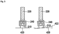
- the only possible movement of the brushes may be in a parallel direction out of the first plane such that both brushes move in a direction above the first plane at the same time or below the first plane at the same time as shown in figure 5 .
- first brush 310 and a second brush 320 may also apply to a single elongated brush which may have a first brush section 310 and a second brush section 320 opposing to the first brush section. Such a configuration is shown in Fig. 8 .
- the first brush 310 and the second brush 320 by their frictional forces 710, 720 induce a torque into the brush mount pivot when the slipring is rotating.
- the direction of rotation may be clockwise.
- the leading first brush 310 may be located further distant 712 from the brush mount pivot 223 in comparison to the distance 722 of the trailing second brush 320 to the brush mount pivot as shown in Figure 1 . Therefore a torque and an additional force component to each brush is generated.
- the leading first brush is additionally loaded with the force induced by the brush friction torque, the trailing brush is less loaded since the spring induced force is reduced by the brush friction momentum at this point. Due to the asymmetric position of the brush mount pivot 223 relative to the first brush 310 and the second brush 320, a higher force is applied to the second brush 320, compared to the first brush 310. This may compensate for the different forces generated by friction.
- the leading brush may be located further distant from the brush mount pivot than the trailing brush. This may be combined with all embodiments described herein.
- the brush mount pivot 223 may be arranged closer to the first brush 310 which then may be the trailing brush.
- the brush mount pivot 223 may be symmetrically between the first brush 310 and the second brush 320.
- FIG 2 a front view of the brush holder of Figure 1 is shown.
- the plane orthogonal to a brush mount pivot axis and/or to a slipring rotation axis 400 preferably is orthogonal to the drawing plane and further orthogonal to the rotation axis 130 of the slipring. It is preferred if blocking means are provided to prevent a rotation of the brush mount about an axis 225 within the plane orthogonal to a brush mount pivot axis and/or to a slipring rotation axis 420 and orthogonal to the rotation axis 130 of the slipring.
- Such blocking means may be overlapping areas of brush mount 240 and lever 220.
- the spring 230 may pulls and may generate a force into direction 232 which results in a force 228 on the brush mount 240, which is perpendicular to the sliding track.
- the distance between the brush mount pivot axis 224 and the first brush fixation means 241 is the same as the distance between the brush mount pivot axis 224 and the second brush fixation means 242, such that the forces to the brushes are the same if the brushes have the same lengths.
- the sliding track is circular and has a certain radius as shown in Figures 1 and 2 , for simplicity reasons in the following explanations, an infinite radius is assumed which may result in a plane, herein called the sliding track plane.
- the sliding track plane may also be used to linear sliding tracks which also be represented by the sliding track plane.
- the spring 230 is attached to the lever 220 outside the section of the lever between the base pivot 221 and the brush mount pivot 223.
- the spring may provide a pulling force.
- the lever may comprises a first lever section 226 which holds the brush mount 240 and a second lever section 227 to which the spring 230 is attached.
- the other side of the spring is attached to the base 210.
- the base pivot 221 is between the first lever section 226 and the second lever section 227.
- the angle between a second line between the spring attachment point and the base pivot axis 222 and a first line between the brush mount pivot axis 224 and the base pivot axis 222 is in a range between 80° and 120°. With such a configuration the direction of forces can be changed and the overall size may be reduced. With different lengths of the lever sections, the amount of force may also be modified. It is preferred, if the second lever section 227 is shorter than the first lever section 226.
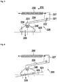
- this Figure a perfect configuration is shown where the sliding track plane 420 is a leveled configuration. Basically, this leveled configuration may be freely chosen as long as there is a main force component 228 perpendicular to the sliding track plane 420.
- FIG 4 an embodiment with a tilted plane is shown.
- the sliding track plane 420 is tilted as shown with reference number 421. This may easily be compensated by the brush mount which pivots about its first pivot axis accordingly, such that again both brushes are in contact with the plane. Accordingly, there is again a force 228 perpendicular to the tilted sliding track plane 421.
- FIG. 5 an embodiment with a slanted sliding track plane is shown.
- the sliding track plane 420 is in a slanted configuration as shown by reference number 422. This may occur if the rotation axis of the slipring is not precisely parallel to the base pivot axis.
- the brush would increase its contact surface to the sliding track, as the edge would be worn down.
- the slipring is not eccentrical or moving otherwise, there would be a continuous movement and the angle of the slanted plane may change continuously, which would not allow to provide a constant wear of the brush, a normal slipring brush would have sever changing contact properties.
- this may also be dynamically compensated, as the brush may easily follow the movements of the sliding track. It is preferred to have only the first and the second pivot axis at the brush mount. Preferably, other degrees of movement of the brush mount relative to the lever are not desired as they may lead to an instability and oscillations increasing brush wear.
- FIG 6 a side view of an embodiment of a brush holder 500 with an elastic lever 520 comprising wires is shown.
- the lever 520 comprises two parallel wires which are fixed together at their ends and which are parallel to a brush mount pivot axis and/or to a slipring rotation axis of a cylindrical slipring and/or parallel to a track surface of a disc shaped slipring. They may be injection molded or otherwise be fixedly held within the base 510.
- the wires may be one piece connected at the brush mount end. As the wires are connected together at both ends, they cannot twist and may only be bent in one plane (the plane orthogonal to a brush mount pivot axis and/or to a slipring rotation axis).
- the spring constant of the lever is designed such that it produces a desired force on the brushes.
- the brush mount is connected to the lever by a brush mount pivot 524, pivotable in a plane orthogonal to a brush mount pivot axis and/or to a slipring rotation axis as already described above. Therefore, this embodiment also has the same advantages as the embodiment above.
- the material of the spring may be spring, steel, or brass material. It is also preferred if the lever is able to conduct current which would simplify the electrical connection of the brushes. There may be spacers 529 at the wires for further stabilizing the wires.
- Figure 7 shows a perspective view of an embodiment with a wire lever. It further shows the brush mount 540 with first brush fixation means 541 and second brush fixation means 542. These brush fixation means may hold a brush or a sleeve for holding a brush.
- Figure 8 shows an embodiment with a metal foam brush 350.
- the base and the lever are basically the same a shown in figure 1 .
- a foam brush carrier 352 which may be a sheet of copper or any other conductive material.
- the foam brush carrier is connected to a litz wire which may be a wire as shown or a wire as shown in any of the other figures.
- the brush mount is also modified to hold the foam brush carrier and/or the foam brush.
- it preferably has a planar surface, which may be matched to at least one of the foam brush (with, length, radius) and/or the sliding track (width, radius).
- the foam brush carrier can be a part of the brush mount.
- a planar sliding track section is shown. It may be part of a linear sliding track or of a disc type planar slipring.
- asymmetric position of the pivot axis as described under Fig.1 is of advantage when a single brush is mounted with a contact area between brush and slipring extending to both sides of the brush mount pivot.
- a leading brush section may be located further distant from the brush mount pivot than a trailing brush section.
- the bottom side of the foam brush carrier may be bent to the radius of the sliding track.
- Figure 9 shows a section of an embodiment of the lever.
- a plurality of encapsulated hollow spaces 620 are contained between 3-D printed sidewalls 610.
- Figure 10 shows different forces at the brush holder and is further explained in detail in the section describing fig. 1 .
Landscapes
- Motor Or Generator Current Collectors (AREA)
Claims (14)
- Ein Bürstenhalter (200) umfasst eine Bürstenbefestigung (240), die von einem Hebel (220) an einer Basis (210) gehalten wird, wobei
der Hebel (220) durch einen Basisschwenkpunkt (221) schwenkbar mit der Basis (210) verbunden ist, wobei der Basisschwenkpunkt eine Basisschwenkachse (222) hat, und
eine Feder (230) zwischen der Basis (210) und dem Hebel (220) vorgesehen ist, wobei
der Hebel (220) in seiner Bewegung innerhalb einer ersten Ebene (400) orthogonal zur Basisschwenkachse (222) begrenzt ist,
die Bürstenbefestigung (240) mit dem Hebel (220) durch einen Bürstenbefestigungsschwenkpunkt (223) verbunden ist,
dadurch gekennzeichnet, dass
der Bürstenbefestigungsschwenkpunkt nur eine erste Schwenkachse parallel zur Basisschwenkachse (222) hat. - Bürstenhalter (200) nach Anspruch 1,
dadurch gekennzeichnet, dass
die Bürstenbefestigung (240) zumindest ein erstes Bürstenbefestigungsmittel (241) und ein zweites Bürstenbefestigungsmittel (242) umfasst, wobei der Bürstenbefestigungsschwenkpunkt (223) zwischen dem ersten Bürstenbefestigungsmittel (241) und dem zweiten Bürstenbefestigungsmittel (242) ist, und
der Abstand zwischen dem ersten Bürstenbefestigungsmittel (241) und dem Bürstenbefestigungsschwenkpunkt (223) größer ist als der Abstand zwischen dem zweiten Bürstenbefestigungsmittel (242) und dem Bürstenbefestigungsschwenkpunkt (223). - Bürstenhalter (200) nach Anspruch 2,
dadurch gekennzeichnet, dass
der Abstand zwischen dem ersten Bürstenbefestigungsmittel (241) und dem Bürstenbefestigungsschwenkpunkt (223) um mindestens 10%, vorzugsweise zwischen 20% und 50% größer ist als der Abstand zwischen dem zweiten Bürstenbefestigungsmittel (242) und dem Bürstenbefestigungsschwenkpunkt (223). - Bürstenhalter (200) nach einem der vorhergehenden Ansprüche,
dadurch gekennzeichnet, dass
die Bürstenbefestigung (240) frei schwenkbar um eine Achse parallel zur Basisschwenkachse innerhalb eines Winkels im Bereich von 30°, vorzugsweise 20° und am meisten bevorzugt 10° ist. - Bürstenhalter (200) nach einem der vorhergehenden Ansprüche,
dadurch gekennzeichnet, dass
der aktive Bürstenkontaktbereich auf einer ersten Seite des Bürstenbefestigungsschwenkpunkts (223) um mindestens 10%, vorzugsweise zwischen 20% und 50% größer ist als an einer zweiten Seite des Bürstenbefestigungsschwenkpunkts (223). - Bürstenhalter (200) nach einem der vorhergehenden Ansprüche,
dadurch gekennzeichnet, dass
der Hebel (220) eine Vielzahl von eingekapselten Hohlräumen (620) umfasst, um das Hebelgewicht zu reduzieren. - Bürstenhalter (200) nach einem der vorhergehenden Ansprüche,
dadurch gekennzeichnet, dass
der Hebel mindestens eines von einem Schaum, einer Netzstruktur, einer Wabenstruktur, einem Fachwerk oder einer Leichtbaukonstruktion mit Strukturen entlang der Kraftlinien oder eine ähnliche 3D-Druckstruktur umfasst. - Bürstenhalter (200) nach einem der vorhergehenden Ansprüche,
dadurch gekennzeichnet, dass
die Feder (230) eine Zugfeder und vorzugsweise eine Schraubenfeder ist und/oder die Feder (230) parallel zur Basis angeordnet ist und/oder die Feder länger als der Hebel (220) ist. - Bürstenhalter (200) nach einem der vorhergehenden Ansprüche,
dadurch gekennzeichnet, dass
der Hebel einen ersten Hebelabschnitt (226) umfasst, der die Bürstenbefestigung (240) hält, und einen zweiten Hebelabschnitt (227) umfasst, an dem die Feder (230) angebracht ist, wobei der Basisschwenkpunkt (221) zwischen dem ersten Hebelabschnitt (226) und dem zweiten Hebelabschnitt (227) liegt und
vorzugsweise der Winkel zwischen einer ersten Linie zwischen der Bürstenbefestigungsschwenkachse 224 und der Basisschwenkachse 222 und eine zweite Linie zwischen dem Federbefestigungspunkt und der Basisschwenkachse 222 in einem Bereich zwischen 80° und 120° liegt und vorzugsweise der zweite Hebelabschnitt (227) kürzer ist als der erste Hebelabschnitt (226), und
vorzugsweise ist der zweite Hebelabschnitt (227) kürzer als der erste Hebelabschnitt (226) ist, und
vorzugsweise der Hebel (220) ein fester Hebel sein kann. - Bürstenhalter (200) nach einem der vorhergehenden Ansprüche,
dadurch gekennzeichnet, dass
die Bürstenbefestigung (240) von der Feder (230) in eine Richtung weg von der Basis (210) gezogen wird und/oder
die Bürstenbefestigung (240) eine zweite Schwenkachse orthogonal zur ersten Schwenkachse hat. - Bürstenhalter (200) nach einem der vorhergehenden Ansprüche,
bei dem der Hebel (220) ein elastischer Hebel ist, welcher nur in einer Bewegungsebene (400) orthogonal zu einer Schleifring-Rotationsachse eines zylindrischen Schleifrings und/oder orthogonal zu einer Schleifbahnoberfläche eines scheibenförmigen Schleifrings biegsam ist,
und der Hebel (220) fest mit der Basis verbunden ist,
dadurch gekennzeichnet, dass
die Bürstenbefestigung (240) mit dem Hebel (220) durch einen in der Bewegungsebene (400) schwenkbaren Bürstenbefestigungsschwenkpunkt (223) verbunden ist. - Bürstenhalter (200) nach dem vorhergehenden Anspruch,
dadurch gekennzeichnet, dass
der Hebel (220) zwei parallele Drähte umfasst. - Bürstenhalter (200) nach einem der vorhergehenden Ansprüche,
dadurch gekennzeichnet, dass
ein Litzendraht (250) zwischen der Bürstenbefestigung (240) und der Basis (210) vorgesehen ist, der vorzugsweise innerhalb der Schraubenfeder (230) geführt ist, wenn eine Schraubenfeder vorgesehen ist. - Bürstenhalter (200) nach einem der vorhergehenden Ansprüche,
dadurch gekennzeichnet, dass
die Bürstenbefestigung (240) mindestens eine Gleitbürste hält, die mindestens eines aus einem gesinterten Kohlenstoffmaterial, einem Metallschaum oder einem Drahtbündel umfasst.
Priority Applications (1)
| Application Number | Priority Date | Filing Date | Title |
|---|---|---|---|
| EP20162519.1A EP3683903B1 (de) | 2018-08-07 | 2019-08-06 | Halter für schleifringbürsten |
Applications Claiming Priority (2)
| Application Number | Priority Date | Filing Date | Title |
|---|---|---|---|
| EP18187738.2A EP3609027A1 (de) | 2018-08-07 | 2018-08-07 | Halter für schleifringbürsten |
| PCT/EP2019/071120 WO2020030639A1 (en) | 2018-08-07 | 2019-08-06 | Holder for slip ring brushes |
Related Child Applications (2)
| Application Number | Title | Priority Date | Filing Date |
|---|---|---|---|
| EP20162519.1A Division-Into EP3683903B1 (de) | 2018-08-07 | 2019-08-06 | Halter für schleifringbürsten |
| EP20162519.1A Division EP3683903B1 (de) | 2018-08-07 | 2019-08-06 | Halter für schleifringbürsten |
Publications (2)
| Publication Number | Publication Date |
|---|---|
| EP3659219A1 EP3659219A1 (de) | 2020-06-03 |
| EP3659219B1 true EP3659219B1 (de) | 2020-10-21 |
Family
ID=63168341
Family Applications (3)
| Application Number | Title | Priority Date | Filing Date |
|---|---|---|---|
| EP18187738.2A Withdrawn EP3609027A1 (de) | 2018-08-07 | 2018-08-07 | Halter für schleifringbürsten |
| EP20162519.1A Active EP3683903B1 (de) | 2018-08-07 | 2019-08-06 | Halter für schleifringbürsten |
| EP19746108.0A Active EP3659219B1 (de) | 2018-08-07 | 2019-08-06 | Halter für schleifringbürsten |
Family Applications Before (2)
| Application Number | Title | Priority Date | Filing Date |
|---|---|---|---|
| EP18187738.2A Withdrawn EP3609027A1 (de) | 2018-08-07 | 2018-08-07 | Halter für schleifringbürsten |
| EP20162519.1A Active EP3683903B1 (de) | 2018-08-07 | 2019-08-06 | Halter für schleifringbürsten |
Country Status (4)
| Country | Link |
|---|---|
| US (1) | US11171457B2 (de) |
| EP (3) | EP3609027A1 (de) |
| CN (1) | CN112602240B (de) |
| WO (1) | WO2020030639A1 (de) |
Family Cites Families (20)
| Publication number | Priority date | Publication date | Assignee | Title |
|---|---|---|---|---|
| US423309A (en) * | 1890-03-11 | Berlain | ||
| US349999A (en) * | 1886-09-28 | George jeffery | ||
| US717656A (en) * | 1902-04-26 | 1903-01-06 | Walter W Beeler | Brush-holder. |
| US747890A (en) * | 1903-03-05 | 1903-12-22 | Cons Car Heating Co | Brush-holder for electrical machines. |
| GB191215471A (en) * | 1912-07-02 | 1913-02-13 | Pintsch S Electric Mfg Company | Improvements in Brush Holders for Dynamo Electric Machines. |
| GB146828A (en) | 1915-10-18 | 1921-07-14 | Entz Motor Patents Corp | Improvements in and relating to brush holders for electrical devices |
| GB191515471A (en) | 1915-11-02 | 1916-09-28 | Harry W Cox And Company Ltd | An Improved Apparatus for Adjustably Holding X-ray Tubes. |
| FR530801A (fr) | 1921-02-08 | 1921-12-31 | Perfectionnements aux porte-charbons dans les machines électriques | |
| GB290002A (en) * | 1927-03-12 | 1928-05-10 | Stone J & Co Ltd | Improvements in brushes and brush holders for dynamoelectric machines |
| DE717781C (de) * | 1940-03-11 | 1942-02-23 | Schunk & Ebe | Buerstenhalter fuer elektrische Maschinen |
| US2520379A (en) * | 1947-04-28 | 1950-08-29 | Superior Carbon Products Inc | Brush support |
| DE967293C (de) | 1951-04-27 | 1957-10-31 | Siemens Ag | Buerste fuer elektrische Maschinen |
| DE7100971U (de) | 1971-01-13 | 1971-04-29 | Heid & Co Gmbh Kg | Schleifringburstenhalter |
| US4350909A (en) * | 1980-03-17 | 1982-09-21 | Mitsuba Electric Mfg. Co., Ltd. | Brush lead structure for motor-immersed fuel pumps |
| US4359656A (en) * | 1980-11-07 | 1982-11-16 | Robert Bosch Gmbh | Voltage regulator for generators |
| RO92696B1 (ro) * | 1985-11-30 | 1987-10-01 | îNTREPRINDEREA "1 MAI" | Sistem mobil de asigurare contact perie-inel |
| US20050029896A1 (en) | 2003-07-11 | 2005-02-10 | Jan Stewart | Brush holder assembly |
| US10128725B2 (en) * | 2011-08-16 | 2018-11-13 | Ab Dynamoborstfabriken | Contact brush holder |
| CN105470766B (zh) | 2015-12-30 | 2019-01-08 | 国营成都无线电专用设备厂 | 一种汇流环自动对中减振电刷组件 |
| EP3364508A1 (de) * | 2017-02-15 | 2018-08-22 | Schleifring GmbH | Halter für schleifringbürsten |
-
2018
- 2018-08-07 EP EP18187738.2A patent/EP3609027A1/de not_active Withdrawn
-
2019
- 2019-08-06 EP EP20162519.1A patent/EP3683903B1/de active Active
- 2019-08-06 WO PCT/EP2019/071120 patent/WO2020030639A1/en not_active Ceased
- 2019-08-06 CN CN201980052331.0A patent/CN112602240B/zh active Active
- 2019-08-06 EP EP19746108.0A patent/EP3659219B1/de active Active
-
2021
- 2021-02-02 US US17/165,411 patent/US11171457B2/en active Active
Non-Patent Citations (1)
| Title |
|---|
| None * |
Also Published As
| Publication number | Publication date |
|---|---|
| WO2020030639A1 (en) | 2020-02-13 |
| EP3659219A1 (de) | 2020-06-03 |
| US20210159652A1 (en) | 2021-05-27 |
| EP3683903B1 (de) | 2021-10-27 |
| US11171457B2 (en) | 2021-11-09 |
| CN112602240A (zh) | 2021-04-02 |
| EP3609027A1 (de) | 2020-02-12 |
| CN112602240B (zh) | 2022-03-15 |
| EP3683903A1 (de) | 2020-07-22 |
Similar Documents
| Publication | Publication Date | Title |
|---|---|---|
| CN101147309B (zh) | 大直径电滑环的电接触技术和制造方法 | |
| US10181668B2 (en) | Spring contacts and related methods | |
| JP5241180B2 (ja) | 先端に繊維を備えて接触させる技術を組入れた小型スリップ・リング | |
| US12300950B2 (en) | Internally sprung shunt | |
| US7719158B2 (en) | Slip-ring brush and slip-ring unit equipped with such a slip-ring brush | |
| EP0743720A2 (de) | Bürstenanordnung für einen elektrischen Motor | |
| EP2745359B1 (de) | Schleifbürstenhalter und verfahren zur vorspannung einer schleifbürste | |
| KR900003400Y1 (ko) | 브러시 장치를 구비한 소형 회전기 | |
| WO2013171106A1 (en) | Idc contact element for an electrical plug | |
| US6794984B2 (en) | Sliding-type electric component having carbon fiber contact | |
| US11171457B2 (en) | Holder for slip ring brushes | |
| CN102162510B (zh) | 致动器 | |
| EP3364508A1 (de) | Halter für schleifringbürsten | |
| JP2003169450A (ja) | ブラシ装置及びブラシ付きモータ | |
| CN220508996U (zh) | 一种轴绝缘监测装置 | |
| US10833467B2 (en) | Vibration absorbing device for slip-ring brushes | |
| CN113328313A (zh) | 集电器与分拣装置 | |
| CN103042930B (zh) | 集电装置 | |
| JP2001313139A (ja) | 集電機構 | |
| CN213877711U (zh) | 一种基于微型丝杆传动机构的小直径多圈线绕电位器 | |
| EP0599572B1 (de) | Elektrodynamische Maschine mit Blechbügelbürsten | |
| CN222679916U (zh) | 线材导通总成、放线机构及焊线机 | |
| CN110518752B (zh) | 马达 | |
| US3543068A (en) | Commutator brush assembly | |
| JPH0684572A (ja) | スリップリング |
Legal Events
| Date | Code | Title | Description |
|---|---|---|---|
| STAA | Information on the status of an ep patent application or granted ep patent |
Free format text: STATUS: UNKNOWN |
|
| STAA | Information on the status of an ep patent application or granted ep patent |
Free format text: STATUS: THE INTERNATIONAL PUBLICATION HAS BEEN MADE |
|
| PUAI | Public reference made under article 153(3) epc to a published international application that has entered the european phase |
Free format text: ORIGINAL CODE: 0009012 |
|
| STAA | Information on the status of an ep patent application or granted ep patent |
Free format text: STATUS: REQUEST FOR EXAMINATION WAS MADE |
|
| 17P | Request for examination filed |
Effective date: 20190812 |
|
| AK | Designated contracting states |
Kind code of ref document: A1 Designated state(s): AL AT BE BG CH CY CZ DE DK EE ES FI FR GB GR HR HU IE IS IT LI LT LU LV MC MK MT NL NO PL PT RO RS SE SI SK SM TR |
|
| AX | Request for extension of the european patent |
Extension state: BA ME |
|
| GRAP | Despatch of communication of intention to grant a patent |
Free format text: ORIGINAL CODE: EPIDOSNIGR1 |
|
| STAA | Information on the status of an ep patent application or granted ep patent |
Free format text: STATUS: GRANT OF PATENT IS INTENDED |
|
| DAV | Request for validation of the european patent (deleted) | ||
| DAX | Request for extension of the european patent (deleted) | ||
| INTG | Intention to grant announced |
Effective date: 20200706 |
|
| GRAS | Grant fee paid |
Free format text: ORIGINAL CODE: EPIDOSNIGR3 |
|
| GRAA | (expected) grant |
Free format text: ORIGINAL CODE: 0009210 |
|
| STAA | Information on the status of an ep patent application or granted ep patent |
Free format text: STATUS: THE PATENT HAS BEEN GRANTED |
|
| AK | Designated contracting states |
Kind code of ref document: B1 Designated state(s): AL AT BE BG CH CY CZ DE DK EE ES FI FR GB GR HR HU IE IS IT LI LT LU LV MC MK MT NL NO PL PT RO RS SE SI SK SM TR |
|
| REG | Reference to a national code |
Ref country code: GB Ref legal event code: FG4D |
|
| REG | Reference to a national code |
Ref country code: CH Ref legal event code: EP |
|
| REG | Reference to a national code |
Ref country code: DE Ref legal event code: R096 Ref document number: 602019001036 Country of ref document: DE |
|
| REG | Reference to a national code |
Ref country code: IE Ref legal event code: FG4D |
|
| REG | Reference to a national code |
Ref country code: AT Ref legal event code: REF Ref document number: 1326808 Country of ref document: AT Kind code of ref document: T Effective date: 20201115 |
|
| REG | Reference to a national code |
Ref country code: AT Ref legal event code: MK05 Ref document number: 1326808 Country of ref document: AT Kind code of ref document: T Effective date: 20201021 |
|
| REG | Reference to a national code |
Ref country code: NL Ref legal event code: MP Effective date: 20201021 |
|
| PG25 | Lapsed in a contracting state [announced via postgrant information from national office to epo] |
Ref country code: NO Free format text: LAPSE BECAUSE OF FAILURE TO SUBMIT A TRANSLATION OF THE DESCRIPTION OR TO PAY THE FEE WITHIN THE PRESCRIBED TIME-LIMIT Effective date: 20210121 Ref country code: GR Free format text: LAPSE BECAUSE OF FAILURE TO SUBMIT A TRANSLATION OF THE DESCRIPTION OR TO PAY THE FEE WITHIN THE PRESCRIBED TIME-LIMIT Effective date: 20210122 Ref country code: FI Free format text: LAPSE BECAUSE OF FAILURE TO SUBMIT A TRANSLATION OF THE DESCRIPTION OR TO PAY THE FEE WITHIN THE PRESCRIBED TIME-LIMIT Effective date: 20201021 Ref country code: RS Free format text: LAPSE BECAUSE OF FAILURE TO SUBMIT A TRANSLATION OF THE DESCRIPTION OR TO PAY THE FEE WITHIN THE PRESCRIBED TIME-LIMIT Effective date: 20201021 Ref country code: PT Free format text: LAPSE BECAUSE OF FAILURE TO SUBMIT A TRANSLATION OF THE DESCRIPTION OR TO PAY THE FEE WITHIN THE PRESCRIBED TIME-LIMIT Effective date: 20210222 |
|
| REG | Reference to a national code |
Ref country code: LT Ref legal event code: MG4D |
|
| PG25 | Lapsed in a contracting state [announced via postgrant information from national office to epo] |
Ref country code: PL Free format text: LAPSE BECAUSE OF FAILURE TO SUBMIT A TRANSLATION OF THE DESCRIPTION OR TO PAY THE FEE WITHIN THE PRESCRIBED TIME-LIMIT Effective date: 20201021 Ref country code: IS Free format text: LAPSE BECAUSE OF FAILURE TO SUBMIT A TRANSLATION OF THE DESCRIPTION OR TO PAY THE FEE WITHIN THE PRESCRIBED TIME-LIMIT Effective date: 20210221 Ref country code: LV Free format text: LAPSE BECAUSE OF FAILURE TO SUBMIT A TRANSLATION OF THE DESCRIPTION OR TO PAY THE FEE WITHIN THE PRESCRIBED TIME-LIMIT Effective date: 20201021 Ref country code: SE Free format text: LAPSE BECAUSE OF FAILURE TO SUBMIT A TRANSLATION OF THE DESCRIPTION OR TO PAY THE FEE WITHIN THE PRESCRIBED TIME-LIMIT Effective date: 20201021 Ref country code: BG Free format text: LAPSE BECAUSE OF FAILURE TO SUBMIT A TRANSLATION OF THE DESCRIPTION OR TO PAY THE FEE WITHIN THE PRESCRIBED TIME-LIMIT Effective date: 20210121 Ref country code: AT Free format text: LAPSE BECAUSE OF FAILURE TO SUBMIT A TRANSLATION OF THE DESCRIPTION OR TO PAY THE FEE WITHIN THE PRESCRIBED TIME-LIMIT Effective date: 20201021 Ref country code: ES Free format text: LAPSE BECAUSE OF FAILURE TO SUBMIT A TRANSLATION OF THE DESCRIPTION OR TO PAY THE FEE WITHIN THE PRESCRIBED TIME-LIMIT Effective date: 20201021 |
|
| PG25 | Lapsed in a contracting state [announced via postgrant information from national office to epo] |
Ref country code: HR Free format text: LAPSE BECAUSE OF FAILURE TO SUBMIT A TRANSLATION OF THE DESCRIPTION OR TO PAY THE FEE WITHIN THE PRESCRIBED TIME-LIMIT Effective date: 20201021 Ref country code: NL Free format text: LAPSE BECAUSE OF FAILURE TO SUBMIT A TRANSLATION OF THE DESCRIPTION OR TO PAY THE FEE WITHIN THE PRESCRIBED TIME-LIMIT Effective date: 20201021 |
|
| REG | Reference to a national code |
Ref country code: DE Ref legal event code: R097 Ref document number: 602019001036 Country of ref document: DE |
|
| PG25 | Lapsed in a contracting state [announced via postgrant information from national office to epo] |
Ref country code: LT Free format text: LAPSE BECAUSE OF FAILURE TO SUBMIT A TRANSLATION OF THE DESCRIPTION OR TO PAY THE FEE WITHIN THE PRESCRIBED TIME-LIMIT Effective date: 20201021 Ref country code: RO Free format text: LAPSE BECAUSE OF FAILURE TO SUBMIT A TRANSLATION OF THE DESCRIPTION OR TO PAY THE FEE WITHIN THE PRESCRIBED TIME-LIMIT Effective date: 20201021 Ref country code: CZ Free format text: LAPSE BECAUSE OF FAILURE TO SUBMIT A TRANSLATION OF THE DESCRIPTION OR TO PAY THE FEE WITHIN THE PRESCRIBED TIME-LIMIT Effective date: 20201021 Ref country code: EE Free format text: LAPSE BECAUSE OF FAILURE TO SUBMIT A TRANSLATION OF THE DESCRIPTION OR TO PAY THE FEE WITHIN THE PRESCRIBED TIME-LIMIT Effective date: 20201021 Ref country code: SK Free format text: LAPSE BECAUSE OF FAILURE TO SUBMIT A TRANSLATION OF THE DESCRIPTION OR TO PAY THE FEE WITHIN THE PRESCRIBED TIME-LIMIT Effective date: 20201021 Ref country code: SM Free format text: LAPSE BECAUSE OF FAILURE TO SUBMIT A TRANSLATION OF THE DESCRIPTION OR TO PAY THE FEE WITHIN THE PRESCRIBED TIME-LIMIT Effective date: 20201021 |
|
| PLBE | No opposition filed within time limit |
Free format text: ORIGINAL CODE: 0009261 |
|
| STAA | Information on the status of an ep patent application or granted ep patent |
Free format text: STATUS: NO OPPOSITION FILED WITHIN TIME LIMIT |
|
| PG25 | Lapsed in a contracting state [announced via postgrant information from national office to epo] |
Ref country code: DK Free format text: LAPSE BECAUSE OF FAILURE TO SUBMIT A TRANSLATION OF THE DESCRIPTION OR TO PAY THE FEE WITHIN THE PRESCRIBED TIME-LIMIT Effective date: 20201021 |
|
| 26N | No opposition filed |
Effective date: 20210722 |
|
| PG25 | Lapsed in a contracting state [announced via postgrant information from national office to epo] |
Ref country code: IT Free format text: LAPSE BECAUSE OF FAILURE TO SUBMIT A TRANSLATION OF THE DESCRIPTION OR TO PAY THE FEE WITHIN THE PRESCRIBED TIME-LIMIT Effective date: 20201021 Ref country code: AL Free format text: LAPSE BECAUSE OF FAILURE TO SUBMIT A TRANSLATION OF THE DESCRIPTION OR TO PAY THE FEE WITHIN THE PRESCRIBED TIME-LIMIT Effective date: 20201021 |
|
| PG25 | Lapsed in a contracting state [announced via postgrant information from national office to epo] |
Ref country code: SI Free format text: LAPSE BECAUSE OF FAILURE TO SUBMIT A TRANSLATION OF THE DESCRIPTION OR TO PAY THE FEE WITHIN THE PRESCRIBED TIME-LIMIT Effective date: 20201021 |
|
| PG25 | Lapsed in a contracting state [announced via postgrant information from national office to epo] |
Ref country code: MC Free format text: LAPSE BECAUSE OF FAILURE TO SUBMIT A TRANSLATION OF THE DESCRIPTION OR TO PAY THE FEE WITHIN THE PRESCRIBED TIME-LIMIT Effective date: 20201021 |
|
| REG | Reference to a national code |
Ref country code: BE Ref legal event code: MM Effective date: 20210831 |
|
| PG25 | Lapsed in a contracting state [announced via postgrant information from national office to epo] |
Ref country code: IS Free format text: LAPSE BECAUSE OF FAILURE TO SUBMIT A TRANSLATION OF THE DESCRIPTION OR TO PAY THE FEE WITHIN THE PRESCRIBED TIME-LIMIT Effective date: 20210221 Ref country code: LU Free format text: LAPSE BECAUSE OF NON-PAYMENT OF DUE FEES Effective date: 20210806 |
|
| PG25 | Lapsed in a contracting state [announced via postgrant information from national office to epo] |
Ref country code: IE Free format text: LAPSE BECAUSE OF NON-PAYMENT OF DUE FEES Effective date: 20210806 Ref country code: BE Free format text: LAPSE BECAUSE OF NON-PAYMENT OF DUE FEES Effective date: 20210831 |
|
| REG | Reference to a national code |
Ref country code: CH Ref legal event code: PL |
|
| PG25 | Lapsed in a contracting state [announced via postgrant information from national office to epo] |
Ref country code: LI Free format text: LAPSE BECAUSE OF NON-PAYMENT OF DUE FEES Effective date: 20220831 Ref country code: CH Free format text: LAPSE BECAUSE OF NON-PAYMENT OF DUE FEES Effective date: 20220831 |
|
| PG25 | Lapsed in a contracting state [announced via postgrant information from national office to epo] |
Ref country code: CY Free format text: LAPSE BECAUSE OF FAILURE TO SUBMIT A TRANSLATION OF THE DESCRIPTION OR TO PAY THE FEE WITHIN THE PRESCRIBED TIME-LIMIT Effective date: 20201021 |
|
| PG25 | Lapsed in a contracting state [announced via postgrant information from national office to epo] |
Ref country code: HU Free format text: LAPSE BECAUSE OF FAILURE TO SUBMIT A TRANSLATION OF THE DESCRIPTION OR TO PAY THE FEE WITHIN THE PRESCRIBED TIME-LIMIT; INVALID AB INITIO Effective date: 20190806 |
|
| PG25 | Lapsed in a contracting state [announced via postgrant information from national office to epo] |
Ref country code: MK Free format text: LAPSE BECAUSE OF FAILURE TO SUBMIT A TRANSLATION OF THE DESCRIPTION OR TO PAY THE FEE WITHIN THE PRESCRIBED TIME-LIMIT Effective date: 20201021 |
|
| PG25 | Lapsed in a contracting state [announced via postgrant information from national office to epo] |
Ref country code: MT Free format text: LAPSE BECAUSE OF FAILURE TO SUBMIT A TRANSLATION OF THE DESCRIPTION OR TO PAY THE FEE WITHIN THE PRESCRIBED TIME-LIMIT Effective date: 20201021 |
|
| PGFP | Annual fee paid to national office [announced via postgrant information from national office to epo] |
Ref country code: DE Payment date: 20250819 Year of fee payment: 7 |
|
| PGFP | Annual fee paid to national office [announced via postgrant information from national office to epo] |
Ref country code: GB Payment date: 20250822 Year of fee payment: 7 |
|
| PGFP | Annual fee paid to national office [announced via postgrant information from national office to epo] |
Ref country code: FR Payment date: 20250821 Year of fee payment: 7 |
|
| PG25 | Lapsed in a contracting state [announced via postgrant information from national office to epo] |
Ref country code: TR Free format text: LAPSE BECAUSE OF FAILURE TO SUBMIT A TRANSLATION OF THE DESCRIPTION OR TO PAY THE FEE WITHIN THE PRESCRIBED TIME-LIMIT Effective date: 20201021 |