EP3659244B1 - Procédé et dispositif d'enroulement d'une natte d'enroulement ondulé ainsi que natte d'enroulement ondulé ainsi fabriquée - Google Patents
Procédé et dispositif d'enroulement d'une natte d'enroulement ondulé ainsi que natte d'enroulement ondulé ainsi fabriquée Download PDFInfo
- Publication number
- EP3659244B1 EP3659244B1 EP18759244.9A EP18759244A EP3659244B1 EP 3659244 B1 EP3659244 B1 EP 3659244B1 EP 18759244 A EP18759244 A EP 18759244A EP 3659244 B1 EP3659244 B1 EP 3659244B1
- Authority
- EP
- European Patent Office
- Prior art keywords
- winding
- jaw
- mat
- wire
- wave
- Prior art date
- Legal status (The legal status is an assumption and is not a legal conclusion. Google has not performed a legal analysis and makes no representation as to the accuracy of the status listed.)
- Active
Links
Images


Classifications
-
- H—ELECTRICITY
- H02—GENERATION; CONVERSION OR DISTRIBUTION OF ELECTRIC POWER
- H02K—DYNAMO-ELECTRIC MACHINES
- H02K15/00—Processes or apparatus specially adapted for manufacturing, assembling, maintaining or repairing of dynamo-electric machines
- H02K15/04—Processes or apparatus specially adapted for manufacturing, assembling, maintaining or repairing of dynamo-electric machines of windings prior to their mounting into the machines
- H02K15/043—Processes or apparatus specially adapted for manufacturing, assembling, maintaining or repairing of dynamo-electric machines of windings prior to their mounting into the machines winding flat conductive wires or sheets
- H02K15/0432—Distributed windings
- H02K15/0433—Distributed windings of the wave winding type
-
- H—ELECTRICITY
- H02—GENERATION; CONVERSION OR DISTRIBUTION OF ELECTRIC POWER
- H02K—DYNAMO-ELECTRIC MACHINES
- H02K15/00—Processes or apparatus specially adapted for manufacturing, assembling, maintaining or repairing of dynamo-electric machines
- H02K15/04—Processes or apparatus specially adapted for manufacturing, assembling, maintaining or repairing of dynamo-electric machines of windings prior to their mounting into the machines
-
- H—ELECTRICITY
- H02—GENERATION; CONVERSION OR DISTRIBUTION OF ELECTRIC POWER
- H02K—DYNAMO-ELECTRIC MACHINES
- H02K3/00—Details of windings
- H02K3/04—Windings characterised by the conductor shape, form or construction, e.g. with bar conductors
Definitions
- the invention relates to a wave winding method for winding a wave winding mat to form a coil winding of an electrical machine.
- the invention also relates to a wave winding device for winding a wave winding mat to form a coil winding of an electrical machine.
- the present invention is in the field of the production of electric motors or other electrical machines, such as, for example, generators, which are designed for high performance, reliable operation and high efficiency.
- electric motors are to be produced which can be used as traction motors for electric vehicles or hybrid vehicles and have, for example, a nominal power between 20 kW and 400 kW. It is For the construction of stators of such powerful electrical machines, it is advantageous to provide the highest possible coil density.
- wave winding mats which can be inserted into radially open grooves of a holding body, such as in particular the main body of a stator or a rotor.
- the coil windings are made in particular from wires with a rectangular cross-section, for which winding methods designed for winding wires with a round cross-section are not very suitable. Therefore, according to references [1] to [11], wave winding mats for providing the coil windings are proposed which have, for example, a plurality of parallel wires which have straight wire sections which are arranged in the slots of a stator. These straight sections alternate between an inner radial position and an outer radial position in the component of the electrical machine, with bends being provided between these straight wire sections on the longitudinal edges of the corrugated winding mat, which are referred to as winding heads.
- the references [2] to [4] propose the winding of a bundle of parallel wires on a winding blade that can rotate about an axis of rotation.
- the bundle of parallel wires is bent in sections into inclined wire sections which extend between the straight wire sections and, after being bent over on the winding blade, form the winding heads.
- [1] describes the winding of a wave mat with a winding device that does not have a winding blade.
- a bending takes place on a bending edge provided on a bending element, which is rotatable about an axis of rotation.
- the invention has set itself the task of providing a wave mat and a method and a device for producing such a mat, by means of which the production process of an electrical machine can be simplified.
- the invention creates a wave winding method with the steps of claim 1 and a wave winding device with the features of claim 5.
- the invention provides a wave winding method for winding a wave winding mat for forming a coil winding of an electrical machine, comprising winding one or more wires with a predefined wire spacing between wire sections, the wire spacing being set differently for different areas of the wave winding mat.
- wire spacings can be done in different ways.
- the wires are held on jaws which are preferably designed to hold the wires at a predetermined distance.
- At least one first jaw is exchanged on a holding device for holding wires that are guided essentially in parallel.
- At least one first jaw is exchanged on a holding device for holding essentially parallel wires and at least one second jaw on a rotatable winding device.
- an offset between two wire sections connected by an inclined wire section is changed in order to form different wire spacings.
- winding heads which are preferably formed with wire sections bent in a U-shape, are shaped differently in different areas of the winding shaft mat.
- the invention provides a wave winding method for winding a wave winding mat for forming a coil winding of an electrical machine, characterized by winding one or more wires with a predefined wire spacing between wire sections, winding heads being shaped differently in different areas of the wave winding mat.
- the wave winding method comprises the step: Transporting an already wound area of the wave winding mat to be produced by means of several jaws by moving the jaws on a jaw guide extending in the direction of an axis of rotation of a winding device.
- the wave winding method comprises the step: Return of jaws from the end of the jaw guide to its beginning.
- a wave winding mat for forming a coil winding of an electrical machine wherein essentially straight wire sections are arranged at a predefined wire spacing from one another, the Wave wrap mat has areas in which the pre-defined wire spacing is different.
- Such a wave winding mat can be produced by a wave winding method according to one of the preceding embodiments and / or by means of a wave winding device according to one of the embodiments explained below.
- a first area with a first wire spacing d1 extends from one end of the wave winding mat in the longitudinal direction of the wave winding mat, that a third area with a third wire distance d3 extends in the longitudinal direction of the wave winding mat to the other end, that between the first Area and the third area a second area is provided with a second wire spacing d2 and that the following applies: d1 ⁇ d2 ⁇ d3.
- winding heads which are preferably formed with wire sections bent in a U-shape, are shaped differently in different areas of the winding shaft mat.
- a wave winding mat for forming a coil winding of an electrical machine wherein essentially straight wire sections are arranged at a predefined wire spacing from one another, the wave winding mat having areas in which the shape of winding heads is different.
- the winding heads are formed on a first region, which extends from one end of the winding shaft mat in the longitudinal direction of the winding shaft mat, to one side in a first direction transverse to the longitudinal direction, and in a third region, which extends from the other end of the winding shaft mat extends in the longitudinal direction, the end windings are shaped more to the other side in the second direction opposite to the first direction transversely to the longitudinal direction.
- the winding heads can extend more radially outward, and on an inner layer formed by the third region, the winding heads can extend more inward. This further facilitates the installation of the wave mat.
- the invention provides a wave winding device for winding a wave winding mat for forming a coil winding of an electrical machine, comprising: at least one holding device for holding substantially parallel wires, on which a first jaw is provided for contact with the wires, a winding device rotatable about an axis of rotation and having at least one bending edge, on which a second jaw for contact with the wires for the purpose of holding the wires is provided when bending around the bending edge, and a jaw exchange arrangement for exchanging the first and / or the second jaw.
- the wave winding device is designed in such a way that at least one first jaw is exchanged on the holding device and / or at least one second jaw is exchanged on the rotatable winding device in order to form different wire gaps.
- the wave winding device is preferably provided for carrying out the wave winding method according to one of the preceding embodiments.
- the winding device has a bending bar or winding bar which can rotate about the axis of rotation and on which the at least one bending edge, preferably a first bending edge and a second bending edge, is provided.
- any bending edge can be used to a large extent in order to bend the corrugated mat using jaws, e.g. two second jaws, together with the bending edge around the bending edge.
- the bending edge can rotate like a winding sword, similar to how it is described in the literature reference [1]. The bending edge can be pulled away when a certain degree of bending is reached, and the remaining bending can then be achieved by pressing together.
- one of the second jaws is arranged upstream of the bending edge in the wire feed direction so that the wires do not "go away" downwards, i.e. the force exerted by the bending edge on the wires is supported.
- the other second jaw preferably presses the wire against the bending edge.
- An offset for forming inclined wire sections is preferably bent by means of the first jaws of the holding device, while bending takes place by means of the second jaws of a bending device.
- the second jaws are preferably guided on the bending device.
- the winding device has a jaw guide for guiding a plurality of second jaws on a jaw guide path running with at least one directional component in the direction of the axis of rotation.
- the jaw exchange arrangement has a jaw feed device for feeding second jaws into the jaw guide and / or a jaw return device for returning second jaws from one end of the jaw guide to a beginning of the jaw guide.
- a winding head forming device for forming the winding heads Wave winding mat is provided while retaining the same on at least one second jaw.
- the winding head shaping device preferably has a plurality of areas provided with different shapes or stamps for the different shaping of winding heads on different areas of the corrugated winding mat.
- the respective jaw exchange unit of the jaw exchange arrangement can each have at least one magazine for exchanging the jaws.
- rotary magazines or linear magazines can be used.
- the jaw exchange arrangement has a rotating magazine on the holding device for exchanging first jaws.
- a linear magazine is provided.
- a combination of rotating magazine and linear magazine can also be used.
- first and / or second jaws have wire receptacles for the lateral positioning of the essentially parallel-guided wires.
- first and / or second jaws are provided with different distances between their wire receptacles and can be exchanged by the jaw exchange arrangement.
- a plurality of holding devices are provided, of which at least one can be moved, preferably driven, relative to at least one other and / or to the winding device in a direction transverse to the axis of rotation and / or in a direction parallel to the axis of rotation.
- At least one fixed holding device and at least one movable holding device are provided.
- a movement stroke of a movable holding device is adjustable.
- Preferred embodiments of the invention deal with the production of a winding mat for stators and rotors of an electric motor or another electric machine, such as a generator.
- a preferred embodiment of the changing mat has a large number of interwoven wires or consists of such wires.
- Such winding mats are used to form coil windings on a component of the electrical machine such as, in particular, the stator or rotor.
- the winding mat is wound onto a joining tool after winding or inserted directly into the component, such as a stator.
- grooves for receiving wire sections are provided on the component, for example.
- the diameter of the inner layer of the changing mat is smaller than the diameter of the outer rolled up layer of the changing mat.
- the groove spacing inwards becomes smaller.
- a preferred embodiment of the invention relates to a method and a device for producing a wire mat with different wire spacings. This has advantages, among other things, when it is wound onto a joining tool or when it is inserted directly into a component of an electrical machine such as the stator of an electric motor.
- a preferred embodiment of the invention relates to a method and a device for winding different wire spacings. This is preferably made possible by using interchangeable jaws and / or rotating jaws.
- a device with rotating jaws is preferably proposed. Circulating jaws are preferably used to shape the changing mat.
- a preferred embodiment of the winding mat is used to be wound several times around the circumference of a stator. This results in different radii for the different layers. This results in problems when inserting into the individual grooves. Therefore, a preferred embodiment of the mat is divided into three different sections, each of which has different wire spacings.
- the mat itself has two layers, each with bends on the side, the so-called winding heads.
- the distances between the wires are preferably only very small, e.g. in the range of a few millimeters.
- the differences between the wire spacing are e.g. between 0.01 mm and 0.5 mm.
- the number of areas with different wire spacings depends, for example, on the number of layers to be produced with them. If the changing mat is only to be laid in two layers on the component, two areas with different wire spacing would be suitable, for example. If four layers are to be provided, four areas of different wire spacing would be advantageous.
- the invention relates to the use of a wave mat, obtainable by a method or with a device according to one of the preceding embodiments in the production of a component of an electrical machine, in particular a stator or rotor of an electric motor or a generator, more in particular a traction motor of an electric vehicle .
- the invention relates to a method for producing a component of an electrical machine, in particular a rotor or stator of an electric motor, more in particular an electric drive motor of an electric or hybrid vehicle, comprising performing the wave winding method according to one of the preceding embodiments and inserting the wave winding mat in a Holding body of the component, so as to form coil windings of the component.
- the invention relates to a device for producing a component of an electric machine, in particular a rotor or stator of an electric motor, more in particular a drive electric motor of an electric or hybrid vehicle, comprising a wave winding device according to one of the preceding embodiments and an insertion device for inserting the wave winding mat in a holding body of the component.
- the insertion device preferably has an insertion tool onto which the wave winding mat can be placed, e.g. wound up, prior to insertion.
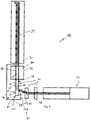
- Figs. 1 and 2 show a stator 10 of an electric motor that can be used as a traction motor for electric vehicles as an example of a component of an electric machine provided with a coil winding 12.
- the stator 10 has a base body as a holding body 14 and a coil winding 12 held thereon.
- the holding body 14 is annular and has a series of radially open grooves 16 into which several layers of straight wire sections 18 of the coil winding 12 are inserted.
- the grooves 16 are open towards the inside.
- the coil winding 12 is formed by inserting a wave winding mat 20, which is closer to the Fig. 3 and 4th is shown.
- the corrugated winding mat 20 is formed from a bundle 24 of parallel wires 24, the straight wire sections 18 being arranged with a predetermined wire spacing d1, d2, d3.
- the wires 24 run alternately in a first wire layer 26 and a second wire layer 28 of the wave winding mat 20, with winding heads 34 formed by inclined wire sections 30 having a bend 32 being provided on the two longitudinal edges of the wave winding mat 20.
- the wave winding mat 20 shown has a first area 36 which, after being inserted into the holding body 14, forms an outer layer of the coil winding 12, a second area 40 which, after being inserted into the holding body 14, forms a middle layer 42 of the coil winding 12, and a third area 44 which, after being inserted into the holding body 14, forms an inner layer 46 of the coil winding 12.
- the grooves 16 have a greater distance from one another on the outside than on the inside due to their radial alignment.
- the straight wire sections 18 are spaced further apart from one another in the outer layer 38 than in the inner layer 46.
- the wire spacing d1 in the first area 36 which forms the outer layer 38 in the exemplary embodiment shown here, is greater than the wire spacing d2 in the second area 40, which forms the middle layer 42.
- the wire spacing d2 of the second area 40 is in turn greater than the wire spacing d3 of the third area 44, which forms the inner layer 46.
- the wire spacings d1, d2, d3 are selected in accordance with the wire spacings of the coil windings 12 inserted into the slots 16, as shown in FIG Fig. 2 are specified.
- FIG. 3 and 4th a wave winding mat 20 for forming a coil winding 12 of an electrical machine, wherein essentially straight wire sections 18 are arranged at a predefined wire spacing d1, d2, d3 from one another, the wave winding mat 20 having areas 36, 40, 44 in which the predefined wire spacing d1, d2, d3 is different before being inserted into a component of the electrical machine.
- the winding heads 34 are also shaped differently in the different areas 36, 40, 44.
- the winding heads 34 are shaped more towards that side of the wave winding mat 20 transversely to their longitudinal direction, which in use on the Stator 10 is directed outwards.
- the winding heads 34 in the third area 44 are directed more towards the opposite side, which are shaped inwards when used as intended as a coil winding 12.
- the winding heads 34 of the second area 40 have the same extension on both sides. This also means that the shape of the wave winding mat 20 is better adapted to the later shape of the coil winding 12.
- the wave winding mat 20 can be inserted more easily into the grooves 16, so that overall the manufacture of the stator 10 is facilitated.
- the two measures of the differently defined wire spacing d1, d2, d3 and the differently shaped winding heads 34 are provided together in the preferred embodiment. In other configurations, only one of these measures is provided.
- the coil winding 12 is formed in that the wave winding mat 20 is wound in three layers 38, 42, 46 and inserted into the slots 16. Accordingly, in the embodiment shown, three areas 36, 40, 44 with different wire spacings d1, d2, d3 are provided. In other configurations, the coil winding 12 consists of two layers of a wave winding mat 20, the wave winding mat 20 then also being able to have only two areas with different wire spacing. In other configurations, four or five layers are provided, in which case more areas with different wire spacing can be provided accordingly.
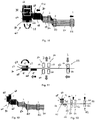
- Fig. 5 shows an overview of the wave winding device 50.
- the wave winding device 50 is used to wind the wave winding mat 20, which is suitable for forming the coil winding 12 for the electrical machine.
- the wave winding device 50 has at least one holding device 52, 54, 56 and a winding device 60 which is rotatable about an axis of rotation 58 and has at least one bending edge 62, 64.
- At least one first jaw 66 is provided on the at least one holding device 52, 54, 56 for releasably holding the wires 24 on the holding device 52, 54, 56.
- At least one second jaw 68 for releasably holding the wires 24 in the area of the bending edge 62, 64 is provided on the winding device 60.
- a jaw exchange arrangement 70 is provided for exchanging the at least one first jaw 66 and the at least one second jaw 68.
- the jaw exchange assembly 70 has one or more first jaw exchange units 84 for exchanging first jaws 66 and one or more second jaw exchange units for exchanging second jaws 68.
- a wire supply device 72 for providing the bundle of parallel wires 24 and a winding head forming device 74 and an output unit 76 for transferring the wound wave winding mat 20 to a workpiece carrier are also provided.
- the wire supply device 72 has bearings, not shown in greater detail here, for wire reels, from which the individual wires 24 can be unrolled and guided parallel to the at least one holding device 52.
- not only one holding device 52 but a plurality of holding devices 52, 54, 56 is provided, by means of which transport steps and bending steps can be carried out on the wires 24 before the winding heads are bent.
- a first holding device 52 is provided, which is designed to feed the wire.
- the first holding device 52 is the first machine axis in a feed direction for the wire (to the left and right in FIG Fig. 5 ) movable back and forth.
- a second holding device 54 is also provided, which itself is designed to be fixed or stationary within the shaft winding device 50. This second holding device 54 thus forms a second machine axis.
- a third holding device 56 is also provided, which can be moved back and forth as a third machine axis in a direction transverse to the feed direction - in the direction of the width of the wire bundle or the axis of rotation 58 - in order to bend an offset for the inclined wire sections 30.
- the third holding device 56 is in relation to the second holding device 54 in FIG Fig. 5 movable up and down.
- All of the aforementioned holding devices 52, 54, 56 can be moved up and down together in order to follow the movement of the at least one bending edge 62, 64.
- Each of the holding devices 52, 54, 56 has a plurality of first jaws 66.
- Each holding device 52, 54 has pairs of associated first jaws 66 that can be moved relative to one another.
- the Fig. 6 and 7th show an exemplary structure for each of the holding devices 52, 54, 56.
- a first jaw carrier 78 and a second jaw carrier 80 are provided, which are attached to jaw carrier guides 82, as indicated by arrows in FIG Fig. 6 shown, are movable towards one another to clamp the wires 24 between them between a corresponding pair of first jaws 66 or are movable away from one another to give the wires 24 free.
- first jaws 66-1, 66-2, 66-3 are provided in pairs, which are designed to define different wire spacings d1, d2, d3.
- first jaws 66-1 are provided for the first wire spacing d1, a pair of first jaws 66-2 for the second wire spacing d2 and a pair of first jaws 66-3 for the third wire spacing d3.
- the jaw exchange arrangement 70 has a first jaw exchange unit 84 for exchanging the respective pair of first jaws 66 on the respective holding device 52, 54, 56.
- the jaw exchange unit 84 for exchanging the first jaws 66 is designed as a rotary magazine 86.
- the jaws on the second jaw carrier 80 have fixed receiving grooves 88 on their clamping surface as wire receptacles 87, the spacing of which corresponds to the desired wire spacing d1, d2, d3.
- the jaws on the first jaw carrier 78 have a flexible profile on their clamping surface with flexible receiving grooves 90 as wire receptacles 87, the spacing of which also corresponds to the respective desired wire spacing d1, d2, d3, but the position of the receiving grooves 90 is flexible. This is implemented, for example, by spring elements 92 which can flexibly evade. A flexible clamping force can be exerted on the wires 24 by the spring elements 92.
- the first jaws 66 are arranged, for example, on a rotary module and are automatically changed depending on the wire spacing d1, d2, d3. In the illustrated embodiments, there are two rotary modules, each with three Baking provided. This means that three different wire spacings can be wound.
- the contour of the first jaws 66-1, 66-2, 66-3 determines the wire spacing. Each wire 24 is reliably clamped with the jaw on the second jaw carrier 80 and the opposite jaw on the first jaw carrier 78 with a flexible profile.
- the second holding device 54 and the third holding device 56 are essentially constructed in the same way as the first holding device 52 is anchored only in the height movable holding device carrier (not shown).
- the jaw carrier guide 82 of the first holding device 52 is arranged on a carriage or the like, not shown in detail, which can be moved back and forth in the wire feed direction and which, for example, is movably mounted on the holding device carrier.
- the jaw carrier guide 82 of the third holding device 56 is movable transversely thereto, for example also arranged on a slide, not shown in detail, which can also be moved on the holding device carrier.
- the winding device 60 in the exemplary embodiment shown in more detail here has a winding blade 94 which can be rotated about the axis of rotation 58.
- This is designed like a strip with conically tapering ends, so that a first bending edge 62 and an opposing second bending edge 64 are formed on each of the narrow sides.
- the winding device 60 also has a plurality of second jaws 68.
- the second jaws 68 are listed as rotating jaws. They can be guided on a circular path 96 from the end of the winding device 60 to the beginning thereof.
- Jaw guides 98 are provided within the winding device 60, on which the circumferential second jaws 68 are first guided to the respective side of the winding blade 94 in order to grasp the wires 94 and then along the winding blade 94 in the direction transverse to Feed direction (up in Fig. 5 ), ie in particular in the direction of the axis of rotation 58.
- the jaw guide 98 and the orbit 96 form second jaw exchange units of the jaw exchange arrangement 70.
- Several different second jaws 68 are provided, each of which has wire receptacles 87 with fixed receiving grooves 88, as described above with regard to the first jaws 66-1, 66-2, 66- 3 of the second jaw carrier 80 have been explained.
- the different second jaws 68 have receiving grooves 88 spaced apart from one another as wire receivers 87 in accordance with the wire spacings d1, d2, d3 to be handled.
- the circular path 96 forms a jaw return device 100 for returning second jaws 68 from one end of the jaw guide 98 to the beginning of the jaw guide 98 second jaws with the correct distances between the wire receptacles 87 at the beginning of the jaw guide 98 are fed.
- a jaw feed device 102 is also provided for feeding correspondingly matching second jaws 68 into the jaw guide 98.
- the second jaws 68 have a clamping surface on a block or body, by means of which they are suitable for form-fitting guidance on the jaw guide 98, which is designed as a rail, for example.
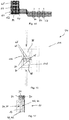
- the jaw guide 98 extends in the direction of the axis of rotation 58 beyond the winding blade 94 into the winding head forming device 74, which is closer to the Fig. 15 and 16 is shown.
- the winding head forming device 74 has a forming unit 104 with one or more forming punches 106 and a counter holder 108.
- a first forming dies 106-1 for forming the winding heads 34 on the first region 36
- a second forming dies 106-2 for forming the winding heads 34 on the second region 40
- a third Forming punches 106-3 are provided for forming the winding heads 34 on the third region 44.
- the forming punches 106-1, 106-2, 106-3 each have different shape geometries.
- the rotary modules on all holding devices 52, 54, 56 are initially set on the first jaws 66-1 for the first wire spacing d1 at the beginning of the production of a wave winding mat 20.
- the jaw carriers 78, 80 of the second holding device 54 and the third holding device 56 are moved towards one another so that the wires 24 are clamped between the first jaws 66 of the second holding device 54 and the third holding device 56, the wires 24 in the wire receptacles 87 with the wire spacing d1.
- the jaw carriers 78, 80 of the first holding device 52 are moved away from one another.
- the first holding device 52 is moved in the direction of the wire supply device 72.
- the third holding device 56 is moved in the direction parallel to the axis of rotation 58.
- the first jaws 66 of the second holding device 54 and the first jaws 66 of the third holding device 56 thus clamp the wire 24.
- the first jaws 66 of the first holding device 52 are open.
- the movement of the second holding device 54 and the third holding device 56 to each other produce the offset 110.
- the rotating second jaws 68 are pushed onto the winding blade 94, the respective second jaws 68 with the wire holder spacing set to the first wire spacing d1 87 are used.
- the circumferential second jaws 68 are pushed further in the jaw guides 98 accordingly.
- the first holding device 52 is moved towards the winding bar 94 in synchronism with the tension that is established on the wire 24 by the winding bar 94.
- the jaw feed device 102 moves the newly provided second jaw 68 towards the winding blade 94.
- the newly provided second jaw 68 is moved from the position in front of the winding bar 94 to the position below the winding bar 94.
- This second jaw 68 guides the wires 24 and serves as a counter bearing during bending.
- the axis of rotation 58 of the winding blade 94 is stationary.
- the holding devices 52, 54, 56 are therefore fastened on a common holding device carrier which can be moved up and down and is not shown in detail and which ensures that the supplied wires 24 follow the movement of the bending edges 62, 64. This is in the Figures 12 and 13 shown.
- the windings of the first area 36 are first wound.
- the first jaws 66 on the holding devices 52, 54, 56 are then exchanged by the jaw exchange arrangement 70.
- the jaw exchange arrangement 70 by rotating the rotary magazines 36-1, 36-2 a change to the first jaw 66-2 for the second wire spacing d2.
- different second jaws 68 are then fed by the jaw feed device 102 and made available at the position in front of the winding blade 94.
- the movement path of the third holding device 56 is adapted. The transition from the second region 40 to the third region 44 takes place in the same way.
- the corresponding already wound areas of the wave mat 20 are guided by the rotating second jaws 68, which are guided in the jaw guides 98, in the direction of the axis of rotation 58 first continued on the winding blade 94 and so into the Fig. 15 and 16
- the mold unit 104 shown is transferred.
- the corrugated winding mat 20 is continued into the circumferential second jaw 68.
- the second jaws 68 which are correspondingly opposite one another, are now pressed onto one another.
- the winding head 34 is formed with the counter holder 108 and the forming die or dies 106.
- the wires 24 are held at the defined wire spacing d1, d2, d3 by the second jaws 68, and twisting of the wire 24 during forming is prevented.
- the winding head 34 is formed, it is pressed flat by the forming die 106.
- the winding head 34 can be shaped somewhat outwards or inwards by a different punch geometry. For this purpose, different form punches 106-1, 106-2, 106-3 according to Fig. 16 intended.
- the in Fig. 3 Produce the wave mat 20 shown.
- the wave winding mat 20 is used to be wound around the circumference of a stator 10 several times. This results in different radii for the different layers 38, 42, 46. So far, this has resulted in problems when inserting into the individual grooves.
- the corrugated winding mat 20 is therefore divided into three different sections - areas 36, 40, 44 - which each have different wire spacings d1, d2, d3.
- the wave winding mat 20 itself has two wire layers 27, 28, each with bends on the side - winding heads 34. The distances between the wires are only very small, they are in the lower millimeter range.
- An exemplary structure of the winding machine - shaft winding device 50 - is as follows: First there is a wire unwinding. Then a wire feed takes place. For this purpose, there is a device 52 acting as the first machine axis, which can move in the wire feed direction and thereby takes the wires 24 with it via retaining jaws.
- a further device 56 which acts as a second machine axis and which can move transversely thereto in order to bend an offset 110 of the wires 24 with respect to one another.
- the winding takes place, for example around a winding blade 94, which can rotate about an axis of rotation 58 transversely to the wire feed direction in order to carry out the windings.
- a winding blade 94 which can rotate about an axis of rotation 58 transversely to the wire feed direction in order to carry out the windings.
- In the area of the winding blade 94 there is a path running transversely to the feed axis on which different second jaws 68 can be placed.
- These second jaws 68 are supplied with corresponding wire grooves.
- corresponding grooves with corresponding wire spacings are supplied. In this way, the wires 24 lying next to one another are grasped and bent over by rotating the winding device 60.
- That holding device 56 which effects the lateral displacement, the wire package is then pushed to the side. The
- a forming unit 104 is then provided, which is used to form the winding heads 34.
- the winding heads 34 are also shaped with the aid of the second jaws 68. These thus predetermine the defined wire spacing.
- the defined wire spacing results from the securing of the second jaws 68 during the bending over by means of the winding device 60.
- the bending over results in the correct wire spacing in each case.
- Each of the three holding devices 52, 54, 56 has a jaw exchange unit 84, by means of which first jaws 66 with different wire spacing grooves can be used.
- the other jaw is inserted accordingly; in addition, the offset of the third holding device 56, which performs the lateral bending, is changed.
- the forming unit 104 is a pressing unit which, when the winding device 60 is at a standstill, moves together and presses the winding heads 34.
- the completely wound wave mat 20 provided with shaped winding heads 34 comes out, which can then be inserted into the stator 10 in a suitable manner.
- the different units and devices of the shaft winding device 50 can be electric motors, such as, for example, servomotors. Pneumatic and hydraulic drives are also possible.
Landscapes
- Engineering & Computer Science (AREA)
- Power Engineering (AREA)
- Manufacturing & Machinery (AREA)
- Manufacture Of Motors, Generators (AREA)
Claims (14)
- Procédé d'enroulement ondulé l'enroulement d'une natte d'enroulement ondulé (20) pour former un bobinage (12) d'une machine électrique, comprenant l'enroulement d'un ou plusieurs fils (24) avec un espacement de fil prédéfini (d1, d2, d3) entre les sections de fil (18, 30), caractérisé en ce
que l'espacement de fil (d1, d2, d3) est réglé différemment pour différentes zones de la natte d'enroulement ondulé (20), dans lequel, afin de former différents distances de fils (d1, d2, d3), un échange d'au moins une première mâchoire (66) sur un dispositif de maintien (52, 54, 56) pour maintenir des fils guidés sensiblement parallèles (24) et/ou un échange d'au moins une seconde mâchoire (68) sur un dispositif d'enroulement rotatif (60) a lieu. - Procédé d'enroulement ondulé selon la revendication 1,
caractérisé en ce
qu'un décalage entre deux sections de fil (18, 30) reliées par une section de fil inclinée (30) est modifié pour former différentes distances de fil (d1, d2, d3). - Procédé d'enroulement ondulé selon l'une quelconque des revendications précédentes, caractérisé par le transport d'une partie déjà enroulée (36, 40, 44) de la natte d'enroulement ondulé (20) à produire au moyen d'une pluralité de mâchoires (68) en déplaçant les mâchoires (68) sur un guide de mâchoires (82) s'étendant dans la direction d'un axe de rotation (58) d'un dispositif d'enroulement.
- Procédé d'enroulement ondulé selon la revendication 3,
caractérisé par le retour des mâchoires (68) de l'extrémité du guide des mâchoires (82) au début de celui-ci. - Procédé d'enroulement ondulé (50) pour enrouler une natte d'enroulement ondulé (20) selon le procédé d'enroulement de la revendication 1 pour former un enroulement de bobine (12) d'une machine électrique, comprenant:au moins un dispositif de maintien (52, 54, 56) pour maintenir des fils guidés sensiblement parallèles (24), sur lequel une première mâchoire (66) est prévue pour le contact avec les fils (24),un enrouleur (60) pouvant tourner autour de l'axe de rotation (58) et ayant au moins un bord de pliage (62, 64), l'enrouleur (60) ayant une seconde mâchoire (68) pour entrer en contact avec les fils (24) afin de maintenir les fils (24) lorsqu'ils sont pliés autour du bord de pliage (62, 64), caractérisé par un agencement d'échange de mâchoires (70) pour échanger la première et/ou la deuxième mâchoire (66, 68), le dispositif d'enroulement ondulé (50) étant conçu de telle sorte que, pour former différents écartements de fils (d1, d2, d3), un échange d'au moins une première mâchoire (66) a lieu sur le dispositif de maintien (52, 54, 56) et/ou un échange d'au moins une deuxième mâchoire (68) a lieu sur l'enrouleur rotatif (60).
- Dispositif d'enroulement ondulé (50) selon la revendication 5, caractérisé en ce que le dispositif d'enroulement ondulé (50) est conçu pour enrouler la natte d'enroulement ondulé (20) de telle sorte que des sections de fil (18) essentiellement droites sont disposées les unes par rapport aux autres à une distance de fil prédéfinie (d1, d2, d3) de telle sorte que la natte d'enroulement ondulé (20) présente des zones (36, 40, 44) dans lesquelles la distance de fil prédéfinie (d1, d2, d3) est différente.
- Dispositif d'enroulement ondulé (50) selon la revendication 6, caractérisé en ce que le dispositif d'enroulement ondulé (50) est conçu pour enrouler la natte d'enroulement (20) de telle sorte qu'une première zone (36) de la natte d'enroulement (20) avec un premier distance de fil d1 s'étende à partir d'une extrémité de la natte d'enroulement ondulé (20) dans l'extension longitudinale de la natte d'enroulement ondulé (20), en ce qu'une troisième zone (44) avec une troisième distance entre les fils d3 s'étend dans la direction d'extension longitudinale de la natte d'enroulement ondulé (20) jusqu'à l'autre extrémité, en ce qu'une deuxième zone (40) avec une deuxième distance entre les fils d2 est prévue entre la première zone (36) et la troisième zone (44), et en ce que il s'applique: d<d2<d3.
- Dispositif d'enroulement ondulé selon l'une quelconque des revendications 5 à 7, caractérisé en ce
que le dispositif d'enroulement (60) comprend un guide de mâchoires (98) pour guider une pluralité de secondes mâchoires (68) sur un chemin de guidage de mâchoires s'étendant avec au moins une composante directionnelle dans la direction de l'axe de rotation (58). - Dispositif d'enroulement ondulé (50) selon la revendication 8, caractérisé en ce que l'agencement d'échange de mâchoires (70) comprend un moyen d'alimentation en mâchoires (102) pour alimenter des secondes mâchoires (68) dans le guide de mâchoires (98) et/ou un moyen de retour de mâchoires (100) pour ramener des secondes mâchoires (68) d'une extrémité du guide de mâchoires (98) à un début du guide de mâchoires (98).
- Dispositif d'enroulement ondulé (50) selon la revendication 8 ou 9,
caractérisé en ce
qu'en outre, dans la zone du guide de mâchoire (98), un dispositif de formation de tête d'enroulement (74) est prévu pour former des têtes d'enroulement de la natte d'enroulement ondulé (20) en maintenant celui-ci sur au moins une deuxième mâchoire (68). - Dispositif d'enroulement ondulé (50) selon l'une quelconque des revendications 5 à 10,
caractérisé en ce
que l'agencement d'échange de mâchoires (70) comprend un magasin rotatif (86) sur le dispositif de maintien pour remplacer les premières mâchoires (66). - Dispositif d'enroulement ondulé (50) selon l'une quelconque des revendications 5 à 11, caractérisé en ce
que les premières et/ou secondes mâchoires (66, 68) comprennent des réceptacles de fil (87) pour positionner latéralement les fils guidés sensiblement parallèles (24). - Dispositif d'enroulement ondulé (50) selon la revendication 12, caractérisé en ce
que différentes premières et/ou secondes mâchoires (66, 68) sont pourvues de différentes distances entre leurs réceptacles de fil (87) et sont échangeables par l'agencement d'échange de mâchoires (70). - Dispositif d'enroulement ondulé (50) selon l'une quelconque des revendications 5 à 13,caractérisé en ceque plusieurs dispositifs de maintien (52, 54, 56) sont prévus, dont au moins un est mobile par rapport à au moins un autre et/ou au dispositif d'enroulement (60) dans une direction transversale à l'axe de rotation (58) et/ou dans une direction parallèle à l'axe de rotation (58), de préférence de manière entraînée, et/ouen ce qu'au moins un dispositif de maintien fixe (52, 54, 56) et au moins un dispositif de maintien mobile (52, 54, 56) sont prévus et/ou en ce qu'une course de déplacement d'un dispositif de maintien mobile (52, 54, 56) est réglable.
Applications Claiming Priority (3)
| Application Number | Priority Date | Filing Date | Title |
|---|---|---|---|
| DE102017117191 | 2017-07-28 | ||
| DE102017120559.4A DE102017120559A1 (de) | 2017-07-28 | 2017-09-06 | Verfahren und Vorrichtung zum Wickeln einer Wellenwickelmatte sowie damit herstellbare Wellenwickelmatte |
| PCT/DE2018/100670 WO2019020148A1 (fr) | 2017-07-28 | 2018-07-27 | Procédé et dispositif d'enroulement d'une natte d'enroulement ondulé ainsi que natte d'enroulement ondulé ainsi fabriquée |
Publications (2)
| Publication Number | Publication Date |
|---|---|
| EP3659244A1 EP3659244A1 (fr) | 2020-06-03 |
| EP3659244B1 true EP3659244B1 (fr) | 2021-10-20 |
Family
ID=65004192
Family Applications (1)
| Application Number | Title | Priority Date | Filing Date |
|---|---|---|---|
| EP18759244.9A Active EP3659244B1 (fr) | 2017-07-28 | 2018-07-27 | Procédé et dispositif d'enroulement d'une natte d'enroulement ondulé ainsi que natte d'enroulement ondulé ainsi fabriquée |
Country Status (5)
| Country | Link |
|---|---|
| US (1) | US11581789B2 (fr) |
| EP (1) | EP3659244B1 (fr) |
| CN (1) | CN111149285B (fr) |
| DE (1) | DE102017120559A1 (fr) |
| WO (1) | WO2019020148A1 (fr) |
Cited By (2)
| Publication number | Priority date | Publication date | Assignee | Title |
|---|---|---|---|---|
| DE102022117040A1 (de) | 2022-05-17 | 2023-11-23 | Schaeffler Technologies AG & Co. KG | Verfahren und Vorrichtung zum Herstellen einer Wellenwicklung mit variablem Drahtabstand |
| WO2023222153A1 (fr) | 2022-05-17 | 2023-11-23 | Schaeffler Technologies AG & Co. KG | Procédé et dispositif de production d'un enroulement ondulé à espacement de fil variable |
Families Citing this family (18)
| Publication number | Priority date | Publication date | Assignee | Title |
|---|---|---|---|---|
| WO2020177815A1 (fr) | 2019-03-05 | 2020-09-10 | Grob-Werke Gmbh & Co. Kg | Procédé de cintrage, procédé de fabrication, dispositif de cintrage et dispositif de fabrication pour un tapis d'enroulement ondulé ainsi que tapis d'enroulement ondulé obtenu avec ce procédé |
| DE102019106711A1 (de) | 2019-03-15 | 2020-09-17 | Grob-Werke Gmbh & Co. Kg | Verfahren und Vorrichtung zum mehrlagigen Einfügen einer Spulenmatte in ein Bauteil einer elektrischen Maschine |
| EP3731379B1 (fr) * | 2019-04-23 | 2021-11-10 | Marsilli S.p.A. | Stator pour moteurs électriques et procédé de fourniture d'un tel stator |
| DE102019208227A1 (de) * | 2019-06-05 | 2020-12-10 | Volkswagen Aktiengesellschaft | Verfahren zur Herstellung einer Statorwicklung und Elektromaschine |
| DE102020105600A1 (de) | 2020-03-03 | 2021-09-09 | Schaeffler Technologies AG & Co. KG | Stator für eine elektrische Maschine |
| EP3886303B1 (fr) | 2020-03-23 | 2023-03-08 | Grob-Werke GmbH & Co. KG | Procédé et dispositifs de réception, de serrage ou d'insertion de mat de bobines pour un composant d'une machine électrique |
| DE102020110428A1 (de) | 2020-04-16 | 2021-10-21 | Schaeffler Technologies AG & Co. KG | Doppel-Zweischicht-Wellenwicklung |
| DE102020118925A1 (de) * | 2020-07-17 | 2022-01-20 | Schaeffler Technologies AG & Co. KG | Verfahren zur Herstellung einer Spulenwicklung und Wickelschablone |
| EP4226480A1 (fr) * | 2020-10-07 | 2023-08-16 | Schaeffler Technologies AG & Co. KG | Stator pour machine tournante électrique, procédé de fabrication du stator et machine tournante électrique |
| DE102021134599A1 (de) | 2020-12-23 | 2022-02-17 | Grob-Werke Gmbh & Co. Kg | Verfahren, Vorrichtung und Anordnung zum Einbringen einer Wicklung in Statornuten mittels Zentrifugalkraft |
| DE102021115862A1 (de) | 2021-06-18 | 2022-12-22 | Grob-Werke Gmbh & Co. Kg | Halteeinrichtung zum Ausrichten von Wellenwicklungsdrähten, Fügevorrichtung und Fügeverfahren |
| DE102022101153A1 (de) | 2022-01-19 | 2023-07-20 | Schaeffler Technologies AG & Co. KG | Verfahren für das Wickeln von windungsspezifischen Drahtlängen und Rotor oder Stator mit einer Spulenwicklung mit windungsspezifischen Drahtlängen |
| SE545790C2 (en) * | 2022-05-17 | 2024-02-06 | Scania Cv Ab | An interweaving machine and a method for producing a winding for an electric machine |
| DE102022118256A1 (de) | 2022-07-21 | 2024-02-01 | Aumann Espelkamp Gmbh | Verfahren und Vorrichtung zum Herstellen einer Mehrdraht-Biegung einer Wellenwicklung für eine Spulenwicklung einer elektrischen Maschine |
| DE102022120095A1 (de) * | 2022-08-10 | 2024-02-15 | Schaeffler Technologies AG & Co. KG | Führungsbacke |
| DE102023112382A1 (de) * | 2023-05-11 | 2024-11-14 | Schaeffler Technologies AG & Co. KG | Verfahren zur Herstellung eines Drahtpakets zur Verwendung in einer Wellenwicklungsmatte, Drahtpaket zur Verwendung in einer Wellenwicklungsmatte sowie Vorrichtung zur Herstellung eines aus wenigstens einem ersten bügelförmig gebogenen Drahtrohling und wenigsten einem zweiten bügelförmig gebogenen Drahtrohling gebildeten Drahtpakets |
| CN120108847A (zh) * | 2023-12-04 | 2025-06-06 | 本田技研工业株式会社 | 导体成形装置及导体成形方法 |
| DE102024123231A1 (de) * | 2024-08-14 | 2026-02-19 | Schaeffler Technologies AG & Co. KG | Vorrichtung und Verfahren zum Wickeln von Wellenwicklungen, Formbacke und Formzange |
Family Cites Families (25)
| Publication number | Priority date | Publication date | Assignee | Title |
|---|---|---|---|---|
| FR2086758A5 (fr) * | 1970-04-08 | 1971-12-31 | Henry Baudot Jacques | |
| US5289129A (en) * | 1992-10-13 | 1994-02-22 | The Trustees Of The University Of Pennsylvania | Multiple winding MRI gradient coil |
| DE19900922C1 (de) * | 1999-01-13 | 2000-09-21 | Elmotec Elektro Motoren Tech | Verfahren und Vorrichtung zur Herstellung einer Wellenwicklung für Statoren oder Rotoren elektrischer Maschinen |
| AU2003203324A1 (en) * | 2002-02-09 | 2003-09-04 | Wei Huang | A switching pattern ac induction motor |
| JP2003324911A (ja) * | 2002-04-30 | 2003-11-14 | Toyota Motor Corp | コイルセグメントの環状配列装置およびコイルセグメントの環状配列方法 |
| DE10328955B4 (de) * | 2003-06-27 | 2008-07-24 | Elmotec Statomat Vertriebs Gmbh | Verfahren und Vorrichtung zum Formen von Wellenwicklungen für Rotor- und Statorblechpakete elektrischer Maschinen |
| DE10328956A1 (de) | 2003-06-27 | 2005-01-20 | Elmotec Statomat Vertriebs Gmbh | Verfahren und Vorrichtung zum Einführen von Wellenwicklungen in Rotor- und Statorblechpakete elektrischer Maschinen |
| WO2005074105A1 (fr) * | 2004-01-28 | 2005-08-11 | Mitsubishi Denki Kabushiki Kaisha | Procede pour la production d'un assemblage d'enrulement d'une machine dynamo-electrique et systeme d eproduction d'un assemblage d'enroulement |
| DE102004035084A1 (de) * | 2004-07-20 | 2006-02-16 | Elmotec Statomat Vertriebs Gmbh | Verfahren und Vorrichtung zur Herstellung einer Spulenwicklung für Statoren oder Rotoren elektrischer Maschinen sowie damit herzustellender Stator oder Rotor |
| DE102004042768A1 (de) * | 2004-09-03 | 2006-03-09 | Ina - Drives & Mechatronics Gmbh & Co. Ohg | Hochpoliger, linearer oder rotativer Synchron-Direktantriebsmotor |
| FR2896351B1 (fr) * | 2006-01-16 | 2008-04-18 | Valeo Equip Electr Moteur | Procede pour realiser un stator de machine electrique tournante et agencement de conducteurs sur un support |
| DE102008019479A1 (de) * | 2008-04-17 | 2009-10-29 | Elmotec Statomat Vertriebs Gmbh | Stator oder Rotor für elektrische Maschinen und Verfahren zu seiner Herstellung |
| US8487729B2 (en) * | 2009-02-02 | 2013-07-16 | Northrop Grumman Guidance & Electronics | Magnetic solenoid for generating a substantially uniform magnetic field |
| GB2483889A (en) * | 2010-09-22 | 2012-03-28 | Tesla Engineering Ltd | Gradient coil sub assemblies |
| US10110078B2 (en) * | 2013-08-23 | 2018-10-23 | Borgwarner Inc. | Distributed cascaded winding for electric machines |
| JP6291839B2 (ja) * | 2013-12-26 | 2018-03-14 | アイシン精機株式会社 | 3相回転電機の波巻き巻線 |
| KR102619070B1 (ko) * | 2015-04-30 | 2023-12-27 | 어탑 에스.피.에이. | 물결형의 직조 코일 어셈블리를 형성하기 위한 방법 및 장치 |
| DE102015120661A1 (de) | 2015-11-27 | 2017-06-01 | Elmotec Statomat Vertriebs Gmbh | Verfahren zur Herstellung einer Spulenwicklung zum Einlegen in radial offene Nuten von Statoren oder Rotoren von Elektromaschinen |
| DE102015120963A1 (de) | 2015-12-02 | 2017-06-08 | Elmotec Statomat Vertriebs Gmbh | Verfahren und Vorrichtung zur Herstellung von Rotoren oder Spulen von elektrischen Maschinen |
| NO3182568T3 (fr) | 2015-12-18 | 2018-05-05 | ||
| DE102016118871A1 (de) | 2016-10-05 | 2018-04-05 | Elmotec Statomat Holding GmbH | Spulenwicklung für Statoren oder Rotoren |
| DE102016222818A1 (de) * | 2016-11-18 | 2018-05-24 | Volkswagen Aktiengesellschaft | Wellenwicklungsspule für ein Statorblechpaket einer elektrischen Maschine |
| CN111373635B (zh) * | 2017-12-14 | 2022-07-12 | 株式会社爱信 | 定子 |
| ES2790251T3 (es) * | 2018-01-11 | 2020-10-27 | Aumann Espelkamp Gmbh | Dispositivo de bobinado ondulado y procedimiento para fabricar un bobinado ondulado |
| JP2021058076A (ja) * | 2019-04-24 | 2021-04-08 | 本田技研工業株式会社 | 導体成形装置及び波巻コイルの製造方法 |
-
2017
- 2017-09-06 DE DE102017120559.4A patent/DE102017120559A1/de not_active Withdrawn
-
2018
- 2018-07-27 WO PCT/DE2018/100670 patent/WO2019020148A1/fr not_active Ceased
- 2018-07-27 EP EP18759244.9A patent/EP3659244B1/fr active Active
- 2018-07-27 US US16/634,001 patent/US11581789B2/en active Active
- 2018-07-27 CN CN201880063444.6A patent/CN111149285B/zh active Active
Non-Patent Citations (1)
| Title |
|---|
| None * |
Cited By (3)
| Publication number | Priority date | Publication date | Assignee | Title |
|---|---|---|---|---|
| DE102022117040A1 (de) | 2022-05-17 | 2023-11-23 | Schaeffler Technologies AG & Co. KG | Verfahren und Vorrichtung zum Herstellen einer Wellenwicklung mit variablem Drahtabstand |
| WO2023222153A1 (fr) | 2022-05-17 | 2023-11-23 | Schaeffler Technologies AG & Co. KG | Procédé et dispositif de production d'un enroulement ondulé à espacement de fil variable |
| DE102022117040B4 (de) * | 2022-05-17 | 2025-10-30 | Schaeffler Technologies AG & Co. KG | Verfahren und Vorrichtung zum Herstellen einer Wellenwicklung mit variablem Drahtabstand |
Also Published As
| Publication number | Publication date |
|---|---|
| US11581789B2 (en) | 2023-02-14 |
| EP3659244A1 (fr) | 2020-06-03 |
| CN111149285A (zh) | 2020-05-12 |
| US20200395831A1 (en) | 2020-12-17 |
| WO2019020148A1 (fr) | 2019-01-31 |
| CN111149285B (zh) | 2022-05-03 |
| DE102017120559A1 (de) | 2019-01-31 |
Similar Documents
| Publication | Publication Date | Title |
|---|---|---|
| EP3659244B1 (fr) | Procédé et dispositif d'enroulement d'une natte d'enroulement ondulé ainsi que natte d'enroulement ondulé ainsi fabriquée | |
| EP3381108B1 (fr) | Procédé de fabrication d'un enroulement de bobine à déposer dans des gorges radialement ouvertes de stators et de rotors de machines électriques | |
| EP3906607B1 (fr) | Procédé de cintrage, procédé de fabrication, dispositif de cintrage et dispositif de fabrication pour un tapis d'enroulement ondulé ainsi que tapis d'enroulement ondulé obtenu avec ce procédé | |
| DE102020120162A1 (de) | Haarnadel-Typ-Statorspule-Formvorrichtung und -Formverfahren | |
| EP1639688B1 (fr) | Procede et dispositif pour introduire des enroulements ondules dans des empilements de plaques de rotor et de stator de machines electriques | |
| EP3714534B1 (fr) | Unité, moyen, dispositif et procédé de pliage et de production d'enroulements ondulés pour enroulements de bobine de machines électriques | |
| DE102010016197A1 (de) | Vorrichtung und Verfahren zum Formen der elektrischen Leiter einer Statorspule einer sich drehenden Elektromaschine | |
| EP3994790B1 (fr) | Procédé de fabrication d'un enroulement de bobine à insérer dans des rainures ouvertes radialement de stators ou de rotors de machines électriques | |
| EP3718199B1 (fr) | Méthode de fabrication d'un sous-ensemble d'un stator et dispositif de fabrication dudit sous-ensemble | |
| DE112010000029T5 (de) | Verfahren zur Herstellung einer Spule, Vorrichtung zur Herstellung einer Spule und Spule | |
| EP3840198A1 (fr) | Dispositif et procédé de flexion du fil pour un élément de machine d'une machine électrique | |
| AT520207B1 (de) | Verfahren und Vorrichtung zum positionierten Halten eines Blechpakets mitsamt darin aufgenommenen Leiterelementen | |
| DE102020200797A1 (de) | Verfahren und Vorrichtung zur Herstellung konfektionierter Formteile | |
| DE102016203167A1 (de) | Vorrichtung und Verfahren zum Herstellen eines wellenförmig gebogenen Drahtsegments | |
| EP3182569B1 (fr) | Dispositif et procede d'introduction d'une enroulement ondulé d'une natte des enroulements ondulés prefabriqués dans les encoches d'un empilage de tôles de stator | |
| EP3542379A2 (fr) | Procédé et dispositif de fabrication d'un corps bobiné | |
| DE102018102914A1 (de) | Vorrichtung und Verfahren zur Zuführung von Draht in eine Produktionsanlage für Maschinenelemente elektrischer Maschinen | |
| DE102018106980A1 (de) | Vorrichtung und Verfahren zum Biegen von Draht für die Herstellung von Maschinenelementen elektrischer Maschinen | |
| EP4175139B1 (fr) | Dispositif et procédé de fabrication d'une flexion d'un enroulement ondulé pour un enroulement de bobine d'une machine électrique | |
| EP1825589B1 (fr) | Système de fabrication et procédé de production d'un élément electromagnétique pour machine électrique | |
| EP3907864B1 (fr) | Système et dispositifs ainsi que procédé de pliage radial d'extrémités de fil | |
| DE10306147A1 (de) | Verfahren zum Herstellen eines Stators oder Rotors für eine elektrische Maschine und Vorrichtung zur Durchführung des Verfahrens | |
| DE102022204824A1 (de) | Verfahren zur Herstellung einer Wickelmatte für einen Stator oder einen Rotor eines elektrischen Motors | |
| EP3937356A1 (fr) | Procédé et dispositif de fabrication d'un contour de fil pour un élément bobine d'un bobinage d'une machine électrique | |
| EP4526986A1 (fr) | Procédé et dispositif de production d'un voile d'enroulement pour un stator ou un rotor d'un moteur électrique |
Legal Events
| Date | Code | Title | Description |
|---|---|---|---|
| STAA | Information on the status of an ep patent application or granted ep patent |
Free format text: STATUS: UNKNOWN |
|
| STAA | Information on the status of an ep patent application or granted ep patent |
Free format text: STATUS: THE INTERNATIONAL PUBLICATION HAS BEEN MADE |
|
| PUAI | Public reference made under article 153(3) epc to a published international application that has entered the european phase |
Free format text: ORIGINAL CODE: 0009012 |
|
| STAA | Information on the status of an ep patent application or granted ep patent |
Free format text: STATUS: REQUEST FOR EXAMINATION WAS MADE |
|
| 17P | Request for examination filed |
Effective date: 20200213 |
|
| AK | Designated contracting states |
Kind code of ref document: A1 Designated state(s): AL AT BE BG CH CY CZ DE DK EE ES FI FR GB GR HR HU IE IS IT LI LT LU LV MC MK MT NL NO PL PT RO RS SE SI SK SM TR |
|
| AX | Request for extension of the european patent |
Extension state: BA ME |
|
| DAV | Request for validation of the european patent (deleted) | ||
| DAX | Request for extension of the european patent (deleted) | ||
| STAA | Information on the status of an ep patent application or granted ep patent |
Free format text: STATUS: EXAMINATION IS IN PROGRESS |
|
| 17Q | First examination report despatched |
Effective date: 20201203 |
|
| GRAP | Despatch of communication of intention to grant a patent |
Free format text: ORIGINAL CODE: EPIDOSNIGR1 |
|
| STAA | Information on the status of an ep patent application or granted ep patent |
Free format text: STATUS: GRANT OF PATENT IS INTENDED |
|
| INTG | Intention to grant announced |
Effective date: 20210611 |
|
| GRAS | Grant fee paid |
Free format text: ORIGINAL CODE: EPIDOSNIGR3 |
|
| GRAA | (expected) grant |
Free format text: ORIGINAL CODE: 0009210 |
|
| STAA | Information on the status of an ep patent application or granted ep patent |
Free format text: STATUS: THE PATENT HAS BEEN GRANTED |
|
| AK | Designated contracting states |
Kind code of ref document: B1 Designated state(s): AL AT BE BG CH CY CZ DE DK EE ES FI FR GB GR HR HU IE IS IT LI LT LU LV MC MK MT NL NO PL PT RO RS SE SI SK SM TR |
|
| REG | Reference to a national code |
Ref country code: GB Ref legal event code: FG4D Free format text: NOT ENGLISH |
|
| REG | Reference to a national code |
Ref country code: CH Ref legal event code: EP |
|
| REG | Reference to a national code |
Ref country code: IE Ref legal event code: FG4D Free format text: LANGUAGE OF EP DOCUMENT: GERMAN |
|
| REG | Reference to a national code |
Ref country code: DE Ref legal event code: R096 Ref document number: 502018007523 Country of ref document: DE |
|
| REG | Reference to a national code |
Ref country code: AT Ref legal event code: REF Ref document number: 1440744 Country of ref document: AT Kind code of ref document: T Effective date: 20211115 |
|
| REG | Reference to a national code |
Ref country code: LT Ref legal event code: MG9D |
|
| REG | Reference to a national code |
Ref country code: NL Ref legal event code: MP Effective date: 20211020 |
|
| PG25 | Lapsed in a contracting state [announced via postgrant information from national office to epo] |
Ref country code: RS Free format text: LAPSE BECAUSE OF FAILURE TO SUBMIT A TRANSLATION OF THE DESCRIPTION OR TO PAY THE FEE WITHIN THE PRESCRIBED TIME-LIMIT Effective date: 20211020 Ref country code: LT Free format text: LAPSE BECAUSE OF FAILURE TO SUBMIT A TRANSLATION OF THE DESCRIPTION OR TO PAY THE FEE WITHIN THE PRESCRIBED TIME-LIMIT Effective date: 20211020 Ref country code: FI Free format text: LAPSE BECAUSE OF FAILURE TO SUBMIT A TRANSLATION OF THE DESCRIPTION OR TO PAY THE FEE WITHIN THE PRESCRIBED TIME-LIMIT Effective date: 20211020 Ref country code: BG Free format text: LAPSE BECAUSE OF FAILURE TO SUBMIT A TRANSLATION OF THE DESCRIPTION OR TO PAY THE FEE WITHIN THE PRESCRIBED TIME-LIMIT Effective date: 20220120 |
|
| PG25 | Lapsed in a contracting state [announced via postgrant information from national office to epo] |
Ref country code: IS Free format text: LAPSE BECAUSE OF FAILURE TO SUBMIT A TRANSLATION OF THE DESCRIPTION OR TO PAY THE FEE WITHIN THE PRESCRIBED TIME-LIMIT Effective date: 20220220 Ref country code: SE Free format text: LAPSE BECAUSE OF FAILURE TO SUBMIT A TRANSLATION OF THE DESCRIPTION OR TO PAY THE FEE WITHIN THE PRESCRIBED TIME-LIMIT Effective date: 20211020 Ref country code: PT Free format text: LAPSE BECAUSE OF FAILURE TO SUBMIT A TRANSLATION OF THE DESCRIPTION OR TO PAY THE FEE WITHIN THE PRESCRIBED TIME-LIMIT Effective date: 20220221 Ref country code: PL Free format text: LAPSE BECAUSE OF FAILURE TO SUBMIT A TRANSLATION OF THE DESCRIPTION OR TO PAY THE FEE WITHIN THE PRESCRIBED TIME-LIMIT Effective date: 20211020 Ref country code: NO Free format text: LAPSE BECAUSE OF FAILURE TO SUBMIT A TRANSLATION OF THE DESCRIPTION OR TO PAY THE FEE WITHIN THE PRESCRIBED TIME-LIMIT Effective date: 20220120 Ref country code: NL Free format text: LAPSE BECAUSE OF FAILURE TO SUBMIT A TRANSLATION OF THE DESCRIPTION OR TO PAY THE FEE WITHIN THE PRESCRIBED TIME-LIMIT Effective date: 20211020 Ref country code: LV Free format text: LAPSE BECAUSE OF FAILURE TO SUBMIT A TRANSLATION OF THE DESCRIPTION OR TO PAY THE FEE WITHIN THE PRESCRIBED TIME-LIMIT Effective date: 20211020 Ref country code: HR Free format text: LAPSE BECAUSE OF FAILURE TO SUBMIT A TRANSLATION OF THE DESCRIPTION OR TO PAY THE FEE WITHIN THE PRESCRIBED TIME-LIMIT Effective date: 20211020 Ref country code: GR Free format text: LAPSE BECAUSE OF FAILURE TO SUBMIT A TRANSLATION OF THE DESCRIPTION OR TO PAY THE FEE WITHIN THE PRESCRIBED TIME-LIMIT Effective date: 20220121 Ref country code: ES Free format text: LAPSE BECAUSE OF FAILURE TO SUBMIT A TRANSLATION OF THE DESCRIPTION OR TO PAY THE FEE WITHIN THE PRESCRIBED TIME-LIMIT Effective date: 20211020 |
|
| REG | Reference to a national code |
Ref country code: DE Ref legal event code: R097 Ref document number: 502018007523 Country of ref document: DE |
|
| PG25 | Lapsed in a contracting state [announced via postgrant information from national office to epo] |
Ref country code: SM Free format text: LAPSE BECAUSE OF FAILURE TO SUBMIT A TRANSLATION OF THE DESCRIPTION OR TO PAY THE FEE WITHIN THE PRESCRIBED TIME-LIMIT Effective date: 20211020 Ref country code: SK Free format text: LAPSE BECAUSE OF FAILURE TO SUBMIT A TRANSLATION OF THE DESCRIPTION OR TO PAY THE FEE WITHIN THE PRESCRIBED TIME-LIMIT Effective date: 20211020 Ref country code: RO Free format text: LAPSE BECAUSE OF FAILURE TO SUBMIT A TRANSLATION OF THE DESCRIPTION OR TO PAY THE FEE WITHIN THE PRESCRIBED TIME-LIMIT Effective date: 20211020 Ref country code: EE Free format text: LAPSE BECAUSE OF FAILURE TO SUBMIT A TRANSLATION OF THE DESCRIPTION OR TO PAY THE FEE WITHIN THE PRESCRIBED TIME-LIMIT Effective date: 20211020 Ref country code: DK Free format text: LAPSE BECAUSE OF FAILURE TO SUBMIT A TRANSLATION OF THE DESCRIPTION OR TO PAY THE FEE WITHIN THE PRESCRIBED TIME-LIMIT Effective date: 20211020 Ref country code: CZ Free format text: LAPSE BECAUSE OF FAILURE TO SUBMIT A TRANSLATION OF THE DESCRIPTION OR TO PAY THE FEE WITHIN THE PRESCRIBED TIME-LIMIT Effective date: 20211020 |
|
| PLBE | No opposition filed within time limit |
Free format text: ORIGINAL CODE: 0009261 |
|
| STAA | Information on the status of an ep patent application or granted ep patent |
Free format text: STATUS: NO OPPOSITION FILED WITHIN TIME LIMIT |
|
| 26N | No opposition filed |
Effective date: 20220721 |
|
| PG25 | Lapsed in a contracting state [announced via postgrant information from national office to epo] |
Ref country code: AL Free format text: LAPSE BECAUSE OF FAILURE TO SUBMIT A TRANSLATION OF THE DESCRIPTION OR TO PAY THE FEE WITHIN THE PRESCRIBED TIME-LIMIT Effective date: 20211020 |
|
| PG25 | Lapsed in a contracting state [announced via postgrant information from national office to epo] |
Ref country code: SI Free format text: LAPSE BECAUSE OF FAILURE TO SUBMIT A TRANSLATION OF THE DESCRIPTION OR TO PAY THE FEE WITHIN THE PRESCRIBED TIME-LIMIT Effective date: 20211020 |
|
| PG25 | Lapsed in a contracting state [announced via postgrant information from national office to epo] |
Ref country code: MC Free format text: LAPSE BECAUSE OF FAILURE TO SUBMIT A TRANSLATION OF THE DESCRIPTION OR TO PAY THE FEE WITHIN THE PRESCRIBED TIME-LIMIT Effective date: 20211020 |
|
| REG | Reference to a national code |
Ref country code: CH Ref legal event code: PL |
|
| GBPC | Gb: european patent ceased through non-payment of renewal fee |
Effective date: 20220727 |
|
| REG | Reference to a national code |
Ref country code: BE Ref legal event code: MM Effective date: 20220731 |
|
| PG25 | Lapsed in a contracting state [announced via postgrant information from national office to epo] |
Ref country code: LU Free format text: LAPSE BECAUSE OF NON-PAYMENT OF DUE FEES Effective date: 20220727 Ref country code: LI Free format text: LAPSE BECAUSE OF NON-PAYMENT OF DUE FEES Effective date: 20220731 Ref country code: FR Free format text: LAPSE BECAUSE OF NON-PAYMENT OF DUE FEES Effective date: 20220731 Ref country code: CH Free format text: LAPSE BECAUSE OF NON-PAYMENT OF DUE FEES Effective date: 20220731 |
|
| PG25 | Lapsed in a contracting state [announced via postgrant information from national office to epo] |
Ref country code: IT Free format text: LAPSE BECAUSE OF FAILURE TO SUBMIT A TRANSLATION OF THE DESCRIPTION OR TO PAY THE FEE WITHIN THE PRESCRIBED TIME-LIMIT Effective date: 20211020 Ref country code: GB Free format text: LAPSE BECAUSE OF NON-PAYMENT OF DUE FEES Effective date: 20220727 Ref country code: BE Free format text: LAPSE BECAUSE OF NON-PAYMENT OF DUE FEES Effective date: 20220731 |
|
| P01 | Opt-out of the competence of the unified patent court (upc) registered |
Effective date: 20230527 |
|
| PG25 | Lapsed in a contracting state [announced via postgrant information from national office to epo] |
Ref country code: IE Free format text: LAPSE BECAUSE OF NON-PAYMENT OF DUE FEES Effective date: 20220727 |
|
| PG25 | Lapsed in a contracting state [announced via postgrant information from national office to epo] |
Ref country code: MK Free format text: LAPSE BECAUSE OF FAILURE TO SUBMIT A TRANSLATION OF THE DESCRIPTION OR TO PAY THE FEE WITHIN THE PRESCRIBED TIME-LIMIT Effective date: 20211020 Ref country code: CY Free format text: LAPSE BECAUSE OF FAILURE TO SUBMIT A TRANSLATION OF THE DESCRIPTION OR TO PAY THE FEE WITHIN THE PRESCRIBED TIME-LIMIT Effective date: 20211020 |
|
| PG25 | Lapsed in a contracting state [announced via postgrant information from national office to epo] |
Ref country code: HU Free format text: LAPSE BECAUSE OF FAILURE TO SUBMIT A TRANSLATION OF THE DESCRIPTION OR TO PAY THE FEE WITHIN THE PRESCRIBED TIME-LIMIT; INVALID AB INITIO Effective date: 20180727 |
|
| PG25 | Lapsed in a contracting state [announced via postgrant information from national office to epo] |
Ref country code: TR Free format text: LAPSE BECAUSE OF FAILURE TO SUBMIT A TRANSLATION OF THE DESCRIPTION OR TO PAY THE FEE WITHIN THE PRESCRIBED TIME-LIMIT Effective date: 20211020 |
|
| REG | Reference to a national code |
Ref country code: AT Ref legal event code: MM01 Ref document number: 1440744 Country of ref document: AT Kind code of ref document: T Effective date: 20230727 |
|
| PG25 | Lapsed in a contracting state [announced via postgrant information from national office to epo] |
Ref country code: MT Free format text: LAPSE BECAUSE OF FAILURE TO SUBMIT A TRANSLATION OF THE DESCRIPTION OR TO PAY THE FEE WITHIN THE PRESCRIBED TIME-LIMIT Effective date: 20211020 |
|
| PG25 | Lapsed in a contracting state [announced via postgrant information from national office to epo] |
Ref country code: AT Free format text: LAPSE BECAUSE OF NON-PAYMENT OF DUE FEES Effective date: 20230727 |
|
| PG25 | Lapsed in a contracting state [announced via postgrant information from national office to epo] |
Ref country code: AT Free format text: LAPSE BECAUSE OF NON-PAYMENT OF DUE FEES Effective date: 20230727 |
|
| PGFP | Annual fee paid to national office [announced via postgrant information from national office to epo] |
Ref country code: DE Payment date: 20250722 Year of fee payment: 8 |
|
| PGFP | Annual fee paid to national office [announced via postgrant information from national office to epo] |
Ref country code: AT Payment date: 20260410 Year of fee payment: 5 |