EP3659348B1 - Haut-parleur et procédé de fonctionnement associé - Google Patents
Haut-parleur et procédé de fonctionnement associé Download PDFInfo
- Publication number
- EP3659348B1 EP3659348B1 EP18874828.9A EP18874828A EP3659348B1 EP 3659348 B1 EP3659348 B1 EP 3659348B1 EP 18874828 A EP18874828 A EP 18874828A EP 3659348 B1 EP3659348 B1 EP 3659348B1
- Authority
- EP
- European Patent Office
- Prior art keywords
- sound
- posture
- output unit
- sound output
- speaker
- Prior art date
- Legal status (The legal status is an assumption and is not a legal conclusion. Google has not performed a legal analysis and makes no representation as to the accuracy of the status listed.)
- Active
Links
Images




Classifications
-
- H—ELECTRICITY
- H04—ELECTRIC COMMUNICATION TECHNIQUE
- H04R—LOUDSPEAKERS, MICROPHONES, GRAMOPHONE PICK-UPS OR LIKE ACOUSTIC ELECTROMECHANICAL TRANSDUCERS; ELECTRIC HEARING AIDS; PUBLIC ADDRESS SYSTEMS
- H04R1/00—Details of transducers, loudspeakers or microphones
- H04R1/20—Arrangements for obtaining desired frequency or directional characteristics
- H04R1/32—Arrangements for obtaining desired frequency or directional characteristics for obtaining desired directional characteristic only
- H04R1/323—Arrangements for obtaining desired frequency or directional characteristics for obtaining desired directional characteristic only for loudspeakers
-
- H—ELECTRICITY
- H04—ELECTRIC COMMUNICATION TECHNIQUE
- H04N—PICTORIAL COMMUNICATION, e.g. TELEVISION
- H04N5/00—Details of television systems
- H04N5/64—Constructional details of receivers, e.g. cabinets or dust covers
- H04N5/642—Disposition of sound reproducers
-
- H—ELECTRICITY
- H04—ELECTRIC COMMUNICATION TECHNIQUE
- H04R—LOUDSPEAKERS, MICROPHONES, GRAMOPHONE PICK-UPS OR LIKE ACOUSTIC ELECTROMECHANICAL TRANSDUCERS; ELECTRIC HEARING AIDS; PUBLIC ADDRESS SYSTEMS
- H04R1/00—Details of transducers, loudspeakers or microphones
- H04R1/02—Casings; Cabinets ; Supports therefor; Mountings therein
- H04R1/026—Supports for loudspeaker casings
-
- H—ELECTRICITY
- H04—ELECTRIC COMMUNICATION TECHNIQUE
- H04R—LOUDSPEAKERS, MICROPHONES, GRAMOPHONE PICK-UPS OR LIKE ACOUSTIC ELECTROMECHANICAL TRANSDUCERS; ELECTRIC HEARING AIDS; PUBLIC ADDRESS SYSTEMS
- H04R1/00—Details of transducers, loudspeakers or microphones
- H04R1/20—Arrangements for obtaining desired frequency or directional characteristics
- H04R1/22—Arrangements for obtaining desired frequency or directional characteristics for obtaining desired frequency characteristic only
- H04R1/28—Transducer mountings or enclosures modified by provision of mechanical or acoustic impedances, e.g. resonator, damping means
- H04R1/2807—Enclosures comprising vibrating or resonating arrangements
- H04R1/2815—Enclosures comprising vibrating or resonating arrangements of the bass reflex type
- H04R1/2823—Vents, i.e. ports, e.g. shape thereof or tuning thereof with damping material
- H04R1/2826—Vents, i.e. ports, e.g. shape thereof or tuning thereof with damping material for loudspeaker transducers
-
- H—ELECTRICITY
- H04—ELECTRIC COMMUNICATION TECHNIQUE
- H04R—LOUDSPEAKERS, MICROPHONES, GRAMOPHONE PICK-UPS OR LIKE ACOUSTIC ELECTROMECHANICAL TRANSDUCERS; ELECTRIC HEARING AIDS; PUBLIC ADDRESS SYSTEMS
- H04R1/00—Details of transducers, loudspeakers or microphones
- H04R1/20—Arrangements for obtaining desired frequency or directional characteristics
- H04R1/22—Arrangements for obtaining desired frequency or directional characteristics for obtaining desired frequency characteristic only
- H04R1/28—Transducer mountings or enclosures modified by provision of mechanical or acoustic impedances, e.g. resonator, damping means
- H04R1/2869—Reduction of undesired resonances, i.e. standing waves within enclosure, or of undesired vibrations, i.e. of the enclosure itself
- H04R1/2892—Mountings or supports for transducers
- H04R1/2896—Mountings or supports for transducers for loudspeaker transducers
-
- H—ELECTRICITY
- H04—ELECTRIC COMMUNICATION TECHNIQUE
- H04R—LOUDSPEAKERS, MICROPHONES, GRAMOPHONE PICK-UPS OR LIKE ACOUSTIC ELECTROMECHANICAL TRANSDUCERS; ELECTRIC HEARING AIDS; PUBLIC ADDRESS SYSTEMS
- H04R1/00—Details of transducers, loudspeakers or microphones
- H04R1/20—Arrangements for obtaining desired frequency or directional characteristics
- H04R1/32—Arrangements for obtaining desired frequency or directional characteristics for obtaining desired directional characteristic only
- H04R1/34—Arrangements for obtaining desired frequency or directional characteristics for obtaining desired directional characteristic only by using a single transducer with sound reflecting, diffracting, directing or guiding means
- H04R1/345—Arrangements for obtaining desired frequency or directional characteristics for obtaining desired directional characteristic only by using a single transducer with sound reflecting, diffracting, directing or guiding means for loudspeakers
-
- H—ELECTRICITY
- H04—ELECTRIC COMMUNICATION TECHNIQUE
- H04R—LOUDSPEAKERS, MICROPHONES, GRAMOPHONE PICK-UPS OR LIKE ACOUSTIC ELECTROMECHANICAL TRANSDUCERS; ELECTRIC HEARING AIDS; PUBLIC ADDRESS SYSTEMS
- H04R1/00—Details of transducers, loudspeakers or microphones
- H04R1/20—Arrangements for obtaining desired frequency or directional characteristics
- H04R1/32—Arrangements for obtaining desired frequency or directional characteristics for obtaining desired directional characteristic only
- H04R1/40—Arrangements for obtaining desired frequency or directional characteristics for obtaining desired directional characteristic only by combining a number of identical transducers
- H04R1/403—Arrangements for obtaining desired frequency or directional characteristics for obtaining desired directional characteristic only by combining a number of identical transducers loud-speakers
-
- H—ELECTRICITY
- H04—ELECTRIC COMMUNICATION TECHNIQUE
- H04R—LOUDSPEAKERS, MICROPHONES, GRAMOPHONE PICK-UPS OR LIKE ACOUSTIC ELECTROMECHANICAL TRANSDUCERS; ELECTRIC HEARING AIDS; PUBLIC ADDRESS SYSTEMS
- H04R2201/00—Details of transducers, loudspeakers or microphones covered by H04R1/00 but not provided for in any of its subgroups
- H04R2201/02—Details casings, cabinets or mounting therein for transducers covered by H04R1/02 but not provided for in any of its subgroups
- H04R2201/021—Transducers or their casings adapted for mounting in or to a wall or ceiling
-
- H—ELECTRICITY
- H04—ELECTRIC COMMUNICATION TECHNIQUE
- H04R—LOUDSPEAKERS, MICROPHONES, GRAMOPHONE PICK-UPS OR LIKE ACOUSTIC ELECTROMECHANICAL TRANSDUCERS; ELECTRIC HEARING AIDS; PUBLIC ADDRESS SYSTEMS
- H04R2201/00—Details of transducers, loudspeakers or microphones covered by H04R1/00 but not provided for in any of its subgroups
- H04R2201/02—Details casings, cabinets or mounting therein for transducers covered by H04R1/02 but not provided for in any of its subgroups
- H04R2201/025—Transducer mountings or cabinet supports enabling variable orientation of transducer of cabinet
-
- H—ELECTRICITY
- H04—ELECTRIC COMMUNICATION TECHNIQUE
- H04R—LOUDSPEAKERS, MICROPHONES, GRAMOPHONE PICK-UPS OR LIKE ACOUSTIC ELECTROMECHANICAL TRANSDUCERS; ELECTRIC HEARING AIDS; PUBLIC ADDRESS SYSTEMS
- H04R2227/00—Details of public address [PA] systems covered by H04R27/00 but not provided for in any of its subgroups
- H04R2227/003—Digital PA systems using, e.g. LAN or internet
-
- H—ELECTRICITY
- H04—ELECTRIC COMMUNICATION TECHNIQUE
- H04R—LOUDSPEAKERS, MICROPHONES, GRAMOPHONE PICK-UPS OR LIKE ACOUSTIC ELECTROMECHANICAL TRANSDUCERS; ELECTRIC HEARING AIDS; PUBLIC ADDRESS SYSTEMS
- H04R2430/00—Signal processing covered by H04R, not provided for in its groups
- H04R2430/01—Aspects of volume control, not necessarily automatic, in sound systems
-
- H—ELECTRICITY
- H04—ELECTRIC COMMUNICATION TECHNIQUE
- H04R—LOUDSPEAKERS, MICROPHONES, GRAMOPHONE PICK-UPS OR LIKE ACOUSTIC ELECTROMECHANICAL TRANSDUCERS; ELECTRIC HEARING AIDS; PUBLIC ADDRESS SYSTEMS
- H04R27/00—Public address systems
Definitions
- the disclosure relates generally to a speaker and an operating method thereof, and for example, to a speaker which may adjust an output direction of sound and an operating method thereof.
- JP 2013077872 which relates to a horn-type speaker
- JP 2009105932 which relates to a sound wave diffusing device
- US 2016/117962 which relates to a display apparatus including speakers.
- FIG. 1A is a diagram illustrating a speaker which is in an emission structure in 360 degrees according to a prior art.
- the speaker in the 360 degrees emission structure includes a 360 degrees sound reflector, and the emitted sound may be reflected by the 360 degrees sound reflector so that the direction of progress of the sound may direct all directions.
- FIG. 1B is a diagram illustrating a speaker in a front side emission structure according to a prior art.
- the speaker which has the front side emission structure has a structure in which sound is emitted toward a front side of a user.
- the speaker having the front side emission structure may have difficulty listening to sound as compared to the user at a front of the speaker.
- the 360 degrees emission effect may be obtained.
- the front side emission or the 360 degrees emission could be selectively used, but there is a problem that a plurality of speakers are required.
- there is also a problem that a user's effort for changing the disposition is required for the front side emission or the 360 degrees emission.
- An aspect of the disclosure addresses the problems described above and provides a speaker which may adjust an output direction of sound so that the sound is emitted in one direction and also in all directions, and a controlling method thereof.
- the speaker may change the posture (position) of the sound output unit, and if the sound output unit is in a specific posture (position), the sound output from the sound output unit is emitted in all directions by the reflector and an effect that one of the emission in all directions and the emission in 360 degrees of the sound could be selected, may be provided.
- the first posture and the second posture are within the range of a slope of the sound output unit 110.
- the first posture and the second posture may be expressed as a direction of progress of the sound emitted from the sound emitting unit 110.
- the sound output unit 110 may not change a volume and an intensity of each frequency of the output sound even if a posture is changed.
- FIG. 4 is a block diagram illustrating an example configuration of the speaker 100 according to an example embodiment.
- the controller 140 may include various processing circuitry and controls an overall operation of the speaker 100.
- the controller 140 may control the sound output unit 110 to receive an electric signal and to emit sound by vibrating a diaphragm based on the received electric signal.
- controller 140 is configured to control the driver 150 so that the sound output unit 110 is positioned in at least one of the first posture and the second posture.
- the driver 150 is configured to drive the sound output unit 110 to rotate.
- the driver 150 includes a motor to rotate the sound output unit 110.
- controller 140 id configured to control the driver 150 so that the sound output unit 110 is positioned in one of the first posture and the second posture based on at least one of the number and the location of the user sensed by the sensor 160.
- the senor 160 may include various sensors, such as, for example, and without limitation, an infrared sensor, an image sensor, a temperature sensor, a Kinect, a depth camera, an ultrasonic wave sensor, or the like for sensing a user.
- the sensor 160 may include a camera.
- the camera may be a component for photographing a still image or a video.
- the camera may be used for photographing a user at a front of the speaker 100.
- the sensor may include a plurality of cameras of which angle of view is wide, or include one camera and a motor for rotating the camera.
- the controller 140 may sense the number or location of the user from the image photographed by the camera.
- the sensor 160 may sense at least one of the number and location of the user(s) based on the sound input through the microphone.
- the controller 140 may divide a tone by analyzing the sound input through the microphone, and may sense the number of users based on the number of the divided tones.
- the sensor 160 may include a plurality of microphones, and the controller 140 may estimate the direction from which the sound is input based on the phase difference of the sound input through each microphone.
- the controller 140 may control the driver 150 so that the sound output unit 110 is positioned in the first posture, and if the number of the sensed users is less than the predetermined number, the controller 140 may control the driver 150 so that the sound output unit 110 is positioned in the second posture.
- the controller 140 controls the driver 150 so that the sound output unit 110 is positioned in the first posture, and if the number of the sensed users is less than five, controls the driver 150 so that the sound output unit 110 is positioned in the second posture.
- the controller 140 may further consider the location of the sensed user. For example, even if the number of the sensed users five or more than five, if the distance between the sensed users is within the predetermined distance, the controller 140 may control the driver 150 so that the sound output unit 110 is positioned in the second posture.
- the controller 140 may divide all directions into a plurality of fan-shaped areas in a predetermined angle, and determine the posture of the sound output unit 110 based on whether a user is located in each fan-shaped area.
- the controller 140 may divide all directions into four fan-shaped areas in 90 degrees, and control the driver 150 so that only when users are located in three or more than three fan-shaped areas among the four fan-shaped areas, the sound output unit 110 is positioned in the first posture.
- the controller 140 may determine the posture of the sound output unit 110 by considering only the location of the sensed user. For example, if two users are sensed in the counter locations, the controller 140 may control the driver 150 so that the sound output unit 110 is positioned in the first posture.
- the driver 150 includes various driving circuitry, including the first motor and the second motor that drive the sound output unit 110 to rotate.
- the controller 140 is configured to control the first motor to tilt the sound output unit 110 to be positioned in one of the first posture and the second posture, and control the second motor so that the sound output unit 110 is swiveled in a horizontal direction in the second posture.
- the controller 140 may be swiveled sequentially in a horizontal direction toward a sensed user when the sound output unit 110 is in the second posture.
- the second motor may not be operated.
- the senor 160 may further sense a gender, an age and the like of a user.
- the controller 140 may control the sound output unit 110 by considering at least one of gender and age of the user.
- the controller 140 may control the driver 150 so that the sound output unit 110 is in the first posture. That is, the speaker 100 may operate so that the emitted sound is emitted to all directions so as to protect the hearing of the child.
- the controller 140 may control the posture of the sound output unit 110 based on the sort of the output sound. For example, if the output sound is rock music, the controller 140 may control the driver 150 so that the sound output unit 110 is in the first posture, and if the output sound is classic music, the controller 140 may control the driver 150 so that the sound output unit 110 is in the second posture.
- the controller 140 may determine the sort of the sound output from tag information of original data of the output sound. Alternatively, the controller 140 may determine the sort of the output sound from an average size of output sound.
- the controller 140 may sense the location of the smartphone based on the music data signal and control the driver 150 so that the sound output unit 110 is in the second posture based on the sensed location.
- controller 140 may position the sound output unit 110 in the second posture and control the second motor so that the sound output unit 110 is swiveled in the direction facing the electronic apparatus that provides the signal.
- the method for sensing the location of the electronic apparatus that provides a signal based on the signal including sound may be any method.
- the speaker 100 may include two antennas, calculate an incident angle of a signal regarding the antennas based on the phase different, wavelength and the like, and sense the location of the electronic apparatus that provides the signal.
- the NFC chip may mean a chip that operates by using a 13.56 MHz band from among various radio-frequency identification (RF-ID) frequency bands such as 135 kHz, 13.56 MHz, 433 MHz, 860?960 MHz, 2.45 GHz, or the like.
- RFID radio-frequency identification
- the communicator 170 may perform unilateral communication or bilateral communication with an external electronic apparatus. When unilateral communication is performed, the communicator 170 may receive a signal from an external electronic apparatus. When bilateral communication is performed, the communicator 170 may receive a signal from an external electronic apparatus or transmit a signal to an external electronic apparatus.
- the controller 140 is configured to control the driver 150 so that the sound output unit 110 is positioned in one of the first posture and the second posture according to a user command received through the user interface 180.
- the user interface 180 may be configured to receive various user interactions.
- the user interface 180 may be implemented in various forms according to implementing example embodiments of the speaker 100.
- the user interface 180 may include a button on the speaker 100, a microphone that receives a user voice, a camera that senses a user motion, or the like.
- the speaker 100 is implemented to be an electronic apparatus based on touch
- the user interface 180 may be implemented to be a touch screen that forms an interlayer structure with a touch pad.
- the user interface 180 is implemented to be a button
- a user may toggle the button, and the controller 140 may change the posture of the sound output unit 110 based on the toggle of the button.
- the speaker 100 may further include a remote controller for controlling the speaker 100, and the user interface 180 may be included in the remote controller.
- the remote controller may transmit a control command to the speaker 100 and the controller 140 may change the posture of the sound output unit 110 based on the received control command.
- the controller 140 may adjust at least one of a volume and an intensity of each frequency of output sound to be different in the first posture and the second posture.
- the controller 140 may change the posture of the sound output unit 110 based on the peripheral circumstance described above and adjust at least one of a volume and an intensity of each frequency of the output sound.
- the controller 140 may control the driver 150 so that the sound output unit 110 is in the first posture, and control the sound output unit 110 to increase a volume of the sound.
- the controller 140 may transmit the usage pattern of a user and sensed information to an external server.
- the external server may analyze the usage pattern of a user and sensed information, and transmit the control command based on the analyzed information to the speaker 100.
- the user may use the speaker 100 to be in the second posture, and if there are more people, the user may use the speaker 100 to be in the first posture.
- the posture of the speaker 100 may be controlled by the user.
- the controller 140 may sense the number of the user through the sensor 160 and transmit the posture of the speaker 100 according to the number of the users to an external server.
- the controller 140 may transmit the sensed information to an external server, and the external server may transmit the control command for controlling the posture of the speaker 100 to be in the first posture to the speaker 100 based on the sensed information. That is, the controller 140 may control the posture of the speaker 100 based on the usage pattern of the user.
- the controller 140 may store the usage pattern of a user in a storage without an external server and control the posture of the speaker 100 based on the stored usage pattern.
- the controller 140 may generate the usage pattern by itself.
- the speaker 100 may be an artificial intelligence speaker.
- the controller 140 may receive a user command from a user and transmit the user command to an artificial intelligence server.
- the artificial intelligence server may generate a control command corresponding to a user command, and transmit the generated control command to the artificial intelligence speaker.
- the artificial intelligence server may store the user command and the corresponding control command, and generate database.
- the artificial intelligence server may store an input time, space, input method and the like of the user command and generate the database, and learn the generated database to generate a usage pattern of a user.
- the artificial intelligence server may generate the control command corresponding to the received information based on the learned usage pattern, and provide the control command to the artificial intelligence speaker.
- the controller 140 may perform a corresponding function according to the received control command or perform an interaction with a user such as giving an inquiry to the user. For example, the controller 140 may control the driver 150 so that the sound output unit 110 is in the first posture based on the received control command, but may provide with an inquiry message to a user such as "Change the posture to the first posture?"
- the controller 140 may display the inquiry message through the display included in the artificial intellectual speaker, or emit the inquiry message as sound through the sound output unit 110.
- the artificial intellectual server may be implemented to be one device with the artificial intellectual speaker.
- the artificial intellectual speaker may, for example, perform learning in real time based on a usage pattern of a user or detection information, and interact with a user based on the learned data.
- the speaker 100 may include the controller 140 and change the posture of the sound output unit 110 automatically by the controller 140.
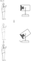
- FIGS. 5A and 5B are diagrams illustrating an example positioning operation based on a sensed user according to an example embodiment.
- the controller 140 may control the driver 150 so that the sound output unit 110 is in the first posture.
- the controller 140 may not change the posture of the sound output unit 110.
- the controller 140 may recognize a face of a user and sense only the user of which face is recognized as a valid user. For example, if a user watches the right direction, not the speaker 100 direction in FIG. 5B , the controller 140 may determine only the user at the left as a valid user and not change the posture of the sound output unit 110.
- the controller 140 may sense the corresponding user as a valid user.
- the controller 140 may determine the valid user based on the movement of a user. For example, if a movement is not sensed for more than a predetermined time such as the case in which a left user fell asleep in the state such as FIG. 5B , the controller 140 may exclude the user at the left from the valid user. Accordingly, the controller 140 may control the driver 150 so that the sound output unit 110 is in the second posture. Here, the controller 140 may control the driver 150 so that the sound emission hole of the sound output unit 110 faces the user at the right.
- the speaker 100 may further include the storage in which registered user information is stored.
- the controller 140 may determine whether the sensed user is a valid user based on whether there is user information corresponding to the sensed user among the registered user information stored in the storage.
- the storage may be implemented, for example, and without limitation, to be a storing medium such as a memory, and any apparatus which may store data.
- the storage may further store a priority order information of registered users.
- the storage 140 may determine the posture of the sound output unit 110 based on the priority order information stored in the storage.
- the controller 140 may control the driver 150 so that the sound output unit 110 is in the first posture.
- the sensor 160 may sense a thing.
- the controller 140 may sense a thing such as a wall through the sensor 160 and in this case, the controller 140 may control the driver 150 so that the sound output unit 110 is in the second position because one side of the speaker 100 is a wall.
- the controller 140 may control the driver 150 so that the sound emission hole of the sound output unit 110 faces an opposite direction of the wall.
- FIG. 6 is a diagram illustrating an operation of the speaker 100 based on the movement of a location of a user according to an example embodiment.
- the driver 150 of the speaker 100 includes the second motor which swivels the sound output unit 110 in a horizontal direction.
- the controller 140 may sense one user at the left side and control the driver 150 so that the sound output unit 110 is in the second posture.
- the controller 140 may swivel the sound output unit 110 to correspond to the location of the changed user's location.
- the controller 140 may determine the posture of the sound output unit 110 based on the distance from a user. For example, if a user moves far away from the speaker 100 more than a predetermined distance when the sound output unit 110 is in the first posture, the controller 140 may control the driver 150 so that the sound output unit 110 is in the second posture. That is, as a user moves far, a user may listen sound easily through a front emission.
- FIG. 7 is a diagram illustrating an example operation of the speaker 100 regarding the electronic apparatus that provides a signal according to an example embodiment.
- the controller 140 is configured to determine the posture of the sound output unit 110 based on the location of the electronic apparatus that provides a signal including sound. For example, as illustrated in FIG. 7 , the controller 140 may control the driver 150 based on the location of the electronic apparatus at the right that provides a signal including sound, so that the sound output unit 110 is in the second posture. Here, the controller 140 may control the driver 150 so that the sound emission hole of the sound output unit 110 faces the right side.
- FIGS. 8A and 8B are diagrams illustrating an example structure of the speaker 100 according to another example embodiment.
- the sound emission unit 120 of the speaker 100 may be attached to a ceiling. Accordingly, the first side of the sound reflector 120 having, for example, a dome shape may face a lower side, and reflect the sound emitted from the sound output unit 110 to an upper side to all directions.
- the second side which is opposite to the first side of the sound reflector 120 is formed flat to touch the ceiling.
- the second side may touch a floor. That is, a user may dispose the speaker 100 so that the second side of the sound reflector 120 touches one of the ceiling and the floor.
- FIGS. 9A and 9B are diagrams illustrating an example structure of the speaker 100 according to another example embodiment.
- the speaker 100 may include the first sound output unit 110-1, the second sound output unit 110-2, the first sound reflector 120-1, the second sound reflector 120-2, and the support 130.
- the first sound output unit 110-1 and the first sound reflector 120-1 may be disposed opposite to the second sound output unit 110-2 and the second sound reflector 120-2, respectively.
- the sound emitted from the second sound output unit 110-2 may be reflected in all directions by the second sound reflector 120-2.
- the controller 140 may control the driver 150 so that the first sound output unit 110-1 and the second sound output unit 110-2 are in the second posture.
- the direction of the sound emitted from the first sound output unit 110-1 and the second sound output unit 110-2 may be opposite to each other.
- the controller 140 may stop one operation of the first sound output unit 110-1 and the second sound output unit 110-2 if the first sound output unit 110-1 and the second sound output unit 110-2 are in the second posture. For example, if the first sound output unit 110-1 and the second sound output unit 110-2 are in the second posture, the controller 140 may stop one operation of the first sound output unit 110-1 and the second sound output unit 110-2 based on the location of the sensed user.
- FIG. 10 is a flowchart illustrating an example method of operating the speaker according to an example embodiment.
- a method for operating a speaker that includes a sound output unit comprising sound output circuitry and including a sound emission hole at one side, a sound reflector disposed at a lower side of the sound output unit and being spaced apart from the sound output unit, the sound reflector having a dome shaped upper side, and a support including one end fixed to the sound reflector and another end rotatably supporting the sound output unit, the method including: emitting sound by the sound output unit positioned in any one of a first posture in which the sound emission hole faces the upper side of the sound reflector and a second posture in which the sound emission hole does not face the upper side of the sound reflector in S1010.
- the sound output unit is positioned in another one of the first posture and the second posture and emits sound in S1020.
- the second posture may be a posture in which the sound emission hole faces a direction vertical to a direction of the sound emission hole facing the upper side of the sound reflector.
- the emitting the sound by being positioned in another one of the first posture and the second posture, S1020 comprises changing a posture of the sound output unit and changing at least one of a volume and an intensity of each frequency of the sound.
- the method may further include sensing a user and positioning the sound output unit in one of the first posture and the second posture based on at least one of a number and a location of the sensed user.
- the positioning may comprise positioning the sound output unit in the first posture if the number of the sensed user is equal to or greater than a predetermined number, and positioning the sound output unit in the second posture if the number of the sensed user is less than the predetermined number.
- the emitting the sound further comprises positioning the sound output unit in one of the first posture and the second posture by tilting the sound output unit, and swiveling the sound output unit in a horizontal direction if the sound output unit is in the second posture.
- the method further includes receiving a signal that includes the sound, outputting the received signal via the sound output unit, and positioning the sound output unit in the second posture based on a location of an electronic apparatus that provides the signal.
- the method may further include receiving a user command, and positioning the sound output unit in one of the first posture and the second posture according to the received user command.
- the sound output in the first posture may be reflected by the sound reflector to be emitted in all directions.
- the speaker may change the posture of the sound output unit and if the sound output unit is in a specific posture, the sound output from the sound output unit is reflected in all directions by the sound reflector and thus there may be an effect that a front emission or 360 degrees emission could be selected.
Landscapes
- Health & Medical Sciences (AREA)
- Otolaryngology (AREA)
- Engineering & Computer Science (AREA)
- Signal Processing (AREA)
- Physics & Mathematics (AREA)
- Acoustics & Sound (AREA)
- Multimedia (AREA)
- Obtaining Desirable Characteristics In Audible-Bandwidth Transducers (AREA)
- Circuit For Audible Band Transducer (AREA)
- Stereophonic System (AREA)
Claims (12)
- Haut-parleur (100) comprenant :un communicateur (170) comprenant des circuits de communication,une unité de sortie sonore (110) comprenant des circuits de sortie sonore et comprenant un trou d'émission sonore disposé d'un côté ;un dispositif d'entraînement (150) comprenant un premier moteur et un second moteur configurés pour entraîner l'unité de sortie sonore (110) en rotation ;un réflecteur sonore (120) disposé sur un côté inférieur de l'unité de sortie sonore et étant espacé de l'unité de sortie sonore, le réflecteur sonore ayant un côté supérieur en forme de dôme convexe ;un support (130) possédant une extrémité fixée au réflecteur sonore et une autre extrémité supportant de manière rotative l'unité de sortie sonore ; etun dispositif de commande (140) configuré pour commander au dispositif d'entraînement (150) de positionner l'unité de sortie sonore (110) dans l'une d'une première position dans laquelle le trou d'émission sonore fait face au côté supérieur du réflecteur sonore et d'une seconde position dans laquelle le trou d'émission sonore ne fait pas face au côté supérieur du réflecteur sonore,dans lequel le dispositif de commande (140) est configuré pour commander au premier moteur de positionner l'unité de sortie sonore dans l'une de la première position et de la seconde position en inclinant l'unité de sortie sonore, et pour commander au second moteur de faire pivoter l'unité de sortie sonore dans la seconde position, etdans lequel, lorsque l'unité de sortie sonore (110) est dans la seconde position, le dispositif de commande (140) est configuré pour, sur la base d'un signal qui comprend un son reçu d'un appareil électronique via le communicateur, identifier un emplacement de l'appareil électronique, et commander au dispositif d'entraînement (150) de positionner l'unité de sortie sonore (110) dans une direction faisant face à l'appareil électronique.
- Haut-parleur (100) selon la revendication 1, dans lequel la seconde position comprend une position dans laquelle le trou d'émission sonore fait face à une direction perpendiculaire à une direction du trou d'émission sonore faisant face au côté supérieur du réflecteur sonore (120).
- Haut-parleur (100) selon la revendication 1, dans lequel :
le dispositif de commande (140) est configuré pour ajuster au moins l'un d'un volume et d'une intensité de chaque fréquence de son en sortie pour qu'il soit différent dans chacune de la première position et de la seconde position. - Haut-parleur (100) selon la revendication 1, comprenant en outre :un capteur (160) ;dans lequel le dispositif de commande (140) est configuré pour commander au dispositif d'entraînement (150) de positionner l'unité de sortie sonore (110) dans l'une de la première position et de la seconde position sur la base d'au moins l'un d'un nombre et d'un emplacement d'un utilisateur détecté par le capteur.
- Haut-parleur (100) selon la revendication 4, dans lequel le dispositif de commande (140) est configuré pour commander au dispositif d'entraînement (150) de positionner l'unité de sortie sonore (110) dans la première position sur la base du fait que le nombre de l'utilisateur détecté soit égal ou supérieur à un nombre prédéterminé, et pour commander au dispositif d'entraînement de positionner l'unité de sortie sonore dans la seconde position sur la base du fait que le nombre de l'utilisateur détecté soit inférieur au nombre prédéterminé.
- Haut-parleur (100) selon la revendication 1,
dans lequel le dispositif de commande (140) est configuré pour commander à l'unité de sortie sonore (110) de sortir le signal reçu. - Haut-parleur (100) selon la revendication 1,
dans lequel la sortie sonore dans la première position est réfléchie par le réflecteur sonore (120) pour être émise dans toutes les directions. - Procédé de fonctionnement du haut-parleur de la revendication 1, le procédé comprenant :l'émission d'un son par l'unité de sortie sonore qui est positionnée dans l'une quelconque de la première position dans laquelle le trou d'émission sonore fait face au côté supérieur du réflecteur sonore et de la seconde position dans laquelle le trou d'émission sonore ne fait pas face au côté supérieur du réflecteur sonore ;le positionnement, par le dispositif d'entraînement, de l'unité de sortie sonore dans une autre de la première position et la seconde position et l'émission du son ;lorsque l'unité de sortie sonore (110) est dans la seconde position, sur la base du fait que le signal qui comprend le son soit reçu de l'appareil électronique, l'identification de l'emplacement de l'appareil électronique ; etle positionnement, par le dispositif d'entraînement, de l'unité de sortie sonore dans la direction faisant face à l'appareil électronique.
- Procédé selon la revendication 8, dans lequel la seconde position comprend une position dans laquelle le trou d'émission sonore fait face à une direction perpendiculaire à une direction du trou d'émission sonore faisant face au côté supérieur du réflecteur sonore.
- Procédé selon la revendication 8, dans lequel l'émission du son en étant positionné dans une autre d'une première position et d'une seconde position comprend le changement d'une position de l'unité de sortie sonore et le changement d'au moins l'un d'un volume et d'une intensité de chaque fréquence du son.
- Procédé selon la revendication 8, comprenant en outre :la détection d'un utilisateur ; etle positionnement de l'unité de sortie sonore dans l'une de la première position et de la seconde position sur la base d'au moins l'un d'un nombre et d'un emplacement de l'utilisateur détecté.
- Procédé selon la revendication 11, dans lequel le positionnement comprend le positionnement de l'unité de sortie sonore dans la première position sur la base du fait que le nombre de l'utilisateur détecté soit égal ou supérieur à un nombre prédéterminé, et le positionnement de l'unité de sortie sonore dans la seconde position sur la base du fait que le nombre de l'utilisateur détecté soit inférieur au nombre prédéterminé.
Applications Claiming Priority (2)
| Application Number | Priority Date | Filing Date | Title |
|---|---|---|---|
| KR1020170142174A KR102367386B1 (ko) | 2017-10-30 | 2017-10-30 | 스피커 및 그 동작 방법 |
| PCT/KR2018/009438 WO2019088420A1 (fr) | 2017-10-30 | 2018-08-17 | Haut-parleur et procédé de fonctionnement associé |
Publications (3)
| Publication Number | Publication Date |
|---|---|
| EP3659348A1 EP3659348A1 (fr) | 2020-06-03 |
| EP3659348A4 EP3659348A4 (fr) | 2020-06-03 |
| EP3659348B1 true EP3659348B1 (fr) | 2025-03-12 |
Family
ID=66244971
Family Applications (1)
| Application Number | Title | Priority Date | Filing Date |
|---|---|---|---|
| EP18874828.9A Active EP3659348B1 (fr) | 2017-10-30 | 2018-08-17 | Haut-parleur et procédé de fonctionnement associé |
Country Status (5)
| Country | Link |
|---|---|
| US (1) | US10652651B2 (fr) |
| EP (1) | EP3659348B1 (fr) |
| KR (1) | KR102367386B1 (fr) |
| CN (1) | CN111226443A (fr) |
| WO (1) | WO2019088420A1 (fr) |
Families Citing this family (2)
| Publication number | Priority date | Publication date | Assignee | Title |
|---|---|---|---|---|
| USD1054430S1 (en) * | 2021-03-02 | 2024-12-17 | Walmart Apollo, Llc | Display screen with graphical user interface |
| KR102908736B1 (ko) * | 2025-01-24 | 2026-01-06 | 국립금오공과대학교 산학협력단 | 공간음향을 구현할 수 있도록 가변이 가능한 휴대형 서라운드 사운드 시스템 |
Citations (1)
| Publication number | Priority date | Publication date | Assignee | Title |
|---|---|---|---|---|
| US4850452A (en) * | 1985-03-08 | 1989-07-25 | Wolcott Henry O | Loudspeaker structure |
Family Cites Families (23)
| Publication number | Priority date | Publication date | Assignee | Title |
|---|---|---|---|---|
| US6257365B1 (en) * | 1996-08-30 | 2001-07-10 | Mediaphile Av Technologies, Inc. | Cone reflector/coupler speaker system and method |
| US6314191B1 (en) * | 2000-07-20 | 2001-11-06 | Mignon J. Smith | Fireplace accessory |
| US20030181127A1 (en) * | 2002-03-22 | 2003-09-25 | Chain Fong Toys Co.,Ltd. | Motion toy |
| JP2004072140A (ja) * | 2002-08-01 | 2004-03-04 | Hiroshi China | 全指向性バックロードホーン型スピーカー |
| JP2006025300A (ja) * | 2004-07-09 | 2006-01-26 | Pioneer Electronic Corp | スピーカ装置及びそのスピーカ装置試聴システム |
| GB0426448D0 (en) * | 2004-12-02 | 2005-01-05 | Koninkl Philips Electronics Nv | Position sensing using loudspeakers as microphones |
| US8406439B1 (en) * | 2007-04-04 | 2013-03-26 | At&T Intellectual Property I, L.P. | Methods and systems for synthetic audio placement |
| JP2009213102A (ja) | 2008-03-03 | 2009-09-17 | Kimio Hachiro | 音響機器 |
| JP4924597B2 (ja) * | 2008-12-18 | 2012-04-25 | ヤマハ株式会社 | 音波拡散装置 |
| CA2655585C (fr) * | 2009-02-26 | 2015-02-24 | Stegmeier, Robert | Haut-parleurs audio |
| US20110316768A1 (en) * | 2010-06-28 | 2011-12-29 | Vizio, Inc. | System, method and apparatus for speaker configuration |
| US20120027226A1 (en) * | 2010-07-30 | 2012-02-02 | Milford Desenberg | System and method for providing focused directional sound in an audio system |
| KR101681780B1 (ko) | 2010-08-12 | 2016-12-01 | 엘지전자 주식회사 | 스피커 시스템 |
| JP5656791B2 (ja) * | 2011-09-29 | 2015-01-21 | 株式会社オーディオテクニカ | ホーン型スピーカ |
| US20130083537A1 (en) * | 2011-10-04 | 2013-04-04 | Ronald Paul Harwood | Acoustically transparent luminaire lens for media assemblies |
| TWI471017B (zh) * | 2012-09-06 | 2015-01-21 | Wistron Corp | 喇叭模組及其相關電子裝置 |
| CN104661159B (zh) * | 2013-11-19 | 2017-12-15 | 中山市云创知识产权服务有限公司 | 扬声器 |
| KR102211341B1 (ko) | 2014-07-09 | 2021-02-03 | 엘지전자 주식회사 | 디스플레이 장치 |
| US9838789B2 (en) | 2014-09-27 | 2017-12-05 | Robert Merz | Honeycomb speaker system |
| US20160117962A1 (en) | 2014-10-22 | 2016-04-28 | Samsung Electronics Co., Ltd. | Display apparatus and display method thereof |
| US9544681B2 (en) * | 2015-01-31 | 2017-01-10 | Bose Corporation | Acoustic deflector for omni-directional speaker system |
| KR101718044B1 (ko) | 2015-09-03 | 2017-03-20 | 엘지전자 주식회사 | 음향 출력장치 |
| JP3203919U (ja) | 2015-10-22 | 2016-04-28 | 中島 孝嗣 | 2ウェイ全指向性バックロードホーンスピーカーシステム |
-
2017
- 2017-10-30 KR KR1020170142174A patent/KR102367386B1/ko active Active
-
2018
- 2018-08-17 EP EP18874828.9A patent/EP3659348B1/fr active Active
- 2018-08-17 WO PCT/KR2018/009438 patent/WO2019088420A1/fr not_active Ceased
- 2018-08-17 CN CN201880067431.6A patent/CN111226443A/zh active Pending
- 2018-08-29 US US16/115,760 patent/US10652651B2/en active Active
Patent Citations (1)
| Publication number | Priority date | Publication date | Assignee | Title |
|---|---|---|---|---|
| US4850452A (en) * | 1985-03-08 | 1989-07-25 | Wolcott Henry O | Loudspeaker structure |
Also Published As
| Publication number | Publication date |
|---|---|
| KR20190047852A (ko) | 2019-05-09 |
| CN111226443A (zh) | 2020-06-02 |
| EP3659348A1 (fr) | 2020-06-03 |
| US10652651B2 (en) | 2020-05-12 |
| EP3659348A4 (fr) | 2020-06-03 |
| WO2019088420A1 (fr) | 2019-05-09 |
| KR102367386B1 (ko) | 2022-02-25 |
| US20190132671A1 (en) | 2019-05-02 |
Similar Documents
| Publication | Publication Date | Title |
|---|---|---|
| KR102367837B1 (ko) | 디스플레이 장치 | |
| US20250344266A1 (en) | Controlling electronic devices based on wireless ranging | |
| US11806862B2 (en) | Robots, methods, computer programs, computer-readable media, arrays of microphones and controllers | |
| CN108600059B (zh) | 设备控制方法及相关产品 | |
| KR102716152B1 (ko) | 모듈형 가정용 로봇 | |
| KR101850825B1 (ko) | 이동 단말기 및 그 제어방법 | |
| US10889002B2 (en) | Multi-device robot control | |
| TW201828282A (zh) | 語音控制裝置、系統及控制方法 | |
| KR20210058908A (ko) | 오디오 재생 및 수집 방법, 장치 및 디바이스 및 판독 가능한 저장 매체 | |
| CN105306850A (zh) | 显示装置 | |
| US12307064B2 (en) | Electronic device comprising expandable display, and method for providing content of electronic device | |
| CN111479219B (zh) | 移动通信方法、装置、终端及存储介质 | |
| KR20220063576A (ko) | 전자 장치 및 그 동작 방법 | |
| US10523859B2 (en) | Portable camera and controlling method thereof | |
| EP3659348B1 (fr) | Haut-parleur et procédé de fonctionnement associé | |
| US12457499B2 (en) | Home toy magic wand management platform interacting with toy magic wands of visitors | |
| JP5983332B2 (ja) | 音声情報報知装置、音声情報報知方法およびプログラム | |
| CN111885466B (zh) | 扬声器结构及电子设备 | |
| CN108351681A (zh) | 电子设备及其托架 | |
| CN107995416B (zh) | 一种焦距调节方法及移动终端 | |
| US11216233B2 (en) | Methods and systems for replicating content and graphical user interfaces on external electronic devices | |
| KR20240001642A (ko) | 전자 장치 및 전자 장치의 확장 디스플레이 설정 방법 | |
| KR102908736B1 (ko) | 공간음향을 구현할 수 있도록 가변이 가능한 휴대형 서라운드 사운드 시스템 | |
| KR20170129496A (ko) | 이동 로봇 | |
| JP2016058799A (ja) | 制御装置、位置情報通知装置、通信システム、制御方法及び制御プログラム |
Legal Events
| Date | Code | Title | Description |
|---|---|---|---|
| STAA | Information on the status of an ep patent application or granted ep patent |
Free format text: STATUS: THE INTERNATIONAL PUBLICATION HAS BEEN MADE |
|
| PUAI | Public reference made under article 153(3) epc to a published international application that has entered the european phase |
Free format text: ORIGINAL CODE: 0009012 |
|
| STAA | Information on the status of an ep patent application or granted ep patent |
Free format text: STATUS: REQUEST FOR EXAMINATION WAS MADE |
|
| 17P | Request for examination filed |
Effective date: 20200227 |
|
| A4 | Supplementary search report drawn up and despatched |
Effective date: 20200420 |
|
| AK | Designated contracting states |
Kind code of ref document: A1 Designated state(s): AL AT BE BG CH CY CZ DE DK EE ES FI FR GB GR HR HU IE IS IT LI LT LU LV MC MK MT NL NO PL PT RO RS SE SI SK SM TR |
|
| AX | Request for extension of the european patent |
Extension state: BA ME |
|
| DAV | Request for validation of the european patent (deleted) | ||
| DAX | Request for extension of the european patent (deleted) | ||
| STAA | Information on the status of an ep patent application or granted ep patent |
Free format text: STATUS: EXAMINATION IS IN PROGRESS |
|
| 17Q | First examination report despatched |
Effective date: 20210408 |
|
| GRAP | Despatch of communication of intention to grant a patent |
Free format text: ORIGINAL CODE: EPIDOSNIGR1 |
|
| STAA | Information on the status of an ep patent application or granted ep patent |
Free format text: STATUS: GRANT OF PATENT IS INTENDED |
|
| INTG | Intention to grant announced |
Effective date: 20241106 |
|
| GRAS | Grant fee paid |
Free format text: ORIGINAL CODE: EPIDOSNIGR3 |
|
| GRAA | (expected) grant |
Free format text: ORIGINAL CODE: 0009210 |
|
| STAA | Information on the status of an ep patent application or granted ep patent |
Free format text: STATUS: THE PATENT HAS BEEN GRANTED |
|
| AK | Designated contracting states |
Kind code of ref document: B1 Designated state(s): AL AT BE BG CH CY CZ DE DK EE ES FI FR GB GR HR HU IE IS IT LI LT LU LV MC MK MT NL NO PL PT RO RS SE SI SK SM TR |
|
| REG | Reference to a national code |
Ref country code: GB Ref legal event code: FG4D |
|
| REG | Reference to a national code |
Ref country code: CH Ref legal event code: EP |
|
| REG | Reference to a national code |
Ref country code: DE Ref legal event code: R096 Ref document number: 602018080131 Country of ref document: DE |
|
| REG | Reference to a national code |
Ref country code: IE Ref legal event code: FG4D |
|
| PG25 | Lapsed in a contracting state [announced via postgrant information from national office to epo] |
Ref country code: RS Free format text: LAPSE BECAUSE OF FAILURE TO SUBMIT A TRANSLATION OF THE DESCRIPTION OR TO PAY THE FEE WITHIN THE PRESCRIBED TIME-LIMIT Effective date: 20250612 |
|
| PG25 | Lapsed in a contracting state [announced via postgrant information from national office to epo] |
Ref country code: FI Free format text: LAPSE BECAUSE OF FAILURE TO SUBMIT A TRANSLATION OF THE DESCRIPTION OR TO PAY THE FEE WITHIN THE PRESCRIBED TIME-LIMIT Effective date: 20250312 |
|
| PG25 | Lapsed in a contracting state [announced via postgrant information from national office to epo] |
Ref country code: ES Free format text: LAPSE BECAUSE OF FAILURE TO SUBMIT A TRANSLATION OF THE DESCRIPTION OR TO PAY THE FEE WITHIN THE PRESCRIBED TIME-LIMIT Effective date: 20250312 |
|
| REG | Reference to a national code |
Ref country code: LT Ref legal event code: MG9D |
|
| PG25 | Lapsed in a contracting state [announced via postgrant information from national office to epo] |
Ref country code: NO Free format text: LAPSE BECAUSE OF FAILURE TO SUBMIT A TRANSLATION OF THE DESCRIPTION OR TO PAY THE FEE WITHIN THE PRESCRIBED TIME-LIMIT Effective date: 20250612 |
|
| PG25 | Lapsed in a contracting state [announced via postgrant information from national office to epo] |
Ref country code: HR Free format text: LAPSE BECAUSE OF FAILURE TO SUBMIT A TRANSLATION OF THE DESCRIPTION OR TO PAY THE FEE WITHIN THE PRESCRIBED TIME-LIMIT Effective date: 20250312 |
|
| REG | Reference to a national code |
Ref country code: NL Ref legal event code: MP Effective date: 20250312 |
|
| PG25 | Lapsed in a contracting state [announced via postgrant information from national office to epo] |
Ref country code: LV Free format text: LAPSE BECAUSE OF FAILURE TO SUBMIT A TRANSLATION OF THE DESCRIPTION OR TO PAY THE FEE WITHIN THE PRESCRIBED TIME-LIMIT Effective date: 20250312 |
|
| PG25 | Lapsed in a contracting state [announced via postgrant information from national office to epo] |
Ref country code: GR Free format text: LAPSE BECAUSE OF FAILURE TO SUBMIT A TRANSLATION OF THE DESCRIPTION OR TO PAY THE FEE WITHIN THE PRESCRIBED TIME-LIMIT Effective date: 20250613 Ref country code: BG Free format text: LAPSE BECAUSE OF FAILURE TO SUBMIT A TRANSLATION OF THE DESCRIPTION OR TO PAY THE FEE WITHIN THE PRESCRIBED TIME-LIMIT Effective date: 20250312 |
|
| REG | Reference to a national code |
Ref country code: AT Ref legal event code: MK05 Ref document number: 1776029 Country of ref document: AT Kind code of ref document: T Effective date: 20250312 |
|
| PG25 | Lapsed in a contracting state [announced via postgrant information from national office to epo] |
Ref country code: NL Free format text: LAPSE BECAUSE OF FAILURE TO SUBMIT A TRANSLATION OF THE DESCRIPTION OR TO PAY THE FEE WITHIN THE PRESCRIBED TIME-LIMIT Effective date: 20250312 |
|
| PG25 | Lapsed in a contracting state [announced via postgrant information from national office to epo] |
Ref country code: SE Free format text: LAPSE BECAUSE OF FAILURE TO SUBMIT A TRANSLATION OF THE DESCRIPTION OR TO PAY THE FEE WITHIN THE PRESCRIBED TIME-LIMIT Effective date: 20250312 |
|
| PG25 | Lapsed in a contracting state [announced via postgrant information from national office to epo] |
Ref country code: SM Free format text: LAPSE BECAUSE OF FAILURE TO SUBMIT A TRANSLATION OF THE DESCRIPTION OR TO PAY THE FEE WITHIN THE PRESCRIBED TIME-LIMIT Effective date: 20250312 |
|
| PG25 | Lapsed in a contracting state [announced via postgrant information from national office to epo] |
Ref country code: PT Free format text: LAPSE BECAUSE OF FAILURE TO SUBMIT A TRANSLATION OF THE DESCRIPTION OR TO PAY THE FEE WITHIN THE PRESCRIBED TIME-LIMIT Effective date: 20250714 |
|
| PGFP | Annual fee paid to national office [announced via postgrant information from national office to epo] |
Ref country code: DE Payment date: 20250721 Year of fee payment: 8 |
|
| PG25 | Lapsed in a contracting state [announced via postgrant information from national office to epo] |
Ref country code: PL Free format text: LAPSE BECAUSE OF FAILURE TO SUBMIT A TRANSLATION OF THE DESCRIPTION OR TO PAY THE FEE WITHIN THE PRESCRIBED TIME-LIMIT Effective date: 20250312 Ref country code: IT Free format text: LAPSE BECAUSE OF FAILURE TO SUBMIT A TRANSLATION OF THE DESCRIPTION OR TO PAY THE FEE WITHIN THE PRESCRIBED TIME-LIMIT Effective date: 20250312 |
|
| PG25 | Lapsed in a contracting state [announced via postgrant information from national office to epo] |
Ref country code: AT Free format text: LAPSE BECAUSE OF FAILURE TO SUBMIT A TRANSLATION OF THE DESCRIPTION OR TO PAY THE FEE WITHIN THE PRESCRIBED TIME-LIMIT Effective date: 20250312 |
|
| PG25 | Lapsed in a contracting state [announced via postgrant information from national office to epo] |
Ref country code: EE Free format text: LAPSE BECAUSE OF FAILURE TO SUBMIT A TRANSLATION OF THE DESCRIPTION OR TO PAY THE FEE WITHIN THE PRESCRIBED TIME-LIMIT Effective date: 20250312 Ref country code: CZ Free format text: LAPSE BECAUSE OF FAILURE TO SUBMIT A TRANSLATION OF THE DESCRIPTION OR TO PAY THE FEE WITHIN THE PRESCRIBED TIME-LIMIT Effective date: 20250312 |
|
| PG25 | Lapsed in a contracting state [announced via postgrant information from national office to epo] |
Ref country code: RO Free format text: LAPSE BECAUSE OF FAILURE TO SUBMIT A TRANSLATION OF THE DESCRIPTION OR TO PAY THE FEE WITHIN THE PRESCRIBED TIME-LIMIT Effective date: 20250312 |
|
| PG25 | Lapsed in a contracting state [announced via postgrant information from national office to epo] |
Ref country code: SK Free format text: LAPSE BECAUSE OF FAILURE TO SUBMIT A TRANSLATION OF THE DESCRIPTION OR TO PAY THE FEE WITHIN THE PRESCRIBED TIME-LIMIT Effective date: 20250312 |
|
| PG25 | Lapsed in a contracting state [announced via postgrant information from national office to epo] |
Ref country code: IS Free format text: LAPSE BECAUSE OF FAILURE TO SUBMIT A TRANSLATION OF THE DESCRIPTION OR TO PAY THE FEE WITHIN THE PRESCRIBED TIME-LIMIT Effective date: 20250712 |
|
| REG | Reference to a national code |
Ref country code: DE Ref legal event code: R097 Ref document number: 602018080131 Country of ref document: DE |
|
| PG25 | Lapsed in a contracting state [announced via postgrant information from national office to epo] |
Ref country code: DK Free format text: LAPSE BECAUSE OF FAILURE TO SUBMIT A TRANSLATION OF THE DESCRIPTION OR TO PAY THE FEE WITHIN THE PRESCRIBED TIME-LIMIT Effective date: 20250312 |
|
| PLBE | No opposition filed within time limit |
Free format text: ORIGINAL CODE: 0009261 |
|
| STAA | Information on the status of an ep patent application or granted ep patent |
Free format text: STATUS: NO OPPOSITION FILED WITHIN TIME LIMIT |
|
| REG | Reference to a national code |
Ref country code: CH Ref legal event code: L10 Free format text: ST27 STATUS EVENT CODE: U-0-0-L10-L00 (AS PROVIDED BY THE NATIONAL OFFICE) Effective date: 20260121 |
|
| 26N | No opposition filed |
Effective date: 20251215 |
|
| REG | Reference to a national code |
Ref country code: CH Ref legal event code: H13 Free format text: ST27 STATUS EVENT CODE: U-0-0-H10-H13 (AS PROVIDED BY THE NATIONAL OFFICE) Effective date: 20260324 |
|
| PG25 | Lapsed in a contracting state [announced via postgrant information from national office to epo] |
Ref country code: MC Free format text: LAPSE BECAUSE OF FAILURE TO SUBMIT A TRANSLATION OF THE DESCRIPTION OR TO PAY THE FEE WITHIN THE PRESCRIBED TIME-LIMIT Effective date: 20250312 |
|
| PG25 | Lapsed in a contracting state [announced via postgrant information from national office to epo] |
Ref country code: LU Free format text: LAPSE BECAUSE OF NON-PAYMENT OF DUE FEES Effective date: 20250817 |
|
| PG25 | Lapsed in a contracting state [announced via postgrant information from national office to epo] |
Ref country code: CH Free format text: LAPSE BECAUSE OF NON-PAYMENT OF DUE FEES Effective date: 20250831 |