EP3659469A1 - Boxspringbett - Google Patents
Boxspringbett Download PDFInfo
- Publication number
- EP3659469A1 EP3659469A1 EP19211444.5A EP19211444A EP3659469A1 EP 3659469 A1 EP3659469 A1 EP 3659469A1 EP 19211444 A EP19211444 A EP 19211444A EP 3659469 A1 EP3659469 A1 EP 3659469A1
- Authority
- EP
- European Patent Office
- Prior art keywords
- box spring
- frame
- spar
- side rail
- mounting bracket
- Prior art date
- Legal status (The legal status is an assumption and is not a legal conclusion. Google has not performed a legal analysis and makes no representation as to the accuracy of the status listed.)
- Granted
Links
Images


Classifications
-
- A—HUMAN NECESSITIES
- A47—FURNITURE; DOMESTIC ARTICLES OR APPLIANCES; COFFEE MILLS; SPICE MILLS; SUCTION CLEANERS IN GENERAL
- A47C—CHAIRS; SOFAS; BEDS
- A47C23/00—Spring mattresses with rigid frame or forming part of the bedstead, e.g. box springs; Divan bases; Slatted bed bases
- A47C23/005—Spring mattresses with rigid frame or forming part of the bedstead, e.g. box springs; Divan bases; Slatted bed bases foldable or dismountable
-
- A—HUMAN NECESSITIES
- A47—FURNITURE; DOMESTIC ARTICLES OR APPLIANCES; COFFEE MILLS; SPICE MILLS; SUCTION CLEANERS IN GENERAL
- A47C—CHAIRS; SOFAS; BEDS
- A47C19/00—Bedsteads
- A47C19/02—Parts or details of bedsteads not fully covered in a single one of the following subgroups, e.g. bed rails, post rails
- A47C19/021—Bedstead frames
- A47C19/022—Head or foot boards
-
- A—HUMAN NECESSITIES
- A47—FURNITURE; DOMESTIC ARTICLES OR APPLIANCES; COFFEE MILLS; SPICE MILLS; SUCTION CLEANERS IN GENERAL
- A47C—CHAIRS; SOFAS; BEDS
- A47C23/00—Spring mattresses with rigid frame or forming part of the bedstead, e.g. box springs; Divan bases; Slatted bed bases
- A47C23/06—Spring mattresses with rigid frame or forming part of the bedstead, e.g. box springs; Divan bases; Slatted bed bases using wooden springs, e.g. of slat type ; Slatted bed bases
Definitions
- the present invention relates to a box spring according to the preamble of claim 1.
- a box spring is part of a bed known as a box spring bed that is used for resting, especially for sleeping.
- a box spring bed includes the box spring, a mattress, as well as feet attached under the box spring and optionally a topper and / or a headboard.
- the mattress is placed on a single bed on one and on a double bed on two box springs.
- the box spring thus serves as a spring base for the actual mattress, so that the sleeper lies on a double spring base.
- a large number of springs, in particular pocket spring cores, are provided in the suspension over the surface.
- this combination of surface-elastic support by means of the suspension and point-elastic support by means of the mattress creates a particularly good and relaxing lying feeling for someone resting on the box spring bed.
- the box spring with its feet and the mattress arranged thereon provides a box spring bed with a lying surface raised from the floor, which makes getting up and lying down easier.
- Inter IKEA Systems B.V. sells a box spring for a box spring bed under the name ESPEV ⁇ R.
- ESPEV ⁇ R From the assembly instructions 103.071.65 / AA-1793786-3 for the box spring ESPEV ⁇ R is a box spring comprising a suspension, a frame with attachable feet, a support made of a number of crossbars to support the suspension and a cover to fix the suspension on Frame known.
- the box spring ESPEV ⁇ R is broken down into its component parts in a carton or packed in several cartons and handed over to the customer in a pick-up market. This enables space-saving storage and inexpensive transportation of the box spring.
- the box spring is then assembled at the customer's home using the assembly instructions mentioned above.
- the present invention is based on the object of creating a box spring of the type mentioned at the outset, which can be delivered to the customer at low cost and which the customer can easily assemble without great effort.
- a box spring designed according to this technical teaching has the advantage that the right side spar and the left side spar are of split design and are each composed of a first side spar element and a second side spar element, so that the dimensions of the side spars of the box spring are significantly reduced.
- a mounting bracket for receiving the attachable side rail elements enables a stable connection of the side rail elements to form the frame.
- Such a box spring broken down into its individual parts has the advantage that its individual parts have dimensions of less than 120 cm. This makes it possible to accommodate the frame and the corresponding rolled-up suspension in a package smaller than 80cm x 80cm x 120 cm, so that inexpensive mailing is possible.
- the customer only needs to connect the individual parts together to form a frame.
- slats can be attached to the frame to form a support and the suspension can be placed on it.
- the suspension can then be attached to the frame with the cover to get a finished box spring. This eliminates the need for time-consuming and expensive transport, while inexpensive mail transport is made possible, and the box spring can also be assembled more easily at the point of use.
- the frame has a central crossbeam which can be fastened on the one hand to the right mounting bracket and on the other hand to the left mounting bracket. This creates a particularly stable frame, in particular because the loads that occur are diverted to the central crossmember and further to the feet via the mounting hardware.
- the right and / or the left mounting bracket has a U-shaped spar bracket for receiving both the first side spar element and the second side spar element.
- the open side of the spar bracket is oriented outwards. It is advantageous that the spar elements can be easily inserted from the outside into the U-shaped profile and are held and supported in the profile. This creates a particularly stable connection between the first side rail element and the second side rail element.
- the right and / or the left mounting bracket has a U-shaped crossbar holder for receiving the central crossbar.
- the open side of the truss holder is expediently oriented downwards and inwards. This alignment means that loads are transferred from the side rail to the mounting element, the center crossbar and the feet derived the soil. This creates a stable box spring in which a user can also sit down in the area of the side rail.
- crossbars can be attached to the side rails running orthogonally to the side rails. As a result, loads that act on the suspension are distributed to the frame.
- the head traverse and / or the central traverse and / or the foot traverse expediently has means for receiving a foot, in particular a threaded sleeve.
- the threaded sleeve makes it easy to attach and detach the foot. Attaching feet to the crossbeams has the advantage that loads in the area where there is a rest are transferred directly into the ground.
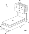
- a box spring bed 10 is shown in an exploded view.
- the box spring bed 10 comprises a box spring 12 arranged one above the other, a mattress 14 resting on the box spring 12, a topper 16 resting on the mattress 14, as well as a plurality of feet 18 attached to the bottom of the box spring 12 and a head part 20 held on the head end of the box spring 12 20 are on a side facing the box spring 12 at the top two small and a large pillow 21 below.
- the head part 20 comprises a cover 80 and a linkage 76.
- Fig. 2 shows an exploded view of the box spring 12 with a frame 36, a support 28 formed from crossbars 72, a suspension 29, and a cover 34.
- the frame 36 comprises a right side member 44a, a left side member 44b, and a central cross member 23, a head cross member 24, a foot traverse 25 and a right mounting bracket 50a.
- the support 28 rests on the frame 36 and supports the suspension 29, wherein the cover 34 covers the suspension 29 and extends up to and to the right and left side rails 44a, b of the frame 36 it is fastened by means of a hook-and-eye connection (not known here), which is not shown here.
- the suspension 29 comprises a multiplicity of compression springs, in particular pocket spring cores, which are encased by an upholstery (not shown here).
- the total of six feet 18 are attached to an underside of the frame 36, four at each corner and two invisible in this view in the middle of the frame 36.
- Fig. 3 shows a plan view of the frame 36 and the crossbars 72 in an exploded view.
- the right side rail 44a and the left side rail 44b each comprise a first side rail element 48a and a second side rail element 48b.
- the first and second side rail elements 48a, b can each be connected to one another by attachment to the right and left mounting brackets 50a, b.
- the central crossbar 23 can be attached to the right and left mounting brackets 50a, b.
- the head traverse 24 is arranged attachable between the first side rail elements 48a of the right and left side rails 44a, b.
- the foot traverse 25 is arranged such that it can be attached between the second side rail elements 48b of the right and left side rails 44a, b.
- the mounting bracket 50a, b is shown with a spar holder 53 and a crossbar holder 54.
- the U-shaped profile of the spar holder 53 serves to receive the first and second side rail elements, not shown here.
- the U-shaped profile of the truss bracket 54 serves to accommodate the central crossbar, not shown here.
- the spar bracket 53 and the truss bracket 54 have a contact surface 55 on a part of the U-shaped profile arranged in the direction of the upper side 59.
- Fig. 5 shows the frame 36 in the assembled state with crossbars 72 fastened to an upper side 59 of the frame 36.
- the head traverse 24 and the foot traverse 25 are arranged between the right side rail 44a and the left side rail 44b and fastened to them by a screw connection.
- Ends of the central crossbeam 23 are inserted and screwed into the crossbar holders 54 of the right and left mounting fittings 53a, b.
- the first and second side spar elements 48a, b of the right side spar 44a are fastened in the spar holder 53 of the right mounting bracket 50a by means of a screw connection.
- the first and second side spar elements 48a, b of the left side spar 44b are fastened in the spar holder 53 of the left mounting bracket 50b by means of a screw connection.
- two feet 18 are screwed onto an underside 61 of the frame 36 in the area of the side bars 44a, b in receiving sleeves of the central crossbar 23, head crossbar 24 and foot crossbar 25.
- Fig. 6 schematically shows a perspective view of a frame 36 loaded with a load 74 and how this load 74 is derived.
- the load 74 acting on the upper side 59 of the left side rail 44b is diverted via the left mounting bracket 50b and the central crossbar 23 into the foot 18 attached to it.
- the contact surfaces (not visible here) are formed between the left side spar 44b and the spar holder 53 and between the central crossmember 23 and the crossmember holder 54. Via these contact surfaces, the load 74 is diverted into the foot 18 attached to the underside 61 of the frame and further into a floor.
- the U-shaped profile of the crossmember holder 54 which is open in the direction of the underside 61, keeps screw connections free of loads.
- Fig. 7a shows the head part 20 in the assembled state.
- This head part comprises a linkage 76 and the cover 80, which can be pulled over the linkage 76.
- the rectangular cover 80 is made of textile webs joined on three sides, in particular in the form of a pocket.
- the cover 80 is designed to be open, so that it can be pulled over the linkage 76.
- the cover 80 is provided on the side facing the bed with a plurality of eyelets of a hook-and-eye connection, so that objects, in particular cushions, cushions, soft toys or the like can be attached to it with corresponding hooks of a hook-and-eye connection.
- the entire front of the cover 80 is provided with these eyelets, so that the objects can be attached to any position on the head part 20, or that several objects can be attached to the head part 20 at the same time.
- On an inner side 94 of the cover 80 three reinforcing straps 92 which are arranged around the linkage 76 and are arranged equidistantly are sewn onto the cover 80.
- the reinforcement straps 92 are pulled together with the cover 80 over the linkage 76.
- the reinforcement straps 92 arranged all around the linkage 76 enclose the linkage 76, the reinforcement straps 92 running parallel to a central rod 86 and abutting a right hand support rod 84 and a left hand support rod 85 of the linkage 76.
- the reinforcement belts 76 are commercially available 7 cm or 8 cm wide cushion belts made of jute, the tensile strength and extensibility of which are selected according to the requirements.
- the reinforcing straps 92 absorb loads that are caused by leaning on the sleeper and thus become excessive Yielding of the coating 80 counteracted. Because of this, a reinforcement strap 92 also runs in a lower half of the headboard between the center bar and the top edge of the mattress of the bed. The lower half of the headboard covers the area that, when the headboard is attached to the bed, borders directly on the top edge of the mattress.
- Fig. 7b shows the linkage 76 of the head part 20 in an exploded view, the linkage 76 comprising the central rod 86, the left handrail 85 and the right handrail 84 and a fastening rod 78, 79 on the left and the right hand holding rod 84, 85, respectively is trained.
- This fastening rod 78, 79 protrudes orthogonally from the holding rod 84, 85 and is suitable for being inserted into a corresponding receiving bore on the frame of the box spring. This keeps the head part on the box spring.
- Fig. 8 shows the head part 20 with the cover 80 and three pillows 21, two smaller pillows 21 are attached at the top of the head part 20, while a larger pillow 21 is attached at the bottom of the head part 20.
- the cover 80 is provided on a side facing the pillow 21 with eyelets of a hook-eye connection, not shown here, while the pillow 21 on a side facing the cover 80 is provided with hooks corresponding to the eyelets.
- the cushions 21 are detachably attached to the eyelets of the cover 80 by means of the hooks.
- a reinforcement belt 92 for maintaining tension is pulled together with the cover over the linkage 76 and prevents the cover 80 from being pushed through when loaded by a leaning.
Landscapes
- Invalid Beds And Related Equipment (AREA)
Abstract
Description
- Die vorliegende Erfindung betrifft ein Boxspring gemäß dem Oberbegriff des Anspruches 1.
- Ein Boxspring ist ein Teil einer als Boxspringbett bekannten Bettstatt die zum Ruhen, insbesondere zum Schlafen dient. Ein Boxspringbett umfasst das Boxspring, eine Matratze, sowie unter dem Boxspring angebrachte Füße und optional einen Topper und/oder einen Kopfteil. Dabei ist die Matratze bei einem Einzelbett auf einem und bei einem Doppelbett auf zwei Boxsprings aufgelegt. Somit dient das Boxspring als Unterfederung der eigentlichen Matratze, so dass der Schläfer auf einer doppelten Unterfederung liegt.
- In der Federung sind über die Fläche verteilt eine Vielzahl von Federn, insbesondere Taschenfederkernen, vorgesehen. Im Verbund mit der Matratze wird durch diese Kombination von flächenelastischer Stützung mittels der Federung und punktelastischer Stützung mittels der Matratze ein besonders gutes und entspannendes Liegegefühl für einen auf dem Boxspringbett Ruhenden geschaffen. Ferner ist durch das Boxspring mit seinen Füßen und mit der darauf angeordneten Matratze ein Boxspringbett mit einer vom Boden erhöhten Liegefläche bereitgestellt, wodurch ein aufstehen und hinlegen erleichtert ist.
- Die Firma Inter IKEA Systems B.V. vertreibt unter der Bezeichnung ESPEVÄR ein Boxspring für ein Boxspringbett. Aus der Montageanleitung 103.071.65/ AA-1793786-3 für das Boxspring ESPEVÄR ist ein Boxspring umfassend eine Federung, einen Rahmen mit daran anbringbaren Füßen, eine aus einer Anzahl von Querlatten gebildete Auflage zur Unterstützung der Federung und einen Bezug zur Fixierung der Federung am Rahmen bekannt.
- Das Boxspring ESPEVÄR wird in seine Bestandteile zerlegt in einen Umkarton oder in mehreren Umkartons verpackt in einem Abholmarkt an den Kunden übergeben. Hierdurch ist eine platzsparende Lagerung und ein kostengünstiger Transport des Boxsprings möglich. Der Zusammenbau des Boxsprings erfolgt dann beim Kunden zu Hause unter zu Hilfenahme der oben genannten Montageanleitung.
- Der Transport des Boxsprings vom Abholmarkt nach Hause ist für den Kunden sehr mühsam, insbesondere durch die 2 m langen Längsholme des Rahmens. Außerdem ist es für den Kunden sehr zeitraubend, für viele Kunden auch nervenaufreibend, das Boxspring selbst zusammen zu bauen, selbst wenn der Kunde die Montageanleitung zu Hilfe nimmt.
- Auch ein Versand des Boxspringes mit handelsüblichen Postpakten ist nicht möglich, weil die Längsholme 2 m lang sind und weil die verschiedenen Post- und Kurierdienste nur Pakete mit einer maximalen Größe von 80cm mal 80cm mal 120cm transportieren. Auch ein Versand mit einer Spedition ist aus Kostengründen keine Alternative.
- Davon ausgehend liegt der vorliegenden Erfindung die Aufgabe zu Grunde, ein Boxspring der eingangs genannten Art zu schaffen, welches dem Kunden kostengünstig angeliefert werden kann und welches der Kunde in einfacher Weise ohne großen Aufwand zusammenbauen kann.
- Als technische Lösung dieser Aufgabe wird erfindungsgemäß ein Boxspring mit den Merkmalen des Anspruches 1 vorgeschlagen. Vorteilhafte Weiterbildungen dieses Boxsprings sind den jeweiligen Unteransprüchen zu entnehmen.
- Ein nach dieser technischen Lehre ausgebildetes Boxspring hat den Vorteil, dass der rechte Seitenholm und der linke Seitenholm geteilt ausgeführt ist und sich jeweils aus einem ersten Seitenholmelement und einem zweiten Seitenholmelement zusammensetzt, so dass die Abmaße der Seitenholme des Boxsprings deutlich verkleinert sind. Ein Montagebeschlag zur Aufnahme der anbringbaren Seitenholmelemente ermöglicht eine Stabile Verbindung der Seitenholmelemente zur Bildung des Rahmens.
- Ein solches in seine Einzelteile zerlegtes Boxspring hat den Vorteil, dass seine Einzelteile Abmaße kleiner 120cm haben. Hierdurch ist es möglich den Rahmen und die entsprechend zusammengerollte Federung in einem Paket kleiner als 80cm x 80cm x 120 cm unterzubringen, so dass ein kostengünstiger Postversand möglich ist. Der Kunde braucht die Einzelteile nur miteinander verbinden um einen Rahmen zu bilden. In einem weiteren Schritt können Latten zur Bildung einer Auflage auf dem Rahmen angebracht werden und die Federung daraufgelegt werden. Die Federung kann dann mit dem Bezug am Rahmen befestigt werden, um ein fertiges Boxspring zu erhalten. Ein aufwendiger und teurer Transport entfällt damit während ein kostengünstiger Posttransport ermöglicht wird und außerdem ist ein einfacherer Zusammenbau des Boxsprings am Ort der Nutzung erreicht.
- In einer vorteilhaften Ausgestaltung weist der Rahmen eine Mitteltraverse auf, die einerseits am rechten Montagebeschlag und andererseits am linken Montagebeschlag befestigbar ist. Hierdurch wird ein besonders stabiler Rahmen geschaffen, insbesondere weil die auftretenden Lasten über den Montagebeschlag auf die Mitteltraverse und weiter auf die Füße abgeleitet werden.
- In einer bevorzugten Ausführungsform weist der rechte und/oder der linke Montagebeschlag eine U-förmige Holmhalterung zur Aufnahme sowohl des ersten Seitenholmelements, als auch des zweiten Seitenholmelements auf. Dabei ist die offene Seite der Holmhalterung nach außen ausgerichtet. Vorteilhaft ist dabei, dass die Holmelemente von außen einfach in das U-förmige Profil einführbar sind und in dem Profil anliegend gehalten und gestützt werden. Damit wird eine besonders stabile Verbindung zwischen dem ersten Seitenholmelement und dem zweiten Seitenholmelement geschaffen.
- Vorteilhafterweise weist der rechte und/oder der linke Montagebeschlag eine U-förmige Traversenhalterung zur Aufnahme der Mitteltraverse auf. Zweckmäßigerweise ist die offene Seite der Traversenhalterung nach unten und nach Innen ausgerichtet. Durch diese Ausrichtung werden Lasten vom Seitenholm über das Montageelement, die Mitteltraverse und die Füße in den Boden abgeleitet. Somit wird eine stabiles Boxspring geschaffen bei dem ein Nutzer sich auch im Bereich des Seitenholms hinsetzen kann.
- In einer zweckmäßigen Ausgestaltung des Boxsprings sind Querlatten orthogonal zu den Seitenholmen verlaufend auf den Seitenholmen anbringbar. Dadurch werden Lasten die auf die Federung einwirken auf den Rahmen verteilt.
- Zweckmäßigerweise weist die Kopftraverse und/oder die Mitteltraverse und/oder die Fußtraverse Mittel zur Aufnahme eines Fußes, insbesondere eine Gewindehülse, auf. Durch die Gewindehülse ist eine einfaches anbringen und lösen des Fußes ermöglicht. Eine Anbringung von Füßen an den Mitteltraversen hat den Vorteil, dass Lasten in dem Bereich wo ein ruhender liegt direkt in den Boden abgeleitet werden.
- Weitere Vorteile der erfindungsgemäßen Boxsprings ergeben sich aus der beigefügten Zeichnung und den nachstehend beschriebenen Ausführungsformen. Ebenso können die vorstehend genannten und die noch weiter ausgeführten Merkmale erfindungsgemäß jeweils einzeln oder in beliebigen Kombinationen miteinander verwendet werden. Die erwähnten Ausführungsformen sind nicht als abschließende Aufzählung zu verstehen, sondern haben vielmehr beispielhaften Charakter. Es zeigen:
- Fig. 1
- in perspektivischer Explosionsdarstellung ein Boxspringbett mit einer ersten Ausführungsform eines erfindungsgemäßen Boxsprings;
- Fig. 2
- in perspektivischer Explosionsdarstellung ein Boxspring gemäß
Fig. 1 ; - Fig. 3
- eine Draufsicht auf einen Rahmen des Boxsprings sowie eine Auflage aus Querlatten gemäß
Fig. 1 in Explosionsdarstelltung; - Fig. 4
- in perspektivischer Darstellung ein Montagebeschlag des Boxsprings gemäß
Fig. 1 ; - Fig. 5
- in perspektivischer Darstellung der zusammengebaute Rahmen des Boxsprings gemäß
Fig. 1 mit Auflage; - Fig. 6
- in perspektivischer Ansicht ein Ausschnitt des mit einer Last beaufschlagten Rahmens gemäß
Fig. 5 ; - Fig. 7a
- in perspektivischer Darstellung ein Kopfteil zur Anbringung am Boxspring gemäß
Fig. 1 mit einem Gestänge und einem einen Ausschnitt aufweisenden Überzug; - Fig. 7b
- in perspektivischer Explosionsdarstellung das Gestänge des Kopfteils gemäß
Fig. 7a ; - Fig. 8
- in perspektivischer Ansicht das Kopfteil gemäß
Fig. 7a mit daran angebrachten Kissen. - In
Fig. 1 dargestellt ist ein Boxspringbett 10 in Explosionsdarstellung. Das Boxspringbett 10 umfasst übereinander angeordnet ein Boxspring 12, eine auf dem Boxspring 12 aufliegende Matratze 14, einen auf der Matratze 14 aufliegenden Topper 16, sowie mehrere unten am Boxspring 12 angebrachte Füße 18 und ein am Kopfende Boxsprings 12 gehaltenes Kopfteil 20. An dem Kopfteil 20 sind auf einer dem Boxspring 12 zugewandten Seite oben zwei kleine und unten ein großes Kissen 21 angebracht. Das Kopfteil 20 umfasst einen Überzug 80 und ein Gestänge 76. -
Fig. 2 zeigt in einer Explosionsdarstellung das Boxspring 12 mit einem Rahmen 36, eine aus Querlatten 72 gebildete Auflage 28, einer Federung 29, sowie einem Bezug 34. Der Rahmen 36 umfasst ein rechten Seitenholm 44a, einen linken Seitenholm 44b, sowie eine Mitteltraverse 23, eine Kopftraverse 24, eine Fußtraverse 25 und einen rechten Montagebeschlag 50a aufweisen. Die Auflage 28 liegt auf dem Rahmen 36 auf und stützt die Federung 29, wobei der Bezug 34 die Federung 29 bedeckt und bis an dem rechten und dem linken Seitenholm 44a,b des Rahmens 36 reicht und an diesen mittels einer hier nicht näher dargestellten Haken-Ösen-Verbindung (umgangssprachlich auch Klett-Verschluss genannt) befestigt ist. - Die Federung 29 umfasst eine Vielzahl von Druckfedern, insbesondere Taschenfederkernen, die von einer hier nicht näher dargestellten Polsterung umhüllt sind. Die insgesamt sechs Füße 18 sind an einer Unterseite des Rahmens 36 angebracht, vier an jeder Ecke und zwei in dieser Ansicht unsichtbar in der Mitte des Rahmens 36.
-
Fig. 3 zeigt in einer Draufsicht den Rahmen 36 sowie die Querlatten 72 in einer Explosionsdarstellung. Der rechte Seitenholm 44a und der linke Seitenholm 44b umfassen jeweils ein erstes Seitenholmelement 48a und ein zweites Seitenholmelement 48b. Das erste und zweite Seitenholmelement 48a,b ist jeweils mittels Anbringung an dem rechten bzw. linken Montagebeschlag 50a,b miteinander verbindbar. Ferner ist die Mitteltraverse 23 an dem rechten und linken Montagebeschlag 50a,b anbringbar. Die Kopftraverse 24 ist zwischen den ersten Seitenholmelementen 48a des rechten und linken Seitenholms 44a, b anbringbar angeordnet. Analog dazu ist die Fußtraverse 25 zwischen den zweiten Seitenholmelementen 48b des rechten und linken Seitenholms 44a, b anbringbar angeordnet. - In
Fig. 4 dargestellt ist der Montagebeschlag 50a,b mit einer Holmhalterung 53 und einer Traversenhalterung 54. Das U-förmige Profil der Holmhalterung 53 dient zur Aufnahme der hier nicht dargestellten ersten und zweiten Seitenholmelemente. Das U-förmige Profil der Traversenhalterung 54 dient zur Aufnahme der hier nicht dargestellten Mitteltraverse. Die Holmhalterung 53 und die Traversenhalterung 54 weisen an einem in Richtung der Oberseite 59 angeordnetem Teil des U-förmigen Profils eine Kontaktfläche 55 auf. -
Fig. 5 zeigt den Rahmen 36 in zusammengebauten Zustand mit an einer Oberseite 59 des Rahmens 36 befestigten Querlatten 72. Die Kopftraverse 24 und die Fußtraverse 25 sind zwischen dem rechten Seitenholm 44a und dem linken Seitenholm 44b angeordnet und durch eine Schraubverbindung an diesen befestigt. Enden der Mitteltraverse 23 sind in die Traversenhalterungen 54 des rechten und linken Montagebeschlags 53a, b eingefügt und angeschraubt. Das erste und zweite Seitenholmelement 48a, b des rechten Seitenholms 44a sind in der Holmhalterung 53 des rechten Montagebeschlags 50a mittels Schraubverbindung befestigt. Das erste und zweite Seitenholmelement 48a, b des linken Seitenholms 44b sind in der Holmhalterung 53 des linken Montagebeschlags 50b mittels Schraubverbindung befestigt. Jeweils zwei Füße 18 sind an einer Unterseite 61 des Rahmens 36 im Bereich der Seitenholme 44a, b in Aufnahmehülsen der Mitteltraverse 23, Kopftraverse 24 und Fußtraverse 25 eingeschraubt. -
Fig. 6 zeigt in perspektivischer Ansicht schematisch einen mit einer Last 74 beaufschlagten Rahmen 36 und wie diese Last 74 abgeleitet wird. Die auf die Oberseite 59 des linken Seitenholms 44b wirkende Last 74 wird über den linken Montagebeschlag 50b und die Mitteltraverse 23 in den an dieser angebrachten Fuß 18 abgeleitet. Durch die U-förmig Ausgestaltung sind die hier nicht sichtbaren Kontaktflächen zwischen dem linken Seitenholm 44b und der Holmhalterung 53 sowie zwischen der Mitteltraverse 23 und der Traversenhalterung 54 ausgebildet. Über diese Kontaktflächen wird die Last 74 in den an der Unterseite 61 des Rahmens angebrachten Fuß 18 und weiter in einen Boden abgeleitet. Insbesondere durch das in Richtung der Unterseite 61 geöffnete U-förmige Profil der Traversenhalterung 54 werden dabei Schraubverbindung frei von Lasten gehalten. Da der Großteil der Last 74 über die Mitteltraverse 23 abgeleitet wird kann eine Verbindung zwischen der Kopftraverse 24 und dem linken Seitenholm 44b ohne einen Beschlag ausgestaltet werden. Die Last 74 die über die Kopftraverse 24 in den daran befestigten Fuß 18 abgeleitet wird ist ein Bruchteil der gesamten Last. 74. -
Fig. 7a zeigt das Kopfteil 20 in zusammengebautem Zustand. Dieses Kopfteil umfasst ein Gestänge 76 und den Überzug 80, der über das Gestänge 76 überziehbar ist. Der rechteckige Überzug 80 ist aus an drei Seiten zusammengefügten Textilbahnen gefertigt, insbesondere in Form einer Tasche. An einer vierten Seite, der Unterseite, ist der Überzug 80 offen ausgeführt, so dass ein Aufziehen über das Gestänge 76 möglich ist. Der Überzug 80 ist auf der dem Bett zugewandten Seite mit einer Vielzahl von Ösen einer Haken-Ösen-Verbindung versehen, so dass Gegenstände, insbesondere Kissen, Polster, Stofftiere oder dergleichen mit entsprechenden Hacken einer Haken-Ösen-Verbindung daran angebracht werden können. In der hier dargestellten Ausführungsform ist die komplette Vorderseite des Überzuges 80 mit diesen Ösen versehen, damit die Gegenstände an einer beliebigen Stelle des Kopfteiles 20 anbringbar sind, bzw. dass mehrere Objekte am Kopfteil 20 gleichzeitig anbringbar sind. Auf einer Innenseite 94 des Überzugs 80 sind drei um das Gestänge 76 umlaufend angeordnete und äquidistant angeordnete Verstärkungsgurte 92 an den Überzug 80 angenäht. Die Verstärkungsgurte 92 werden zusammen mit dem Überzug 80 über das Gestänge 76 aufgezogen. Die umlaufend um das Gestänge 76 angeordneten Verstärkungsgurte 92 umschließen das Gestänge 76, wobei die Verstärkungsgurte 92 parallel zu einer Mittelstange 86 verlaufen und an einer rechten Haltestange 84 und einer linken Haltestange 85 des Gestänges 76 anliegen. Die Verstärkungsgurte 76 sind handelsübliche aus Jute gefertigte 7cm oder 8cm breite Polstergurte, deren Zugfestigkeit und Dehnbarkeit den Anforderungen entsprechend gewählt ist. - Durch die Verstärkungsgurte 92 werden durch Anlehnen des Schläfers auftretende Lasten aufgenommen und somit wird einem übermäßigen Nachgeben des Überzugs 80 entgegengewirkt. Deswegen verläuft ein Verstärkungsgurt 92 auch in einer unteren Hälfte des Kopfteils zwischen der Mittelstange und der Oberkante der Matratze des Bettes. Die untere Hälfte des Kopfteils umfasst den Bereich, der wenn das Kopfteil am Bett befestigt ist, direkt an die Oberkante der Matratze grenzt.
-
Fig. 7b zeigt das Gestänge 76 des Kopfteils 20 in einer Explosionsdarstellung, wobei das Gestänge 76 die Mittelstange 86, die linke Haltestange 85 und die rechte Haltestange 84 umfasst und wobei an der linken, bzw. der rechten, Haltestange 84, 85 jeweils eine Befestigungsstange 78, 79 ausgebildet ist. Diese Befestigungsstange 78, 79 steht orthogonal von der Haltestange 84, 85 ab und ist geeignet, in eine korrespondierende Aufnahmebohrung am Rahmen des Boxsprings eingeführt zu werden. Hierdurch wird das Kopfteil am Boxspring gehalten. -
Fig. 8 zeigt das Kopfteil 20 mit dem Überzug 80 und drei Kissen 21, dabei sind zwei kleinere Kissen 21 oben am Kopfteil 20 angebracht, während ein größeres Kissen 21 unten am Kopfteil 20 angebracht ist. Der Überzug 80 ist auf einer den Kissen 21 zugewandten Seite mit hier nicht näher dargestellten Ösen einer Haken-Ösen-Verbindung versehen, während die Kissen 21 auf einer dem Überzug 80 zugewandten Seite mit den zu den Ösen korrespondierenden mit Haken versehen sind. Die Kissen 21 sind dabei mittels der Haken an den Ösen des Überzugs 80 abnehmbar angebracht. Ein Verstärkungsgurt 92 zur Erhaltung einer Spannung wird zusammen mit dem Überzug über das Gestänge 76 aufgezogen und vermeidet ein Durchdrücken des Überzugs 80 bei Belastung durch ein Anlehnen.
Claims (9)
- Ein in seine Einzelteile zerlegtes Boxspring mit einer Federung (29) und mit einem Rahmen (36) zur Unterstützung der Federung (29), wobei der Rahmen (36) einen rechten Seitenholm (44a) und einen dem rechten Seitenholm (44a) gegenüberliegenden linken Seitenholm (44b) umfasst, wobei der Rahmen (36) eine die beiden Seitenholme (44a, b) miteinander verbindende Kopftraverse (24) und eine die beiden Seitenholme (44a,b) miteinander verbindende Fußtraverse (25) umfasst und wobei der Rahmen (36) Querlatten (72) zur Unterstützung der Federung (29) umfasst,
dadurch gekennzeichnet,
dass der rechte Seitenholm (44a) geteilt ausgeführt ist und sich aus einem ersten Seitenholmelement (48a) und einem zweiten Seitenholmelement (48b) zusammensetzt und dass der Rahmen (36) einen rechten Montagebeschlag (50a) umfasst an dem das erste Seitenholmelement (48a) und das zweite Seitenholmelement (48b) anbringbar sind und/oder dass der linke Seitenholm (44b) geteilt ausgeführt ist und sich aus einem ersten Seitenholmelement (48a) und einem zweiten Seitenholmelement (48b) zusammensetzt und dass der Rahmen (36) einen linken Montagebeschlag (50b) umfasst an dem das erste Seitenholmelement (48a) und das zweite Seitenholmelement (48b) anbringbar sind. - Boxspring nach Anspruch 1,
dadurch gekennzeichnet,
dass der Rahmen (36) eine Mitteltraverse (23) aufweist, die einerseits am rechten Montagebeschlag (50a) und andererseits am linken Montagebeschlag (50b) befestigbar ist. - Boxspring nach wenigstens einem der vorangehenden Ansprüche,
dadurch gekennzeichnet,
dass der rechte und/oder der linke Montagebeschlag (50a,b) eine U-förmige Holmhalterung (53) zur Aufnahme sowohl des ersten Seitenholmelements (48a), als auch des zweiten Seitenholmelements (48b) aufweist, - Boxspring nach Anspruch 3,
dadurch gekennzeichnet,
dass die offene Seite der Holmhalterung (53) nach außen ausgerichtet ist. - Boxspring nach wenigstens einem der Ansprüche 2 bis 4,
dadurch gekennzeichnet,
dass der rechte und/oder der linke Montagebeschlag (50a, b) eine U-förmige Traversenhalterung (54) zur Aufnahme der Mitteltraverse (23) aufweist, - Boxspring nach Anspruch 5,
dadurch gekennzeichnet,
dass die offene Seite der Traversenhalterung (54) nach unten ausgerichtet ist. - Boxspring nach wenigstens einem der Ansprüche 5 oder 6,
dadurch gekennzeichnet,
dass die Traversenhalterung (54) nach Innen ausgerichtet ist. - Boxspring nach einem der vorangehenden Ansprüche
dadurch gekennzeichnet,
dass Querlatten (72) orthogonal zu den Seitenholmen (44a, b) verlaufend auf den Seitenholmen (44a,b) anbringbar sind. - Boxspring einem der vorangehenden Ansprüche
dadurch gekennzeichnet,
dass die Kopftraverse (24) und/oder die Mitteltraverse (23) und/oder die Fußtraverse (25) Mittel zur Aufnahme eines Fußes (18), insbesondere eine Gewindehülse, aufweist.
Applications Claiming Priority (1)
| Application Number | Priority Date | Filing Date | Title |
|---|---|---|---|
| DE102018130108.1A DE102018130108A1 (de) | 2018-11-28 | 2018-11-28 | Boxspringbett |
Publications (2)
| Publication Number | Publication Date |
|---|---|
| EP3659469A1 true EP3659469A1 (de) | 2020-06-03 |
| EP3659469B1 EP3659469B1 (de) | 2021-07-07 |
Family
ID=68696304
Family Applications (1)
| Application Number | Title | Priority Date | Filing Date |
|---|---|---|---|
| EP19211444.5A Active EP3659469B1 (de) | 2018-11-28 | 2019-11-26 | Boxspringbett |
Country Status (2)
| Country | Link |
|---|---|
| EP (1) | EP3659469B1 (de) |
| DE (1) | DE102018130108A1 (de) |
Cited By (1)
| Publication number | Priority date | Publication date | Assignee | Title |
|---|---|---|---|---|
| EP4523571A1 (de) * | 2023-09-12 | 2025-03-19 | Sino International Group Ltd. | Bettgestell |
Citations (3)
| Publication number | Priority date | Publication date | Assignee | Title |
|---|---|---|---|---|
| US7003822B1 (en) * | 2000-10-16 | 2006-02-28 | Extrutech Plastics, Inc. | Extruded knock-down plastic bed frame assembly |
| US20120227180A1 (en) * | 2011-03-11 | 2012-09-13 | Chen-Yu Chung | Combination Bed that is Assembled and Disassembled Easily and Quickly |
| US20180042389A1 (en) * | 2016-08-11 | 2018-02-15 | Grantec (Xiamen) Co., Ltd. | Adjustable bed frame structure |
Family Cites Families (3)
| Publication number | Priority date | Publication date | Assignee | Title |
|---|---|---|---|---|
| US8006330B2 (en) * | 2009-05-29 | 2011-08-30 | Zinus, Inc. | Sturdy, collapsible, telescoping bed frame |
| DE102009025095A1 (de) * | 2009-06-16 | 2010-12-23 | Dunlopillo Marketing Gmbh | Stützvorrichtung für Sitz-oder Liegemöbel |
| DE202014105234U1 (de) * | 2014-01-07 | 2014-12-17 | Lück GmbH & Co. KG | Lattenrost mit faltbarem Rahmen und Doppelgelenk-Scharnier |
-
2018
- 2018-11-28 DE DE102018130108.1A patent/DE102018130108A1/de not_active Withdrawn
-
2019
- 2019-11-26 EP EP19211444.5A patent/EP3659469B1/de active Active
Patent Citations (3)
| Publication number | Priority date | Publication date | Assignee | Title |
|---|---|---|---|---|
| US7003822B1 (en) * | 2000-10-16 | 2006-02-28 | Extrutech Plastics, Inc. | Extruded knock-down plastic bed frame assembly |
| US20120227180A1 (en) * | 2011-03-11 | 2012-09-13 | Chen-Yu Chung | Combination Bed that is Assembled and Disassembled Easily and Quickly |
| US20180042389A1 (en) * | 2016-08-11 | 2018-02-15 | Grantec (Xiamen) Co., Ltd. | Adjustable bed frame structure |
Cited By (1)
| Publication number | Priority date | Publication date | Assignee | Title |
|---|---|---|---|---|
| EP4523571A1 (de) * | 2023-09-12 | 2025-03-19 | Sino International Group Ltd. | Bettgestell |
Also Published As
| Publication number | Publication date |
|---|---|
| EP3659469B1 (de) | 2021-07-07 |
| DE102018130108A1 (de) | 2020-05-28 |
Similar Documents
| Publication | Publication Date | Title |
|---|---|---|
| EP1056371B1 (de) | Liegebett | |
| DE69100051T2 (de) | Untermatratze für Betten. | |
| EP3659470B1 (de) | Boxspring | |
| DE19637933C1 (de) | Rahmen für Liege- oder Sitzmöbel | |
| DE1956257A1 (de) | Polsterung,insbesondere fuer Fahrzeugsitze | |
| EP0150873A2 (de) | Matratzenrost | |
| EP3659469B1 (de) | Boxspringbett | |
| DE102018130113B4 (de) | Kopfteil für ein Bett, insbesondere ein Boxspringbett | |
| DE102018130111A1 (de) | Boxspring | |
| DE825145C (de) | Ruhemoebel | |
| EP3445209B1 (de) | Tragvorrichtung zum tragen zumindest einer sich auf ihr befindlichen person | |
| DE202004010852U1 (de) | Vorrichtung zur Bildung einer Unterlage, eines Bodens o.dgl. | |
| DE102015101054B3 (de) | Federkörper für Sitz- oder Liegemöbel | |
| DE102004052192B4 (de) | Möbelsystem | |
| DE202004010064U1 (de) | Außenrahmen für eine Stützeinrichtung zum Abstützen einer Polsterung eines Sitz- und/oder Liegemöbels, insbesondere für einen Lattenrost | |
| DE2156831A1 (de) | Matratzenrahmen | |
| DE7923807U1 (de) | Sitzmoebel | |
| AT30072B (de) | Als Hängematte, Tragbahre, Ruhebett, Sofa, Fauteuil, Tisch oder dgl. verwendbares Möbel. | |
| DE29916728U1 (de) | Federungselement | |
| DE2745256A1 (de) | Sitzfederung | |
| DE1906687C (de) | Matratze | |
| DE202005006429U1 (de) | Unterfederung mit Härteverstellung | |
| AT511U1 (de) | Lattenrost | |
| DE1778204A1 (de) | Zusammenlegbares Sitz- oder Liegemoebel | |
| DE7801920U1 (de) | In ein bett umwandelbarer sessel |
Legal Events
| Date | Code | Title | Description |
|---|---|---|---|
| PUAI | Public reference made under article 153(3) epc to a published international application that has entered the european phase |
Free format text: ORIGINAL CODE: 0009012 |
|
| STAA | Information on the status of an ep patent application or granted ep patent |
Free format text: STATUS: THE APPLICATION HAS BEEN PUBLISHED |
|
| AK | Designated contracting states |
Kind code of ref document: A1 Designated state(s): AL AT BE BG CH CY CZ DE DK EE ES FI FR GB GR HR HU IE IS IT LI LT LU LV MC MK MT NL NO PL PT RO RS SE SI SK SM TR |
|
| AX | Request for extension of the european patent |
Extension state: BA ME |
|
| STAA | Information on the status of an ep patent application or granted ep patent |
Free format text: STATUS: REQUEST FOR EXAMINATION WAS MADE |
|
| 17P | Request for examination filed |
Effective date: 20201102 |
|
| RBV | Designated contracting states (corrected) |
Designated state(s): AL AT BE BG CH CY CZ DE DK EE ES FI FR GB GR HR HU IE IS IT LI LT LU LV MC MK MT NL NO PL PT RO RS SE SI SK SM TR |
|
| GRAP | Despatch of communication of intention to grant a patent |
Free format text: ORIGINAL CODE: EPIDOSNIGR1 |
|
| STAA | Information on the status of an ep patent application or granted ep patent |
Free format text: STATUS: GRANT OF PATENT IS INTENDED |
|
| INTG | Intention to grant announced |
Effective date: 20210322 |
|
| GRAS | Grant fee paid |
Free format text: ORIGINAL CODE: EPIDOSNIGR3 |
|
| GRAA | (expected) grant |
Free format text: ORIGINAL CODE: 0009210 |
|
| STAA | Information on the status of an ep patent application or granted ep patent |
Free format text: STATUS: THE PATENT HAS BEEN GRANTED |
|
| AK | Designated contracting states |
Kind code of ref document: B1 Designated state(s): AL AT BE BG CH CY CZ DE DK EE ES FI FR GB GR HR HU IE IS IT LI LT LU LV MC MK MT NL NO PL PT RO RS SE SI SK SM TR |
|
| REG | Reference to a national code |
Ref country code: GB Ref legal event code: FG4D Free format text: NOT ENGLISH |
|
| REG | Reference to a national code |
Ref country code: AT Ref legal event code: REF Ref document number: 1407713 Country of ref document: AT Kind code of ref document: T Effective date: 20210715 |
|
| REG | Reference to a national code |
Ref country code: DE Ref legal event code: R096 Ref document number: 502019001781 Country of ref document: DE |
|
| REG | Reference to a national code |
Ref country code: IE Ref legal event code: FG4D Free format text: LANGUAGE OF EP DOCUMENT: GERMAN |
|
| REG | Reference to a national code |
Ref country code: NL Ref legal event code: FP |
|
| REG | Reference to a national code |
Ref country code: LT Ref legal event code: MG9D |
|
| PGFP | Annual fee paid to national office [announced via postgrant information from national office to epo] |
Ref country code: LU Payment date: 20211119 Year of fee payment: 3 |
|
| PG25 | Lapsed in a contracting state [announced via postgrant information from national office to epo] |
Ref country code: BG Free format text: LAPSE BECAUSE OF FAILURE TO SUBMIT A TRANSLATION OF THE DESCRIPTION OR TO PAY THE FEE WITHIN THE PRESCRIBED TIME-LIMIT Effective date: 20211007 Ref country code: LT Free format text: LAPSE BECAUSE OF FAILURE TO SUBMIT A TRANSLATION OF THE DESCRIPTION OR TO PAY THE FEE WITHIN THE PRESCRIBED TIME-LIMIT Effective date: 20210707 Ref country code: FI Free format text: LAPSE BECAUSE OF FAILURE TO SUBMIT A TRANSLATION OF THE DESCRIPTION OR TO PAY THE FEE WITHIN THE PRESCRIBED TIME-LIMIT Effective date: 20210707 Ref country code: HR Free format text: LAPSE BECAUSE OF FAILURE TO SUBMIT A TRANSLATION OF THE DESCRIPTION OR TO PAY THE FEE WITHIN THE PRESCRIBED TIME-LIMIT Effective date: 20210707 Ref country code: NO Free format text: LAPSE BECAUSE OF FAILURE TO SUBMIT A TRANSLATION OF THE DESCRIPTION OR TO PAY THE FEE WITHIN THE PRESCRIBED TIME-LIMIT Effective date: 20211007 Ref country code: PT Free format text: LAPSE BECAUSE OF FAILURE TO SUBMIT A TRANSLATION OF THE DESCRIPTION OR TO PAY THE FEE WITHIN THE PRESCRIBED TIME-LIMIT Effective date: 20211108 Ref country code: ES Free format text: LAPSE BECAUSE OF FAILURE TO SUBMIT A TRANSLATION OF THE DESCRIPTION OR TO PAY THE FEE WITHIN THE PRESCRIBED TIME-LIMIT Effective date: 20210707 Ref country code: SE Free format text: LAPSE BECAUSE OF FAILURE TO SUBMIT A TRANSLATION OF THE DESCRIPTION OR TO PAY THE FEE WITHIN THE PRESCRIBED TIME-LIMIT Effective date: 20210707 Ref country code: RS Free format text: LAPSE BECAUSE OF FAILURE TO SUBMIT A TRANSLATION OF THE DESCRIPTION OR TO PAY THE FEE WITHIN THE PRESCRIBED TIME-LIMIT Effective date: 20210707 |
|
| PG25 | Lapsed in a contracting state [announced via postgrant information from national office to epo] |
Ref country code: PL Free format text: LAPSE BECAUSE OF FAILURE TO SUBMIT A TRANSLATION OF THE DESCRIPTION OR TO PAY THE FEE WITHIN THE PRESCRIBED TIME-LIMIT Effective date: 20210707 Ref country code: LV Free format text: LAPSE BECAUSE OF FAILURE TO SUBMIT A TRANSLATION OF THE DESCRIPTION OR TO PAY THE FEE WITHIN THE PRESCRIBED TIME-LIMIT Effective date: 20210707 Ref country code: GR Free format text: LAPSE BECAUSE OF FAILURE TO SUBMIT A TRANSLATION OF THE DESCRIPTION OR TO PAY THE FEE WITHIN THE PRESCRIBED TIME-LIMIT Effective date: 20211008 |
|
| REG | Reference to a national code |
Ref country code: DE Ref legal event code: R097 Ref document number: 502019001781 Country of ref document: DE |
|
| PG25 | Lapsed in a contracting state [announced via postgrant information from national office to epo] |
Ref country code: DK Free format text: LAPSE BECAUSE OF FAILURE TO SUBMIT A TRANSLATION OF THE DESCRIPTION OR TO PAY THE FEE WITHIN THE PRESCRIBED TIME-LIMIT Effective date: 20210707 |
|
| PLBE | No opposition filed within time limit |
Free format text: ORIGINAL CODE: 0009261 |
|
| STAA | Information on the status of an ep patent application or granted ep patent |
Free format text: STATUS: NO OPPOSITION FILED WITHIN TIME LIMIT |
|
| PG25 | Lapsed in a contracting state [announced via postgrant information from national office to epo] |
Ref country code: SM Free format text: LAPSE BECAUSE OF FAILURE TO SUBMIT A TRANSLATION OF THE DESCRIPTION OR TO PAY THE FEE WITHIN THE PRESCRIBED TIME-LIMIT Effective date: 20210707 Ref country code: SK Free format text: LAPSE BECAUSE OF FAILURE TO SUBMIT A TRANSLATION OF THE DESCRIPTION OR TO PAY THE FEE WITHIN THE PRESCRIBED TIME-LIMIT Effective date: 20210707 Ref country code: RO Free format text: LAPSE BECAUSE OF FAILURE TO SUBMIT A TRANSLATION OF THE DESCRIPTION OR TO PAY THE FEE WITHIN THE PRESCRIBED TIME-LIMIT Effective date: 20210707 Ref country code: EE Free format text: LAPSE BECAUSE OF FAILURE TO SUBMIT A TRANSLATION OF THE DESCRIPTION OR TO PAY THE FEE WITHIN THE PRESCRIBED TIME-LIMIT Effective date: 20210707 Ref country code: CZ Free format text: LAPSE BECAUSE OF FAILURE TO SUBMIT A TRANSLATION OF THE DESCRIPTION OR TO PAY THE FEE WITHIN THE PRESCRIBED TIME-LIMIT Effective date: 20210707 Ref country code: AL Free format text: LAPSE BECAUSE OF FAILURE TO SUBMIT A TRANSLATION OF THE DESCRIPTION OR TO PAY THE FEE WITHIN THE PRESCRIBED TIME-LIMIT Effective date: 20210707 |
|
| 26N | No opposition filed |
Effective date: 20220408 |
|
| PG25 | Lapsed in a contracting state [announced via postgrant information from national office to epo] |
Ref country code: MC Free format text: LAPSE BECAUSE OF FAILURE TO SUBMIT A TRANSLATION OF THE DESCRIPTION OR TO PAY THE FEE WITHIN THE PRESCRIBED TIME-LIMIT Effective date: 20210707 |
|
| PG25 | Lapsed in a contracting state [announced via postgrant information from national office to epo] |
Ref country code: IT Free format text: LAPSE BECAUSE OF FAILURE TO SUBMIT A TRANSLATION OF THE DESCRIPTION OR TO PAY THE FEE WITHIN THE PRESCRIBED TIME-LIMIT Effective date: 20210707 |
|
| PG25 | Lapsed in a contracting state [announced via postgrant information from national office to epo] |
Ref country code: IE Free format text: LAPSE BECAUSE OF NON-PAYMENT OF DUE FEES Effective date: 20211126 |
|
| PG25 | Lapsed in a contracting state [announced via postgrant information from national office to epo] |
Ref country code: FR Free format text: LAPSE BECAUSE OF NON-PAYMENT OF DUE FEES Effective date: 20211130 |
|
| PGFP | Annual fee paid to national office [announced via postgrant information from national office to epo] |
Ref country code: BE Payment date: 20221118 Year of fee payment: 4 |
|
| PG25 | Lapsed in a contracting state [announced via postgrant information from national office to epo] |
Ref country code: CY Free format text: LAPSE BECAUSE OF FAILURE TO SUBMIT A TRANSLATION OF THE DESCRIPTION OR TO PAY THE FEE WITHIN THE PRESCRIBED TIME-LIMIT Effective date: 20210707 |
|
| PG25 | Lapsed in a contracting state [announced via postgrant information from national office to epo] |
Ref country code: HU Free format text: LAPSE BECAUSE OF FAILURE TO SUBMIT A TRANSLATION OF THE DESCRIPTION OR TO PAY THE FEE WITHIN THE PRESCRIBED TIME-LIMIT; INVALID AB INITIO Effective date: 20191126 |
|
| PG25 | Lapsed in a contracting state [announced via postgrant information from national office to epo] |
Ref country code: LU Free format text: LAPSE BECAUSE OF NON-PAYMENT OF DUE FEES Effective date: 20221126 |
|
| PGFP | Annual fee paid to national office [announced via postgrant information from national office to epo] |
Ref country code: NL Payment date: 20231129 Year of fee payment: 5 Ref country code: DE Payment date: 20231124 Year of fee payment: 5 Ref country code: CH Payment date: 20231207 Year of fee payment: 5 |
|
| PG25 | Lapsed in a contracting state [announced via postgrant information from national office to epo] |
Ref country code: MK Free format text: LAPSE BECAUSE OF FAILURE TO SUBMIT A TRANSLATION OF THE DESCRIPTION OR TO PAY THE FEE WITHIN THE PRESCRIBED TIME-LIMIT Effective date: 20210707 |
|
| GBPC | Gb: european patent ceased through non-payment of renewal fee |
Effective date: 20231126 |
|
| REG | Reference to a national code |
Ref country code: BE Ref legal event code: MM Effective date: 20231130 |
|
| PG25 | Lapsed in a contracting state [announced via postgrant information from national office to epo] |
Ref country code: MT Free format text: LAPSE BECAUSE OF FAILURE TO SUBMIT A TRANSLATION OF THE DESCRIPTION OR TO PAY THE FEE WITHIN THE PRESCRIBED TIME-LIMIT Effective date: 20210707 |
|
| PG25 | Lapsed in a contracting state [announced via postgrant information from national office to epo] |
Ref country code: GB Free format text: LAPSE BECAUSE OF NON-PAYMENT OF DUE FEES Effective date: 20231126 |
|
| PG25 | Lapsed in a contracting state [announced via postgrant information from national office to epo] |
Ref country code: BE Free format text: LAPSE BECAUSE OF NON-PAYMENT OF DUE FEES Effective date: 20231130 |
|
| PG25 | Lapsed in a contracting state [announced via postgrant information from national office to epo] |
Ref country code: GB Free format text: LAPSE BECAUSE OF NON-PAYMENT OF DUE FEES Effective date: 20231126 Ref country code: BE Free format text: LAPSE BECAUSE OF NON-PAYMENT OF DUE FEES Effective date: 20231130 |
|
| REG | Reference to a national code |
Ref country code: DE Ref legal event code: R119 Ref document number: 502019001781 Country of ref document: DE |
|
| REG | Reference to a national code |
Ref country code: CH Ref legal event code: PL |
|
| REG | Reference to a national code |
Ref country code: NL Ref legal event code: MM Effective date: 20241201 |
|
| REG | Reference to a national code |
Ref country code: CH Ref legal event code: PL |
|
| PG25 | Lapsed in a contracting state [announced via postgrant information from national office to epo] |
Ref country code: CH Free format text: LAPSE BECAUSE OF NON-PAYMENT OF DUE FEES Effective date: 20241130 |
|
| PG25 | Lapsed in a contracting state [announced via postgrant information from national office to epo] |
Ref country code: NL Free format text: LAPSE BECAUSE OF NON-PAYMENT OF DUE FEES Effective date: 20241201 |
|
| PG25 | Lapsed in a contracting state [announced via postgrant information from national office to epo] |
Ref country code: DE Free format text: LAPSE BECAUSE OF NON-PAYMENT OF DUE FEES Effective date: 20250603 |
|
| PG25 | Lapsed in a contracting state [announced via postgrant information from national office to epo] |
Ref country code: TR Free format text: LAPSE BECAUSE OF FAILURE TO SUBMIT A TRANSLATION OF THE DESCRIPTION OR TO PAY THE FEE WITHIN THE PRESCRIBED TIME-LIMIT Effective date: 20210707 |
|
| PG25 | Lapsed in a contracting state [announced via postgrant information from national office to epo] |
Ref country code: AT Free format text: LAPSE BECAUSE OF NON-PAYMENT OF DUE FEES Effective date: 20241126 |
|
| REG | Reference to a national code |
Ref country code: AT Ref legal event code: MM01 Ref document number: 1407713 Country of ref document: AT Kind code of ref document: T Effective date: 20241126 |
|
| PGFP | Annual fee paid to national office [announced via postgrant information from national office to epo] |
Ref country code: AT Payment date: 20260410 Year of fee payment: 5 |