EP3659568B1 - Verstellbare hebebügel für personenhebesysteme und verfahren zum betrieb davon - Google Patents
Verstellbare hebebügel für personenhebesysteme und verfahren zum betrieb davon Download PDFInfo
- Publication number
- EP3659568B1 EP3659568B1 EP19210189.7A EP19210189A EP3659568B1 EP 3659568 B1 EP3659568 B1 EP 3659568B1 EP 19210189 A EP19210189 A EP 19210189A EP 3659568 B1 EP3659568 B1 EP 3659568B1
- Authority
- EP
- European Patent Office
- Prior art keywords
- sling
- sling bar
- members
- lift
- engagement member
- Prior art date
- Legal status (The legal status is an assumption and is not a legal conclusion. Google has not performed a legal analysis and makes no representation as to the accuracy of the status listed.)
- Active
Links
Images


Classifications
-
- A—HUMAN NECESSITIES
- A61—MEDICAL OR VETERINARY SCIENCE; HYGIENE
- A61G—TRANSPORT, PERSONAL CONVEYANCES, OR ACCOMMODATION SPECIALLY ADAPTED FOR PATIENTS OR DISABLED PERSONS; OPERATING TABLES OR CHAIRS; CHAIRS FOR DENTISTRY; FUNERAL DEVICES
- A61G7/00—Beds specially adapted for nursing; Devices for lifting patients or disabled persons
- A61G7/10—Devices for lifting patients or disabled persons, e.g. special adaptations of hoists thereto
- A61G7/1049—Attachment, suspending or supporting means for patients
- A61G7/1051—Flexible harnesses or slings
-
- A—HUMAN NECESSITIES
- A61—MEDICAL OR VETERINARY SCIENCE; HYGIENE
- A61G—TRANSPORT, PERSONAL CONVEYANCES, OR ACCOMMODATION SPECIALLY ADAPTED FOR PATIENTS OR DISABLED PERSONS; OPERATING TABLES OR CHAIRS; CHAIRS FOR DENTISTRY; FUNERAL DEVICES
- A61G7/00—Beds specially adapted for nursing; Devices for lifting patients or disabled persons
- A61G7/10—Devices for lifting patients or disabled persons, e.g. special adaptations of hoists thereto
- A61G7/1049—Attachment, suspending or supporting means for patients
- A61G7/1061—Yokes
-
- A—HUMAN NECESSITIES
- A61—MEDICAL OR VETERINARY SCIENCE; HYGIENE
- A61G—TRANSPORT, PERSONAL CONVEYANCES, OR ACCOMMODATION SPECIALLY ADAPTED FOR PATIENTS OR DISABLED PERSONS; OPERATING TABLES OR CHAIRS; CHAIRS FOR DENTISTRY; FUNERAL DEVICES
- A61G7/00—Beds specially adapted for nursing; Devices for lifting patients or disabled persons
- A61G7/10—Devices for lifting patients or disabled persons, e.g. special adaptations of hoists thereto
- A61G7/1013—Lifting of patients by
- A61G7/1015—Cables, chains or cords
-
- A—HUMAN NECESSITIES
- A61—MEDICAL OR VETERINARY SCIENCE; HYGIENE
- A61G—TRANSPORT, PERSONAL CONVEYANCES, OR ACCOMMODATION SPECIALLY ADAPTED FOR PATIENTS OR DISABLED PERSONS; OPERATING TABLES OR CHAIRS; CHAIRS FOR DENTISTRY; FUNERAL DEVICES
- A61G7/00—Beds specially adapted for nursing; Devices for lifting patients or disabled persons
- A61G7/10—Devices for lifting patients or disabled persons, e.g. special adaptations of hoists thereto
- A61G7/1013—Lifting of patients by
- A61G7/1023—Slings used manually
-
- A—HUMAN NECESSITIES
- A61—MEDICAL OR VETERINARY SCIENCE; HYGIENE
- A61G—TRANSPORT, PERSONAL CONVEYANCES, OR ACCOMMODATION SPECIALLY ADAPTED FOR PATIENTS OR DISABLED PERSONS; OPERATING TABLES OR CHAIRS; CHAIRS FOR DENTISTRY; FUNERAL DEVICES
- A61G7/00—Beds specially adapted for nursing; Devices for lifting patients or disabled persons
- A61G7/10—Devices for lifting patients or disabled persons, e.g. special adaptations of hoists thereto
- A61G7/1038—Manual lifting aids, e.g. frames or racks
-
- B—PERFORMING OPERATIONS; TRANSPORTING
- B66—HOISTING; LIFTING; HAULING
- B66C—CRANES; LOAD-ENGAGING ELEMENTS OR DEVICES FOR CRANES, CAPSTANS, WINCHES, OR TACKLES
- B66C1/00—Load-engaging elements or devices attached to lifting or lowering gear of cranes or adapted for connection therewith for transmitting lifting forces to articles or groups of articles
- B66C1/10—Load-engaging elements or devices attached to lifting or lowering gear of cranes or adapted for connection therewith for transmitting lifting forces to articles or groups of articles by mechanical means
- B66C1/12—Slings comprising chains, wires, ropes, or bands; Nets
- B66C1/14—Slings with hooks
-
- B—PERFORMING OPERATIONS; TRANSPORTING
- B66—HOISTING; LIFTING; HAULING
- B66C—CRANES; LOAD-ENGAGING ELEMENTS OR DEVICES FOR CRANES, CAPSTANS, WINCHES, OR TACKLES
- B66C1/00—Load-engaging elements or devices attached to lifting or lowering gear of cranes or adapted for connection therewith for transmitting lifting forces to articles or groups of articles
- B66C1/10—Load-engaging elements or devices attached to lifting or lowering gear of cranes or adapted for connection therewith for transmitting lifting forces to articles or groups of articles by mechanical means
- B66C1/12—Slings comprising chains, wires, ropes, or bands; Nets
- B66C1/16—Slings with load-engaging platforms or frameworks
-
- A—HUMAN NECESSITIES
- A61—MEDICAL OR VETERINARY SCIENCE; HYGIENE
- A61G—TRANSPORT, PERSONAL CONVEYANCES, OR ACCOMMODATION SPECIALLY ADAPTED FOR PATIENTS OR DISABLED PERSONS; OPERATING TABLES OR CHAIRS; CHAIRS FOR DENTISTRY; FUNERAL DEVICES
- A61G7/00—Beds specially adapted for nursing; Devices for lifting patients or disabled persons
- A61G7/10—Devices for lifting patients or disabled persons, e.g. special adaptations of hoists thereto
- A61G7/104—Devices carried or supported by
- A61G7/1046—Mobile bases, e.g. having wheels
-
- B—PERFORMING OPERATIONS; TRANSPORTING
- B66—HOISTING; LIFTING; HAULING
- B66C—CRANES; LOAD-ENGAGING ELEMENTS OR DEVICES FOR CRANES, CAPSTANS, WINCHES, OR TACKLES
- B66C1/00—Load-engaging elements or devices attached to lifting or lowering gear of cranes or adapted for connection therewith for transmitting lifting forces to articles or groups of articles
- B66C1/10—Load-engaging elements or devices attached to lifting or lowering gear of cranes or adapted for connection therewith for transmitting lifting forces to articles or groups of articles by mechanical means
- B66C1/12—Slings comprising chains, wires, ropes, or bands; Nets
Definitions
- the present specification generally relates to adjustable sling bars for subject lifting systems, such as mobile lifts and/or overhead lifts, and methods for operating the same.
- Overhead lifts may be mounted to a ceiling and operate like a winch, and may include a motor and a lift drum that is driven by the motor.
- a lift strap may be coupled to the lift drum for lifting and lowering a subject when the drum is rotated. For example, as the lift drum rotates, the lift strap is either wound up onto the lift drum, or paid out from the lift drum.
- Mobile lifts may include a lift device positioned on one or more wheels to transport a subject from one location to another.
- a sling bar may be attached to the overhead lifts and the mobile lifts to connect a subject to the overhead lift or the mobile lift.
- an accessory such as a sling, a vest, or the like, may be attached to a subject, and the accessory may be coupled to the sling bar to connect the subject to the overhead lift or the mobile lift.
- Conventional sling bars have defined sizes, such that different sling bars may be utilized with different sized subjects and/or with different sized accessories. For example, smaller sling bars may be utilized with smaller subjects using narrower accessories, and may not generally be suitable for use with larger subjects. Similarly, larger sling bars may be utilized with larger subjects using larger accessories, and may not generally be suitable for use with smaller subjects. As such, conventional sling bars may only be utilized with certain subjects and/or with certain accessories, requiring care givers to correlate appropriate sling bars with appropriate subjects/accessories, and requiring that care facilities stock and maintain multiple varieties of sling bars.
- US2011/219538A1 describes a support device for a patient handling hoist.
- the support device includes two opposed support arms for supporting a harness, each support arm having a harness engagement element.
- Each support arm is movable between a first working position in which the harness engagement element is a first distance from a central portion of the support device and a plurality of further working positions in which the harness engagement elements of the support arms are a respective plurality of distances from the central portion of the support device.
- a first aspect includes a sling bar assembly including a lift engagement member for selectively coupling to a subject support lift, and opposing sling bar members slidably engaged with the lift engagement member, where the sling bar members each comprise a sling hook positioned at an outboard end of each of the sling bar members in a lateral direction, and the sling bar members are selectively engaged with one another and are repositionable between a locked position, in which movement of the sling bar members with respect to one another is restricted in the lateral direction, and an unlocked position, in which the sling bar members are movable with respect to one another in the lateral direction.
- a second aspect includes a subject support lift comprising a lift actuator, a sling bar assembly selectively coupled to and removable from the lift actuator, the sling bar assembly comprising a lift engagement member selectively coupled to the lift actuator, and opposing sling bar members slidably engaged with the lift engagement member, where the sling bar members each comprise a sling hook positioned at an outboard end of each of the sling bar members in a lateral direction, and the sling bar members are selectively engaged with one another and are repositionable between a locked position, in which movement of the sling bar members with respect to one another is restricted in the lateral direction, and an unlocked position, in which the sling bar members are movable with respect to one another in the lateral direction.
- a third aspect includes a sling bar assembly comprising a lift engagement member, a first sling bar member slidably engaged with the lift engagement member, the first sling bar member comprising a first bar body defining a first plurality of slots extending in a lateral direction along the first bar body, a first sling hook positioned at an outboard end of the first bar body, and a first engagement member extending outward from the first bar body, and a second sling bar member slidably engaged with the lift engagement member, the second sling bar member comprising a second bar body defining a second plurality of slots extending in the lateral direction along the second bar body, a second sling hook positioned at an outboard end of the second bar body, and a second engagement member extending outward from the second bar body, where the first engagement member is selectively engaged with a slot of the second plurality of slots of the second bar body, and the second engagement member is selectively engaged with a slot
- a fourth aspect includes a subject support lift comprising a lift actuator, a sling bar assembly selectively coupled to and removable from the lift actuator, the sling bar assembly comprising a lift engagement member, a first sling bar member slidably engaged with the lift engagement member, the first sling bar member comprising a first bar body defining a first plurality of slots extending in a lateral direction along the first bar body, a first sling hook positioned at an outboard end of the first bar body, and a first engagement member extending outward from the first bar body, and a second sling bar member slidably engaged with the lift engagement member, the second sling bar member comprising a second bar body defining a second plurality of slots extending in the lateral direction along the second bar body, a second sling hook positioned at an outboard end of the second bar body, and a second engagement member extending outward from the second bar body, where the first engagement member is selectively engaged with
- a fifth aspect includes a sling bar assembly comprising a lift engagement member for selectively coupling to a subject support lift, opposing sling bar members slidably engaged with the lift engagement member, where the sling bar members each comprise a sling hook positioned at an outboard end of each of the sling bar members in a lateral direction, and where at least one of the sling bar members define a cavity extending into the sling bar member, an engagement member that is positionable within the cavity, and a lateral governor positioned between and engaged with the opposing sling bar members, where the lateral governor moves the opposing sling bar members in opposing directions.
- a sixth aspect includes a subject support lift comprising a lift actuator, a sling bar assembly selectively coupled to and removable from the lift actuator, the sling bar assembly comprising a lift engagement member selectively coupled to the lift actuator, opposing sling bar members slidably engaged with the lift engagement member, where the sling bar members each comprise a sling hook positioned at an outboard end of each of the sling bar members in a lateral direction, and where at least one of the sling bar members define a cavity extending into the sling bar member, an engagement member that is positionable within the cavity, and a lateral governor positioned between and engaged with the opposing sling bar members, where the lateral governor moves the opposing sling bar members in opposing directions.
- a seventh aspect includes a sling bar assembly comprising a lift engagement member for selectively coupling to a subject support lift, a sling bar member extending in a lateral direction and coupled to the lift engagement member, the sling bar member defining a first pair of sling hooks spaced apart from the lift engagement member by a first spacing distance, and a second pair of sling hooks spaced apart from the lift engagement member by a second spacing distance, where the second spacing distance is greater than the first spacing distance, at least one of a first pair of sensors and a first pair of indicators associated with the first pair of sling hooks, at least one of a second pair of sensors and a second pair of indicators associated with the second pair of sling hooks, and an electronic control unit communicatively coupled to the at least one of the first pair of sensors and the first pair of indicators and the at least one of the second pair of sensors and the second pair of indicators.
- An eighth aspect includes the sling bar assembly of aspect A60, where the electronic control unit is communicatively coupled to a lift actuator and comprises a processor and a non-transitory memory storing computer readable and executable instructions that, when executed by the processor, cause the electronic control unit to receive a signal from one of the first pair of sensors associated with one of the first pair of sling hooks indicative of a sling positioned in the one of the first pair of sling hooks, in response to receiving a signal from the one of the first pair of sensors associated with the other of the first pair of sling hooks indicative of the sling positioned in the other of the first pair of sling hooks, send a signal to the lift actuator permitting the lift actuator to move, and in response to the lack of a signal from the sensor associated with the other of the first pair of sling hooks indicative of the sling positioned in the other of the first pair of sling hooks, direct the lift actuator to the lift actuator to restrict movement of the lift actuator.
- a ninth aspect includes a subject support lift comprising a lift actuator, a sling bar assembly selectively coupled to and removable from the lift actuator, the sling bar assembly comprising a lift engagement member selectively coupled to the lift actuator, a sling bar member extending in a lateral direction and coupled to the lift engagement member, the sling bar member defining a first pair of sling hooks spaced apart from the lift engagement member by a first spacing distance, and a second pair of sling hooks spaced apart from the lift engagement member by a second spacing distance, where the second spacing distance is greater than the first spacing distance, at least one of a first pair of sensors and a first pair of indicators associated with the first pair of sling hooks, at least one of a second pair of sensors and a second pair of indicators associated with the second pair of sling hooks, and an electronic control unit communicatively coupled to the at least one of the first pair of sensors and the first pair of indicators and the at least one of the second pair of sensors and the second pair of indicators.
- a tenth aspect includes a subject support lift comprising a lift actuator, a sling bar assembly selectively coupled to and removable from the lift actuator, the sling bar assembly comprising a lift engagement member for selectively coupling to the lift actuator, a sling bar member extending in a lateral direction, where the sling bar member defines a channel extending in the lateral direction, a plunger positioned at least partially within the channel and slidably engaged with the sling bar member, a sling hook positioned at an outboard end of the plunger, and a biasing member engaged with the plunger and the sling bar member, where the biasing member biases the plunger in an inboard direction toward the lift engagement member.
- Sling bar assemblies may be utilized to transport subjects between locations and to assist subjects in transitioning between positions, such as between a sitting position and a standing position.
- the sling bar assemblies are generally coupled to a lifting device, and an accessory, such as a sling connected to the subject can be selectively coupled to the sling bar assemblies.
- Subject sizes vary, and smaller sling bars may be utilized with smaller subjects using narrower accessories, and may not generally be suitable for use with larger subjects. Similarly, larger sling bars may be utilized with larger subjects using larger accessories, and may not generally be suitable for use with smaller subjects.
- conventional sling bars may only be utilized with certain subjects and/or with certain accessories, requiring care givers to correlate appropriate sling bars with appropriate subjects/accessories, and requiring that care facilities stock and maintain multiple varieties of sling bars.
- Embodiments described herein are directed to sling bar assemblies that include variable span in a lateral direction.
- sling bar assemblies generally include opposing sling bar members slidably engaged with a lift engagement member. Because the sling bar members are movable with respect to one another in the lateral direction, the span of the sling bar assembly may be adjusted to accommodate different sized accessories. By accommodating different sized accessories, sling bar assemblies described herein may reduce the need for care facilities to stock and maintain different sized sling bars and for caregivers to correlate appropriate sling bar assemblies with appropriate accessories.
- the sling bar members are selectively engaged with one another and are repositionable between a locked position, in which movement of the sling bar members with respect to one another is restricted in the lateral direction, and an unlocked position, in which the sling bar members are movable with respect to one another in the lateral direction.
- sling bar assemblies described herein include sling bar members with sling hooks engaged with biasing members.
- the biasing members allow the width of the sling bar assembly to expand upon the application of force to the sling bar assembly, such that the width of the sling bar increases as the size of a subject connected to the sling bar assembly increases.
- sling bar assemblies include multiple pairs of sling hooks positioned at different widths on the sling bar assembly. Sensors and/or indicators may be associated with different pairs of sling hooks to assist a user in positioning a sling in appropriate sling hooks for a particular subject.
- the term “longitudinal direction” refers to the forward-rearward direction of the sling bar assembly ( i.e., in the +/- X-direction as depicted).
- the term “lateral direction” refers to the cross-direction of the sling bar assembly ( i.e., in the +/- Y-direction as depicted), and is transverse to the longitudinal direction.
- the term “vertical direction” refers to the upward-downward direction of the sling bar assembly ( i.e., in the +/- Z-direction as depicted), and is transverse to the lateral and the longitudinal directions.
- inboard refers to the relative positioning of components of the sling bar assembly in direction 14 with respect to a centerline 10 that bisects the sling bar assembly in the lateral direction.
- outboard refers to the relative positioning of components of the sling bar assembly in direction 12 with respect to the centerline 10.
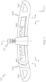
- the sling bar assembly 100 generally includes opposing sling bar members 120A and 120B that are slideably engaged with a lift engagement member 102.
- the sling bar member 120A is described as a "first sling bar member” and the sling bar member 120B is described as a "second sling bar member.”
- the lift engagement member 102 selectively couples the first and second sling bar members 120A, 120B to a subject support lift, as described in greater detail herein.
- the first sling bar member 120A includes a first sling hook 124A positioned at an outboard end of the first sling bar member 120A
- the second sling bar member 120B includes a second sling hook 124B positioned at an outboard end of the second sling bar member 120B.
- the first and second sling hooks 124A, 124B may selectively couple an accessory, such as a sling, a vest, or the like, to the sling bar assembly 100, such that a subject may be selectively coupled a subject support lift through the accessory and the sling bar assembly 100.
- the first sling bar member 120A and the second sling bar member 120B may be substantially the same, and the first sling bar member 120A generally includes a first bar body 122A and the first sling hook 124A.
- the second sling bar member 120B generally includes a second bar body 122B and the second sling hook 124B.
- the first and second sling hooks 124A, 124B are coupled to the first and second bar bodies 122A, 122B, respectively.
- the first and second sling hooks 124A, 124B are monolithic with the first and second bar bodies 122A, 122B, respectively.
- the first bar body 122A generally defines a first plurality of slots 136A extending in the lateral direction along the first bar body 122A.
- the second bar body 122B defines a second plurality of slots 136B extending in the lateral direction along the second bar body 122B.
- the first and the second plurality of slots 136A and 136B are generally oriented to face downward in the vertical direction and include crests 140A, 140B, respectively, extending downward in the vertical direction.
- the first plurality of slots 136A further includes individual slots 138A positioned between adjacent crests 140A
- the second plurality of slots 136B further includes individual slots 138B positioned between adjacent crests 140B.
- the first bar body 122A includes a first engagement member 144A extending outward from the first bar body 122A
- the second bar body 122B includes a second engagement member 144B extending outward from the second bar body 122B.
- first engagement member 144A extends outward from the first bar body 122A in the longitudinal direction toward the second bar body 122B
- second engagement member 144B extends outward from the second bar body 122B in the longitudinal direction toward to the first bar body 122A.
- the first and second engagement members 144A, 144B in embodiments not encompassed by the wording of the claims, have complementary shapes with the first and the second plurality of slots 136A, 136B.
- the first and second engagement members 144A, 144B each include generally cylindrical shapes, while the first and second plurality of slots 136A, 136B each include generally serpentine shape.
- the first engagement member 144A includes a cylindrical shape that is generally shaped and sized to fit at least partially within an individual slot 138B between adjacent crests 140B of the second sling bar member 120B.
- the second engagement member 144B also includes a cylindrical shape that is generally shaped and sized to fit at least partially within an individual slot 138A between adjacent crests 140A of the first sling bar member 120A. While the embodiment depicted in FIGS. 2A and 2B shows the first and second engagement members 144A, 144B having cylindrical shapes and the first and second plurality of slots 136A, 136B as having serpentine shapes, the first and second engagement members 144A, 144B and the first and second plurality of slots 136A, 136B may include any suitable complementary shapes that cooperate to selectively restrict lateral movement of the first bar body 122A and the second bar body 122B with respect to one another. For example, in other embodiments, the first and second engagement members 144A, 144B may form rectangular prisms or the like, while the first and second plurality of slots 136A, 136B may each include a rectangular wave shape or the like.
- first engagement member 144A of the first sling bar member 120A positioned within an individual slot 138B
- second engagement member 144B of the second sling bar member 120B positioned within an individual slot 138A
- movement of the first sling bar member 120A and the second sling bar member 120B with respect to one another in the lateral direction is restricted.
- engagement between adjacent crests 140B and the first engagement member 144A restricts lateral movement of the first sling bar member 120A with respect to the second sling bar member 120B.
- the first engagement member 144A is rigidly coupled to or monolithic with the first bar body 122A, such that restriction of movement of the first engagement member 144A with respect to the second sling bar member 120B restricts movement of first bar body 122A with respect to the second sling bar member 120B in the lateral direction.
- the second engagement member 144B is rigidly coupled to or may be monolithic with the second bar body 122B of the second sling bar member 120B, such that restriction of movement of the second engagement member 144B with respect to the first sling bar member 120A restricts movement of second bar body 122B with respect to the first sling bar member 120A in the lateral direction.
- the first bar body 122A defines a first cavity 130A extending inward into the first sling bar member 120A in the longitudinal direction.
- the second bar body 122B defines a second cavity 130B extending inward into the second sling bar member 120B in the longitudinal direction.
- the first cavity 130A defines the first plurality of slots 136A and a first guide portion 142A positioned below the first plurality of slots 136A.
- the second cavity 130B defines the second plurality of slots 136B and a second guide portion 142B positioned below the second plurality of slots 136B in the vertical direction.
- first and second cavities 130A, 130B may extend through the first sling bar member 120A and the second sling bar member 120B, respectively, in the longitudinal direction. In other embodiments, the first and second cavities 130A, 130B may extend only partially into the first sling bar member 120A and the second sling bar member 120B, respectively, in the longitudinal direction.
- first and second guide portions 142A, 142B each define a height hg evaluated in the vertical direction
- first and the second plurality of slots 136A, 136B each define a height hs evaluated in the vertical direction between the individual slots 138A, 138B and the crests 140A, 140B, respectively.
- the first and second engagement members 144A, 144B in embodiments, each define a height he evaluated in the vertical direction, and the height hg of the first and second guide portions 142A, 142B is greater than the height he of the first and second engagement members 144A, 144B.
- the first and second engagement members 144A, 144B may move in the lateral direction within the second and first guide portions 142B, 142A.
- the height hs of the first and second plurality of slots 136A, 136B corresponds to the height he of the first and second engagement members 144A, 144B, such that when the first and second engagement members 144A, 144B are positioned at least partially within the second and first plurality of slots 136B, 136A, respectively, the first and second engagement members 144A, 144B are retained within the second and first plurality of slots 136B, 136A.
- the first engagement member 144A is repositionable between the second plurality of slots 136B and the second guide portion 142B of the second sling bar member 120B.
- the second engagement member 144B is repositionable between the first plurality of slots 136A and the first guide portion 142A of the first sling bar member 120A.
- each of the first and second sling bar members 120A, 120B include the first and second engagement members 144A, 144B and the first and second plurality of slots 136A, 136B, respectively, it should be understood that in some embodiments, one of the first and second sling bar members 120A, 120B may include only an engagement member without including a plurality of slots, while the other of the first and second sling bar members 120A, 120B only includes the plurality of slots without including an engagement member.
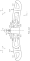
- the sling bar assembly 100 includes a lateral governor 150 engaged with and positioned between the first and second sling bar members 120A and 120B.
- the lateral governor 150 may be coupled to the lift engagement member 102 ( FIG. 1 ).
- the lateral governor 150 generally includes a pinion including a plurality of teeth 152 extending around a circumference of the lateral governor 150.
- the lateral governor 150 is rotatable, and in some embodiments, the lateral governor 150 is coupled to a motor or the like that induces the lateral governor 150 to rotate.
- the lateral governor 150 is not powered, and instead rotates as a result of movement of the first and second sling bar members 120A, 120B in the lateral direction.
- the first and second sling bar members 120A, 120B may include racks 146A and 146B, respectively, which are engaged with the lateral governor 150.
- the plurality of teeth 152 is engaged with the racks 146A, 146B, such that as the lateral governor 150 rotates, the rotation of the lateral governor 150 causes the first and second sling bar members 120A, 120B to move in opposite directions in the lateral direction.
- engagement between the racks 146A, 146B and the plurality of teeth 152 cause the lateral governor 150 to rotate.
- the lateral governor 150 generally permits movement of the first sling bar member 120A and the second sling bar member 120B in opposite directions in the lateral direction, while restricting movement of the first sling bar member 120A and the second sling bar member 120B in the same direction in the lateral direction. For example, a user may selectively move the first sling bar member 120A in the lateral direction ( e . g ., in the -Y-direction as depicted) with respect to the second sling bar member 120B.
- Engagement between the rack 146A of the first sling bar member 120A and the lateral governor 150 causes the lateral governor 150 to rotate ( e.g., in the clockwise direction as depicted) as the first sling bar member 120A moves in the -Y-direction as depicted.
- engagement between the lateral governor 150 and the rack 146B of the second sling bar member 120B causes the second sling bar member 120B to move in the +Y-direction as depicted.
- engagement between the rack 146A of the first sling bar member 120A and the lateral governor 150 causes the lateral governor 150 to rotate ( e.g., in the counter-clockwise direction as depicted) as the first sling bar member 120A moves in the +Y-direction as depicted.
- engagement between the lateral governor 150 and the rack 146B of the second sling bar member 120B causes the second sling bar member 120B to move in the -Y-direction as depicted.
- movement of either of the first or second sling bar member 120A, 120B in the lateral direction generally causes the lateral governor 150 to rotate, thereby causing the other of the first or second sling bar member 120A, 120B to move in an opposite direction in the lateral direction.
- the lateral governor 150 generally restricts movement of the first and second sling bar members 120A, 120B in the same direction in the lateral direction ( e .
- first sling hook 124A and the second sling hook 124B are spaced apart from the lift engagement member 102 ( FIG. 1 ) by the same distance such that a subject coupled to the sling bar assembly 100 through the first and second sling hook 124A, 124B is generally centered below the lift engagement member 102. Accordingly, by restricting movement of the first and second sling bar members 120A in the same direction in the lateral direction, the lateral governor 150 assists in ensuring that the first and second sling hook 124A, 124B are spaced apart from the lift engagement member 102 ( FIG. 1 ) by the same distance in the lateral direction.
- the lateral governor 150 may allow some rotation of the first sling bar member 120A and/or the second sling bar member 120B about the X-axis, as depicted, so as to allow the first and second sling bar members 120A, 120B to be repositioned between a locked position and an unlocked position, as described in greater detail herein.
- teeth of the plurality of teeth 152 may be generally smaller than teeth of the racks 146A, 146B, such that the first and second sling bar members 120A, 120B may rotate about the X-axis with respect to the lateral governor 150.
- the lateral governor 150 may include a conical or frustroconical shape that permits rotation of the first sling bar member 120A and/or the second sling bar member 120B about the X-axis with respect to the lateral governor 150.
- the racks 146A, 146B are depicted as being on a top surface of the first and second sling bar members 120A, 120B, in other embodiments, the racks 146A, 146B may be on other surfaces of the first and second sling bar members 120A, 120B, such as a lateral surface or a bottom surface of the first and second sling bar members 120A, 120B.
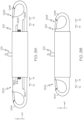
- FIGS. 4A-4C a front view of the sling bar assembly 100 not encompassed by the wording of the claims, being repositioned between a locked position and an unlocked position to expand the sling bar assembly 100 in the lateral direction. More particularly, by repositioning the first and second engagement members 144A, 144B between different slots 136B and 136A, respectively, a distance evaluated between the first sling hook 124A and the second sling hook 124B may be selectively adjusted.
- the sling bar assembly 100 is depicted in a locked position in which the first engagement member 144A of the first sling bar member 120A is positioned within the second plurality of slots 136B of the second sling bar member 120B, and the second engagement member 144B of the second sling bar member 120B is positioned within the first plurality of slots 136A of the first sling bar member 120A.
- the outboard ends of the first and second sling bar members 120A, 120B are moved upward in the vertical direction (i.e., in the +Z-direction as depicted), rotating the first and second sling bar members 120A, 120B about the X-axis with respect to the lift engagement member 102.
- the first engagement member 144A moves from the second plurality of slots 136B to the second guide portion 142B of the second sling bar member 120B.
- the second engagement member 144B moves from the first plurality of slots 136A to the first guide portion 142A of the first sling bar member 120A.
- the first sling bar member 120A and the second sling bar member 120B are movable with respect to one another in the lateral direction, such that the first sling hook 124A and the second sling hook 124B may be moved inboard toward, or outboard from the lift engagement member 102.
- the first sling bar member 120A and the second sling bar member 120B may be repositioned from the unlocked position into the locked position. More particularly, the first engagement member 144A is repositioned into the second plurality of slots 136B of the second sling bar member 120B. Similarly, the second engagement member 144B is repositioned into the first plurality of slots 136A of the first sling bar member 120A. In the example shown in FIGS.
- the first and second sling hooks 124A, 124B of the first and second sling bar members 120A, 120B are moved outboard in the lateral direction (i.e., in direction 12 as depicted) by repositioning the first and second engagement members 144A, 144B between individual slots 138B and 138A respectively.
- the first and second sling hooks 124A, 124B of the first and second sling bar members 120A, 120B may be moved inboard in the lateral direction ( i.e., in direction 14 as depicted) by repositioning the first and second engagement members 144A, 144B between individual slots 138B and 138A respectively. In this way, a distance between the first and second sling hooks 124A, 124B may be selectively adjusted in the lateral direction.
- the lateral span of the sling bar assembly 100 may be adjusted to accommodate different sized subjects and/or different sized accessories. For example, comparatively larger subjects may be wider in the lateral direction, and sling bar assemblies that are too narrow in the lateral direction may cause accessories to pinch or impinge the subject when coupled to a sling bar assembly. By contrast, comparatively smaller subjects may be narrower in the lateral direction, and sling bar assemblies that are too wide in the lateral direction may cause accessories to extend outward from the subject when coupled to a sling bar assembly, which may make the sling bar assembly difficult to manipulate and move between locations when transporting the subject.
- the sling bar assembly 100 may accommodate different sized subjects, thereby reducing the need for care facilities to stock and maintain multiple sizes of sling bar assemblies.
- the first and second plurality of slots 136A, 136B may include any suitable number and size of slots extending in the lateral direction, allowing for any level of lateral adjustment of the sling bar assembly 100.
- first and second plurality of slots 136A, 136B are oriented to face downward in the vertical direction. Because the first and second plurality of slots 136A, 136B are oriented to face downward in the vertical direction, the first and second plurality of slots 136A, 136B may be biased into engagement with the first and second engagement members 144A, 144B, for example as a result of gravity.
- the sling bar assembly 100 is biased into the locked position, such that the first sling bar member 120A and the second sling bar member 120B are generally not movable with respect to one another in the lateral direction unless actively moved into the unlocked position.
- the sling bar assembly 100 includes the opposing sling bar members 120A, 120B slidably engaged with the lift engagement member 102. Furthermore, like the embodiment described above, the first sling bar member 120A defines the first cavity 130A extending in the lateral direction, and the second sling bar member defines the second cavity 130B extending in the lateral direction. Like the embodiments described above and depicted in FIGS.
- the first sling bar member 120A includes the first sling hook 124A positioned at the outboard end of the first sling bar member 120A
- the second sling bar member 120B includes the second sling hook 124B positioned at the outboard end of the second sling bar member 120B.
- the first sling bar member 120A includes the rack 146A
- the second sling bar member 120B includes the rack 146B.
- the first and second cavities 130A, 130B do not include the slots 136A, 136B ( FIG. 2A ), and the first and second cavities 130A, 130B are formed as grooves extending in the lateral direction.
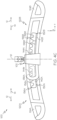
- the sling bar assembly 100 includes a sling bar frame 160 positioned between and engaged with the first and second sling bar members 120A, 120B..
- the sling bar frame 160 is coupled to the lift engagement member 102.
- the sling bar frame 160 may be coupled to the lift engagement member 102.
- the lift engagement member 102 is monolithic with the sling bar frame 160.
- the lateral governor 150 is coupled to the sling bar frame 160 and comprises the pinion positioned between and engaged with the racks 146A, 146B of the opposing sling bar members 120A, 120B.
- the sling bar frame 160 includes engagement members 144 extending outward from the sling bar frame 160.
- a biasing member 167 is engaged with the sling bar frame 160.
- the biasing member 167 is also engaged with one or both of the sling bar members 120A, 120B and biases at least one of the sling bar members 120A, 120B inboard toward the lift engagement member 102.
- the biasing member 167 may include a tension spring, a compression spring, a torsion spring, or the like.
- separate engagement members 144 may be coupled to sling bar frame 160 at different heights.
- two of the engagement members 144 are coupled to the sling bar frame 160 at an upper height
- three of the engagement members 144 are coupled to the sling bar frame 160 at a lower height that is below the upper height.
- the cavity 130A of the first sling bar member 120A is an upper cavity 130A
- the first sling bar member 120A further defines a lower cavity 130A' positioned below the upper cavity 130A in the vertical direction.
- the cavity 130B of the second sling bar member 120B is an upper cavity 130B, and the second sling bar member 120B further defines a lower cavity 130B' positioned below the upper cavity 130B in the vertical direction.
- the engagement members 144 at the upper height may be engaged with the upper cavities 130A, 130B, while the engagement members 144 at the lower height may be engaged with the lower cavities 130A', 130B'.
- force applied to the engagement members 144 through the first and second sling bar members 120A, 120B may be distributed, as compared to sling bar members including a single cavity.
- FIGS. 7A and 7B an enlarged top view and side view of the engagement of an engagement member 144 with the first sling bar member 120A are schematically depicted, respectively. While reference is made herein to the first sling bar member 120A, it should be understood that engagement members 144 may be similarly engaged with the second sling bar member 120B. Similarly, while reference is made herein to the upper cavity 130A, it should be understood that engagement members 144 may be similarly engaged with the lower cavity 130A' and the upper and lower cavities 130B, 130B'. Furthermore, while a single engagement member 144 is depicted in FIGS. 7A and 7B , it should be understood that each of the engagement members 144 may operate in the same manner.
- the engagement members 144 include rollers 145 positioned within the upper cavity 130A, and include a flange 143 that retains the roller 145 on the engagement member 144.
- the roller 145 is operable to rotate and can include one or more bearings that allow the roller 145 to rotate.
- the position of the engagement members 144 are generally fixed on the sling bar frame 160, and through engagement between the engagement members 144 and the first and second sling bar members 120A, 120B are movable with respect to the engagement members 144 and the sling bar frame 160 in the lateral direction.
- FIG. 8 a top view of the sling bar assembly 100 including the sling bar frame 160 is schematically depicted.
- ones of the engagement members 144 are engaged with the first sling bar member 120A, and other of the engagement members 144 are engaged with the second sling bar member 120B.
- one or all of the engagement members 144 may be simultaneously engaged with both the first sling bar member 120A and the second sling bar member 120B.
- the first sling hook 124A is offset from the first sling bar member 120A in the longitudinal direction and the second sling hook 124B is offset from the second sling bar member 120B in the longitudinal direction.
- the first sling bar member 120A and the second sling bar member 120B are spaced apart from one another in the longitudinal direction to allow the first sling bar member 120A and the second sling bar member 120B to move with respect to one another and the sling bar frame 160 in the lateral direction.
- the first sling hook 124A and the second sling hook 124B may be aligned with a centerline 16 bisecting the sling bar assembly 100 in the longitudinal direction.
- force applied to the sling bar assembly 100 such as may be applied by a subject positioned in a sling coupled to the sling bar assembly 100, may be evenly distributed, thereby reducing the tendency of the sling bar assembly 100 to rotate about the vertical direction.
- FIGS. 9A and 9B a side view of the sling bar assembly 100 in an expanded position and a retracted position are schematically depicted, respectively.
- the first and second sling bar members 120A, 120B are movable with respect to one another in the lateral direction.
- the first and second sling bar members 120A, 120B can be moved inboard (i.e., in direction 14) toward the lift engagement member 102 and outboard ( i.e., in direction 12) away from the lift engagement member 102.
- the lateral governor 150 FIG.
- first and second sling hooks 124A, 124B are generally maintained at the same distance from the lift engagement member 102 in the lateral direction.
- the first sling bar member 120A and the second sling bar member 120B are freely movable in the lateral direction.
- the size of the subject may apply force to the sling bar assembly 100 inducing the first and second sling bar members 124A, 124B to move outboard ( i.e., in direction 12 as depicted).
- the size of the subject may apply force to the sling bar assembly 100 inducing the first and second sling bar members 124A, 124B to move inboard ( i.e., in direction 14 as depicted).
- the first and second sling bar members 124A, 124B may freely move in the lateral direction to be appropriately positioned for different sized subjects.
- forces associated with the subject's weight may be directed through the sling bar assembly 100 to the lift engagement member 102 (and accordingly the lift device) through the engagement of the engagement members 144 ( FIG. 8 ) and the cavities 130A, 130A', 130B, 130B'.
- forces applied to the lateral governor 150 ( FIG. 8 ) as a result of the subject's weight may be minimized, thereby allowing the lateral governor 150 to rotate freely thereby allowing the first and second sling bar members 124A, 124B to move in the lateral direction.
- the sling bar assembly 100 includes the first sling bar member 120A and the second sling bar member 120B. Further, the first sling bar member 120A includes the rack 146A and the second sling bar member 120B includes the rack 146B, with the racks 146A, 146B engaged with the lateral governor 150.
- the sling bar frame 160 defines cavities 130', 130", and 130′′′ which are spaced apart from one another in the lateral direction. In some embodiments, such as the embodiment depicted in FIG. 10 , the sling bar frame 160 extends around the first sling bar member 120A and the second sling bar member 120B.
- one of the first sling bar member 120A and second sling bar member 120B includes the engagement member 144 that is positionable within the cavities 130', 130", and 130′′′. More particularly, in the embodiment depicted in FIG. 10 , the engagement member 144 includes a detent that is selectively positioned at least partially within one of the cavities 130', 130", or 130"'.
- the engagement member 144 is coupled to one of the first sling bar member 120A and the second sling bar member 120B, such that when the engagement member 144 is selectively positioned within one of the cavities 130', 130", or 130"', movement of the one of the first sling bar member 120A or the second sling bar member 120B with respect to the sling bar frame 160 is restricted. Similar to the embodiments described above, through engagement with the lateral governor 150, movement of the first sling bar member 120A and the second sling bar member 120B with respect to one another is restricted.
- a user may depress the engagement member 144 to unlock the first sling bar member 120A and the second sling bar member 120B, such that the first sling bar member 120A and the second sling bar member 120B are movable with respect to one another. Because the first sling bar member 120A and the second sling bar member 120B are selectively lockable with respect to one another with a single engagement member 144, a user can selectively lock and unlock the first and second sling bar members 120A, 120B with a single hand. While in the embodiment depicted in FIG. 10 , the sling bar assembly 100 includes a rectangular prism shape, it should be understood that in embodiments, the components of the sling bar assembly 100 can include any suitable shape, such as a cylindrical shape, a triangular prism shape, or the like.
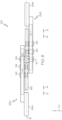
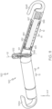
- the sling bar assembly 100 includes the lift engagement member 102 for selectively coupling to a subject support lift, and a sling bar member 120 extending in the lateral direction.
- the sling bar member 120 defines a channel 121 extending in the lateral direction.
- the channel 121 includes a generally circular shape and the sling bar member 120 includes a cylindrical shape surrounding the channel 121, however, it should be understood that the sling bar member 120 and the channel 121 may include any suitable shape.
- the sling bar member 120 may include a rectangular prism shape, a triangular prism, or the like.
- the sling bar assembly 100 includes a plunger 180 positioned at least partially within the channel 121 and slidably engaged with the sling bar member 120.
- the plunger 180 is movable within the channel 121 in the lateral direction.
- the sling hook 124B is positioned at an outboard end of the plunger 180.
- the sling hook 124B is coupled to the plunger 180.
- the sling hook 124B is monolithic with the plunger 180.
- the sling bar assembly 100 in embodiments not encompassed by the wording of the claims, further includes a biasing member 182 engaged with the plunger 180 and the sling bar member 120, where the biasing member 182 biases the plunger 180 in the inboard direction ( i.e., in direction 14 as depicted) toward the lift engagement member 102.
- the biasing member 182 may include a compressive spring that biases the plunger 180 in the inboard direction.
- the biasing member 182 may include a tension spring, a torsion spring, or the like.
- the sling bar assembly 100 further includes a sling bar stopper 186 defining an inner perimeter 187.
- the sling bar stopper 186 is positioned at the outboard end of the sling bar member 120, and generally acts to retain the plunger 180 within the sling bar member 120.
- the sling bar assembly 100 includes a plunger stopper 184 positioned at an end of the plunger 180 opposite the sling hook 124B.
- an outer perimeter 185 of the plunger stopper 184 is greater than the inner perimeter 187 of the sling bar stopper 186.
- the plunger stopper 184 and the sling bar stopper 186 act to capture the plunger 180 within the sling bar member 120. While in the view depicted in FIG. 11 , a plunger 180 is depicted with the sling hook 124B, it should be understood that in embodiments, the sling bar assembly 100 is symmetric about the lift engagement member 102 in the lateral direction and includes a similar plunger associated with the sling hook 124A.
- the plunger stopper 184 and/or the plunger 180 may include one or more bearings positioned between the plunger stopper 184 and/or the plunger 180 and the sling bar member 120.
- the bearings generally act to reduce friction between the plunger stopper 184 and/or the plunger 180 and the sling bar member 120.
- the weight of the subject may overcome or at least partially overcome the biasing member 182, and the plunger 180 and the sling hook 124B may move outboard in the lateral direction ( i.e., in direction 12 as depicted).
- the channel 121 extends outward in the lateral direction and downward in the vertical direction from the lift engagement member 102, such that the downward force associated with the weight of the subject may resolve into forces acting on the plunger in the lateral direction.
- the larger the subject the greater the force applied to the sling hooks 124A, 124B, and accordingly, the greater distance the plunger 180 (and accordingly the sling hooks 124A, 124B) moves outboard in the lateral direction.
- the sling bar assembly 100 includes the sling bar member 120, and includes multiple pairs of sling hooks spaced apart from one another.
- the sling bar assembly 100 includes a first pair of sling hooks 124A', 124B' that are spaced apart from the lift engagement member 102 by a first spacing distance.
- the sling bar assembly 100 further includes a second pair of sling hooks 124A", 124B" that are spaced apart from the lift engagement member 102 by a second spacing distance that is greater than the first spacing distance.
- the sling bar assembly 100 includes a third pair of sling hooks 124A"', 124B"' that are spaced apart from the lift engagement member 102 by a third spacing distance that is greater than the second spacing distance. While in the embodiment depicted in FIG. 12A , the sling bar assembly 100 includes three pairs of sling hooks (124A', 124B'; 124A", 124B"; 124A"', 124B'"), it should be understood that the sling bar assembly 100 may include any suitable number of pairs of sling hooks.
- each of the sling hooks 124A', 124B'; 124A", 124B"; 124A"', 124B'" may include latches that selectively enclose the sling hooks 124A', 124B'; 124A", 124B"; 124A′′′, 124B'".
- a user By including multiple pairs of sling hooks that are each spaced apart from the lift engagement member 102 by different distances, a user, such as a caregiver or the like, can selectively position a sling in different pairs of sling hooks to accommodate different sized subjects. It is generally desirable for a user to position a sling in corresponding pairs of sling hooks (i.e., 124A' with 124B'; 124A" with 124B"; 124A′′′ with 124B′′′) to ensure that the weight of the subject is balanced in the lateral direction.
- the sling bar assembly 100 includes a first pair of sensors 190A', 190B' that are associated with the first pair of sling hooks 124A', 124B', respectively.
- the sling bar assembly 100 in the embodiment depicted in FIG. 12A , includes a second pair of sensors 190A", 190B" that are associated with the second pair of sling hooks 124A", 124B", respectively.
- the sling bar assembly 100 includes a third pair of sensors 190A'", 190B′′′ that are associated with the third pair of sling hooks 124A"', 124B′′′.
- the first pair of sensors 190A', 190B', the second pair of sensors 190A", 190B", and the third pair of sensors 190A′′′, 190B′′′ are configured to detect the placement of an object (e . g ., a sling) in the first pair of sling hooks 124A', 124B', the second pair of sling hooks 124A", 124B", and the third pair of sling hooks 124A"', 124B"', and may include, for example and without limitation, a proximity sensor, a limit switch, or the like.
- the sling bar assembly 100 includes indicators associated with the pairs of sling hooks.
- the sling bar assembly 100 includes a first pair of indicators 192A', 192B' that are associated with the first pair of sling hooks 124A', 124B', respectively.
- the sling bar assembly 100 in the embodiment depicted in FIG. 12A , includes a second pair of indicators 192A", 192B" that are associated with the second pair of sling hooks 124A", 124B", respectively.
- the sling bar assembly 100 includes a third pair of indicators 192A"', 192B′′′ that are associated with the third pair of sling hooks 124A"', 124B′′′.
- the first pair of indicators 192A', 192B', the second pair of indicators 192A", 192B", and the third pair of indicators 192A"', 192B′′′ are configured to provide a visual indication, and may include, for example and without limitation, a light emitting diode (LED), or the like.
- LED light emitting diode
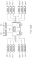
- the indicators 192A', 192A”, 192A′′′, 192B', 192B", 192B′′′ are communicatively coupled to an electronic control unit 400.
- the sensors 190A', 190A", 190A'", 190B', 190B", 190B′′′ are communicatively coupled to the electronic control unit 400.
- the electronic control unit 400 in embodiments, generally includes a processor 402 and a memory component 404.
- the memory component 404 may be configured as volatile and/or nonvolatile memory, and as such may include random access memory (including SRAM, DRAM, and/or other types of RAM), flash memory, secure digital (SD) memory, registers, compact discs (CD), digital versatile discs (DVD), bernoulli cartridges, and/or other types of non-transitory computer-readable mediums.
- the processor 402 may include any processing component operable to receive and execute instructions (such as from the memory component 404).
- the electronic control unit 400 is positioned on the sling bar assembly 100. In some embodiments, the electronic control unit 400 may be separate from and communicatively coupled to the sling bar assembly 100.
- the electronic control unit 400 is operable to selectively provide an indication via the indicators 192A', 192B', 192A", 192B", 192A"', 192B′′′ and/or prevent operation of a subject support lift 200, 300 ( FIGS. 13 , 14 ) unless a sling is detected in corresponding ones of the pairs of sling hooks 124A', 124B'; 124A", 124B"; and 124A′′′, 124B'".
- the electronic control unit 400 is configured to receive a signal from one of the pair of sensors 190A', 190B' associated with one of the first pair of sling hooks 124A', 124B' indicative of a sling positioned in the one of the first pair of sling hooks 124A', 124B'.
- the electronic control unit 400 further directs the indicator 192A', 192B' associated with the other of the first pair of sling hooks 124A', 124B' to engage.
- a user may position a loop of the sling in sling hook 124A'.
- the electronic control unit 400 receives a signal from the sensor 190A' associated with the sling hook 124A' indicative of the sling positioned in the sling hook 124A'.
- the electronic control unit 400 directs the indicator 192B' associated with the other of the pair of sling hooks ( e.g., sling hook 124B') to engage.
- the indicator 192B' can generally include a visual indicator, such as an LED.
- the sling bar assembly 100 may provide visual indications to a user to guide the user to couple the sling to corresponding and paired sling hooks. While the example above is described in reference to the first pair of sling hooks 124A', 124B', the first pair of sensors 190A', 190B', and the first pair of indicators 192A', 192B', it should be understood that the second pair of sling hooks 124A”, 124B", the second pair of sensors 190A”, 190B", and the second pair of indicators 192A", 192B", as well as the third pair of sling hooks 124A′′′, 124B′′′, the third pair of sensors 190A"', 190B"', and the third pair of indicators 192A"', 192B′′′ may operate in the same manner.
- the electronic control unit 400 may additionally or alternatively provide visual indications based at least in part on a subject profile associated with a subject.
- the electronic control unit 400 may store subject profiles in the memory component 404, and/or may communicatively coupled to a database including different subject profiles.
- the electronic control unit 400 may receive a subject profile including a desired placement of a sling on a particular pair of sling hooks 124A', 124B'; 124A", 124B"; or 124A"', 124B′′′.
- the electronic control unit 400 may direct the indicators 192A′′′, 192B′′′ to activate, providing a user an indication to utilize sling hooks 124A′′′ and 124B′′′ with a particular subject.
- the subject support lift 200 is an overhead lift.
- the subject support lift 200 generally includes a lift actuator 212 that is connected to a strap 214 that may be paid out or taken up by the lift actuator 212 in the vertical direction.
- the lift actuator 212 may include any suitable device for paying out and taking up the strap 214 in the vertical direction, such as an electric motor, a pneumatically powered device, a hydraulically powered device, or the like.
- a controller 218 is communicatively coupled to the lift actuator 212, and may be utilized by a user to control the operation of the lift actuator 212.
- the controller 218 may send signals to the lift actuator 212 causing the lift actuator 212 to pay out or take up the strap 214 in the vertical direction.
- the lift engagement member 102 is selectively coupled to and removable from the strap 214, such that the lift engagement member 102 may selectively couple the sling bar assembly 100 to the strap 214.
- the sling bar assembly 100 may be selectively adjustable in the lateral direction to accommodate a variety of different sized accessories.
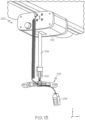
- FIG. 14 a perspective view of another subject support lift 300 suitable for use with the sling bar assembly 100 is schematically depicted.
- the subject support lift 600 is a mobile lift.
- the subject support lift 300 generally includes a mast 320 and a movable arm 310 movably coupled to the mast 320.
- the movable arm 310 may be operatively coupled to a lift actuator 312 that moves at least a portion of the movable arm 310 in the vertical direction.
- the lift engagement member 102 is selectively coupled to and removable from the strap 214, such that the lift engagement member 102 may selectively couple the sling bar assembly 100 to the movable arm 310.
- the mast 320 and the movable arm 310 are coupled to wheels or rollers 322, such that the subject support lift 300 may be moved between various locations.
- the electronic control unit 400 is communicatively coupled to the lift actuator 212 and/or the lift actuator 312.
- the operation of the lift actuator 212 and/or the lift actuator 312 may be directed, at least in part, by the electronic control unit 400.
- the electronic control unit 400 is configured to receive a signal from one of the first pair of sensors 190A', 190B' associated with one of the first pair of sling hooks 124A', 124B' indicative of a sling positioned in the one of the first pair of sling hooks 124A', 124B'.
- the electronic control unit 400 In response to receiving a signal from the sensor 190A' or 190B' associated with the other of the first pair of sling hooks 124A', 124B' indicative of a sling positioned in the other of the first pair of sling hooks 124A', 124B', the electronic control unit 400 sends a signal to the lift actuator 212 and/or the lift actuator 312 permitting the lift actuator 212 and/or the lift actuator 312 to move.
- the electronic control unit 400 In response to the lack of a signal from the sensor 190A' or 190B' associated with the other of the first pair of sling hooks 124A', 124B' indicative of a sling positioned in the other of the first pair of sling hooks 124A', 124B', the electronic control unit 400 a signal to the lift actuator 212 and/or the lift actuator 312 to restrict movement of the lift actuator 212 and/or 312.
- a user may position a loop of the sling in the sling hook 124A'.
- the electronic control unit 400 then receives a signal from the sensor 190A' associated with the sling hook 124A' indicative of the sling positioned in the sling hook 124A'. If the user positions another loop of the sling in the sling hook 124 B', the electronic control unit 400 then receives a signal from the sensor 190B' associated with the sling hook 124B' indicating that the sling is positioned in both the first pair of sling hooks 124A', 124B'.
- the electronic control unit 400 In response to receiving signals from both the first pair of sensors 190A', 190B' indicating that the sling is positioned in both the first pair of sling hooks 124A', 124B', the electronic control unit 400 sends a signal to the lift actuator 212 and/or the lift actuator 312 permitting the lift actuator 212 and/or the lift actuator 312 to move.
- the electronic control unit 400 does not receive a signal from both the first pair of sensors 190A', 190B' indicating that the sling is positioned in both the first pair of sling hooks 124A', 124B' (e.g., if the sling is only positioned in one of the first pair of sling hooks 124A', 124B'), the electronic control unit 400 directs the lift actuator 212 and/or the lift actuator 312 to restrict movement of the lift actuator 212 and/or the lift actuator 312.
- operation of the lift actuator 212 and/or the lift actuator 312 may be restricted unless the first pair of sensors 190A', 190B' confirms the appropriate connection of the sling in the first pair of sling hooks 124A', 124B'.
- the electronic control unit 400 may additionally or alternatively restrict operation of the lift actuator 212 and/or the lift actuator 312 based at least in part on a subject profile associated with a subject.
- the electronic control unit 400 may store subject profiles in the memory component 404, and/or may communicatively coupled to a database including different subject profiles.
- the electronic control unit 400 may receive a subject profile including a desired placement of a sling on a particular pair of sling hooks 124A', 124B'; 124A", 124B"; or 124A"', 124B′′′.
- the electronic control unit 400 may send a signal to the lift actuator 212 and/or the lift actuator 312 allowing the lift actuator 212 and/or the lift actuator 312 to move upon receiving a signal from the sensors 190A′′′, 190B′′′ indicating that the sling is positioned in the sling hooks 124A′′′ and 124B'".
- the electronic control unit 400 may direct the lift actuator 212 and/or the lift actuator 312 to restrict movement of the lift actuator 212 and/or the lift actuator 312 if signals are not received from the sensors 190A'", 190B′′′ indicating that the sling is positioned in the sling hooks 124A′′′ and 124B′′′.
- sling bar assemblies that include variable span in a lateral direction.
- sling bar assemblies generally include opposing sling bar members slidably engaged with a lift engagement member. Because the sling bar members are movable with respect to one another in the lateral direction, the span of the sling bar assembly may be adjusted to accommodate different sized accessories. By accommodating different sized accessories, sling bar assemblies described herein may reduce the need for care facilities to stock and maintain different sized sling bars and for caregivers to correlate appropriate sling bar assemblies with appropriate accessories.
- the sling bar members are selectively engaged with one another and are repositionable between a locked position, in which movement of the sling bar members with respect to one another is restricted in the lateral direction, and an unlocked position, in which the sling bar members are movable with respect to one another in the lateral direction.
- sling bar assemblies described herein include sling bar members with sling hooks engaged with biasing members.
- the biasing members allow the width of the sling bar assembly to expand upon the application of force to the sling bar assembly, such that the width of the sling bar increases as the size of a subject connected to the sling bar assembly increases.
- sling bar assemblies include multiple pairs of sling hooks positioned at different widths on the sling bar assembly. Sensors and/or indicators may be associated with different pairs of sling hooks to assist a user in positioning a sling in appropriate sling hooks for a particular subject.
Landscapes
- Health & Medical Sciences (AREA)
- Nursing (AREA)
- Life Sciences & Earth Sciences (AREA)
- Animal Behavior & Ethology (AREA)
- General Health & Medical Sciences (AREA)
- Public Health (AREA)
- Veterinary Medicine (AREA)
- Engineering & Computer Science (AREA)
- Mechanical Engineering (AREA)
- Load-Engaging Elements For Cranes (AREA)
Claims (13)
- Hebebügelanordnung (100), die Folgendes beinhaltet:Hebereingriffselement (102) zum selektiven Koppeln mit einem Personenlifter (200);einander entgegengesetzte Hebebügelelemente (120A, 120B), die verschiebbar mit dem Hebereingriffselement (102) in Eingriff sind, wobei die Hebebügelelemente (120A, 120B) jeweils einen Schlingenhaken (124A, 124B) beinhalten, der an einem außenliegenden Ende von jedem der Hebebügelelemente (120A, 120B) in einer Querrichtung positioniert ist, und wobei wenigstens eines der Hebebügelelemente (120A, 120B) einen Hohlraum (130A, 130B) definiert, der sich in das Hebebügelelement (120A, 120B) hinein erstreckt,einen Hebebügelrahmen (160), der mit dem Hebereingriffselement (102) gekoppelt ist and zwischen den einander entgegengesetzten Hebebügelelementen (120A, 120B) positioniert ist;ein Eingriffselement (144), das an dem Hebebügelrahmen (160) befestigt ist und sich davon nach außen erstreckt und das im Hohlraum (130A, 130B) positionierbar ist; undeinen Querregler (150), der zwischen bzw. mit den einander entgegengesetzten Hebebügelelementen (120A, 120B) positioniert und in Eingriff ist, wobei der Querregler (150) die einander entgegengesetzten Hebebügelelemente (120A, 120B) in einander entgegengesetzten Richtungen bewegt,wobei der Hohlraum (130A, 130B) eine Nut beinhaltet, die sich in der Querrichtung erstreckt, und das Eingriffselement (144) bewegbar mit der Nut in Eingriff ist.
- Hebebügelanordnung (100) nach Anspruch 1, wobei jedes der Hebebügelelemente (120A, 120B) eine Zahnstange (146A, 146B) beinhaltet, die sich in der Querrichtung erstreckt, und wobei der Querregler (150) ein Getrieberad beinhaltet, das zwischen bzw. mit den Zahnstangen der einander entgegengesetzten Hebebügelelemente (120A, 120B) positioniert und in Eingriff ist.
- Hebebügelanordnung (100) nach Anspruch 1, die ferner eine erste Vielzahl von Eingriffselementen, die sich vom Hebebügelrahmen nach außen erstrecken und mit dem Hohlraum (130A, 130B) von einem der Hebebügelelemente (120A, 120B) in Eingriff sind, und eine zweite Vielzahl von Eingriffselementen, die sich vom Hebebügelrahmen nach außen erstrecken und mit dem Hohlraum (130A, 130B) des anderen der Hebebügelelemente (120A, 120B) in Eingriff ist, beinhaltet.
- Hebebügelanordnung (100) nach einem der vorhergehenden Ansprüche, wobei der Hohlraum (130A, 130B), der sich in das wenigstens eine der Hebebügelelemente (120A, 120B) erstreckt, ein erster Hohlraum (130A, 130B) ist und das wenigstens eine der Hebebügelelemente (120A, 120B) einen zweiten Hohlraum (130A, 130B) beinhaltet, der in einer vertikalen Richtung unter dem ersten Hohlraum (130A, 130B) positioniert ist.
- Hebebügelanordnung (100) nach einem der vorhergehenden Ansprüche, die ferner ein Vorspannelement (167) beinhaltet, das mit wenigstens einem der einander entgegengesetzten Hebebügelelemente (120A, 120B) in Eingriff ist, wobei das Vorspannelement (167) das wenigstens eine der einander entgegengesetzten Hebebügelelemente (120A, 120B) in Richtung auf das Hebereingriffselement (102) vorspannt.
- Hebebügelanordnung (100) nach Anspruch 5, wobei die Hebebügelelemente (120A, 120B) zwischen einer verriegelten Stellung, in der die Bewegung der Hebebügelelemente (120A, 120B) in Bezug aufeinander in der Querrichtung beschränkt ist, und einer entriegelten Stellung, in der die Hebebügelelemente (120A, 120B) in Bezug aufeinander in der Querrichtung bewegbar sind, umstellbar sind.
- Hebebügelanordnung (100) nach einem der vorhergehenden Ansprüche, wobei das Eingriffselement (144) selektiv wenigstens teilweise im Hohlraum (130A, 130B) positioniert ist und bei wenigstens teilweiser Positionierung im Hohlraum (130A, 130B) die Bewegung der Hebebügelelemente (120A, 120B) in Bezug aufeinander in der Querrichtung beschränkt.
- Hebebügelanordnung (100) nach Anspruch 7, wobei das Eingriffselement (144) eine Arretierung beinhaltet, die selektiv wenigstens teilweise im Hohlraum (130A, 130B) positioniert ist.
- Hebebügelanordnung (100) nach einem der vorhergehenden Ansprüche, wobei eines der Hebebügelelemente (120A, 120B) eine Vielzahl von Schlitzen beinhaltet, die sich in der Querrichtung am Hebebügelelement (120A, 120B) entlang erstreckt, und das andere Hebebügelelement (120A, 120B) in einer verriegelten Stellung mit der Vielzahl von Schlitzen selektiv in Eingriff ist.
- Hebebügelanordnung (100) nach Anspruch 9, wobei der Hohlraum (130A, 130B) des Hebebügelelements (120A, 120B), der die Vielzahl von Schlitzen beinhaltet, einen Führungsteil definiert, der unter und beabstandet von der Vielzahl von Schlitzen positioniert ist, und in einer entriegelten Stellung das Eingriffselement (144) in dem Führungsteil positioniert ist.
- Hebebügelanordnung (100) nach Anspruch 10, wobei der Führungsteil des Hohlraums (130A, 130B) eine Höhe definiert, die größer als eine Höhe des Eingriffselements (144) ist.
- Hebebügelanordnung (100) nach einem der vorhergehenden Ansprüche, wobei das Eingriffselement (144) wenigstens teilweise in bzw. verschiebbar mit dem Hohlraum (130A, 130B) von einem der Hebebügelelemente (120A, 120B) positioniert und in Eingriff ist und mit dem anderen der Hebebügelelemente (120A, 120B) gekoppelt ist.
- Personenlifter (200), der Folgendes beinhaltet:einen Heberstellantrieb (212); undeine Hebebügelanordnung (100) nach einem der vorhergehenden Ansprüche, die selektiv mit bzw. von dem Heberstellantrieb (212) gekoppelt und abnehmbar ist.
Priority Applications (1)
| Application Number | Priority Date | Filing Date | Title |
|---|---|---|---|
| EP23188745.6A EP4241752B1 (de) | 2018-11-29 | 2019-11-19 | Einstellbare schlingenstangen für personenhebesysteme und verfahren zum betrieb davon |
Applications Claiming Priority (2)
| Application Number | Priority Date | Filing Date | Title |
|---|---|---|---|
| US201862772697P | 2018-11-29 | 2018-11-29 | |
| US201962856960P | 2019-06-04 | 2019-06-04 |
Related Child Applications (2)
| Application Number | Title | Priority Date | Filing Date |
|---|---|---|---|
| EP23188745.6A Division-Into EP4241752B1 (de) | 2018-11-29 | 2019-11-19 | Einstellbare schlingenstangen für personenhebesysteme und verfahren zum betrieb davon |
| EP23188745.6A Division EP4241752B1 (de) | 2018-11-29 | 2019-11-19 | Einstellbare schlingenstangen für personenhebesysteme und verfahren zum betrieb davon |
Publications (2)
| Publication Number | Publication Date |
|---|---|
| EP3659568A1 EP3659568A1 (de) | 2020-06-03 |
| EP3659568B1 true EP3659568B1 (de) | 2023-09-06 |
Family
ID=68847927
Family Applications (2)
| Application Number | Title | Priority Date | Filing Date |
|---|---|---|---|
| EP19210189.7A Active EP3659568B1 (de) | 2018-11-29 | 2019-11-19 | Verstellbare hebebügel für personenhebesysteme und verfahren zum betrieb davon |
| EP23188745.6A Active EP4241752B1 (de) | 2018-11-29 | 2019-11-19 | Einstellbare schlingenstangen für personenhebesysteme und verfahren zum betrieb davon |
Family Applications After (1)
| Application Number | Title | Priority Date | Filing Date |
|---|---|---|---|
| EP23188745.6A Active EP4241752B1 (de) | 2018-11-29 | 2019-11-19 | Einstellbare schlingenstangen für personenhebesysteme und verfahren zum betrieb davon |
Country Status (2)
| Country | Link |
|---|---|
| US (3) | US11259976B2 (de) |
| EP (2) | EP3659568B1 (de) |
Families Citing this family (7)
| Publication number | Priority date | Publication date | Assignee | Title |
|---|---|---|---|---|
| US11446193B2 (en) * | 2019-03-15 | 2022-09-20 | Liko Research & Development Ab | Person lift systems |
| USD989437S1 (en) * | 2021-04-06 | 2023-06-13 | Liko Research & Development Ab | Sling bar |
| USD989435S1 (en) * | 2021-04-06 | 2023-06-13 | Liko Research & Development Ab | Sling bar |
| USD1016302S1 (en) * | 2021-04-06 | 2024-02-27 | Liko Research & Development Ab | Sling bar |
| USD989436S1 (en) * | 2021-04-06 | 2023-06-13 | Liko Research & Development Ab | Sling bar |
| CN114180474A (zh) * | 2021-12-10 | 2022-03-15 | 延安大学 | 一种装配式建筑智能吊装设备及方法 |
| CN117361306A (zh) * | 2023-10-20 | 2024-01-09 | 中铁十局集团第五工程有限公司 | 一种钢结构施工用构件高效转运装置 |
Family Cites Families (12)
| Publication number | Priority date | Publication date | Assignee | Title |
|---|---|---|---|---|
| US4136903A (en) * | 1977-05-16 | 1979-01-30 | Roethler Kenneth W | Tire lifting apparatus |
| DE29505191U1 (de) | 1995-03-29 | 1995-06-08 | Glumann, Karl, 09127 Chemnitz | Lasttraverse für stationäre und mobile Hubgeräte zum Bewegen von stabförmigen Gegenständen |
| CA2217421C (en) * | 1997-10-03 | 2005-06-07 | Stephane Robert | A person lowering and raising winch assembly |
| US6289534B1 (en) * | 1998-07-31 | 2001-09-18 | Hill-Rom Services, Inc. | Patient lift |
| JP2001293045A (ja) * | 2000-04-11 | 2001-10-23 | Fuji Seisakusho:Kk | 介護用ホイストの吊りハンガ |
| EP1521565B1 (de) * | 2000-09-15 | 2011-01-12 | BHM Medical Inc. | Windevorrichtung zur lagerveränderung einer person von einer ersten vertikalen position in eine zweite vertikale position |
| GB2462058B (en) * | 2008-07-14 | 2012-08-08 | Joerns Healthcare Ltd | A spreader bar device |
| GB2462057A (en) * | 2008-07-14 | 2010-01-27 | Joerns Healthcare Ltd | Adjustable width support means for a patient handling hoist |
| CN202154910U (zh) | 2011-07-26 | 2012-03-07 | 黄亮才 | 一种卡背式输液架 |
| US9222498B2 (en) * | 2011-09-08 | 2015-12-29 | Arjohuntleigh Magog, Inc. | Lifting bar and lifting bar connector |
| US20140210223A1 (en) * | 2013-01-25 | 2014-07-31 | Julie Lamela | Spreader bar with integral scale |
| US9084709B2 (en) | 2013-03-14 | 2015-07-21 | Liko Research & Development Ab | Sling bar for patient lift slings |
-
2019
- 2019-11-19 EP EP19210189.7A patent/EP3659568B1/de active Active
- 2019-11-19 EP EP23188745.6A patent/EP4241752B1/de active Active
- 2019-11-26 US US16/695,518 patent/US11259976B2/en active Active
-
2022
- 2022-01-20 US US17/579,684 patent/US11918527B2/en active Active
-
2024
- 2024-01-30 US US18/427,055 patent/US12575986B2/en active Active
Also Published As
| Publication number | Publication date |
|---|---|
| EP3659568A1 (de) | 2020-06-03 |
| US20220133570A1 (en) | 2022-05-05 |
| US11918527B2 (en) | 2024-03-05 |
| EP4241752A3 (de) | 2023-11-22 |
| EP4241752A2 (de) | 2023-09-13 |
| US12575986B2 (en) | 2026-03-17 |
| EP4241752B1 (de) | 2026-04-08 |
| US20240164967A1 (en) | 2024-05-23 |
| US20200170864A1 (en) | 2020-06-04 |
| US11259976B2 (en) | 2022-03-01 |
Similar Documents
| Publication | Publication Date | Title |
|---|---|---|
| EP3659568B1 (de) | Verstellbare hebebügel für personenhebesysteme und verfahren zum betrieb davon | |
| US9975705B2 (en) | Article transport facility | |
| EP2109432B1 (de) | Patientenneupositionierungs- und gliedmassenausrichtungssystem | |
| EP2901997B1 (de) | Personenhubsystem | |
| US20120066831A1 (en) | Patient transfer apparatus | |
| US20200085657A1 (en) | Determining lifting events using sensors for person lifting apparatuses | |
| JP2009179464A (ja) | 縦向きコイル搬送用吊り具および吊り上げ搬送方法 | |
| CA2967871C (en) | Ceiling lift tilt management system | |
| EP3123109B1 (de) | Blockierbares kardan | |
| CN110709045B (zh) | 用于天花板患者升降机系统的接纳模块 | |
| US20250073509A1 (en) | Horizontal lifeline shuttle apparatus | |
| US20110219538A1 (en) | Support Means for a Patient Handling Hoist | |
| EP3427711B1 (de) | Hebebügel mit mehrfachbügelkompatibilität | |
| AU675995B2 (en) | Patient lifting device | |
| EP0084955B1 (de) | Trägheitsspule | |
| US7367547B2 (en) | Lifting device with release mechanism that moves with lifted object | |
| CN217838042U (zh) | 吊装用安全带的锁紧结构 | |
| EP3703535B1 (de) | Schutzschiene für ein bett, führungsgestell für eine schutzschiene und bett mit einer solchen schutzschiene | |
| GB2549749A (en) | Removable overhead hoist | |
| JP4492490B2 (ja) | 洗面化粧台 | |
| WO2009044178A1 (en) | A patient manoeuvring system | |
| HK40016039A (en) | Receiving module for ceiling patient lift system | |
| HK40016039B (en) | Receiving module for ceiling patient lift system | |
| HK1244662B (en) | Ceiling lift tilt management system | |
| HK1236609A1 (en) | A locking gimbal |
Legal Events
| Date | Code | Title | Description |
|---|---|---|---|
| PUAI | Public reference made under article 153(3) epc to a published international application that has entered the european phase |
Free format text: ORIGINAL CODE: 0009012 |
|
| STAA | Information on the status of an ep patent application or granted ep patent |
Free format text: STATUS: THE APPLICATION HAS BEEN PUBLISHED |
|
| AK | Designated contracting states |
Kind code of ref document: A1 Designated state(s): AL AT BE BG CH CY CZ DE DK EE ES FI FR GB GR HR HU IE IS IT LI LT LU LV MC MK MT NL NO PL PT RO RS SE SI SK SM TR |
|
| AX | Request for extension of the european patent |
Extension state: BA ME |
|
| STAA | Information on the status of an ep patent application or granted ep patent |
Free format text: STATUS: REQUEST FOR EXAMINATION WAS MADE |
|
| 17P | Request for examination filed |
Effective date: 20201203 |
|
| RBV | Designated contracting states (corrected) |
Designated state(s): AL AT BE BG CH CY CZ DE DK EE ES FI FR GB GR HR HU IE IS IT LI LT LU LV MC MK MT NL NO PL PT RO RS SE SI SK SM TR |
|
| STAA | Information on the status of an ep patent application or granted ep patent |
Free format text: STATUS: EXAMINATION IS IN PROGRESS |
|
| 17Q | First examination report despatched |
Effective date: 20220718 |
|
| GRAP | Despatch of communication of intention to grant a patent |
Free format text: ORIGINAL CODE: EPIDOSNIGR1 |
|
| STAA | Information on the status of an ep patent application or granted ep patent |
Free format text: STATUS: GRANT OF PATENT IS INTENDED |
|
| INTG | Intention to grant announced |
Effective date: 20230321 |
|
| GRAS | Grant fee paid |
Free format text: ORIGINAL CODE: EPIDOSNIGR3 |
|
| GRAA | (expected) grant |
Free format text: ORIGINAL CODE: 0009210 |
|
| STAA | Information on the status of an ep patent application or granted ep patent |
Free format text: STATUS: THE PATENT HAS BEEN GRANTED |
|
| AK | Designated contracting states |
Kind code of ref document: B1 Designated state(s): AL AT BE BG CH CY CZ DE DK EE ES FI FR GB GR HR HU IE IS IT LI LT LU LV MC MK MT NL NO PL PT RO RS SE SI SK SM TR |
|
| REG | Reference to a national code |
Ref country code: GB Ref legal event code: FG4D |
|
| REG | Reference to a national code |
Ref country code: CH Ref legal event code: EP |
|
| REG | Reference to a national code |
Ref country code: IE Ref legal event code: FG4D |
|
| REG | Reference to a national code |
Ref country code: DE Ref legal event code: R096 Ref document number: 602019036660 Country of ref document: DE |
|
| REG | Reference to a national code |
Ref country code: LT Ref legal event code: MG9D |
|
| REG | Reference to a national code |
Ref country code: NL Ref legal event code: MP Effective date: 20230906 |
|
| PG25 | Lapsed in a contracting state [announced via postgrant information from national office to epo] |
Ref country code: GR Free format text: LAPSE BECAUSE OF FAILURE TO SUBMIT A TRANSLATION OF THE DESCRIPTION OR TO PAY THE FEE WITHIN THE PRESCRIBED TIME-LIMIT Effective date: 20231207 |
|
| PG25 | Lapsed in a contracting state [announced via postgrant information from national office to epo] |
Ref country code: SE Free format text: LAPSE BECAUSE OF FAILURE TO SUBMIT A TRANSLATION OF THE DESCRIPTION OR TO PAY THE FEE WITHIN THE PRESCRIBED TIME-LIMIT Effective date: 20230906 Ref country code: RS Free format text: LAPSE BECAUSE OF FAILURE TO SUBMIT A TRANSLATION OF THE DESCRIPTION OR TO PAY THE FEE WITHIN THE PRESCRIBED TIME-LIMIT Effective date: 20230906 Ref country code: NO Free format text: LAPSE BECAUSE OF FAILURE TO SUBMIT A TRANSLATION OF THE DESCRIPTION OR TO PAY THE FEE WITHIN THE PRESCRIBED TIME-LIMIT Effective date: 20231206 Ref country code: LV Free format text: LAPSE BECAUSE OF FAILURE TO SUBMIT A TRANSLATION OF THE DESCRIPTION OR TO PAY THE FEE WITHIN THE PRESCRIBED TIME-LIMIT Effective date: 20230906 Ref country code: LT Free format text: LAPSE BECAUSE OF FAILURE TO SUBMIT A TRANSLATION OF THE DESCRIPTION OR TO PAY THE FEE WITHIN THE PRESCRIBED TIME-LIMIT Effective date: 20230906 Ref country code: HR Free format text: LAPSE BECAUSE OF FAILURE TO SUBMIT A TRANSLATION OF THE DESCRIPTION OR TO PAY THE FEE WITHIN THE PRESCRIBED TIME-LIMIT Effective date: 20230906 Ref country code: GR Free format text: LAPSE BECAUSE OF FAILURE TO SUBMIT A TRANSLATION OF THE DESCRIPTION OR TO PAY THE FEE WITHIN THE PRESCRIBED TIME-LIMIT Effective date: 20231207 Ref country code: FI Free format text: LAPSE BECAUSE OF FAILURE TO SUBMIT A TRANSLATION OF THE DESCRIPTION OR TO PAY THE FEE WITHIN THE PRESCRIBED TIME-LIMIT Effective date: 20230906 |
|
| REG | Reference to a national code |
Ref country code: AT Ref legal event code: MK05 Ref document number: 1607546 Country of ref document: AT Kind code of ref document: T Effective date: 20230906 |
|
| PG25 | Lapsed in a contracting state [announced via postgrant information from national office to epo] |
Ref country code: NL Free format text: LAPSE BECAUSE OF FAILURE TO SUBMIT A TRANSLATION OF THE DESCRIPTION OR TO PAY THE FEE WITHIN THE PRESCRIBED TIME-LIMIT Effective date: 20230906 |
|
| PG25 | Lapsed in a contracting state [announced via postgrant information from national office to epo] |
Ref country code: IS Free format text: LAPSE BECAUSE OF FAILURE TO SUBMIT A TRANSLATION OF THE DESCRIPTION OR TO PAY THE FEE WITHIN THE PRESCRIBED TIME-LIMIT Effective date: 20240106 |
|
| PG25 | Lapsed in a contracting state [announced via postgrant information from national office to epo] |
Ref country code: AT Free format text: LAPSE BECAUSE OF FAILURE TO SUBMIT A TRANSLATION OF THE DESCRIPTION OR TO PAY THE FEE WITHIN THE PRESCRIBED TIME-LIMIT Effective date: 20230906 |
|
| PG25 | Lapsed in a contracting state [announced via postgrant information from national office to epo] |
Ref country code: ES Free format text: LAPSE BECAUSE OF FAILURE TO SUBMIT A TRANSLATION OF THE DESCRIPTION OR TO PAY THE FEE WITHIN THE PRESCRIBED TIME-LIMIT Effective date: 20230906 |
|
| PG25 | Lapsed in a contracting state [announced via postgrant information from national office to epo] |
Ref country code: SM Free format text: LAPSE BECAUSE OF FAILURE TO SUBMIT A TRANSLATION OF THE DESCRIPTION OR TO PAY THE FEE WITHIN THE PRESCRIBED TIME-LIMIT Effective date: 20230906 Ref country code: RO Free format text: LAPSE BECAUSE OF FAILURE TO SUBMIT A TRANSLATION OF THE DESCRIPTION OR TO PAY THE FEE WITHIN THE PRESCRIBED TIME-LIMIT Effective date: 20230906 Ref country code: IS Free format text: LAPSE BECAUSE OF FAILURE TO SUBMIT A TRANSLATION OF THE DESCRIPTION OR TO PAY THE FEE WITHIN THE PRESCRIBED TIME-LIMIT Effective date: 20240106 Ref country code: ES Free format text: LAPSE BECAUSE OF FAILURE TO SUBMIT A TRANSLATION OF THE DESCRIPTION OR TO PAY THE FEE WITHIN THE PRESCRIBED TIME-LIMIT Effective date: 20230906 Ref country code: EE Free format text: LAPSE BECAUSE OF FAILURE TO SUBMIT A TRANSLATION OF THE DESCRIPTION OR TO PAY THE FEE WITHIN THE PRESCRIBED TIME-LIMIT Effective date: 20230906 Ref country code: CZ Free format text: LAPSE BECAUSE OF FAILURE TO SUBMIT A TRANSLATION OF THE DESCRIPTION OR TO PAY THE FEE WITHIN THE PRESCRIBED TIME-LIMIT Effective date: 20230906 Ref country code: AT Free format text: LAPSE BECAUSE OF FAILURE TO SUBMIT A TRANSLATION OF THE DESCRIPTION OR TO PAY THE FEE WITHIN THE PRESCRIBED TIME-LIMIT Effective date: 20230906 Ref country code: SK Free format text: LAPSE BECAUSE OF FAILURE TO SUBMIT A TRANSLATION OF THE DESCRIPTION OR TO PAY THE FEE WITHIN THE PRESCRIBED TIME-LIMIT Effective date: 20230906 Ref country code: PT Free format text: LAPSE BECAUSE OF FAILURE TO SUBMIT A TRANSLATION OF THE DESCRIPTION OR TO PAY THE FEE WITHIN THE PRESCRIBED TIME-LIMIT Effective date: 20240108 |
|
| PG25 | Lapsed in a contracting state [announced via postgrant information from national office to epo] |
Ref country code: PL Free format text: LAPSE BECAUSE OF FAILURE TO SUBMIT A TRANSLATION OF THE DESCRIPTION OR TO PAY THE FEE WITHIN THE PRESCRIBED TIME-LIMIT Effective date: 20230906 Ref country code: IT Free format text: LAPSE BECAUSE OF FAILURE TO SUBMIT A TRANSLATION OF THE DESCRIPTION OR TO PAY THE FEE WITHIN THE PRESCRIBED TIME-LIMIT Effective date: 20230906 |
|
| REG | Reference to a national code |
Ref country code: DE Ref legal event code: R097 Ref document number: 602019036660 Country of ref document: DE |
|
| REG | Reference to a national code |
Ref country code: CH Ref legal event code: PL |
|
| PG25 | Lapsed in a contracting state [announced via postgrant information from national office to epo] |
Ref country code: MC Free format text: LAPSE BECAUSE OF FAILURE TO SUBMIT A TRANSLATION OF THE DESCRIPTION OR TO PAY THE FEE WITHIN THE PRESCRIBED TIME-LIMIT Effective date: 20230906 |
|
| PG25 | Lapsed in a contracting state [announced via postgrant information from national office to epo] |
Ref country code: DK Free format text: LAPSE BECAUSE OF FAILURE TO SUBMIT A TRANSLATION OF THE DESCRIPTION OR TO PAY THE FEE WITHIN THE PRESCRIBED TIME-LIMIT Effective date: 20230906 |
|
| PLBE | No opposition filed within time limit |
Free format text: ORIGINAL CODE: 0009261 |
|
| STAA | Information on the status of an ep patent application or granted ep patent |
Free format text: STATUS: NO OPPOSITION FILED WITHIN TIME LIMIT |
|
| PG25 | Lapsed in a contracting state [announced via postgrant information from national office to epo] |
Ref country code: LU Free format text: LAPSE BECAUSE OF NON-PAYMENT OF DUE FEES Effective date: 20231119 |
|
| PG25 | Lapsed in a contracting state [announced via postgrant information from national office to epo] |
Ref country code: CH Free format text: LAPSE BECAUSE OF NON-PAYMENT OF DUE FEES Effective date: 20231130 |
|
| PG25 | Lapsed in a contracting state [announced via postgrant information from national office to epo] |
Ref country code: MC Free format text: LAPSE BECAUSE OF FAILURE TO SUBMIT A TRANSLATION OF THE DESCRIPTION OR TO PAY THE FEE WITHIN THE PRESCRIBED TIME-LIMIT Effective date: 20230906 Ref country code: LU Free format text: LAPSE BECAUSE OF NON-PAYMENT OF DUE FEES Effective date: 20231119 Ref country code: DK Free format text: LAPSE BECAUSE OF FAILURE TO SUBMIT A TRANSLATION OF THE DESCRIPTION OR TO PAY THE FEE WITHIN THE PRESCRIBED TIME-LIMIT Effective date: 20230906 Ref country code: CH Free format text: LAPSE BECAUSE OF NON-PAYMENT OF DUE FEES Effective date: 20231130 Ref country code: SI Free format text: LAPSE BECAUSE OF FAILURE TO SUBMIT A TRANSLATION OF THE DESCRIPTION OR TO PAY THE FEE WITHIN THE PRESCRIBED TIME-LIMIT Effective date: 20230906 |
|
| REG | Reference to a national code |
Ref country code: BE Ref legal event code: MM Effective date: 20231130 |
|
| 26N | No opposition filed |
Effective date: 20240607 |
|
| REG | Reference to a national code |
Ref country code: IE Ref legal event code: MM4A |
|
| PG25 | Lapsed in a contracting state [announced via postgrant information from national office to epo] |
Ref country code: IE Free format text: LAPSE BECAUSE OF NON-PAYMENT OF DUE FEES Effective date: 20231119 |
|
| PG25 | Lapsed in a contracting state [announced via postgrant information from national office to epo] |
Ref country code: BE Free format text: LAPSE BECAUSE OF NON-PAYMENT OF DUE FEES Effective date: 20231130 |
|
| PG25 | Lapsed in a contracting state [announced via postgrant information from national office to epo] |
Ref country code: IE Free format text: LAPSE BECAUSE OF NON-PAYMENT OF DUE FEES Effective date: 20231119 Ref country code: BE Free format text: LAPSE BECAUSE OF NON-PAYMENT OF DUE FEES Effective date: 20231130 |
|
| PG25 | Lapsed in a contracting state [announced via postgrant information from national office to epo] |
Ref country code: BG Free format text: LAPSE BECAUSE OF FAILURE TO SUBMIT A TRANSLATION OF THE DESCRIPTION OR TO PAY THE FEE WITHIN THE PRESCRIBED TIME-LIMIT Effective date: 20230906 |
|
| PG25 | Lapsed in a contracting state [announced via postgrant information from national office to epo] |
Ref country code: BG Free format text: LAPSE BECAUSE OF FAILURE TO SUBMIT A TRANSLATION OF THE DESCRIPTION OR TO PAY THE FEE WITHIN THE PRESCRIBED TIME-LIMIT Effective date: 20230906 |
|
| PG25 | Lapsed in a contracting state [announced via postgrant information from national office to epo] |
Ref country code: CY Free format text: LAPSE BECAUSE OF FAILURE TO SUBMIT A TRANSLATION OF THE DESCRIPTION OR TO PAY THE FEE WITHIN THE PRESCRIBED TIME-LIMIT; INVALID AB INITIO Effective date: 20191119 |
|
| PG25 | Lapsed in a contracting state [announced via postgrant information from national office to epo] |
Ref country code: HU Free format text: LAPSE BECAUSE OF FAILURE TO SUBMIT A TRANSLATION OF THE DESCRIPTION OR TO PAY THE FEE WITHIN THE PRESCRIBED TIME-LIMIT; INVALID AB INITIO Effective date: 20191119 |
|
| PG25 | Lapsed in a contracting state [announced via postgrant information from national office to epo] |
Ref country code: TR Free format text: LAPSE BECAUSE OF FAILURE TO SUBMIT A TRANSLATION OF THE DESCRIPTION OR TO PAY THE FEE WITHIN THE PRESCRIBED TIME-LIMIT Effective date: 20230906 |
|
| PGFP | Annual fee paid to national office [announced via postgrant information from national office to epo] |
Ref country code: DE Payment date: 20251022 Year of fee payment: 7 |
|
| PGFP | Annual fee paid to national office [announced via postgrant information from national office to epo] |
Ref country code: GB Payment date: 20251022 Year of fee payment: 7 |
|
| PGFP | Annual fee paid to national office [announced via postgrant information from national office to epo] |
Ref country code: FR Payment date: 20251022 Year of fee payment: 7 |