EP3659649B1 - Joint de seringue - Google Patents
Joint de seringue Download PDFInfo
- Publication number
- EP3659649B1 EP3659649B1 EP18843196.9A EP18843196A EP3659649B1 EP 3659649 B1 EP3659649 B1 EP 3659649B1 EP 18843196 A EP18843196 A EP 18843196A EP 3659649 B1 EP3659649 B1 EP 3659649B1
- Authority
- EP
- European Patent Office
- Prior art keywords
- face
- ring
- barrel
- trimmed
- gasket
- Prior art date
- Legal status (The legal status is an assumption and is not a legal conclusion. Google has not performed a legal analysis and makes no representation as to the accuracy of the status listed.)
- Active
Links
Images




Classifications
-
- A—HUMAN NECESSITIES
- A61—MEDICAL OR VETERINARY SCIENCE; HYGIENE
- A61M—DEVICES FOR INTRODUCING MEDIA INTO, OR ONTO, THE BODY; DEVICES FOR TRANSDUCING BODY MEDIA OR FOR TAKING MEDIA FROM THE BODY; DEVICES FOR PRODUCING OR ENDING SLEEP OR STUPOR
- A61M5/00—Devices for bringing media into the body in a subcutaneous, intra-vascular or intramuscular way; Accessories therefor, e.g. filling or cleaning devices, arm-rests
- A61M5/178—Syringes
- A61M5/31—Details
- A61M5/315—Pistons; Piston-rods; Guiding, blocking or restricting the movement of the rod or piston; Appliances on the rod for facilitating dosing ; Dosing mechanisms
- A61M5/31511—Piston or piston-rod constructions, e.g. connection of piston with piston-rod
- A61M5/31513—Piston constructions to improve sealing or sliding
-
- A—HUMAN NECESSITIES
- A61—MEDICAL OR VETERINARY SCIENCE; HYGIENE
- A61M—DEVICES FOR INTRODUCING MEDIA INTO, OR ONTO, THE BODY; DEVICES FOR TRANSDUCING BODY MEDIA OR FOR TAKING MEDIA FROM THE BODY; DEVICES FOR PRODUCING OR ENDING SLEEP OR STUPOR
- A61M5/00—Devices for bringing media into the body in a subcutaneous, intra-vascular or intramuscular way; Accessories therefor, e.g. filling or cleaning devices, arm-rests
- A61M5/178—Syringes
- A61M5/28—Syringe ampoules or carpules, i.e. ampoules or carpules provided with a needle
-
- B—PERFORMING OPERATIONS; TRANSPORTING
- B29—WORKING OF PLASTICS; WORKING OF SUBSTANCES IN A PLASTIC STATE IN GENERAL
- B29C—SHAPING OR JOINING OF PLASTICS; SHAPING OF MATERIAL IN A PLASTIC STATE, NOT OTHERWISE PROVIDED FOR; AFTER-TREATMENT OF THE SHAPED PRODUCTS, e.g. REPAIRING
- B29C39/00—Shaping by casting, i.e. introducing the moulding material into a mould or between confining surfaces without significant moulding pressure; Apparatus therefor
- B29C39/02—Shaping by casting, i.e. introducing the moulding material into a mould or between confining surfaces without significant moulding pressure; Apparatus therefor for making articles of definite length, i.e. discrete articles
- B29C39/10—Shaping by casting, i.e. introducing the moulding material into a mould or between confining surfaces without significant moulding pressure; Apparatus therefor for making articles of definite length, i.e. discrete articles incorporating preformed parts or layers, e.g. casting around inserts or for coating articles
-
- B—PERFORMING OPERATIONS; TRANSPORTING
- B29—WORKING OF PLASTICS; WORKING OF SUBSTANCES IN A PLASTIC STATE IN GENERAL
- B29C—SHAPING OR JOINING OF PLASTICS; SHAPING OF MATERIAL IN A PLASTIC STATE, NOT OTHERWISE PROVIDED FOR; AFTER-TREATMENT OF THE SHAPED PRODUCTS, e.g. REPAIRING
- B29C51/00—Shaping by thermoforming, i.e. shaping sheets or sheet like preforms after heating, e.g. shaping sheets in matched moulds or by deep-drawing; Apparatus therefor
- B29C51/12—Shaping by thermoforming, i.e. shaping sheets or sheet like preforms after heating, e.g. shaping sheets in matched moulds or by deep-drawing; Apparatus therefor of articles having inserts or reinforcements
-
- A—HUMAN NECESSITIES
- A61—MEDICAL OR VETERINARY SCIENCE; HYGIENE
- A61M—DEVICES FOR INTRODUCING MEDIA INTO, OR ONTO, THE BODY; DEVICES FOR TRANSDUCING BODY MEDIA OR FOR TAKING MEDIA FROM THE BODY; DEVICES FOR PRODUCING OR ENDING SLEEP OR STUPOR
- A61M2205/00—General characteristics of the apparatus
- A61M2205/02—General characteristics of the apparatus characterised by a particular materials
-
- A—HUMAN NECESSITIES
- A61—MEDICAL OR VETERINARY SCIENCE; HYGIENE
- A61M—DEVICES FOR INTRODUCING MEDIA INTO, OR ONTO, THE BODY; DEVICES FOR TRANSDUCING BODY MEDIA OR FOR TAKING MEDIA FROM THE BODY; DEVICES FOR PRODUCING OR ENDING SLEEP OR STUPOR
- A61M2205/00—General characteristics of the apparatus
- A61M2205/02—General characteristics of the apparatus characterised by a particular materials
- A61M2205/0238—General characteristics of the apparatus characterised by a particular materials the material being a coating or protective layer
-
- A—HUMAN NECESSITIES
- A61—MEDICAL OR VETERINARY SCIENCE; HYGIENE
- A61M—DEVICES FOR INTRODUCING MEDIA INTO, OR ONTO, THE BODY; DEVICES FOR TRANSDUCING BODY MEDIA OR FOR TAKING MEDIA FROM THE BODY; DEVICES FOR PRODUCING OR ENDING SLEEP OR STUPOR
- A61M2205/00—General characteristics of the apparatus
- A61M2205/02—General characteristics of the apparatus characterised by a particular materials
- A61M2205/025—Materials providing resistance against corrosion
-
- A—HUMAN NECESSITIES
- A61—MEDICAL OR VETERINARY SCIENCE; HYGIENE
- A61M—DEVICES FOR INTRODUCING MEDIA INTO, OR ONTO, THE BODY; DEVICES FOR TRANSDUCING BODY MEDIA OR FOR TAKING MEDIA FROM THE BODY; DEVICES FOR PRODUCING OR ENDING SLEEP OR STUPOR
- A61M2207/00—Methods of manufacture, assembly or production
-
- A—HUMAN NECESSITIES
- A61—MEDICAL OR VETERINARY SCIENCE; HYGIENE
- A61M—DEVICES FOR INTRODUCING MEDIA INTO, OR ONTO, THE BODY; DEVICES FOR TRANSDUCING BODY MEDIA OR FOR TAKING MEDIA FROM THE BODY; DEVICES FOR PRODUCING OR ENDING SLEEP OR STUPOR
- A61M5/00—Devices for bringing media into the body in a subcutaneous, intra-vascular or intramuscular way; Accessories therefor, e.g. filling or cleaning devices, arm-rests
- A61M5/178—Syringes
- A61M5/31—Details
- A61M5/315—Pistons; Piston-rods; Guiding, blocking or restricting the movement of the rod or piston; Appliances on the rod for facilitating dosing ; Dosing mechanisms
- A61M5/31511—Piston or piston-rod constructions, e.g. connection of piston with piston-rod
-
- B—PERFORMING OPERATIONS; TRANSPORTING
- B29—WORKING OF PLASTICS; WORKING OF SUBSTANCES IN A PLASTIC STATE IN GENERAL
- B29K—INDEXING SCHEME ASSOCIATED WITH SUBCLASSES B29B, B29C OR B29D, RELATING TO MOULDING MATERIALS OR TO MATERIALS FOR MOULDS, REINFORCEMENTS, FILLERS OR PREFORMED PARTS, e.g. INSERTS
- B29K2021/00—Use of unspecified rubbers as moulding material
- B29K2021/003—Thermoplastic elastomers
-
- B—PERFORMING OPERATIONS; TRANSPORTING
- B29—WORKING OF PLASTICS; WORKING OF SUBSTANCES IN A PLASTIC STATE IN GENERAL
- B29K—INDEXING SCHEME ASSOCIATED WITH SUBCLASSES B29B, B29C OR B29D, RELATING TO MOULDING MATERIALS OR TO MATERIALS FOR MOULDS, REINFORCEMENTS, FILLERS OR PREFORMED PARTS, e.g. INSERTS
- B29K2995/00—Properties of moulding materials, reinforcements, fillers, preformed parts or moulds
- B29K2995/0037—Other properties
- B29K2995/0058—Inert to chemical degradation
-
- B—PERFORMING OPERATIONS; TRANSPORTING
- B29—WORKING OF PLASTICS; WORKING OF SUBSTANCES IN A PLASTIC STATE IN GENERAL
- B29L—INDEXING SCHEME ASSOCIATED WITH SUBCLASS B29C, RELATING TO PARTICULAR ARTICLES
- B29L2031/00—Other particular articles
- B29L2031/26—Sealing devices, e.g. packaging for pistons or pipe joints
- B29L2031/265—Packings, Gaskets
Definitions
- the present invention relates to a gasket for a syringe, and particularly relates to a gasket for a prefilled syringe.
- Gaskets that slide inside a barrel by being pushed with a plunger rod while maintaining liquid tightness so as to prevent leakage of a liquid such as a medical fluid inside the barrel are used for syringes (injectors).
- Such gaskets are made of an elastic material such as rubber or a thermoplastic elastomer in order to maintain liquid tightness by being in close contact, without a gap, with the inner circumferential face of the barrel of syringes.
- prefilled syringes that have been filled with a liquid in advance are becoming widely used in order to prevent mix-ups of medical fluids and the like.
- Patent Literatures 1 and 2 disclose syringe gaskets whose top face and side circumferential face are coated with an inert film made of a resin that is inert to a liquid. Such gaskets are molded by placing an inert film and a rubber sheet in an overlapping manner in a mold and then performing heating compression or the like. After the molding, the rubber sheet is punched to obtain gaskets. According to Patent Literature 2, punching is performed while causing a pulling force to act on the rubber sheet (which may be referred to as an "undercut method"). Accordingly, the rubber on the cut face is prevented from bulging out from the outer circumference of the side circumferential face of the gasket.
- WO 2016/120565 A1 discloses a plunger-stopper comprising a cylindrical body having a front axial side closed by a front wall, said hollow cylindrical body comprising an outer surface provided with at least one secondary sealing profile, said front wall comprising a front axial outer surface provided with a coating, advantageously an ethylene tetrafluoroethylene film, said front wall comprising along the radially outer edge thereof a primary sealing profile, said front wall and said hollow cylindrical body being made of different materials, said hollow cylindrical body being overmolded on said front wall, said front axial outer surface of said front wall comprising a deformation profile arranged inside said primary sealing profile of said front wall, said deformation profile being suitable for deforming radially to facilitate insertion and/or sliding of said plunger-stopper in a syringe body.
- JP2001190667A and WO 2002/022192 Aldisclose sliding members made of rubber elastic material, which slide in close contact with an inner wall of a syringe outer cylinder.
- the gasket may be difficult to control the pulling force that is to act on the rubber sheet in the undercut method. Since the gasket returns to its original shape due to the internal stress of the rubber when the pulling force is canceled after the cutting, according to the undercut method, variations or errors may appear in the dimensions of the gasket around the cut portion. If variations or errors appear in the outer circumferential dimensions of the gasket, the gasket cannot be in close contact with the inner wall of the syringe with a uniform force thereagainst. Accordingly, the gasket may wobble inside the barrel, and the liquid may come into contact with a portion of the gasket not coated with the inert film, and the liquid tightness may be impaired.
- a first aspect of the present invention is directed to a syringe gasket configured to be coupled to a plunger rod of a syringe, and to slide inside a barrel of the syringe by being pushed with the plunger rod, including: a first member configured to be inserted into the barrel, and to be in contact with a liquid accommodated in the barrel; and a second member configured to be inserted into the barrel, and to be coupled to the plunger rod, the second member being connected to the first member.
- the first member includes: a top face configured to be in contact with the liquid; and a first side circumferential face that is continuous with an outer circumferential edge of the top face, and configured to face an inner circumferential face of the barrel.
- the first side circumferential face has, at an end portion thereof close to the second member, a ring-like trimmed face, and the ring-like trimmed face is recessed to be closer to the inner side in a radial direction than the portion of the first side circumferential face other than the ring-like trimmed face.
- An inert film is laminated on the top face and the portion of the first side circumferential face other than the ring-like trimmed face.
- the second member includes: a second side circumferential face configured to face the inner circumferential face of the barrel; and a ring-like protruding portion that extends in a circumferential direction on the second side circumferential face, projects outward in the radial direction from the second side circumferential face, and is configured to be contact with the inner circumferential face of the barrel when the second member is inserted into the barrel.
- the ring-like protruding portion at least partially covers the ring-like trimmed face from the outer side in the radial direction.
- a second aspect of the present invention is directed to the syringe gasket according to the first aspect, wherein the ring-like protruding portion covers the entire ring-like trimmed face from the outer side in the radial direction.
- a third aspect of the present invention is directed to the syringe gasket according to the first or second aspect, wherein the first member and the second member are made of a rubber or a thermoplastic elastomer.
- a fourth aspect of the present invention is directed to the syringe gasket according to any one of the first to third aspects, wherein the top face has a convex portion projecting toward a space in which the liquid is accommodated in the barrel.
- a fifth aspect of the present invention is directed to the syringe gasket according to any one of the first to fourth aspects, wherein the top face has, at an outer circumferential portion thereof, an inclined face that is inclined toward the second member as being closer to the outer side in the radial direction.
- a sixth aspect of the present invention is directed to the syringe gasket according to the fifth aspect, wherein an angle formed by the portion of the first side circumferential face other than the ring-like trimmed face and the inclined face is 90° or more and 110° or less.
- a seventh aspect of the present invention is directed to the syringe gasket according to any one of the first to sixth aspects, wherein the inert film is made of a material selected from the group consisting of tetrafluoroethylene-ethylene copolymer, modified tetrafluoroethylene-ethylene copolymer, and polychlorotrifluoroethylene.
- An eighth aspect of the present invention is directed to a method for producing a syringe gasket configured to be coupled to a plunger rod of a syringe, and to slide inside a barrel of the syringe by being pushed with the plunger rod, including the following steps:
- the step (6) includes pouring the second material such that the second material is in contact with the ring-like trimmed face of the first member, and a ring-like protruding portion that at least partially covers the ring-like trimmed face is formed.
- the present invention provides a syringe gasket that is liquid-resistant and excellent in terms of liquid tightness.
- FIG. 1 is a cross-sectional view of a syringe 4 using a syringe gasket (hereinafter, may simply be referred to as a "gasket") 1 according to this embodiment
- FIG. 2 is a cross-sectional view of the gasket 1.
- the gasket 1 is attached to the front end of a plunger rod (hereinafter, may simply be referred to as a "rod") 41 of the syringe 4, and inserted into a barrel 40 of the syringe 4 together with the rod 41.
- a plunger rod hereinafter, may simply be referred to as a "rod
- a space (hereinafter, referred to as an "accommodation space") C1 defined by the inner circumferential face of the barrel 40 and the gasket 1, and the accommodation space C1 is filled with a liquid.
- the gasket 1 slides inside the barrel 40 in accordance with the rod 41 being pushed, and is used to push the liquid inside the accommodation space C1 toward an injector needle 42.
- the liquid herein is typically a medical fluid.
- the syringe 4 according to this embodiment is a prefilled syringe, and the accommodation space C1 accommodates the liquid in advance before use of the syringe 4.
- the gasket 1 includes a first member 1a and a second member 1b, and the members 1a and 1b are inseparably connected to each other in one piece.
- the first member 1a has a top face 10, and the top face 10 is in contact with the liquid inside the accommodation space C1.
- the second member 1b is connected to a bottom portion 14 of the first member 1a opposite to the top face 10 in the direction in which a central axis A1 extends.
- the central axis A1 refers to a central axis direction of the barrel 40 substantially in the shape of a cylinder as shown in FIGS. 1 and 2 , and the direction in which the central axis A1 extends matches the direction in which the gasket 1 slides inside the barrel 40.
- the position of the central axis A1 may be referred to when describing not only the syringe 4 but also the structure of each portion in the gasket 1, but, in this case, the state in which the gasket 1 is inserted in the barrel 40 is taken as a reference. Furthermore, also when describing the positional relationship between the barrel 40 and the gasket 1, the state in which the gasket 1 is inserted in the barrel 40 is taken as a reference.
- the inner circumferential face of the barrel 40 is configured such that its cross-section that is orthogonal to the central axis A1 is substantially in the shape of a circle, and the gasket 1, and the first member 1a and the second member 1b constituting the gasket 1 are configured such that their cross-sections that are orthogonal to the central axis A1 are substantially in the shape of a circle.
- the first member 1a and the second member 1b are made of an elastic material, and typically made of rubber or a thermoplastic elastomer. More specifically, the first member 1a and the second member 1b may be made of butyl rubber, isoprene rubber, butadiene rubber, halogenated butyl rubber, ethylene-propylene terpolymer, silicone rubber, or the like, but there is no limitation to these examples. The first member 1a and the second member 1b may be made of the same material or may be made of different materials.
- the first member 1a has a first side circumferential face 11 that is continuous with the outer circumferential edge of the top face 10 and faces the inner circumferential face of the barrel 40.
- the first side circumferential face 11 has, at an end portion thereof close to the second member 1b in the direction in which the central axis A1 extends, a ring-like trimmed face 12.
- the ring-like trimmed face 12 is recessed to be further inward in the radial direction than the other portions in the first side circumferential face 11, and cannot be seen in plan view from the side of the top face 10 of the first member 1a.
- the radial direction herein is defined using the central axis A1 as a reference, unless otherwise described.
- An inert film 13 that does not react with the liquid is laminated on the top face 10 and the first side circumferential face 11. Note that the inert film 13 is not laminated on the ring-like trimmed face 12. Accordingly, the entire ring-like trimmed face 12 is covered by the second member 1b from the outer side in the radial direction as described later, but there is no inert film 13 between the ring-like trimmed face 12 and the second member 1b.
- an inert region a region in which the inert film 13 is laminated is referred to as an inert region.
- the portion of the first side circumferential face 11 other than the ring-like trimmed face 12 is in contact with the inner circumferential face of the barrel 40 or faces the inner circumferential face of the barrel 40 with a slight gap interposed therebetween. Accordingly, the liquid is substantially confined within the accommodation space C1 between the barrel 40 and the top face 10, so that the liquid is in contact with the top face 10, but is not in contact with or is barely in contact with the other portions of the gasket 1.
- the liquid is mainly in contact with only the top face 10 coated with the inert film 13, and thus a situation is prevented in which particles of components of a material of which the first member 1a and the second member 1b are made elute into the liquid inside the accommodation space C1, thereby contaminating or deteriorating the liquid.
- the gasket 1 has high liquid resistance, and has high medical fluid resistance in the case where the liquid is a medical fluid.
- the portion not being in contact with the liquid or barely being in contact with the liquid is coated with the inert film 13.
- the reason for this is that, in the case of coating only the top face 10, there may be a region not coated with the inert film 13 near the outer circumferential edge of the top face 10 due to production errors.
- the top face 10 can be reliably coated with the inert film 13 by laminating the inert film 13 not only on the top face 10 but also on a region of the first side circumferential face 11 near the outer circumferential edge of the top face 10.
- the inert film 13 is typically made of a fluorine resin or an olefin-based resin. More specifically, the inert film 13 is made of tetrafluoroethylene-ethylene copolymer (ETFE), a modified tetrafluoroethylene-ethylene copolymer, polytetrafluoroethylene (PTFE), polychlorotrifluoroethylene (PCTFE), or the like, but there is no limitation to these materials.
- ETFE tetrafluoroethylene-ethylene copolymer
- PTFE polytetrafluoroethylene
- PCTFE polychlorotrifluoroethylene
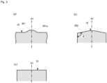
- the shape of the top face 10 is not limited to that shown in FIG. 2 .
- the top face 10 may have a convex portion 301 projecting toward the accommodation space C1 of the liquid.
- the convex portion 301 may have an inclined face 301a that is inclined from the position of the central axis A1 toward the second member 1b as it approaches the outer side in the radial direction, and the portion of the top face 10 other than the inclined face 301a may be a flat face that is orthogonal to the central axis A1.
- the top face 10 may have a plurality of steps of inclined faces. Also, as shown in FIG.
- the top face 10 may have a shape in which the circumferential portion of the top face 10 has an inclined face 302 that is inclined toward the second member 1b as it approaches the outer side in the radial direction (the circumferential portion of the top face 10 is chamfered along the circumferential direction).
- the portion of the top face 10 other than the inclined face 302 may be a flat face that is orthogonal to the central axis A1.
- an angle ⁇ formed by the first side circumferential face 11 other than the ring-like trimmed face 12 and the inclined face 302 is preferably 90° or more and 110° or less.
- the entire top face 10 may be a flat face that is orthogonal to the central axis A1.
- the second member 1b has a second side circumferential face 21 that faces the inner circumferential face of the barrel 40, and two ring-like protruding portions 20a and 20b that stand upright on the second side circumferential face 21.
- the second side circumferential face 21 faces the inner circumferential face of the barrel 40 substantially in parallel.
- the ring-like protruding portions 20a and 20b are arranged on the second side circumferential face 21 with a predetermined gap interposed therebetween in the direction in which the central axis A1 extends, and the ring-like protruding portion 20a is arranged closer to the accommodation space C1 than the ring-like protruding portion 20b is.
- the first side circumferential face 11 of the first member 1a and the second side circumferential face 21 of the second member 1b are at substantially the same distance from the central axis A1. Accordingly, the ring-like protruding portions 20a and 20b protrude, in the radial direction, past not only the second side circumferential face 21 but also the first side circumferential face 11. Furthermore, the ring-like protruding portions 20a and 20b have substantially the same height using the second side circumferential face 21 as a reference.
- the ring-like protruding portions 20a and 20b both come into contact with the inner circumferential face of the barrel 40, and, at this time, the ring-like protruding portions 20a and 20b are in close contact, without a gap, with the inner circumferential face of the barrel 40 due to the elasticity of the material thereof.
- the ring-like protruding portions 20a and 20b extend on the second side circumferential face 21 throughout the circumferential direction.
- the circumferential direction herein is defined using the central axis A1 as a reference.
- the liquid inside the accommodation space C1 is tightly confined with the ring-like protruding portion 20a that is in close contact with the barrel 40, and does not leak out of the gasket 1.
- the ring-like protruding portions 20a and 20b support the gasket 1 such that the central axis of the gasket 1 matches the central axis A1 of the barrel 40. Accordingly, in this embodiment, the central axis of the gasket 1 does not deviate or shift from the central axis A1 of the barrel 40, and, furthermore, the liquid tightness of the barrel 40 is maintained.
- the ring-like protruding portion 20a covers the entire ring-like trimmed face 12 from the outer side in the radial direction.
- the ring-like protruding portion 20a can firmly support the bottom portion 14 of the first member 1a.
- the second member 1b having the ring-like protruding portions 20a and 20b that are in close contact with the inner circumferential face of the barrel 40 but also the first member 1a can be firmly supported with the ring-like protruding portion 20a inside the barrel 40, and thus the gasket can reliably slide inside the barrel 40.
- the central axis of the first member 1a is not likely to deviate from the central axis A1 of the barrel 40, and thus the liquid tightness is further improved.
- the ring-like protruding portion 20a does not necessarily have to cover the entire ring-like trimmed face 12 from the outer side in the radial direction.
- the ring-like protruding portion 20a is preferably arranged near the ring-like trimmed face 12, and preferably at least partially covers the ring-like trimmed face 12.
- the second member 1b has, at an end portion thereof opposite to the first member 1a in the central axis A1, a coupling portion 22 that is to be coupled with the rod 41.
- the coupling portion 22 has, at an end portion of the second member 1b opposite to the first member 1a, an opening C2, and the opening C2 receives the front end of the rod 41.
- the coupling portion 22 of this embodiment is formed in the shape of a female screw, and the front end of the rod 41 is formed in the shape of a male screw.
- the above-described configuration in which the ring-like protruding portion 20a at least partially covers the ring-like trimmed face 12 is preferable.
- the second member 1b is connected to the first member 1a so as to cover the ring-like trimmed face 12 from the outer side in the radial direction.
- the ring-like trimmed face 12 is in contact with the inner wall of the second member 1b, and does not appear on the surface of the gasket 1. That is to say, the ring-like trimmed face 12 is not in contact with the inner circumferential face of the barrel 40, and thus even when variations appear in the outer circumferential dimensions of the ring-like trimmed face 12, the variations do not affect the performance of the gasket 1.
- variations in the outer circumferential dimensions of the ring-like trimmed face 12 due to using the undercut method do not cause a problem.
- the ring-like protruding portion 20a is formed on the second side circumferential face 21 so as to at least partially cover the ring-like trimmed face 12.
- the ring-like trimmed face 12 is recessed to be further inward in the radial direction than the portion of the first side circumferential face 11 other than the ring-like trimmed face 12, and thus the portion that covers the ring-like trimmed face 12 is thicker than in the case where the ring-like trimmed face 12 is not recessed (the ring-like trimmed face is not formed).
- the strength of the ring-like protruding portion 20a increases, and the gasket 1 is more firmly supported, and thus the central axis of the gasket 1 is more unlikely to deviate.
- the inert film 13 is not laminated on the ring-like trimmed face 12, the first member 1a and the second member 1b are connected to each other in a state in which the ring-like trimmed face 12 and the second member 1b are in direct contact with each other. Accordingly, the inert film 13 is between the ring-like trimmed face 12 and the second member 1b, peeling off of the second member 1b from the ring-like trimmed face 12 is prevented without reducing the connection force between the ring-like trimmed face 12 and the second member 1b. That is to say, the connection between the first member 1a and the second member 1b can be made more firm.
- a method for producing the syringe gasket 1 according to this embodiment will be described with reference to FIGS. 4 to 6 .
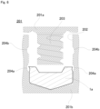
- a first mold 101 and a second mold 201 are prepared.
- FIG. 4 is a schematic cross-sectional view illustrating a step of molding the first member 1a.
- a first material 111 for forming the first member 1a and an inert film 112 for forming the inert film 13 are placed in the first mold 101 for molding the first member 1a.
- the first material 111 is made of rubber or a thermoplastic elastomer, and, in this embodiment, is in the shape of a sheet. If the first member 1a is made of rubber, the first material 111 may be a material obtained by mixing a vulcanizing agent and the like as appropriate with an unvulcanized rubber.
- the first mold 101 includes an upper mold 101a and a lower mold 101b.
- a cavity 102 is formed in the face of the lower mold 101b facing the upper mold 101a, and the portion of the face other than the cavity 102 is substantially flat.
- the cavity 102 has a shape substantially corresponding to the external shape of the first member 1a, and its cross-section that is orthogonal to the depth direction is in the shape of a circle. That is to say, the cavity 102 is substantially in the shape of a solid cylinder, and, in this embodiment, the deepest portion in the shape of an inverted cone corresponds to the shape of the top face 10.
- a convex portion 103 in the shape of a circular truncated cone is formed on the face of the upper mold 101a facing the lower mold 101b, and the portion of the face other than the convex portion 103 is substantially flat.
- the convex portion 103 of the upper mold 101a is used in combination with the cavity 102 of the lower mold 101b.
- FIG. 4 shows only one cavity 102, but, in this embodiment, it is assumed that a plurality of cavities 102 arranged at predetermined intervals are formed in the lower mold 101b. Also, it is assumed that a plurality of convex portions 103 arranged at predetermined intervals so as to correspond to the cavities 102 of the lower mold 101b are formed on the upper mold 101a.
- the inert film 112 and the first material 111 are placed on the first mold 101 in an overlapping manner in the order of the inert film 112 and the first material 111 from the deeper side of the cavities 102.
- the upper mold 101a and the lower mold 101b are closed to perform compression molding while applying heat to the inert film 112 and the first material 111.
- the central axis of the convex portion 103 of the upper mold 101a is positioned at the central axis of the cavity 102 of the lower mold 101b.
- the inert film 112 and the first material 111 are held between the upper mold 101a and the lower mold 101b and positioned within the cavity 102. If compression molding is performed in this state, the inert film 112 and the first material 111 are softened to fill the entire cavity 102 and molded into the shape of the cavity 102, and the inert film 112 and the first material 111 are joined together.
- the molding method is not limited to compression molding and other known methods may be used as appropriate.
- the first sheet 113 is a sheet in which a plurality of first members 1a are coupled to each other at predetermined intervals corresponding to the above-described intervals of the cavities 102 of the lower mold 101b, and the first members 1a are coupled to each other at the bottom portions 14 thereof via coupling portions 115.
- the coupling portions 115 are formed by being held between the substantially flat portions of the face of the lower mold 101b facing the upper mold 101a excluding the cavities 102 and the substantially flat portions of the face of the upper mold 101a facing the lower mold 101b excluding the convex portions 103.
- concave portions 114 each substantially in the shape of a circular truncated cone corresponding to the convex portions 103 are formed in the first sheet 113 on the upper mold 101a side.
- the first sheet 113 is cut to separate a plurality of first members 1a from the first sheet 113.
- positioning rods 104 are respectively fitted to the concave portions 114 formed in the first sheet 113, and the first sheet 113 is fixed in this state.
- the positioning rods 104 are designed such that, when fitted to the concave portions 114 formed in the first sheet 113, a substantially uniform pulling force acts on the coupling portions 115 of the first sheet 113.
- the pulling force acts on the coupling portions 115 so as to pull the first members 1a included in the first sheet 113 outward in the radial direction, and the first members 1a spread out to be slightly flat.
- each first member 1a included in the first sheet 113 mainly the portion corresponding to the bottom portion 14 spreads more, and the spread amount becomes smaller toward the top face 10.
- the portion corresponding to the first side circumferential face 11 is substantially in the shape of a circular truncated cone that spreads outward from the top face 10 toward the bottom portion 14. Accordingly, if the first sheet 113 is punched in this state from the inert film 112 side using a punching blade 105, even considering variations in production, the punching blade 105 is not likely to come into contact with the portion of the first member 1a that is to be formed into the inert film 13. Thus, the first member 1a can be produced without damaging the inert film 13.
- the second mold 201 includes an upper mold 201a and a lower mold 201b.
- a cavity 202 is formed in the face of the lower mold 201b facing the upper mold 201a, and the portion of the face other than the cavity 202 is substantially flat.
- the cavity 202 has a shape substantially corresponding to the external shape of the gasket 1, and its cross-section that is orthogonal to the depth direction is in the shape of a circle. That is to say, the cavity 202 is substantially in the shape of a solid cylinder, and, in this embodiment, the deepest portion is in a shape corresponding to the external shape of the first member 1a arranged upside down.
- a convex portion 203 in the shape of a circular truncated cone is formed on the face of the upper mold 201a facing the lower mold 201b, and the portion of the face other than the convex portion 203 is substantially flat.
- the convex portion 203 of the upper mold 201a is used in combination with the cavity 202 of the lower mold 201b.
- FIG. 6 shows only one cavity 202, but, in this embodiment, it is assumed that a plurality of cavities 202 arranged at predetermined intervals are formed in the lower mold 201b. Also, it is assumed that a plurality of convex portions 203 arranged at predetermined intervals so as to correspond to the cavities 202 of the lower mold 201b are formed on the upper mold 201a.
- the first member 1a is placed in the cavity 202 of the second mold 201 such that the top face 10 is positioned on the deeper side.
- the portion of the cavity 202 on which the first member 1a is placed is formed such that the top face 10 and the first side circumferential face 11 are substantially fitted thereto.
- the upper mold 201a and the lower mold 201b are closed, and the second material is poured onto the first member 1a inside the cavity 202. Accordingly, a second member 1b connected to the bottom portion 14 of the first member 1a, that is, a gasket 1 is molded.
- the second material is made of rubber or a thermoplastic elastomer. If the second member 1b is made of rubber, the second material may be a material obtained by mixing a vulcanizing agent and the like as appropriate with an unvulcanized rubber, and vulcanization is performed simultaneously with the step of molding the second material.
- Ring-like concave portions 204a and 204b corresponding to the outer circumferential shapes of the ring-like protruding portions 20a and 20b are formed in the face constituting the side face of the cavity 202 in the lower mold 201b.
- the ring-like concave portion 204a is arranged on the deeper side relative to the ring-like concave portion 204b.
- the ring-like concave portion 204a is positioned so as to face the ring-like trimmed face 12 at the same depth as the ring-like trimmed face 12 when the first member 1a is placed at the deepest portion of the cavity 202.
- a second member in which the second material is in contact with the ring-like trimmed face 12 and the ring-like protruding portion 20a at least partially covers the ring-like trimmed face 12 is molded.
- the gasket 1 according to this embodiment is obtained by removing the gasket 1 from the second mold 201.
- the first sheet 113 including the first member 1a is first molded using the first mold 101, after which the first member 1a is cut through punching from the first sheet 113. It is possible to produce the first member 1a without damaging the inert film 112 of the first sheet 113 by causing a pulling force to act on a predetermined position on the first sheet 113 when cutting the gasket 1.
- the ring-like protruding portions 20a and 20b of the second member 1b are formed so as to cover the ring-like trimmed face 12 of the first member 1a. That is to say, the ring-like protruding portions 20a and 20b are molded using the molds, after which they are not punched as in the case of molding the first member 1a, and thus variations or errors that may appear in the outer circumferential dimensions of the ring-like protruding portions 20a and 20b can be reduced.
- the level of precision of the outer circumferential dimensions of the ring-like protruding portions 20a and 20b is improved, and the ring-like protruding portions 20a and 20b can support, with a uniform force along the circumferential direction, the gasket 1 inside the barrel 40, so that the central axis of the gasket 1 can be prevented from be deviating or shifting, and high liquid tightness can be realized.
- the coupling portion 22 may be in the shape of a male screw.
- the front end of the plunger rod 41 is in the shape of a female screw.
- the method for coupling the gasket 1 and the rod 41 is not limited to a screwing method.
- it may be a snapping method in which the front end of the rod 41 is inserted and snapped into the opening C2 of the coupling portion 22.
- the gasket 1 according to the foregoing embodiment can be produced using a method other than the production method according to the foregoing embodiment.
- the ring-like trimmed face 12 does not necessarily have to be a cut face formed using the undercut method.
- an example of the undercut method was described in the process of the foregoing embodiment, but the specific methods are not limited thereto, and a method not using the positioning rod 104 may be employed.
- the number thereof may be one, or may be three or more. However, it is important that the ring-like protruding portion 20a that is the closest to the first member 1a at least partially covers the ring-like trimmed face 12.
Landscapes
- Health & Medical Sciences (AREA)
- Engineering & Computer Science (AREA)
- Hematology (AREA)
- Anesthesiology (AREA)
- Biomedical Technology (AREA)
- Heart & Thoracic Surgery (AREA)
- Vascular Medicine (AREA)
- Life Sciences & Earth Sciences (AREA)
- Animal Behavior & Ethology (AREA)
- General Health & Medical Sciences (AREA)
- Public Health (AREA)
- Veterinary Medicine (AREA)
- Mechanical Engineering (AREA)
- Infusion, Injection, And Reservoir Apparatuses (AREA)
Claims (8)
- Joint de seringue (1) configuré pour être couplé à une tige de piston (41) d'une seringue (4) et pour coulisser à l'intérieur d'un cylindre (40) de la seringue (4) en étant poussé avec la tige de piston (41) comprenant :un premier élément (1a) configuré pour être inséré dans le cylindre (40) etpour être en contact avec un liquide logé dans le cylindre (40) ; etun second élément (1b) configuré pour être inséré dans le cylindre (40) etpour être couplé à la tige de piston (41), le second élément (1b) étant connecté au premier élément (1a),dans lequel le premier élément (1a) comprend :une face de partie supérieure (10) configurée pour être en contact avec le liquide ; etune première face circonférentielle de côté (11) qui est continue avec un bord circonférentiel externe de la face de partie supérieure (10) etconfigurée pour faire face à une face circonférentielle interne du cylindre (40),la première face circonférentielle de côté (11) a, à une de ses parties d'extrémité proche du second élément (1b), une face restreinte de type anneau (12) et la face restreinte de type anneau (12) est en retrait pour être plus proche du coté interne dans une direction radiale que la partie de la première face circonférentielle (11) différente de la face restreinte de type anneau (12),un film inerte (13) est laminé sur la face de partie supérieure (10) et la partie de première face circonférentielle de côté (11) différente de la face restreinte de type anneau (12),le second élément (1b) comprend :une seconde face circonférentielle de côté (21) configurée pour faire face à la face circonférentielle interne du cylindre (40) ; etune partie faisant saillie de type anneau (20a) qui s'étend dans une direction circonférentielle suer la seconde face circonférentielle de côté (21), se projette vers l'extérieur dans la direction radiale de la seconde face circonférentielle (21) et est configurée pour être en contact avec la face circonférentielle interne du cylindre (40) quand le second élément (1b) est inséré dans le cylindre (1b) etla partie faisant saillie de type anneau (20a) recouvre au moins partiellement la face restreinte de type anneau (12) à partir du côté externe dans la direction radiale.
- Joint de seringue (1) selon la revendication 1, dans lequel la partie faisant saillie de type anneau (20a) recouvre la face restreinte de type anneau (12) entière à partir du côté externe dans la direction radiale.
- Joint de seringue selon la revendication 1 ou 2, dans lequel le premier élément (1a) e le second élément (1b) sont constitués d'un caoutchouc ou d'un élastomère thermoplastique.
- Joint de seringue (1) selon l'une quelconque ds revendications 1 à 3, dans lequel la face de partie supérieure (10) a une partie convexe (301) se projetant vers un espace (C1) dans lequel le liquide est logé dans le cylindre (40).
- Joint de seringue (1) selon l'une quelconque des revendications 1 à 4, dans lequel la face de partie supérieure (10) a, à une de ses parties circonférentielles externe, une face inclinée (302) qui est inclinée vers le second élément (1b) comme étant plus proche du côté externe dans la direction radiale.
- Joint de seringue (1) selon la revendication 5, dans lequel un angle formé par la partie de la première face circonférentielle de côté (11) différente de la face restreinte de type anneau (12) et la face inclinée (302) est de 90° ou plus et de 110° ou moins.
- Joint de seringue (1) selon l'une quelconque des revendications 1 à 6, dans lequel le film inerte (13) est constitué d'un matériau choisi dans le groupe constitué par un copolymère tétrafluoroéthylène-éthylène, un copolymère tétrafluoroéthylène-éthylène modifié et le polychlorotrifluoroéthylène.
- Procédé de production d'un joint de seringue (1) configuré pour être couplé à une tige de piston (41) d'une seringue (4), et pour coulisser à l'intérieur d'un cylindre (40) de la seringue (4) en étant poussé avec la tige de piston (41), comprenant :le placement d'une manière chevauchante d'un premier matériau (111) qui est un matériau d'un caoutchouc ou d'un élastomère thermoplastique et d'un film inerte (13, 112), dans une cavité (102) d'un premier moule (101), de telle manière que le film inerte (13, 112) est positionné sur le côté plus profond ;le moulage d'une première feuille (113) comprenant une couche du film inerte (13, 112) et une couche du premier matériau (111), par moulage du premier matériau (111) et du film inerte (13, 112) ensemble dans la cavité (102) du premier moule (101) ;le poinçonnage d'une partie prédéterminée de la première feuille (113) du côté du film inerte (13, 112) tout en entraînant une force de poussée à agir sur la première feuille (113), obtenant ainsi un premier élément (1a) dans lequel le film inerte (13, 112) est laminé sur une face de partie supérieure (10) et une de ses faces circonférentielles de côté (11) et une face restreinte de type anneau (12) est formée sur une partie inférieure de la face de partie supérieure (10) ;le placement du premier élément (1a) dans une cavité (202) d'un second moule (201) de telle manière que la face de partie supérieure (10) est positionnée sur le côté plus profond ;le moulage d'un second élément (1b) connecté à la partie inférieure du premier élément (1a), en versant un second matériau qui est un matériau d'un caoutchouc ou d'un élastomère thermoplastique sur le premier élément (1a) dans la cavité du second moule dans lequel le premier élément (1a) a été placé ; etl'enlèvement du joint de seringue (1) comprenant le premier élément (1a) et le second élément (1b) du second moule (201) ;dans lequel le moulage du second élément (1b) comprend le second matériau de telle manière que le second matériau est en contact avec la face restreinte de type anneau (12) du premier élément (1a) et une partie faisant saillie de type anneau (20a) qui recouvre au moins partiellement la face restreinte de type anneau (12) étant formée.
Applications Claiming Priority (2)
| Application Number | Priority Date | Filing Date | Title |
|---|---|---|---|
| JP2017154139 | 2017-08-09 | ||
| PCT/JP2018/020545 WO2019031028A1 (fr) | 2017-08-09 | 2018-05-29 | Joint de seringue |
Publications (3)
| Publication Number | Publication Date |
|---|---|
| EP3659649A1 EP3659649A1 (fr) | 2020-06-03 |
| EP3659649A4 EP3659649A4 (fr) | 2021-04-14 |
| EP3659649B1 true EP3659649B1 (fr) | 2023-08-16 |
Family
ID=65271223
Family Applications (1)
| Application Number | Title | Priority Date | Filing Date |
|---|---|---|---|
| EP18843196.9A Active EP3659649B1 (fr) | 2017-08-09 | 2018-05-29 | Joint de seringue |
Country Status (5)
| Country | Link |
|---|---|
| US (1) | US11478585B2 (fr) |
| EP (1) | EP3659649B1 (fr) |
| JP (1) | JP6402288B1 (fr) |
| CN (1) | CN110831645B (fr) |
| WO (1) | WO2019031028A1 (fr) |
Families Citing this family (1)
| Publication number | Priority date | Publication date | Assignee | Title |
|---|---|---|---|---|
| JP7548503B2 (ja) * | 2020-10-27 | 2024-09-10 | 大成化工株式会社 | シリンジ用ガスケット及びシリンジ |
Family Cites Families (21)
| Publication number | Priority date | Publication date | Assignee | Title |
|---|---|---|---|---|
| JPS5947823B2 (ja) | 1980-08-04 | 1984-11-21 | 富士電機株式会社 | 成層形蓄熱槽 |
| JP2001190667A (ja) * | 2000-01-11 | 2001-07-17 | Nipro Corp | 注射器用ガスケットおよびその製造方法 |
| DE10006560A1 (de) * | 2000-02-15 | 2001-08-23 | Disetronic Licensing Ag | Zweikomponentiger Kolbenstopfen |
| JP2002086481A (ja) | 2000-09-14 | 2002-03-26 | Terumo Corp | ガスケットの製造方法 |
| JP4635175B2 (ja) * | 2003-06-24 | 2011-02-16 | 日本メジフィジックス株式会社 | 薬液充填済み高密封性注射器、ガスケットおよび薬液充填済み注射器の製造方法 |
| US7108678B2 (en) * | 2003-12-31 | 2006-09-19 | Biotop Holding Co., Ltd. | Captive cover for a hypodermic needle of an intravenous (IV) tube assembly |
| US8926569B2 (en) * | 2006-03-15 | 2015-01-06 | Bayer Medical Care Inc. | Plunger covers and plungers for use in syringes and methods of fabricating plunger covers and plungers for use in syringes |
| MD4223B1 (ro) * | 2006-05-05 | 2013-05-31 | Retractable Technologies, Inc | Seringă preliminar umplută cu vârf adâncit pentru utilizarea cu ajutaje frontale |
| CN101863096B (zh) * | 2010-06-13 | 2013-01-02 | 江浩 | 聚氨酯预聚体合成、弹性体浇注一体化合成工艺及浇注机 |
| JP5717593B2 (ja) * | 2011-08-31 | 2015-05-13 | 住友ゴム工業株式会社 | プレフィルドシリンジ用ガスケットの成型金型 |
| JP6215546B2 (ja) * | 2013-03-21 | 2017-10-18 | 住友ゴム工業株式会社 | プレフィルドシリンジ用ガスケット |
| JP6010220B2 (ja) * | 2013-08-14 | 2016-10-19 | テルモ株式会社 | 注射器 |
| JP5947823B2 (ja) | 2014-01-29 | 2016-07-06 | 住友ゴム工業株式会社 | 医療用ガスケットの製造方法 |
| JP2015195813A (ja) * | 2014-03-31 | 2015-11-09 | 住友ゴム工業株式会社 | プレフィルドシリンジ用ガスケットおよびその製造方法 |
| WO2016056038A1 (fr) * | 2014-10-07 | 2016-04-14 | 有限会社コーキ・エンジニアリング | Caoutchouc de silicone médical coulissant, joint d'étanchéité utilisant ledit caoutchouc et seringue préremplie utilisant ledit joint d'étanchéité |
| JP2016077354A (ja) | 2014-10-10 | 2016-05-16 | 住友ゴム工業株式会社 | プレフィルドシリンジ用ガスケット |
| FR3032123B1 (fr) * | 2015-01-29 | 2021-04-23 | Aptar Stelmi Sas | Bouchon-piston de seringue. |
| CA2992275A1 (fr) | 2015-07-14 | 2017-01-19 | Sio2 Medical Products, Inc. | Pistons convertibles et leurs procedes d'assemblage dans un cylindre medical |
| EP3138597B8 (fr) * | 2015-09-03 | 2023-08-30 | F. Hoffmann-La Roche AG | Unité de dosage avec faibles pressions radiales d'étanchéité pendant stockage |
| KR102124759B1 (ko) * | 2016-03-29 | 2020-06-19 | 고키 엔지니어링 유겐가이샤 | 고접동성 시린지 |
| US10058658B1 (en) * | 2017-05-26 | 2018-08-28 | Precision Polymer Products, Inc. | Film faced articles and methods of manufacturing the same |
-
2018
- 2018-05-29 EP EP18843196.9A patent/EP3659649B1/fr active Active
- 2018-05-29 JP JP2018539918A patent/JP6402288B1/ja active Active
- 2018-05-29 US US16/637,190 patent/US11478585B2/en active Active
- 2018-05-29 WO PCT/JP2018/020545 patent/WO2019031028A1/fr not_active Ceased
- 2018-05-29 CN CN201880044280.2A patent/CN110831645B/zh active Active
Also Published As
| Publication number | Publication date |
|---|---|
| US11478585B2 (en) | 2022-10-25 |
| WO2019031028A1 (fr) | 2019-02-14 |
| CN110831645A (zh) | 2020-02-21 |
| EP3659649A1 (fr) | 2020-06-03 |
| US20200368444A1 (en) | 2020-11-26 |
| JPWO2019031028A1 (ja) | 2019-11-07 |
| EP3659649A4 (fr) | 2021-04-14 |
| JP6402288B1 (ja) | 2018-10-10 |
| CN110831645B (zh) | 2022-03-22 |
Similar Documents
| Publication | Publication Date | Title |
|---|---|---|
| CA2243408C (fr) | Fermeture etanche de caoutchouc pour seringue/contenant | |
| US10569023B2 (en) | Medical syringe, gasket used for syringe and method for producing same | |
| US10016563B2 (en) | Barrel for syringe and pre-filled syringe | |
| US12162649B2 (en) | Containment and delivery systems for cryogenic storage | |
| CN106362252B (zh) | 医疗用注射器和适用于注射器的垫片及其制备方法 | |
| EP3058975B1 (fr) | Seringue préremplie, joint destiné à être utilisé avec une seringue pré-remplie, et procédé de production de joint | |
| US7111848B2 (en) | Gasket and method of manufacturing the gasket | |
| US10702655B2 (en) | Method for producing syringe gasket, and syringe including the gasket | |
| EP3225270A1 (fr) | Seringue médicale, joint à utiliser pour la seringue et procédé de production de joint | |
| EP3659649B1 (fr) | Joint de seringue | |
| HK1245691A1 (zh) | 注射器和用於组装其的方法 | |
| JPWO2014136759A1 (ja) | 注射器および注射器用ガスケット | |
| US20110061795A1 (en) | Method for producing a stopper | |
| CN107185082B (zh) | 层压垫片、医疗用注射器及其使用方法 | |
| KR102163593B1 (ko) | 상부와 하부가 불소수지 필름으로 코팅된 고무전의 제조방법 | |
| CN204017029U (zh) | 注射器用盖、包括该盖的医疗用注射器以及预充式注射器 | |
| JP5896632B2 (ja) | 医療用キャップの製造方法 | |
| JP6504891B2 (ja) | 医療用ガスケットの成型金型 | |
| JP2017093964A (ja) | プレフィルドシリンジ用ガスケット | |
| JP2014094223A (ja) | 医療用キャップ |
Legal Events
| Date | Code | Title | Description |
|---|---|---|---|
| STAA | Information on the status of an ep patent application or granted ep patent |
Free format text: STATUS: THE INTERNATIONAL PUBLICATION HAS BEEN MADE |
|
| PUAI | Public reference made under article 153(3) epc to a published international application that has entered the european phase |
Free format text: ORIGINAL CODE: 0009012 |
|
| STAA | Information on the status of an ep patent application or granted ep patent |
Free format text: STATUS: REQUEST FOR EXAMINATION WAS MADE |
|
| 17P | Request for examination filed |
Effective date: 20200224 |
|
| AK | Designated contracting states |
Kind code of ref document: A1 Designated state(s): AL AT BE BG CH CY CZ DE DK EE ES FI FR GB GR HR HU IE IS IT LI LT LU LV MC MK MT NL NO PL PT RO RS SE SI SK SM TR |
|
| AX | Request for extension of the european patent |
Extension state: BA ME |
|
| DAV | Request for validation of the european patent (deleted) | ||
| DAX | Request for extension of the european patent (deleted) | ||
| A4 | Supplementary search report drawn up and despatched |
Effective date: 20210316 |
|
| RIC1 | Information provided on ipc code assigned before grant |
Ipc: A61M 5/315 20060101AFI20210310BHEP Ipc: A61M 5/28 20060101ALI20210310BHEP |
|
| GRAP | Despatch of communication of intention to grant a patent |
Free format text: ORIGINAL CODE: EPIDOSNIGR1 |
|
| STAA | Information on the status of an ep patent application or granted ep patent |
Free format text: STATUS: GRANT OF PATENT IS INTENDED |
|
| INTG | Intention to grant announced |
Effective date: 20230511 |
|
| GRAS | Grant fee paid |
Free format text: ORIGINAL CODE: EPIDOSNIGR3 |
|
| GRAA | (expected) grant |
Free format text: ORIGINAL CODE: 0009210 |
|
| STAA | Information on the status of an ep patent application or granted ep patent |
Free format text: STATUS: THE PATENT HAS BEEN GRANTED |
|
| AK | Designated contracting states |
Kind code of ref document: B1 Designated state(s): AL AT BE BG CH CY CZ DE DK EE ES FI FR GB GR HR HU IE IS IT LI LT LU LV MC MK MT NL NO PL PT RO RS SE SI SK SM TR |
|
| REG | Reference to a national code |
Ref country code: CH Ref legal event code: EP |
|
| REG | Reference to a national code |
Ref country code: DE Ref legal event code: R096 Ref document number: 602018055628 Country of ref document: DE |
|
| REG | Reference to a national code |
Ref country code: IE Ref legal event code: FG4D |
|
| REG | Reference to a national code |
Ref country code: LT Ref legal event code: MG9D |
|
| REG | Reference to a national code |
Ref country code: NL Ref legal event code: MP Effective date: 20230816 |
|
| REG | Reference to a national code |
Ref country code: AT Ref legal event code: MK05 Ref document number: 1599410 Country of ref document: AT Kind code of ref document: T Effective date: 20230816 |
|
| PG25 | Lapsed in a contracting state [announced via postgrant information from national office to epo] |
Ref country code: GR Free format text: LAPSE BECAUSE OF FAILURE TO SUBMIT A TRANSLATION OF THE DESCRIPTION OR TO PAY THE FEE WITHIN THE PRESCRIBED TIME-LIMIT Effective date: 20231117 |
|
| PG25 | Lapsed in a contracting state [announced via postgrant information from national office to epo] |
Ref country code: IS Free format text: LAPSE BECAUSE OF FAILURE TO SUBMIT A TRANSLATION OF THE DESCRIPTION OR TO PAY THE FEE WITHIN THE PRESCRIBED TIME-LIMIT Effective date: 20231216 |
|
| PG25 | Lapsed in a contracting state [announced via postgrant information from national office to epo] |
Ref country code: SE Free format text: LAPSE BECAUSE OF FAILURE TO SUBMIT A TRANSLATION OF THE DESCRIPTION OR TO PAY THE FEE WITHIN THE PRESCRIBED TIME-LIMIT Effective date: 20230816 Ref country code: RS Free format text: LAPSE BECAUSE OF FAILURE TO SUBMIT A TRANSLATION OF THE DESCRIPTION OR TO PAY THE FEE WITHIN THE PRESCRIBED TIME-LIMIT Effective date: 20230816 Ref country code: PT Free format text: LAPSE BECAUSE OF FAILURE TO SUBMIT A TRANSLATION OF THE DESCRIPTION OR TO PAY THE FEE WITHIN THE PRESCRIBED TIME-LIMIT Effective date: 20231218 Ref country code: NO Free format text: LAPSE BECAUSE OF FAILURE TO SUBMIT A TRANSLATION OF THE DESCRIPTION OR TO PAY THE FEE WITHIN THE PRESCRIBED TIME-LIMIT Effective date: 20231116 Ref country code: NL Free format text: LAPSE BECAUSE OF FAILURE TO SUBMIT A TRANSLATION OF THE DESCRIPTION OR TO PAY THE FEE WITHIN THE PRESCRIBED TIME-LIMIT Effective date: 20230816 Ref country code: LV Free format text: LAPSE BECAUSE OF FAILURE TO SUBMIT A TRANSLATION OF THE DESCRIPTION OR TO PAY THE FEE WITHIN THE PRESCRIBED TIME-LIMIT Effective date: 20230816 Ref country code: LT Free format text: LAPSE BECAUSE OF FAILURE TO SUBMIT A TRANSLATION OF THE DESCRIPTION OR TO PAY THE FEE WITHIN THE PRESCRIBED TIME-LIMIT Effective date: 20230816 Ref country code: IS Free format text: LAPSE BECAUSE OF FAILURE TO SUBMIT A TRANSLATION OF THE DESCRIPTION OR TO PAY THE FEE WITHIN THE PRESCRIBED TIME-LIMIT Effective date: 20231216 Ref country code: HR Free format text: LAPSE BECAUSE OF FAILURE TO SUBMIT A TRANSLATION OF THE DESCRIPTION OR TO PAY THE FEE WITHIN THE PRESCRIBED TIME-LIMIT Effective date: 20230816 Ref country code: GR Free format text: LAPSE BECAUSE OF FAILURE TO SUBMIT A TRANSLATION OF THE DESCRIPTION OR TO PAY THE FEE WITHIN THE PRESCRIBED TIME-LIMIT Effective date: 20231117 Ref country code: FI Free format text: LAPSE BECAUSE OF FAILURE TO SUBMIT A TRANSLATION OF THE DESCRIPTION OR TO PAY THE FEE WITHIN THE PRESCRIBED TIME-LIMIT Effective date: 20230816 Ref country code: AT Free format text: LAPSE BECAUSE OF FAILURE TO SUBMIT A TRANSLATION OF THE DESCRIPTION OR TO PAY THE FEE WITHIN THE PRESCRIBED TIME-LIMIT Effective date: 20230816 |
|
| PG25 | Lapsed in a contracting state [announced via postgrant information from national office to epo] |
Ref country code: PL Free format text: LAPSE BECAUSE OF FAILURE TO SUBMIT A TRANSLATION OF THE DESCRIPTION OR TO PAY THE FEE WITHIN THE PRESCRIBED TIME-LIMIT Effective date: 20230816 |
|
| PG25 | Lapsed in a contracting state [announced via postgrant information from national office to epo] |
Ref country code: ES Free format text: LAPSE BECAUSE OF FAILURE TO SUBMIT A TRANSLATION OF THE DESCRIPTION OR TO PAY THE FEE WITHIN THE PRESCRIBED TIME-LIMIT Effective date: 20230816 |
|
| PG25 | Lapsed in a contracting state [announced via postgrant information from national office to epo] |
Ref country code: SM Free format text: LAPSE BECAUSE OF FAILURE TO SUBMIT A TRANSLATION OF THE DESCRIPTION OR TO PAY THE FEE WITHIN THE PRESCRIBED TIME-LIMIT Effective date: 20230816 Ref country code: RO Free format text: LAPSE BECAUSE OF FAILURE TO SUBMIT A TRANSLATION OF THE DESCRIPTION OR TO PAY THE FEE WITHIN THE PRESCRIBED TIME-LIMIT Effective date: 20230816 Ref country code: ES Free format text: LAPSE BECAUSE OF FAILURE TO SUBMIT A TRANSLATION OF THE DESCRIPTION OR TO PAY THE FEE WITHIN THE PRESCRIBED TIME-LIMIT Effective date: 20230816 Ref country code: EE Free format text: LAPSE BECAUSE OF FAILURE TO SUBMIT A TRANSLATION OF THE DESCRIPTION OR TO PAY THE FEE WITHIN THE PRESCRIBED TIME-LIMIT Effective date: 20230816 Ref country code: DK Free format text: LAPSE BECAUSE OF FAILURE TO SUBMIT A TRANSLATION OF THE DESCRIPTION OR TO PAY THE FEE WITHIN THE PRESCRIBED TIME-LIMIT Effective date: 20230816 Ref country code: CZ Free format text: LAPSE BECAUSE OF FAILURE TO SUBMIT A TRANSLATION OF THE DESCRIPTION OR TO PAY THE FEE WITHIN THE PRESCRIBED TIME-LIMIT Effective date: 20230816 Ref country code: SK Free format text: LAPSE BECAUSE OF FAILURE TO SUBMIT A TRANSLATION OF THE DESCRIPTION OR TO PAY THE FEE WITHIN THE PRESCRIBED TIME-LIMIT Effective date: 20230816 |
|
| REG | Reference to a national code |
Ref country code: DE Ref legal event code: R097 Ref document number: 602018055628 Country of ref document: DE |
|
| PLBE | No opposition filed within time limit |
Free format text: ORIGINAL CODE: 0009261 |
|
| STAA | Information on the status of an ep patent application or granted ep patent |
Free format text: STATUS: NO OPPOSITION FILED WITHIN TIME LIMIT |
|
| 26N | No opposition filed |
Effective date: 20240517 |
|
| PG25 | Lapsed in a contracting state [announced via postgrant information from national office to epo] |
Ref country code: SI Free format text: LAPSE BECAUSE OF FAILURE TO SUBMIT A TRANSLATION OF THE DESCRIPTION OR TO PAY THE FEE WITHIN THE PRESCRIBED TIME-LIMIT Effective date: 20230816 Ref country code: IT Free format text: LAPSE BECAUSE OF FAILURE TO SUBMIT A TRANSLATION OF THE DESCRIPTION OR TO PAY THE FEE WITHIN THE PRESCRIBED TIME-LIMIT Effective date: 20230816 |
|
| PG25 | Lapsed in a contracting state [announced via postgrant information from national office to epo] |
Ref country code: BG Free format text: LAPSE BECAUSE OF FAILURE TO SUBMIT A TRANSLATION OF THE DESCRIPTION OR TO PAY THE FEE WITHIN THE PRESCRIBED TIME-LIMIT Effective date: 20230816 |
|
| PG25 | Lapsed in a contracting state [announced via postgrant information from national office to epo] |
Ref country code: BG Free format text: LAPSE BECAUSE OF FAILURE TO SUBMIT A TRANSLATION OF THE DESCRIPTION OR TO PAY THE FEE WITHIN THE PRESCRIBED TIME-LIMIT Effective date: 20230816 |
|
| REG | Reference to a national code |
Ref country code: CH Ref legal event code: PL |
|
| PG25 | Lapsed in a contracting state [announced via postgrant information from national office to epo] |
Ref country code: MC Free format text: LAPSE BECAUSE OF FAILURE TO SUBMIT A TRANSLATION OF THE DESCRIPTION OR TO PAY THE FEE WITHIN THE PRESCRIBED TIME-LIMIT Effective date: 20230816 |
|
| PG25 | Lapsed in a contracting state [announced via postgrant information from national office to epo] |
Ref country code: LU Free format text: LAPSE BECAUSE OF NON-PAYMENT OF DUE FEES Effective date: 20240529 |
|
| GBPC | Gb: european patent ceased through non-payment of renewal fee |
Effective date: 20240529 |
|
| PG25 | Lapsed in a contracting state [announced via postgrant information from national office to epo] |
Ref country code: MC Free format text: LAPSE BECAUSE OF FAILURE TO SUBMIT A TRANSLATION OF THE DESCRIPTION OR TO PAY THE FEE WITHIN THE PRESCRIBED TIME-LIMIT Effective date: 20230816 Ref country code: LU Free format text: LAPSE BECAUSE OF NON-PAYMENT OF DUE FEES Effective date: 20240529 Ref country code: CH Free format text: LAPSE BECAUSE OF NON-PAYMENT OF DUE FEES Effective date: 20240531 |
|
| REG | Reference to a national code |
Ref country code: BE Ref legal event code: MM Effective date: 20240531 |
|
| PG25 | Lapsed in a contracting state [announced via postgrant information from national office to epo] |
Ref country code: IE Free format text: LAPSE BECAUSE OF NON-PAYMENT OF DUE FEES Effective date: 20240529 |
|
| PG25 | Lapsed in a contracting state [announced via postgrant information from national office to epo] |
Ref country code: BE Free format text: LAPSE BECAUSE OF NON-PAYMENT OF DUE FEES Effective date: 20240531 |
|
| PG25 | Lapsed in a contracting state [announced via postgrant information from national office to epo] |
Ref country code: GB Free format text: LAPSE BECAUSE OF NON-PAYMENT OF DUE FEES Effective date: 20240529 |
|
| PGFP | Annual fee paid to national office [announced via postgrant information from national office to epo] |
Ref country code: DE Payment date: 20250402 Year of fee payment: 8 |
|
| PGFP | Annual fee paid to national office [announced via postgrant information from national office to epo] |
Ref country code: FR Payment date: 20250401 Year of fee payment: 8 |
|
| PG25 | Lapsed in a contracting state [announced via postgrant information from national office to epo] |
Ref country code: CY Free format text: LAPSE BECAUSE OF FAILURE TO SUBMIT A TRANSLATION OF THE DESCRIPTION OR TO PAY THE FEE WITHIN THE PRESCRIBED TIME-LIMIT; INVALID AB INITIO Effective date: 20180529 |
|
| REG | Reference to a national code |
Ref country code: DE Ref legal event code: R081 Ref document number: 602018055628 Country of ref document: DE Owner name: LONSTROFF AG, CH Free format text: FORMER OWNER: SUMITOMO RUBBER INDUSTRIES LTD., KOBE-SHI, HYOGO, JP Ref country code: DE Ref legal event code: R082 Ref document number: 602018055628 Country of ref document: DE Representative=s name: FLUEGEL PREISSNER SCHOBER SEIDEL PATENTANWAELT, DE |
|
| PG25 | Lapsed in a contracting state [announced via postgrant information from national office to epo] |
Ref country code: HU Free format text: LAPSE BECAUSE OF FAILURE TO SUBMIT A TRANSLATION OF THE DESCRIPTION OR TO PAY THE FEE WITHIN THE PRESCRIBED TIME-LIMIT; INVALID AB INITIO Effective date: 20180529 |