EP3659702A1 - Procédé de fourniture d'une boue homogène contenant des particules - Google Patents
Procédé de fourniture d'une boue homogène contenant des particules Download PDFInfo
- Publication number
- EP3659702A1 EP3659702A1 EP18209106.6A EP18209106A EP3659702A1 EP 3659702 A1 EP3659702 A1 EP 3659702A1 EP 18209106 A EP18209106 A EP 18209106A EP 3659702 A1 EP3659702 A1 EP 3659702A1
- Authority
- EP
- European Patent Office
- Prior art keywords
- impeller
- slurry
- vessel
- rotational speed
- vertical axis
- Prior art date
- Legal status (The legal status is an assumption and is not a legal conclusion. Google has not performed a legal analysis and makes no representation as to the accuracy of the status listed.)
- Granted
Links
Images


Classifications
-
- B—PERFORMING OPERATIONS; TRANSPORTING
- B01—PHYSICAL OR CHEMICAL PROCESSES OR APPARATUS IN GENERAL
- B01J—CHEMICAL OR PHYSICAL PROCESSES, e.g. CATALYSIS OR COLLOID CHEMISTRY; THEIR RELEVANT APPARATUS
- B01J8/00—Chemical or physical processes in general, conducted in the presence of fluids and solid particles; Apparatus for such processes
- B01J8/18—Chemical or physical processes in general, conducted in the presence of fluids and solid particles; Apparatus for such processes with fluidised particles
- B01J8/24—Chemical or physical processes in general, conducted in the presence of fluids and solid particles; Apparatus for such processes with fluidised particles according to "fluidised-bed" technique
- B01J8/38—Chemical or physical processes in general, conducted in the presence of fluids and solid particles; Apparatus for such processes with fluidised particles according to "fluidised-bed" technique with fluidised bed containing a rotatable device or being subject to rotation or to a circulatory movement, i.e. leaving a vessel and subsequently re-entering it
- B01J8/382—Chemical or physical processes in general, conducted in the presence of fluids and solid particles; Apparatus for such processes with fluidised particles according to "fluidised-bed" technique with fluidised bed containing a rotatable device or being subject to rotation or to a circulatory movement, i.e. leaving a vessel and subsequently re-entering it with a rotatable device only
-
- B—PERFORMING OPERATIONS; TRANSPORTING
- B01—PHYSICAL OR CHEMICAL PROCESSES OR APPARATUS IN GENERAL
- B01J—CHEMICAL OR PHYSICAL PROCESSES, e.g. CATALYSIS OR COLLOID CHEMISTRY; THEIR RELEVANT APPARATUS
- B01J8/00—Chemical or physical processes in general, conducted in the presence of fluids and solid particles; Apparatus for such processes
- B01J8/08—Chemical or physical processes in general, conducted in the presence of fluids and solid particles; Apparatus for such processes with moving particles
- B01J8/10—Chemical or physical processes in general, conducted in the presence of fluids and solid particles; Apparatus for such processes with moving particles moved by stirrers or by rotary drums or rotary receptacles or endless belts
-
- B—PERFORMING OPERATIONS; TRANSPORTING
- B01—PHYSICAL OR CHEMICAL PROCESSES OR APPARATUS IN GENERAL
- B01J—CHEMICAL OR PHYSICAL PROCESSES, e.g. CATALYSIS OR COLLOID CHEMISTRY; THEIR RELEVANT APPARATUS
- B01J19/00—Chemical, physical or physico-chemical processes in general; Their relevant apparatus
- B01J19/0006—Controlling or regulating processes
- B01J19/004—Multifunctional apparatus for automatic manufacturing of various chemical products
-
- B—PERFORMING OPERATIONS; TRANSPORTING
- B01—PHYSICAL OR CHEMICAL PROCESSES OR APPARATUS IN GENERAL
- B01J—CHEMICAL OR PHYSICAL PROCESSES, e.g. CATALYSIS OR COLLOID CHEMISTRY; THEIR RELEVANT APPARATUS
- B01J19/00—Chemical, physical or physico-chemical processes in general; Their relevant apparatus
- B01J19/0053—Details of the reactor
- B01J19/0066—Stirrers
-
- B—PERFORMING OPERATIONS; TRANSPORTING
- B01—PHYSICAL OR CHEMICAL PROCESSES OR APPARATUS IN GENERAL
- B01J—CHEMICAL OR PHYSICAL PROCESSES, e.g. CATALYSIS OR COLLOID CHEMISTRY; THEIR RELEVANT APPARATUS
- B01J19/00—Chemical, physical or physico-chemical processes in general; Their relevant apparatus
- B01J19/06—Solidifying liquids
-
- B—PERFORMING OPERATIONS; TRANSPORTING
- B01—PHYSICAL OR CHEMICAL PROCESSES OR APPARATUS IN GENERAL
- B01J—CHEMICAL OR PHYSICAL PROCESSES, e.g. CATALYSIS OR COLLOID CHEMISTRY; THEIR RELEVANT APPARATUS
- B01J8/00—Chemical or physical processes in general, conducted in the presence of fluids and solid particles; Apparatus for such processes
- B01J8/001—Controlling catalytic processes
-
- B—PERFORMING OPERATIONS; TRANSPORTING
- B01—PHYSICAL OR CHEMICAL PROCESSES OR APPARATUS IN GENERAL
- B01J—CHEMICAL OR PHYSICAL PROCESSES, e.g. CATALYSIS OR COLLOID CHEMISTRY; THEIR RELEVANT APPARATUS
- B01J8/00—Chemical or physical processes in general, conducted in the presence of fluids and solid particles; Apparatus for such processes
- B01J8/08—Chemical or physical processes in general, conducted in the presence of fluids and solid particles; Apparatus for such processes with moving particles
- B01J8/085—Feeding reactive fluids
-
- B—PERFORMING OPERATIONS; TRANSPORTING
- B01—PHYSICAL OR CHEMICAL PROCESSES OR APPARATUS IN GENERAL
- B01J—CHEMICAL OR PHYSICAL PROCESSES, e.g. CATALYSIS OR COLLOID CHEMISTRY; THEIR RELEVANT APPARATUS
- B01J2208/00—Processes carried out in the presence of solid particles; Reactors therefor
- B01J2208/00008—Controlling the process
- B01J2208/00017—Controlling the temperature
- B01J2208/00106—Controlling the temperature by indirect heat exchange
- B01J2208/00265—Part of all of the reactants being heated or cooled outside the reactor while recycling
- B01J2208/00292—Part of all of the reactants being heated or cooled outside the reactor while recycling involving reactant solids
- B01J2208/003—Part of all of the reactants being heated or cooled outside the reactor while recycling involving reactant solids involving reactant slurries
-
- B—PERFORMING OPERATIONS; TRANSPORTING
- B01—PHYSICAL OR CHEMICAL PROCESSES OR APPARATUS IN GENERAL
- B01J—CHEMICAL OR PHYSICAL PROCESSES, e.g. CATALYSIS OR COLLOID CHEMISTRY; THEIR RELEVANT APPARATUS
- B01J2208/00—Processes carried out in the presence of solid particles; Reactors therefor
- B01J2208/00008—Controlling the process
- B01J2208/0061—Controlling the level
-
- B—PERFORMING OPERATIONS; TRANSPORTING
- B01—PHYSICAL OR CHEMICAL PROCESSES OR APPARATUS IN GENERAL
- B01J—CHEMICAL OR PHYSICAL PROCESSES, e.g. CATALYSIS OR COLLOID CHEMISTRY; THEIR RELEVANT APPARATUS
- B01J2208/00—Processes carried out in the presence of solid particles; Reactors therefor
- B01J2208/00743—Feeding or discharging of solids
- B01J2208/00769—Details of feeding or discharging
-
- B—PERFORMING OPERATIONS; TRANSPORTING
- B01—PHYSICAL OR CHEMICAL PROCESSES OR APPARATUS IN GENERAL
- B01J—CHEMICAL OR PHYSICAL PROCESSES, e.g. CATALYSIS OR COLLOID CHEMISTRY; THEIR RELEVANT APPARATUS
- B01J2208/00—Processes carried out in the presence of solid particles; Reactors therefor
- B01J2208/00796—Details of the reactor or of the particulate material
- B01J2208/00823—Mixing elements
- B01J2208/00858—Moving elements
- B01J2208/00867—Moving elements inside the bed, e.g. rotary mixer
-
- B—PERFORMING OPERATIONS; TRANSPORTING
- B01—PHYSICAL OR CHEMICAL PROCESSES OR APPARATUS IN GENERAL
- B01J—CHEMICAL OR PHYSICAL PROCESSES, e.g. CATALYSIS OR COLLOID CHEMISTRY; THEIR RELEVANT APPARATUS
- B01J2219/00—Chemical, physical or physico-chemical processes in general; Their relevant apparatus
- B01J2219/00049—Controlling or regulating processes
- B01J2219/00182—Controlling or regulating processes controlling the level of reactants in the reactor vessel
-
- B—PERFORMING OPERATIONS; TRANSPORTING
- B01—PHYSICAL OR CHEMICAL PROCESSES OR APPARATUS IN GENERAL
- B01J—CHEMICAL OR PHYSICAL PROCESSES, e.g. CATALYSIS OR COLLOID CHEMISTRY; THEIR RELEVANT APPARATUS
- B01J2219/00—Chemical, physical or physico-chemical processes in general; Their relevant apparatus
- B01J2219/00049—Controlling or regulating processes
- B01J2219/00189—Controlling or regulating processes controlling the stirring velocity
-
- B—PERFORMING OPERATIONS; TRANSPORTING
- B01—PHYSICAL OR CHEMICAL PROCESSES OR APPARATUS IN GENERAL
- B01J—CHEMICAL OR PHYSICAL PROCESSES, e.g. CATALYSIS OR COLLOID CHEMISTRY; THEIR RELEVANT APPARATUS
- B01J2219/00—Chemical, physical or physico-chemical processes in general; Their relevant apparatus
- B01J2219/00049—Controlling or regulating processes
- B01J2219/00191—Control algorithm
- B01J2219/00193—Sensing a parameter
- B01J2219/00195—Sensing a parameter of the reaction system
- B01J2219/002—Sensing a parameter of the reaction system inside the reactor
Definitions
- the present invention relates to a process for providing a homogenous slurry containing particles in a stirred-tank vessel.
- Slurry reactors are widely implemented in the production of polymers, in particular in the production of olefin based polymers.
- Preferable embodiments of such reactors are continuous stirred tank reactors (CSTR).
- CSTR continuous stirred tank reactors
- Such reactors are equipped with a mixer provided by a rotatable vertical axis, to which one or more impellers are mounted. In these reactors, the impellers are kept rotating to prevent or minimize sedimentation of the particles in the slurry.
- EP 1 133 350 A1 is concerned with problems of such reactors using separator plates causing the formation of plugs or blockages.
- the presence of blockages may cause the subsequent formation of lumps in the slurry or the formation of hot spots within the reactor vessel.
- separator plates results in a much broader residence time distribution pattern.
- EP 1 133 350 A1 provides as a solution a reactor formed from a single non-partitioned reaction chamber lined longitudinally with baffles to aid mixing.
- EP 0 446 059 A1 uses continuously stirred tank reactors to prepare a catalyst slurry, which is introduced into the reactor in the form of a prepolymer suspension prepared in a prepolymerization zone, to prevent the catalyst introduced into the reactor and the polymer formed from containing excessively fine particles which can be entrained by the gaseous stream and clog the recycle gas pipes.
- the present invention provides a process for providing a homogeneous particle-containing slurry comprising the steps of:
- splashing as used herein has to be understood as an uncontrolled process of distribution of parts of the slurry by the impeller, whereby the slurry is distributed onto the walls of the vessel. Splashing occurs predominantly if the impeller is close to the level of the slurry. Hence, the impeller rotates close to the phase boundary between the liquid carrier of the slurry and the gas phase, throwing parts of the slurry up in the gas phase and onto the walls of the vessel.
- Sedimentation as used herein describes the tendency of particles in the slurry to settle out of the liquid and come to rest at the bottom of the vessel.
- the force causing this effect is the gravitational force, which drags the particles from all over the slurry to the bottom.
- sedimentation time is understood as the time needed to achieve sedimentation in an amount to lose the homogeneity of the slurry.
- the sedimentation time as used herein has to be understood as the time needed for a particle to travel a predefined distance that is determined based on the dimensions of the vessel, e.g. the height of the vessel, in vertical direction to the bottom of the vessel.
- the term vessel as used herein describes a container having an inlet and an outlet, the outlet preferably being at the bottom of the vessel (in direction of the gravitational force). Furthermore, the vessel has a rotatable vertical axis, which proceeds vertically with respect of the direction of the gravitational force. At least one impeller is attached to this axis.
- the container can generally have any shape. A cylindrical shape with the vertical axis proceeding parallel to the cylindrical walls is preferred.
- impeller as used herein has to be understood as a rotor, which influences the flow of the liquid in the vessel.
- the rotor generally can have any shape as long as at least a partial radial flow of the liquid is caused if the impeller is rotated.
- Impellers inducing also a partial axial flow of the liquid such as hydrofoil impellers are preferred herein.
- the rotational speed of the impeller around the vertical axis of the vessel is understood as the number of turns of the impeller divided by time specified as revolutions per minute (rpm).
- the reduced rotational speed of the impeller describes a rotational speed, where reduced or no splashing is observed by the impeller. Moreover, the minimum rotational speed of the impeller is the speed at which no sedimentation will occur, but splashing is still avoided.
- level of the slurry denotes the phase boundary between the liquid of the slurry and the gas phase layer above the slurry in the vessel.
- the inventors have found a process for providing a homogeneous particle-containing slurry comprising the steps of:
- the reducing is effected when the level of the slurry during withdrawal is close to the vertically upper end of the impeller until the lower end of the impeller with respect to the vertical axis is above the level of the slurry.
- the impeller could also just be stopped.
- the time of stopping the impeller needed to let the level of the slurry pass is quite high.
- the possibility of sedimentation of the particles during stopping of the impeller is increased. This is in particular relevant, if there are exceptionally big particles that might be accidentally formed.
- the minimum rotational speed that ensures that no sedimentation will take place can be determined using the Zwietering correlation (equation (1)), which is described e.g. in 'Unit Operations of Chemical Engineering', McCabe, W., Smith, J., Harriott, P., and Mcgraw-Hill, 1993. p. 265 .
- This invention discloses a process for operating a continuously stirred tank reactor, e.g. feeding vessels, resulting in minimum or even elimination of splashing of slurry on the wall of the vessel. This is achieved by the process as described above, in which the rotational speed of the impeller is reduced to a minimum value.
- Such a process has the advantage of ensuring minimum material accumulation on the wall and consequently avoiding blockage of the vessel outlet or failure of the process in general.
- this process ensures that the quality of the slurry is not deteriorated because of particles segregation and sedimentation.
- this process further suits operating strategies that require slurry withdrawal over an extended period of time.
- the reducing of the rotational speed of the impeller is effected when the level of the slurry during withdrawal is within a range from 0.5* D a (diameter of the impeller) above the vertically upper end of the impeller with respect to the vertical axis of the impeller. Furthermore, it is preferred that the reducing is stopped when the level of the slurry is 0.05* D a below the vertically lower end of the impeller with respect to the vertical axis of the impeller.
- the process of the present invention generally works with vessels having any dimensions.
- An impeller as comprised in the vessel according to the present invention preferably extends at least partially into the horizontal plane being orthogonal to said vertical axis and further extends at least partially into the direction of said vertical axis.
- an up- or down-pumping effect can be achieved depending on the orientation of the horizontal plane alongside the direction of the vertical axis. If the plane orientates alongside the direction of the vertical axis towards the upper part of the vessel, an up-pumping impeller is provided. On the other hand, if the plane orientates alongside the direction of the vertical axis towards the lower part of the vessel, a down-pumping impeller is provided. In the process according to the present invention, down-pumping impellers are preferred.
- the vessel in the process according to the present invention can comprise only one impeller or preferably more than one impeller at different levels of height with respect to the vertical axis of the vessel.
- impellers can be connected to the rotatable vertical axis in a way that all connected impellers have the same rotational speed. This might be achieved e.g. in that there is only one rotatable axis comprised in the vessel. In such an embodiment, all impellers will have reduced rotational speed if one impeller has reduced rotational speed to avoid splashing of the slurry.
- more than one impeller can be present in the vessel which all can be driven independently of each other by their own rotational speed.
- Each of their axes could be driven by separate engines allowing for individual rotational speeds of the impellers.
- only one impeller could have reduced rotational speed to avoid splashing of the slurry, while the other impellers still maintain their original rotational speed.
- the reducing of the rotational speed of only one impeller is effected when the level of the slurry during withdrawal is within a range from 0.5* D a (diameter of the impeller) above the vertically upper end of said impeller to 0.05* D a below the vertically lower end of said impeller with respect to the vertical axis of said impeller.
- step (e) the rotational speed of the impeller is reduced to the minimum rotational speed n min according to equation (1).
- This process is in particular useful for lower slurry withdrawal speeds. It ensures that the time for the slurry surface to pass the level of the impeller can be arbitrarily chosen. Hence, also embodiments with very slow slurry withdrawal can be processed. Furthermore, it might be the case in some embodiment that the slurry also rises again or stays at the level of the impeller for an unpredicted longer time. Also in these situations the second process ensures significantly reduced splashing occurrence.
- This example is implementing the minimum rotational speed n min without causing sedimentation of the particles in the vessel.
- the minimum rotational speed is estimated using the Zwietering correlation (equation (1)). In this case, the minimum rotational speed has been calculated for different particles diameters as shown in Table 1 below.
- Table 1 Calculated minimum rotational speeds for different particle diameters for a shape factor S of 6.13, a kinematic viscosity vof 2.1x10 -5 m 2 /s, a density of the liquid phase of the slurry ⁇ f of 907 kg/m 3 , a density of the particles of the slurry ⁇ p of 1300 kg/m 3 , a solid weight/liquid weight ratio B of 30%, and a diameter of the impeller D a of 0.5 m.
- the minimum rotational speed required to prevent sedimentation is 65 rpm.
- the respective minimum rotational speed can be adjusted at a time before the level of slurry reaches the upper level of the first impeller in vertical direction. This minimum rotational speed is maintained until the level of slurry has passed the lower level of the last impeller in vertical direction.
- Such an operational mode is in particular advantageous if the observation of the level of slurry is difficult and/or generally the process should be run in a very simplistic manner.
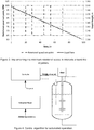
- Figure 3 shows an operational mode, in which the reduction of rotational speed is reverted, if the level of slurry is in between two impellers.
- This Figure further shows the decrease of the level of the slurry inside the vessel during withdrawal of the feeding vessel at a slow rate .
- the homogenization is further improved while withdrawing the slurry from the reactor.
- the risk of sedimentation is further reduced.
- this operational mode ensures both minimum sedimentation and minimum splashing when the level is close to the impellers.
- the best operational mode is achieved if the rotational speed is reduced when the level of the slurry is 0.5* D a (diameter of the impeller) above the vertically upper end of the impeller and 0.05* D a below above the vertically lower end of the impeller. If the rotational speed is reduced at levels of the slurry of ⁇ 0.5* D a above the vertically upper end of the impeller and/or again raised at levels of the slurry of ⁇ 0.05 D a below above the vertically lower end of the impeller, splashing is not completely avoided.
- Such an operation mode is especially advantageous in case of vessels having more than one impeller, all of which are connected to the vertical axis and, hence, cannot be driven with differing rotational speeds.
- each impeller can be driven at its own rotational speed it is also the best mode to achieve the reducing of the rotational speed for each impeller in said interval.
- Such a controlled process is depicted in Figure 4 including a control system comprising: (a) a level sensor, e.g. ultrasound level sensor; (b) an inferential control system to estimate the set point for the controller and (c) a controller, e.g. proportional-integral-derivative controller (PID), to regulate the rotational speed of the impeller.
- a level sensor e.g. ultrasound level sensor
- an inferential control system to estimate the set point for the controller
- a controller e.g. proportional-integral-derivative controller (PID)
- the minimum rotational speed is determined using the Zwietering correlation (equation (1)) and sent to the controller as a set-point for motor rotational speed.
- the level of the slurry inside the vessel is measured by the level sensor and also sent to the controller.
- the controller automatically enables reduced rotational speed of the impeller, which is close to the level of the slurry, if the slurry passes a certain predetermined trigger point monitored by the level sensor. Hence, at normal operation, the process follows a pre-defined pattern as that depicted in Figure 3 .
- the control algorithm adjusts the trigger times of the reducing of the rotational speed of the impeller based on the data provided by the sensors to the control system.
- a situation is depicted, where a sudden stop of withdrawal of the slurry happens (between 45 and 60 min).
- the control system reacts and shifts the reduction of the impeller rotational speed by the time delay needed to re-establish the normal withdrawal rate.
Landscapes
- Chemical & Material Sciences (AREA)
- Organic Chemistry (AREA)
- Chemical Kinetics & Catalysis (AREA)
- Engineering & Computer Science (AREA)
- Combustion & Propulsion (AREA)
- Manufacturing & Machinery (AREA)
- Mixers Of The Rotary Stirring Type (AREA)
Priority Applications (7)
| Application Number | Priority Date | Filing Date | Title |
|---|---|---|---|
| ES18209106T ES2972528T3 (es) | 2018-11-29 | 2018-11-29 | Método para proporcionar una suspensión homogénea que contenga partículas |
| EP18209106.6A EP3659702B1 (fr) | 2018-11-29 | 2018-11-29 | Procédé de fourniture d'une boue homogène contenant des particules |
| CA3121257A CA3121257A1 (fr) | 2018-11-29 | 2019-11-28 | Procede de fourniture d'une suspension homogene contenant des particules |
| PCT/EP2019/082862 WO2020109446A1 (fr) | 2018-11-29 | 2019-11-28 | Procédé de fourniture d'une suspension homogène contenant des particules |
| CN201980071392.1A CN113164895B (zh) | 2018-11-29 | 2019-11-28 | 提供均匀的含颗粒浆料的方法 |
| KR1020217009747A KR102582439B1 (ko) | 2018-11-29 | 2019-11-28 | 입자를 함유하는 균질한 슬러리를 제공하기 위한 공정 |
| US17/271,629 US11400427B2 (en) | 2018-11-29 | 2019-11-28 | Process for providing a homogenous slurry containing particles |
Applications Claiming Priority (1)
| Application Number | Priority Date | Filing Date | Title |
|---|---|---|---|
| EP18209106.6A EP3659702B1 (fr) | 2018-11-29 | 2018-11-29 | Procédé de fourniture d'une boue homogène contenant des particules |
Publications (3)
| Publication Number | Publication Date |
|---|---|
| EP3659702A1 true EP3659702A1 (fr) | 2020-06-03 |
| EP3659702C0 EP3659702C0 (fr) | 2024-02-21 |
| EP3659702B1 EP3659702B1 (fr) | 2024-02-21 |
Family
ID=64664028
Family Applications (1)
| Application Number | Title | Priority Date | Filing Date |
|---|---|---|---|
| EP18209106.6A Active EP3659702B1 (fr) | 2018-11-29 | 2018-11-29 | Procédé de fourniture d'une boue homogène contenant des particules |
Country Status (7)
| Country | Link |
|---|---|
| US (1) | US11400427B2 (fr) |
| EP (1) | EP3659702B1 (fr) |
| KR (1) | KR102582439B1 (fr) |
| CN (1) | CN113164895B (fr) |
| CA (1) | CA3121257A1 (fr) |
| ES (1) | ES2972528T3 (fr) |
| WO (1) | WO2020109446A1 (fr) |
Cited By (1)
| Publication number | Priority date | Publication date | Assignee | Title |
|---|---|---|---|---|
| WO2024172195A1 (fr) * | 2023-02-16 | 2024-08-22 | 솔리스 주식회사 | Appareil d'alimentation en produit chimique liquide utilisant un processus d'automatisation, et procédé associé |
Citations (4)
| Publication number | Priority date | Publication date | Assignee | Title |
|---|---|---|---|---|
| EP0446059A1 (fr) | 1990-03-09 | 1991-09-11 | BP Chemicals Limited | Procédé et appareil pour la polymérisation d'alpha-oléfines en phase gazeuse |
| EP1133350A1 (fr) | 1998-10-14 | 2001-09-19 | Borealis Technology Oy | Reacteur de prepolymerisation |
| WO2015177014A1 (fr) * | 2014-05-20 | 2015-11-26 | Basell Polyolefine Gmbh | Procédé de polymérisation de l'éthylène avec une performance de pompe à suspension améliorée |
| WO2016036722A1 (fr) * | 2014-09-02 | 2016-03-10 | Univation Technologies, Llc | Production de polyoléfines avec des catalyseurs à base de chrome |
Family Cites Families (5)
| Publication number | Priority date | Publication date | Assignee | Title |
|---|---|---|---|---|
| FR2618786B1 (fr) * | 1987-07-31 | 1989-12-01 | Bp Chimie Sa | Procede de polymerisation d'olefines en phase gazeuse dans un reacteur a lit fluidise |
| JP3643680B2 (ja) * | 1997-08-29 | 2005-04-27 | 三菱重工業株式会社 | 硫化カルシウムの酸化装置及びその操作方法 |
| JP2000143706A (ja) * | 1998-11-10 | 2000-05-26 | Mitsubishi Chemicals Corp | α−オレフィン重合体の製造方法 |
| EP2543432A1 (fr) * | 2010-03-01 | 2013-01-09 | Kureha Corporation | Appareil de contact à contre-courant solide-liquide de type colonne, et appareil et procédé pour nettoyer des particules solides |
| EP3526262A1 (fr) * | 2016-10-12 | 2019-08-21 | SABIC Global Technologies B.V. | Procédé de préparation d'un support solide pour un procatalyseur convenant à la polymérisation d'oléfines |
-
2018
- 2018-11-29 EP EP18209106.6A patent/EP3659702B1/fr active Active
- 2018-11-29 ES ES18209106T patent/ES2972528T3/es active Active
-
2019
- 2019-11-28 WO PCT/EP2019/082862 patent/WO2020109446A1/fr not_active Ceased
- 2019-11-28 US US17/271,629 patent/US11400427B2/en active Active
- 2019-11-28 CN CN201980071392.1A patent/CN113164895B/zh active Active
- 2019-11-28 CA CA3121257A patent/CA3121257A1/fr active Pending
- 2019-11-28 KR KR1020217009747A patent/KR102582439B1/ko active Active
Patent Citations (4)
| Publication number | Priority date | Publication date | Assignee | Title |
|---|---|---|---|---|
| EP0446059A1 (fr) | 1990-03-09 | 1991-09-11 | BP Chemicals Limited | Procédé et appareil pour la polymérisation d'alpha-oléfines en phase gazeuse |
| EP1133350A1 (fr) | 1998-10-14 | 2001-09-19 | Borealis Technology Oy | Reacteur de prepolymerisation |
| WO2015177014A1 (fr) * | 2014-05-20 | 2015-11-26 | Basell Polyolefine Gmbh | Procédé de polymérisation de l'éthylène avec une performance de pompe à suspension améliorée |
| WO2016036722A1 (fr) * | 2014-09-02 | 2016-03-10 | Univation Technologies, Llc | Production de polyoléfines avec des catalyseurs à base de chrome |
Non-Patent Citations (7)
| Title |
|---|
| "Comparing Impeller Performance for Solid-Suspension in the Transitional Flow Regime with Newtonian Fluids", CHEM. ENG. RES. DES., vol. 77, no. 8, November 1999 (1999-11-01), pages 721 - 727 |
| CLAIRE JACKSON ET AL: "Hydrated lime handling systems for thermal enhanced oil recovery: Toolkit Contents", 18 August 2016 (2016-08-18), XP055589445, Retrieved from the Internet <URL:https://watersmartsolutions.ca/wp-content/uploads/2018/08/LimeHandlingToolkit_Web_Version.pdf> [retrieved on 20160818] * |
| DILANJI BHAGYA WIJAYASEKARA: "MINIMUM AGITATION SPEED FOR SOLID SUSPENSION AND MIXING TIME IN A TORISPHERICAL-BOTTOMED PHARMACEUTICAL STIRRED TANK UNDER DIFFERENT BAFFLING CONDITIONS", 31 May 2010 (2010-05-31), XP055589253, Retrieved from the Internet <URL:http://archives.njit.edu/vol01/etd/2010s/2010/njit-etd2010-073/njit-etd2010-073.pdf> [retrieved on 20190516] * |
| MANOJ KANDAKURE ET AL: "CFD STUDY OF SLURRY HOMOGENIZER", SEVENTH INTERNATIONAL CONFERENCE ON CFD IN THE MINERALS AND PROCESS INDUSTRIES CSIRO, 1 December 2009 (2009-12-01), pages 9 - 11, XP055589407, Retrieved from the Internet <URL:http://www.cfd.com.au/cfd_conf09/PDFs/152KAN.pdf> * |
| MCCABE, W.; SMITH, J.; HARRIOTT, P.: "Unit Operations of Chemical Engineering", 1993, MCGRAW-HILL |
| MCCABE, W.; SMITH, J.; HARRIOTT, P.: "Unit Operations of Chemical Engineering", 1993, MCGRAW-HILL, pages: 265 |
| PAUL, E.; ATIEMO-OBENG, V.; KRESTA, S.: "Handbook of Industrial Mixing: Science and Practice", 2004, JOHN WILEY AND SONS, pages: 345 - 390 |
Cited By (2)
| Publication number | Priority date | Publication date | Assignee | Title |
|---|---|---|---|---|
| WO2024172195A1 (fr) * | 2023-02-16 | 2024-08-22 | 솔리스 주식회사 | Appareil d'alimentation en produit chimique liquide utilisant un processus d'automatisation, et procédé associé |
| KR20240127706A (ko) * | 2023-02-16 | 2024-08-23 | 솔리스 주식회사 | 자동화 공정을 이용한 약액공급장치 및 그 방법 |
Also Published As
| Publication number | Publication date |
|---|---|
| EP3659702C0 (fr) | 2024-02-21 |
| US20210339215A1 (en) | 2021-11-04 |
| KR20210045486A (ko) | 2021-04-26 |
| KR102582439B1 (ko) | 2023-09-22 |
| WO2020109446A1 (fr) | 2020-06-04 |
| US11400427B2 (en) | 2022-08-02 |
| CN113164895A (zh) | 2021-07-23 |
| CN113164895B (zh) | 2023-01-31 |
| ES2972528T3 (es) | 2024-06-13 |
| CA3121257A1 (fr) | 2020-06-04 |
| EP3659702B1 (fr) | 2024-02-21 |
Similar Documents
| Publication | Publication Date | Title |
|---|---|---|
| EP1208905B1 (fr) | Récipient agité pour produire une suspension de matières solides | |
| US7906597B2 (en) | Method and apparatus for preparing and supplying catalyst slurry to a polymerization reactor | |
| EP1556160B1 (fr) | Dispositif d'alimentation d'une suspension de catalyseur pour reacteur de polymerisation | |
| US8501883B2 (en) | Method and device for optimising catalyst supply to a polymerisation reactor | |
| EP2109498B1 (fr) | Appareil et procédé de polymérisation d'oléfines en phase liquide | |
| US20060104874A1 (en) | Segmented agitator reactor | |
| CN103038261A (zh) | 催化剂淤浆制备系统的用途 | |
| TW201713407A (zh) | 反應器以及丙交酯聚合方法 | |
| US11400427B2 (en) | Process for providing a homogenous slurry containing particles | |
| US20250051497A1 (en) | Process for preparing ethylene polymers in a slurry polymerization | |
| US11471847B2 (en) | Process for providing a homogenous slurry containing particles | |
| CN1917949A (zh) | 用于制备催化剂淤浆并将催化剂淤浆供应至聚合反应器的方法与装置 | |
| EP3268341B1 (fr) | Digesteur à base de réacteur colonne à bulles et son procédé d'utilisation | |
| JP7386973B2 (ja) | 塩化ビニル樹脂懸濁重合用バッチ式撹拌器およびそれを用いたバッチ式懸濁重合反応器 | |
| BR112021009904A2 (pt) | processo para fornecer uma lama homogênea contendo partículas | |
| BR112021009904B1 (pt) | Processo para fornecer uma lama homogênea contendo partículas | |
| JPS63150305A (ja) | オレフインの気相重合方法及び装置 | |
| WO2025240820A1 (fr) | Mélangeur de réaction d'acide phosphorique | |
| JP2002322205A (ja) | オレフィンの気相重合方法 | |
| WO2022038124A1 (fr) | Réacteur en boucle amélioré |
Legal Events
| Date | Code | Title | Description |
|---|---|---|---|
| PUAI | Public reference made under article 153(3) epc to a published international application that has entered the european phase |
Free format text: ORIGINAL CODE: 0009012 |
|
| STAA | Information on the status of an ep patent application or granted ep patent |
Free format text: STATUS: THE APPLICATION HAS BEEN PUBLISHED |
|
| AK | Designated contracting states |
Kind code of ref document: A1 Designated state(s): AL AT BE BG CH CY CZ DE DK EE ES FI FR GB GR HR HU IE IS IT LI LT LU LV MC MK MT NL NO PL PT RO RS SE SI SK SM TR |
|
| AX | Request for extension of the european patent |
Extension state: BA ME |
|
| STAA | Information on the status of an ep patent application or granted ep patent |
Free format text: STATUS: REQUEST FOR EXAMINATION WAS MADE |
|
| 17P | Request for examination filed |
Effective date: 20201203 |
|
| RBV | Designated contracting states (corrected) |
Designated state(s): AL AT BE BG CH CY CZ DE DK EE ES FI FR GB GR HR HU IE IS IT LI LT LU LV MC MK MT NL NO PL PT RO RS SE SI SK SM TR |
|
| STAA | Information on the status of an ep patent application or granted ep patent |
Free format text: STATUS: EXAMINATION IS IN PROGRESS |
|
| RAP3 | Party data changed (applicant data changed or rights of an application transferred) |
Owner name: BOREALIS AG |
|
| 17Q | First examination report despatched |
Effective date: 20220218 |
|
| GRAP | Despatch of communication of intention to grant a patent |
Free format text: ORIGINAL CODE: EPIDOSNIGR1 |
|
| STAA | Information on the status of an ep patent application or granted ep patent |
Free format text: STATUS: GRANT OF PATENT IS INTENDED |
|
| INTG | Intention to grant announced |
Effective date: 20231121 |
|
| GRAS | Grant fee paid |
Free format text: ORIGINAL CODE: EPIDOSNIGR3 |
|
| GRAA | (expected) grant |
Free format text: ORIGINAL CODE: 0009210 |
|
| STAA | Information on the status of an ep patent application or granted ep patent |
Free format text: STATUS: THE PATENT HAS BEEN GRANTED |
|
| AK | Designated contracting states |
Kind code of ref document: B1 Designated state(s): AL AT BE BG CH CY CZ DE DK EE ES FI FR GB GR HR HU IE IS IT LI LT LU LV MC MK MT NL NO PL PT RO RS SE SI SK SM TR |
|
| REG | Reference to a national code |
Ref country code: GB Ref legal event code: FG4D |
|
| REG | Reference to a national code |
Ref country code: CH Ref legal event code: EP |
|
| REG | Reference to a national code |
Ref country code: IE Ref legal event code: FG4D |
|
| REG | Reference to a national code |
Ref country code: DE Ref legal event code: R096 Ref document number: 602018065463 Country of ref document: DE |
|
| U01 | Request for unitary effect filed |
Effective date: 20240221 |
|
| U07 | Unitary effect registered |
Designated state(s): AT BE BG DE DK EE FI FR IT LT LU LV MT NL PT SE SI Effective date: 20240227 |
|
| REG | Reference to a national code |
Ref country code: LT Ref legal event code: MG9D |
|
| REG | Reference to a national code |
Ref country code: ES Ref legal event code: FG2A Ref document number: 2972528 Country of ref document: ES Kind code of ref document: T3 Effective date: 20240613 |
|
| PG25 | Lapsed in a contracting state [announced via postgrant information from national office to epo] |
Ref country code: IS Free format text: LAPSE BECAUSE OF FAILURE TO SUBMIT A TRANSLATION OF THE DESCRIPTION OR TO PAY THE FEE WITHIN THE PRESCRIBED TIME-LIMIT Effective date: 20240621 |
|
| PG25 | Lapsed in a contracting state [announced via postgrant information from national office to epo] |
Ref country code: GR Free format text: LAPSE BECAUSE OF FAILURE TO SUBMIT A TRANSLATION OF THE DESCRIPTION OR TO PAY THE FEE WITHIN THE PRESCRIBED TIME-LIMIT Effective date: 20240522 |
|
| PG25 | Lapsed in a contracting state [announced via postgrant information from national office to epo] |
Ref country code: RS Free format text: LAPSE BECAUSE OF FAILURE TO SUBMIT A TRANSLATION OF THE DESCRIPTION OR TO PAY THE FEE WITHIN THE PRESCRIBED TIME-LIMIT Effective date: 20240521 Ref country code: HR Free format text: LAPSE BECAUSE OF FAILURE TO SUBMIT A TRANSLATION OF THE DESCRIPTION OR TO PAY THE FEE WITHIN THE PRESCRIBED TIME-LIMIT Effective date: 20240221 |
|
| PG25 | Lapsed in a contracting state [announced via postgrant information from national office to epo] |
Ref country code: RS Free format text: LAPSE BECAUSE OF FAILURE TO SUBMIT A TRANSLATION OF THE DESCRIPTION OR TO PAY THE FEE WITHIN THE PRESCRIBED TIME-LIMIT Effective date: 20240521 Ref country code: NO Free format text: LAPSE BECAUSE OF FAILURE TO SUBMIT A TRANSLATION OF THE DESCRIPTION OR TO PAY THE FEE WITHIN THE PRESCRIBED TIME-LIMIT Effective date: 20240521 Ref country code: IS Free format text: LAPSE BECAUSE OF FAILURE TO SUBMIT A TRANSLATION OF THE DESCRIPTION OR TO PAY THE FEE WITHIN THE PRESCRIBED TIME-LIMIT Effective date: 20240621 Ref country code: HR Free format text: LAPSE BECAUSE OF FAILURE TO SUBMIT A TRANSLATION OF THE DESCRIPTION OR TO PAY THE FEE WITHIN THE PRESCRIBED TIME-LIMIT Effective date: 20240221 Ref country code: GR Free format text: LAPSE BECAUSE OF FAILURE TO SUBMIT A TRANSLATION OF THE DESCRIPTION OR TO PAY THE FEE WITHIN THE PRESCRIBED TIME-LIMIT Effective date: 20240522 |
|
| PG25 | Lapsed in a contracting state [announced via postgrant information from national office to epo] |
Ref country code: PL Free format text: LAPSE BECAUSE OF FAILURE TO SUBMIT A TRANSLATION OF THE DESCRIPTION OR TO PAY THE FEE WITHIN THE PRESCRIBED TIME-LIMIT Effective date: 20240221 |
|
| PG25 | Lapsed in a contracting state [announced via postgrant information from national office to epo] |
Ref country code: PL Free format text: LAPSE BECAUSE OF FAILURE TO SUBMIT A TRANSLATION OF THE DESCRIPTION OR TO PAY THE FEE WITHIN THE PRESCRIBED TIME-LIMIT Effective date: 20240221 |
|
| PG25 | Lapsed in a contracting state [announced via postgrant information from national office to epo] |
Ref country code: SM Free format text: LAPSE BECAUSE OF FAILURE TO SUBMIT A TRANSLATION OF THE DESCRIPTION OR TO PAY THE FEE WITHIN THE PRESCRIBED TIME-LIMIT Effective date: 20240221 |
|
| PG25 | Lapsed in a contracting state [announced via postgrant information from national office to epo] |
Ref country code: CZ Free format text: LAPSE BECAUSE OF FAILURE TO SUBMIT A TRANSLATION OF THE DESCRIPTION OR TO PAY THE FEE WITHIN THE PRESCRIBED TIME-LIMIT Effective date: 20240221 |
|
| PG25 | Lapsed in a contracting state [announced via postgrant information from national office to epo] |
Ref country code: SK Free format text: LAPSE BECAUSE OF FAILURE TO SUBMIT A TRANSLATION OF THE DESCRIPTION OR TO PAY THE FEE WITHIN THE PRESCRIBED TIME-LIMIT Effective date: 20240221 |
|
| PG25 | Lapsed in a contracting state [announced via postgrant information from national office to epo] |
Ref country code: SM Free format text: LAPSE BECAUSE OF FAILURE TO SUBMIT A TRANSLATION OF THE DESCRIPTION OR TO PAY THE FEE WITHIN THE PRESCRIBED TIME-LIMIT Effective date: 20240221 Ref country code: SK Free format text: LAPSE BECAUSE OF FAILURE TO SUBMIT A TRANSLATION OF THE DESCRIPTION OR TO PAY THE FEE WITHIN THE PRESCRIBED TIME-LIMIT Effective date: 20240221 Ref country code: RO Free format text: LAPSE BECAUSE OF FAILURE TO SUBMIT A TRANSLATION OF THE DESCRIPTION OR TO PAY THE FEE WITHIN THE PRESCRIBED TIME-LIMIT Effective date: 20240221 Ref country code: CZ Free format text: LAPSE BECAUSE OF FAILURE TO SUBMIT A TRANSLATION OF THE DESCRIPTION OR TO PAY THE FEE WITHIN THE PRESCRIBED TIME-LIMIT Effective date: 20240221 |
|
| REG | Reference to a national code |
Ref country code: DE Ref legal event code: R097 Ref document number: 602018065463 Country of ref document: DE |
|
| PLBE | No opposition filed within time limit |
Free format text: ORIGINAL CODE: 0009261 |
|
| STAA | Information on the status of an ep patent application or granted ep patent |
Free format text: STATUS: NO OPPOSITION FILED WITHIN TIME LIMIT |
|
| U20 | Renewal fee for the european patent with unitary effect paid |
Year of fee payment: 7 Effective date: 20241126 |
|
| 26N | No opposition filed |
Effective date: 20241122 |
|
| REG | Reference to a national code |
Ref country code: CH Ref legal event code: PL |
|
| PG25 | Lapsed in a contracting state [announced via postgrant information from national office to epo] |
Ref country code: MC Free format text: LAPSE BECAUSE OF FAILURE TO SUBMIT A TRANSLATION OF THE DESCRIPTION OR TO PAY THE FEE WITHIN THE PRESCRIBED TIME-LIMIT Effective date: 20240221 |
|
| REG | Reference to a national code |
Ref country code: CH Ref legal event code: PL |
|
| PG25 | Lapsed in a contracting state [announced via postgrant information from national office to epo] |
Ref country code: CH Free format text: LAPSE BECAUSE OF NON-PAYMENT OF DUE FEES Effective date: 20241130 |
|
| U1H | Name or address of the proprietor changed after the registration of the unitary effect |
Owner name: BOREALIS GMBH; AT |
|
| PG25 | Lapsed in a contracting state [announced via postgrant information from national office to epo] |
Ref country code: IE Free format text: LAPSE BECAUSE OF NON-PAYMENT OF DUE FEES Effective date: 20241129 |
|
| U20 | Renewal fee for the european patent with unitary effect paid |
Year of fee payment: 8 Effective date: 20251127 |
|
| PGFP | Annual fee paid to national office [announced via postgrant information from national office to epo] |
Ref country code: GB Payment date: 20251121 Year of fee payment: 8 |
|
| PGFP | Annual fee paid to national office [announced via postgrant information from national office to epo] |
Ref country code: ES Payment date: 20251229 Year of fee payment: 8 |
|
| PG25 | Lapsed in a contracting state [announced via postgrant information from national office to epo] |
Ref country code: HU Free format text: LAPSE BECAUSE OF FAILURE TO SUBMIT A TRANSLATION OF THE DESCRIPTION OR TO PAY THE FEE WITHIN THE PRESCRIBED TIME-LIMIT; INVALID AB INITIO Effective date: 20181129 |
|
| PG25 | Lapsed in a contracting state [announced via postgrant information from national office to epo] |
Ref country code: CY Free format text: LAPSE BECAUSE OF FAILURE TO SUBMIT A TRANSLATION OF THE DESCRIPTION OR TO PAY THE FEE WITHIN THE PRESCRIBED TIME-LIMIT; INVALID AB INITIO Effective date: 20181129 |