EP3659771A1 - Tragbares schneidewerkzeug für schiefer - Google Patents
Tragbares schneidewerkzeug für schiefer Download PDFInfo
- Publication number
- EP3659771A1 EP3659771A1 EP18208742.9A EP18208742A EP3659771A1 EP 3659771 A1 EP3659771 A1 EP 3659771A1 EP 18208742 A EP18208742 A EP 18208742A EP 3659771 A1 EP3659771 A1 EP 3659771A1
- Authority
- EP
- European Patent Office
- Prior art keywords
- cutting
- orifice
- guide rail
- fixing
- carriage
- Prior art date
- Legal status (The legal status is an assumption and is not a legal conclusion. Google has not performed a legal analysis and makes no representation as to the accuracy of the status listed.)
- Withdrawn
Links
- 230000000903 blocking effect Effects 0.000 claims abstract description 26
- 230000002441 reversible effect Effects 0.000 claims abstract description 16
- 239000010454 slate Substances 0.000 claims abstract description 14
- 239000000463 material Substances 0.000 claims description 11
- 239000002184 metal Substances 0.000 claims description 3
- 229910052751 metal Inorganic materials 0.000 claims description 3
- 239000002699 waste material Substances 0.000 description 5
- 230000000295 complement effect Effects 0.000 description 3
- 239000004568 cement Substances 0.000 description 2
- 239000000835 fiber Substances 0.000 description 2
- 230000001681 protective effect Effects 0.000 description 2
- 238000005096 rolling process Methods 0.000 description 2
- 240000008042 Zea mays Species 0.000 description 1
- HCHKCACWOHOZIP-UHFFFAOYSA-N Zinc Chemical compound [Zn] HCHKCACWOHOZIP-UHFFFAOYSA-N 0.000 description 1
- 238000010521 absorption reaction Methods 0.000 description 1
- 230000005484 gravity Effects 0.000 description 1
- 238000004080 punching Methods 0.000 description 1
- 230000035939 shock Effects 0.000 description 1
- 239000004575 stone Substances 0.000 description 1
- 229920002994 synthetic fiber Polymers 0.000 description 1
- 239000002023 wood Substances 0.000 description 1
- 229910052725 zinc Inorganic materials 0.000 description 1
- 239000011701 zinc Substances 0.000 description 1
Images
Classifications
-
- B—PERFORMING OPERATIONS; TRANSPORTING
- B26—HAND CUTTING TOOLS; CUTTING; SEVERING
- B26D—CUTTING; DETAILS COMMON TO MACHINES FOR PERFORATING, PUNCHING, CUTTING-OUT, STAMPING-OUT OR SEVERING
- B26D7/00—Details of apparatus for cutting, cutting-out, stamping-out, punching, perforating, or severing by means other than cutting
- B26D7/0006—Means for guiding the cutter
-
- B—PERFORMING OPERATIONS; TRANSPORTING
- B28—WORKING CEMENT, CLAY, OR STONE
- B28D—WORKING STONE OR STONE-LIKE MATERIALS
- B28D1/00—Working stone or stone-like materials, e.g. brick, concrete or glass, not provided for elsewhere; Machines, devices, tools therefor
- B28D1/22—Working stone or stone-like materials, e.g. brick, concrete or glass, not provided for elsewhere; Machines, devices, tools therefor by cutting, e.g. incising
- B28D1/225—Working stone or stone-like materials, e.g. brick, concrete or glass, not provided for elsewhere; Machines, devices, tools therefor by cutting, e.g. incising for scoring or breaking, e.g. tiles
-
- B—PERFORMING OPERATIONS; TRANSPORTING
- B28—WORKING CEMENT, CLAY, OR STONE
- B28D—WORKING STONE OR STONE-LIKE MATERIALS
- B28D1/00—Working stone or stone-like materials, e.g. brick, concrete or glass, not provided for elsewhere; Machines, devices, tools therefor
- B28D1/22—Working stone or stone-like materials, e.g. brick, concrete or glass, not provided for elsewhere; Machines, devices, tools therefor by cutting, e.g. incising
- B28D1/24—Working stone or stone-like materials, e.g. brick, concrete or glass, not provided for elsewhere; Machines, devices, tools therefor by cutting, e.g. incising with cutting discs
-
- B—PERFORMING OPERATIONS; TRANSPORTING
- B28—WORKING CEMENT, CLAY, OR STONE
- B28D—WORKING STONE OR STONE-LIKE MATERIALS
- B28D1/00—Working stone or stone-like materials, e.g. brick, concrete or glass, not provided for elsewhere; Machines, devices, tools therefor
- B28D1/32—Methods and apparatus specially adapted for working materials which can easily be split, e.g. mica, slate, schist
- B28D1/327—Methods and apparatus specially adapted for working materials which can easily be split, e.g. mica, slate, schist for cutting or shearing easily splittable working materials
-
- E—FIXED CONSTRUCTIONS
- E04—BUILDING
- E04D—ROOF COVERINGS; SKY-LIGHTS; GUTTERS; ROOF-WORKING TOOLS
- E04D15/00—Apparatus or tools for roof working
- E04D15/02—Apparatus or tools for roof working for roof coverings comprising tiles, shingles, or like roofing elements
Definitions
- the invention relates to a slate or plate cutting tool of similar material, in particular transportable and usable on a roof.
- the roofer cuts the slate plates on the ground to the general dimension desired, then mounts them on the roof to be covered and cuts them more finely using pliers or special hammers. Then he pierces them (also called “punching") and fixes them with hooks on the roof battens.
- One of the best known slate or fiber cement cutting tools is the CA600 model from JOUANEL.
- This tool comprises a frame delimiting a cutting table carrying a cutting slot above which a guide rail is arranged.
- a carriage fitted with a cutting disc engaged in the slot and a pull handle is mounted sliding on the rail.
- a first end of the rail comprises a reversible retaining means (generally a ball screw) of the carriage and the other end comprises a shock absorption buffer at the end of the stroke.
- the tool also includes a support table preferably provided with squaring stops.
- the support table is mounted coplanar with the cutting table to allow the support of part of the plate during cutting. It can be attached to the right or left of the cutting table depending on whether the operator is left or right handed.
- This tool is very heavy (over 22 kg) and cannot be carried on the roof by one person.
- Cutting waste discharged through the slot falls directly on the ground which can be swept later.
- the tool comprises a grip handle fixed to the body of the tool in a plane perpendicular to the cutting plane. It also includes a device for locking the carriage at one end of the rail during transport to prevent the latter from rolling along the guide and creating a dangerous imbalance due to its weight while the user holds the handle in one or two hands.
- This tool includes a frame raised by toothed feet and a chute for collecting cutting waste surmounted by the cutting table carrying the cutting slot.
- the collection chute is necessary to prevent waste from damaging the roof.
- the tool also includes a guide rail, a cutting carriage, as well as a support table to be fixed to the right or left of the cutting table depending on whether the user is right-handed or left-handed.
- the spacing of the feet is chosen so that they can be inserted between two battens to keep the tool on the roof and prevent it from slipping. Once the surface near the user is covered with slate, the latter slightly raises the tool to disengage the teeth from the batten and slides the tool near a new area to be covered.
- this tool has the advantage of allowing slates to be cut on the roof, that is to say at the place of use of the slates, it still has many drawbacks.
- the presence of the collecting chute between the cutting table and the feet makes the tool very unstable and the latter tilts systematically when the user leans on the support table.
- the tilting can be limited if the teeth of the feet bite strongly in the battens, but the latter is then damaged.
- the collecting chute includes a bottom mounted to pivot vertically, so that to empty the chute, the tool must be tilted to the side and the bottom pivoted. It is then necessary to shake the open tool to remove the waste, but given its size and weight in this position, it is common for the user to drop it. Furthermore, it is common for the bottom of the chute to come off during transport, which empties the chute in an undesired location and risks injuring the user.
- this tool comprises on the one hand a transport strap fixed to the frame and on the other hand a device for reversible blocking of the carriage at a first end of the rail to prevent the latter from rolling along the guide during movement. Thanks to the strap, the user can use both hands to climb on the roof.
- the tool is in great imbalance due to the locking arrangement and the tool weighs heavily on the shoulder of the user during the climb on the roof. Because of this imbalance, the tool can not be hoisted on the roof with a rope, at the risk of damaging the tool and / or the house.
- the objective of the present invention is to provide a slate cutting tool usable on a roof, light, practical, safe and economical.
- the tool comprises a very ergonomic transport system because it keeps the system balanced during transport and allows it to be hoisted without risk of imbalance.
- the cutting carriage comprises a stop orifice and in that the guide rail comprises a blocking orifice and a reversible fixing means for a locking rod engaged with the blocking orifice and with the stop orifice, in the locked position, the blocking orifice being arranged so that in the locked position, the cutting carriage is locked in the middle of the guide rail.
- the invention also relates to a grip handle for a tool for cutting slate or similar material, the tool comprising a cutting carriage mounted sliding along a guide rail and provided with a cutting disc and a disc protection casing, the casing consisting of two covers each comprising at least three fixing lugs.
- the handle comprises two pull handles connected to each other by a common end, each handle also comprising a free end, the two free ends and the common end comprising a cap for fixing to the casing shaped to cover at least partially, in the fixing position, a fixing lug of the first cover and a fixing lug of the second cover, so that the two covers of the casing cannot move away from each other by fixing position.
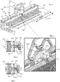
- the figure 1 illustrates an embodiment of a tool for cutting a slate plate, or similar material, according to the invention.
- the tool 100 is positioned between two battens A in the use position.
- the guide rail consists of two L-shaped profiles 121 (also called “angles") arranged facing each other and at a distance from each other to provide a passage for a cutting carriage 130 mounted to slide along the guide rail 120.
- the cutting carriage 130 comprises a grip handle 131 fixed to a housing 132.
- the latter protects a cutting disc 133 engaged in the cutting slot 111 and rotatably mounted in the housing by a shaft 134.
- the casing comprises bearings (not visible in the figure) arranged above and below the horizontal tracks 122 of the angles 121 of the guide rail.
- the tool 100 according to the invention comprises a system for blocking the cutting carriage 130 which is particularly advantageous since it allows the tool to be transported by the handle of the carriage 130, without any imbalance and in complete safety.
- the guide rail 120 comprises a locking hole 125 and a reversible fixing means 126 of a locking rod 190 in engagement with the locking hole 125.
- This locking rod 190 is intended to be inserted in taken with a stop orifice 134 carried by the cutting carriage 130 so that in the locked position, the cutting carriage is locked in the middle of the guide rail.
- the reversible fixing means 126 maintains the locking rod 190 in the retracted position to allow the cutting carriage to slide freely along the guide rail 120.
- the user positions the cutting carriage 130 in the middle of the guide rail 120, then it actuates the reversible fixing means 126 so that the locking rod 190 is inserted in engagement with the first stop orifice 134 carried by the cutting carriage 130. It then locks the first fixing means 126 so that the locking rod 190 prevents any translation of the cutting carriage 130 along the guide rail 120.
- the cutting carriage and the tool are stationary relative to each other and the user can grasp the assembly by the grip handle 131 and thus transport the tool.
- the central position of the carriage relative to the tool ensures a perfect balance of the assembly so that the transport of the tool is easy.
- the reversible fixing means 126 is a thread and the locking rod 190 is a threaded rod.
- the internal thread 126 can be carried by a metal insert 126a fixed to the guide rail (see figures 3 and 4 . This makes it possible to choose an insert having a greater mechanical resistance than that of the guide rail.
- the figure 2 illustrates a partial enlargement of the figure 1 located on the locking system of the cutting carriage on the guide rail.
- the stop orifice 134 is carried by a hollow head 134a fixed to the cutting carriage 130.
- the cutting carriage 130 comprises a rotation shaft 135 of the cutting disc 133, this shaft of rotation 135 comprising an end provided with a hollow head 134a carrying the stop orifice 134.
- the rotation shaft generally being in the middle of the cutting carriage 130, the blocking orifice 125 carried by the guide rail 120 is arranged on a median plane P of the tool 100 passing through the middle of the guide rail 120.
- the blocking orifice 125 is arranged at a length L / 2 from the end of the tool.
- the locking rod 190 is screwed into the thread of the blocking orifice 125 in order to be inserted into the stop orifice 134 of the cutting carriage 130.
- the blocking orifice 125 is located on a lateral wing 123 of one of the angles 121 constituting the guide rail 120.
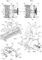
- the figure 3 schematically illustrates the position of use of the tool in which the locking rod 190 is retracted to leave the cutting carriage 130 slide freely along the guide rail as indicated by the arrow F1.
- the figure 4 illustrates the locking position in which the locking rod 190 is inserted into the stop orifice 134 carried by a hollow head 134a fixed to the cutting carriage 130. In this position, the carriage 130 is blocked in translation as illustrated by the crossed arrow F2.
- FIGS. 5 and 6 illustrate an alternative embodiment in which the locking rod 190 and secured to a reversible elastic restraint means 191 which keeps the rod in the locked position.
- the locking rod is also engaged with a ratchet device (not illustrated for the sake of clarity) allowing the selective passage between the retracted position illustrated in the figure 5 and the locking position shown in the figure 6 .
- the cutting carriage 130 may comprise a second stop orifice 134 and the guide rail 120 may comprise a second blocking orifice 125 arranged on the same median plane P of the tool as the first blocking orifice 125 , but opposite to the latter relative to the cutting carriage 130.
- the locking handle 131 according to the invention has a particularly advantageous structure, making it possible to combine the handling of the cutting carriage in use and the transport of the tool in the locking position.
- the gripping handle according to the invention also makes it possible to lighten the cutting carriage since it provides a function of fixing the covers of the protective casing of the cutting disc.
- the cutting carriage is provided with a cutting disc which must be covered to avoid the projection of cutting waste which may injure the user.
- the protective casing consists of two complementary covers which are fixed to each other.
- each cover comprises at least three fixing lugs 135a - 135b.
- the pins 135a - 135b are arranged at the edge of each cover so that when the covers 132a - 132b are one against the other, the fixing pins 135a - 135b are against each other, two by two, and preferably have a complementary shape, as illustrated in figure 8 .
- the grip 131 comprises two pull handles 131a - 131b connected to each other by a common end 131c, each pull handle 131a - 131b also comprising a free end 131d.
- the two free ends 131d and the common end 131c comprise a cap, respectively 131d1 and 131c1, for fixing to the casing.
- These caps are shaped to cover, at least partially, in the fixing position, a fixing lug 135a of the first cover 132a of the housing 132 and a fixing lug 135b of the second cover 132b of the housing 132. In this way, the two covers 132a - 132b of the housing cannot deviate from each other in the position of use.
- the cover of the common end 131c comprises a jumper 131c1 provided with holes 131c2 intended to receive a member for fixing the jumper on a fixing lug 135a of the first cover 132a and on a fixing lug 135b of the second cover 132b.
- This fixing member can be a screw, a nut, or a pin.
- the grip handle according to the invention also comprises a third carrying handle 131e connecting the two pulling handles 131a and 131b, and arranged above the common end 131c. In this way, the carrying handle is located in the middle of the cutting carriage, so that when this the latter is in the locked position in the middle of the tool, the user carries the tool substantially above its center of gravity.
- the load distribution is optimized and the transport of the tool is balanced while being very safe.
- the handle according to the invention therefore combines the function of carrying the tool and fixing the casing covers. It therefore makes it possible to limit the weight of the tool equipped with such a handle, while ensuring the carrying and pulling function of the cart to cut the slates.
- the tool according to the invention thus combines the blocking function of the cutting carriage with the tool carrying function.
Landscapes
- Engineering & Computer Science (AREA)
- Mechanical Engineering (AREA)
- Mining & Mineral Resources (AREA)
- Life Sciences & Earth Sciences (AREA)
- Forests & Forestry (AREA)
- Architecture (AREA)
- Civil Engineering (AREA)
- Structural Engineering (AREA)
- Processing Of Stones Or Stones Resemblance Materials (AREA)
Priority Applications (1)
| Application Number | Priority Date | Filing Date | Title |
|---|---|---|---|
| EP18208742.9A EP3659771A1 (de) | 2018-11-28 | 2018-11-28 | Tragbares schneidewerkzeug für schiefer |
Applications Claiming Priority (1)
| Application Number | Priority Date | Filing Date | Title |
|---|---|---|---|
| EP18208742.9A EP3659771A1 (de) | 2018-11-28 | 2018-11-28 | Tragbares schneidewerkzeug für schiefer |
Publications (1)
| Publication Number | Publication Date |
|---|---|
| EP3659771A1 true EP3659771A1 (de) | 2020-06-03 |
Family
ID=64556689
Family Applications (1)
| Application Number | Title | Priority Date | Filing Date |
|---|---|---|---|
| EP18208742.9A Withdrawn EP3659771A1 (de) | 2018-11-28 | 2018-11-28 | Tragbares schneidewerkzeug für schiefer |
Country Status (1)
| Country | Link |
|---|---|
| EP (1) | EP3659771A1 (de) |
Citations (3)
| Publication number | Priority date | Publication date | Assignee | Title |
|---|---|---|---|---|
| FR2847844A1 (fr) * | 2002-11-28 | 2004-06-04 | Participations G | Appareil pour le tranchage de materiaux en plaque |
| DE202007011845U1 (de) * | 2007-08-24 | 2007-10-18 | Dahm-Heuckmann, Gabriele | Vorrichtung zum Schneiden von Fliesen und Platten für Fliesenschneidemaschinen |
| US20180250807A1 (en) * | 2017-03-02 | 2018-09-06 | Terrifictools, Inc. | Truss-supported Tool Transport Apparatus |
-
2018
- 2018-11-28 EP EP18208742.9A patent/EP3659771A1/de not_active Withdrawn
Patent Citations (3)
| Publication number | Priority date | Publication date | Assignee | Title |
|---|---|---|---|---|
| FR2847844A1 (fr) * | 2002-11-28 | 2004-06-04 | Participations G | Appareil pour le tranchage de materiaux en plaque |
| DE202007011845U1 (de) * | 2007-08-24 | 2007-10-18 | Dahm-Heuckmann, Gabriele | Vorrichtung zum Schneiden von Fliesen und Platten für Fliesenschneidemaschinen |
| US20180250807A1 (en) * | 2017-03-02 | 2018-09-06 | Terrifictools, Inc. | Truss-supported Tool Transport Apparatus |
Non-Patent Citations (1)
| Title |
|---|
| DIMOS: "Coupe-ardoise MINI-CAD Confort", 31 December 2006 (2006-12-31), XP002791336, Retrieved from the Internet <URL:http://www.dimos-toitures.fr/web/ref61028_coupeardoise_minicad_confort.html> [retrieved on 20190515] * |
Similar Documents
| Publication | Publication Date | Title |
|---|---|---|
| EP0704150B1 (de) | Schneidzange, insbesondere Gartenschere | |
| EP2407211B1 (de) | Sicherheitsleinensystem zur Fallsicherung, Gleitstück, Kabelhalterung und Muffe | |
| FR2829726A1 (fr) | Chassis de chariot transporteur alimente par batterie | |
| CA2966959A1 (fr) | Mecanisme de levage pour un appareil de levage de plaques de construction, appareil de levage comportant un tel mecanisme, procede de levage a l'aide d'un tel appareil | |
| EP3659772B1 (de) | Stabilisiertes schneidewerkzeug für schiefer | |
| EP3659770B1 (de) | Schneidewerkzeug für schieferplatten mit abfallsammler | |
| EP2000613A1 (de) | Vorrichtung zum Schutz einer Öffnung | |
| CH685001A5 (fr) | Dispositif pour couper l'extrémité d'une lame rétractable d'un couteau polyvalent. | |
| EP0919316A1 (de) | Schienensäge | |
| EP4222336A1 (de) | Vorrichtung zur verwaltung des zugangs zu und der verwendung einer leiter | |
| EP0057654B1 (de) | Einrichtung zum Ablängen von Hölzern und dergleichen | |
| FR2732919A1 (fr) | Dispositif pour le fonctionnement manuel d'un couteau fermant a lame coulissante et amovible, a crans d'arrets, et multi-fonctions | |
| FR3072318B1 (fr) | Outil de decoupe d’ardoises stabilise | |
| EP1302607A1 (de) | Hebevorrichtung zur Montage von Platten an einer Unterdecke | |
| FR3072317B1 (fr) | Outil de decoupe de plaques d’ardoises a collecteur de dechets | |
| EP1564138B1 (de) | Übergangstreppe zwischen einer oberen und einer unteren Ebene eines Flugzeuges, und damit ausgerüstetes Flugzeug | |
| EP3215691B1 (de) | Mechanismus zur schwenkbaren befestigung eines plattenträgers an einem teleskopmast einer plattenhebevorrichtung und plattenhebevorrichtung mit diesem mechanismus | |
| EP1253280A2 (de) | Sicherheitsverankerungsvorrichtung | |
| EP1618276B1 (de) | Sicherheitsvorrichtung zur sicherung einer person beim arbeiten an einer leiter | |
| FR2540030A1 (fr) | Scie circulaire a chevalet oscillant | |
| FR3040651A3 (fr) | Fourreau pour la lame d’un outil de coupe a main, outil de coupe associe et ensemble comprenant un tel fourreau et un tel outil de coupe | |
| FR3094258A1 (fr) | Couteau à lame basculante et à manche/fourreau | |
| FR2846514A1 (fr) | Dispositif de manoeuvre pour le basculement controle d'une portion de tronc debite | |
| EP1416117B1 (de) | Einstellbare Leiter | |
| FR3020351A1 (fr) | Dispositif de chargement en dechets d'une benne de dechetterie depuis une plateforme |
Legal Events
| Date | Code | Title | Description |
|---|---|---|---|
| PUAI | Public reference made under article 153(3) epc to a published international application that has entered the european phase |
Free format text: ORIGINAL CODE: 0009012 |
|
| STAA | Information on the status of an ep patent application or granted ep patent |
Free format text: STATUS: THE APPLICATION HAS BEEN PUBLISHED |
|
| AK | Designated contracting states |
Kind code of ref document: A1 Designated state(s): AL AT BE BG CH CY CZ DE DK EE ES FI FR GB GR HR HU IE IS IT LI LT LU LV MC MK MT NL NO PL PT RO RS SE SI SK SM TR |
|
| AX | Request for extension of the european patent |
Extension state: BA ME |
|
| STAA | Information on the status of an ep patent application or granted ep patent |
Free format text: STATUS: THE APPLICATION IS DEEMED TO BE WITHDRAWN |
|
| 18D | Application deemed to be withdrawn |
Effective date: 20201204 |