EP3659836A1 - Procédé d'ajustement de la hauteur d'une semi-remorque - Google Patents
Procédé d'ajustement de la hauteur d'une semi-remorque Download PDFInfo
- Publication number
- EP3659836A1 EP3659836A1 EP19207772.5A EP19207772A EP3659836A1 EP 3659836 A1 EP3659836 A1 EP 3659836A1 EP 19207772 A EP19207772 A EP 19207772A EP 3659836 A1 EP3659836 A1 EP 3659836A1
- Authority
- EP
- European Patent Office
- Prior art keywords
- trailer
- chassis
- height
- inclination
- sensor
- Prior art date
- Legal status (The legal status is an assumption and is not a legal conclusion. Google has not performed a legal analysis and makes no representation as to the accuracy of the status listed.)
- Granted
Links
Images



Classifications
-
- B—PERFORMING OPERATIONS; TRANSPORTING
- B60—VEHICLES IN GENERAL
- B60G—VEHICLE SUSPENSION ARRANGEMENTS
- B60G17/00—Resilient suspensions having means for adjusting the spring or vibration-damper characteristics, for regulating the distance between a supporting surface and a sprung part of vehicle or for locking suspension during use to meet varying vehicular or surface conditions, e.g. due to speed or load
- B60G17/015—Resilient suspensions having means for adjusting the spring or vibration-damper characteristics, for regulating the distance between a supporting surface and a sprung part of vehicle or for locking suspension during use to meet varying vehicular or surface conditions, e.g. due to speed or load the regulating means comprising electric or electronic elements
- B60G17/016—Resilient suspensions having means for adjusting the spring or vibration-damper characteristics, for regulating the distance between a supporting surface and a sprung part of vehicle or for locking suspension during use to meet varying vehicular or surface conditions, e.g. due to speed or load the regulating means comprising electric or electronic elements characterised by their responsiveness, when the vehicle is travelling, to specific motion, a specific condition, or driver input
- B60G17/0165—Resilient suspensions having means for adjusting the spring or vibration-damper characteristics, for regulating the distance between a supporting surface and a sprung part of vehicle or for locking suspension during use to meet varying vehicular or surface conditions, e.g. due to speed or load the regulating means comprising electric or electronic elements characterised by their responsiveness, when the vehicle is travelling, to specific motion, a specific condition, or driver input to an external condition, e.g. rough road surface, side wind
-
- B—PERFORMING OPERATIONS; TRANSPORTING
- B60—VEHICLES IN GENERAL
- B60G—VEHICLE SUSPENSION ARRANGEMENTS
- B60G17/00—Resilient suspensions having means for adjusting the spring or vibration-damper characteristics, for regulating the distance between a supporting surface and a sprung part of vehicle or for locking suspension during use to meet varying vehicular or surface conditions, e.g. due to speed or load
- B60G17/015—Resilient suspensions having means for adjusting the spring or vibration-damper characteristics, for regulating the distance between a supporting surface and a sprung part of vehicle or for locking suspension during use to meet varying vehicular or surface conditions, e.g. due to speed or load the regulating means comprising electric or electronic elements
- B60G17/019—Resilient suspensions having means for adjusting the spring or vibration-damper characteristics, for regulating the distance between a supporting surface and a sprung part of vehicle or for locking suspension during use to meet varying vehicular or surface conditions, e.g. due to speed or load the regulating means comprising electric or electronic elements characterised by the type of sensor or the arrangement thereof
- B60G17/01908—Acceleration or inclination sensors
-
- B—PERFORMING OPERATIONS; TRANSPORTING
- B60—VEHICLES IN GENERAL
- B60G—VEHICLE SUSPENSION ARRANGEMENTS
- B60G2300/00—Indexing codes relating to the type of vehicle
- B60G2300/04—Trailers
- B60G2300/042—Semi-trailers
-
- B—PERFORMING OPERATIONS; TRANSPORTING
- B60—VEHICLES IN GENERAL
- B60G—VEHICLE SUSPENSION ARRANGEMENTS
- B60G2400/00—Indexing codes relating to detected, measured or calculated conditions or factors
- B60G2400/80—Exterior conditions
-
- B—PERFORMING OPERATIONS; TRANSPORTING
- B60—VEHICLES IN GENERAL
- B60G—VEHICLE SUSPENSION ARRANGEMENTS
- B60G2600/00—Indexing codes relating to particular elements, systems or processes used on suspension systems or suspension control systems
- B60G2600/02—Retarders, delaying means, dead zones, threshold values, cut-off frequency, timer interruption
-
- B—PERFORMING OPERATIONS; TRANSPORTING
- B60—VEHICLES IN GENERAL
- B60G—VEHICLE SUSPENSION ARRANGEMENTS
- B60G2800/00—Indexing codes relating to the type of movement or to the condition of the vehicle and to the end result to be achieved by the control action
- B60G2800/01—Attitude or posture control
- B60G2800/019—Inclination due to load distribution or road gradient
- B60G2800/0192—Inclination due to load distribution or road gradient longitudinal with regard to vehicle
Definitions
- the invention relates to a method for adapting the height of a trailer to the height of a motor vehicle with a fifth wheel plate, the trailer having a trailer chassis, at least one axle and a height-adjustable suspension, with an actual inclination of the trailer chassis relative to a straight line of the chassis, which runs in the direction of travel and parallel to a road surface.
- the invention relates to a control device, a system for performing the method and a trailer.
- a semi-trailer is understood here as a special form of a trailer, namely a trailer with a kingpin and for connection to a motor vehicle with a fifth wheel.
- the motor vehicle is also referred to as a tractor unit.
- Modern trailers are equipped with height-adjustable suspension, in particular with air suspension.
- the distance between the semi-trailer chassis and chassis can be adjusted with the suspension. Adaptation to different loads is also possible.
- Semi-trailers usually have a chassis with several axles that define a chassis level. In the case of a trailer with only one axle, the chassis level extends through this axis and parallel to a road surface.
- the trailer chassis is inclined relative to the chassis level, there are different distances between the trailer chassis and the chassis level. This can be useful in special situations, but is usually not desired while driving.
- an inclination of the trailer chassis relative to the direction of travel is considered, that is, an increasing or decreasing height of the trailer chassis in the direction of travel.
- a chassis straight line is defined that runs in the direction of travel and parallel to the road surface, against which the semi-trailer chassis can be inclined at a definable angle.
- chassis straight line runs parallel to the chassis level, can run in the chassis level, but also above or below.
- the only thing that is important here is the inclination of the trailer chassis relative to the straight line of the chassis, not the distance between the straight lines of the chassis and the surface of the road.
- the object of the present invention is to provide a method for automatically adapting the height of the trailer to the height of the motor vehicle.
- the process is carried out automatically.
- the actual inclination is equal to an angle ⁇ between the trailer chassis and the straight line of the chassis.
- an alignment parallel to the chassis straight line or chassis plane is preferred, that is, an angle of zero degrees.
- an angle greater or less than zero relative to the chassis line can also be specified as the target inclination.
- a target inclination with an angle greater than zero can be specified in order to optimize the air resistance of the combination of motor vehicle and trailer.
- At least signals from a sensor in the trailer are evaluated in order to determine the actual inclination ⁇ .
- the sensor is then part of a system with which the method is carried out.
- At least signals from two height sensors arranged at a distance from one another in the direction of travel are evaluated in order to determine the actual inclination ⁇ .
- the height sensors are arranged on the semi-trailer chassis and measure the distance to the chassis straight line or to the axles.
- the height sensors are preferably arranged vertically above the axes or at a small horizontal distance from them.
- Two heights are used to determine two heights, which differ if there is an actual inclination ⁇ > 0. From the difference in height and the geometry of the trailer, the size of the actual inclination ⁇ can be calculated, as can a height ⁇ SP of the fifth wheel.
- a particular advantage of using the height sensors mentioned is that a road surface with an incline or slope does not influence the measurement result and thus the determination of the actual inclination ⁇ .
- At least signals from an acceleration sensor or angle sensor are used to determine the actual inclination be evaluated.
- An angle sensor directly measures the misalignment of the trailer chassis relative to the straight line of the chassis, especially with two or more axles.
- An acceleration sensor is suitable for the indirect detection of the actual inclination.
- the acceleration sensor is arranged on the trailer chassis in such a way that when the trailer chassis is aligned parallel to the chassis straight line, the trailer acceleration in the direction of travel (X direction of the sensor) is detected.
- the acceleration sensor with its X direction is also inclined accordingly, so that it is no longer only the acceleration of the trailer chassis that is measured in the direction of travel, but also a component of the acceleration due to gravity g.
- the acceleration sensor with its X direction is also inclined accordingly, so that it is no longer only the acceleration of the trailer chassis that is measured in the direction of travel, but also a component of the acceleration due to gravity g.
- the acceleration sensor with its X direction is also inclined accordingly, so that it is no longer only the acceleration of the trailer chassis that is measured in the direction of travel, but also a component of the acceleration due to gravity g.
- the acceleration sensor with its X direction is also inclined accordingly, so that it is no longer only the acceleration of the trailer chassis that is measured in the direction of travel, but also a component of the acceleration due to gravity g.
- At least signals from a sensor in the motor vehicle are evaluated in order to determine the actual inclination ⁇ .
- the actual inclination of the trailer can also be recorded from the motor vehicle.
- suitable sensors must be provided in a suitable location in the motor vehicle.
- the signals from the relevant sensor can be transmitted from the motor vehicle to the semi-trailer to adjust the height-adjustable suspension. Transmission is possible, for example, by radio or via a standardized data interface or an analog line.
- At least signals from a sensor for determining the inclination of the saddle plate of the motor vehicle are evaluated.
- the inclination of the fifth wheel plate corresponds to the actual inclination of the trailer chassis.
- the actual inclination of the trailer can therefore be determined using a sensor on the fifth wheel.
- the angle sensor detects the angle of the fifth wheel plate relative to the motor vehicle chassis. If the latter has no inclination to a straight line of the chassis Motor vehicle has, automatically takes into account the inclination of the road surface. This means that an upward or downward gradient of the road surface does not affect the measurement.
- the acceleration sensor detects the proportion of gravitational acceleration already mentioned above.
- an inclination other than zero relative to the chassis straight line is specified as the target inclination.
- an angle of the target inclination is positive or negative, i.e. different from zero.
- Such a desired inclination can be advantageous in special applications, for example to optimize the air resistance or to adapt to a maximum permissible total height.
- the invention also relates to a control device set up to carry out the method according to one of claims 1 to 8.
- the control device has interfaces for controlling a height-adjustable suspension of a trailer and interfaces for signals from sensors or corresponding data, and software for carrying out the Procedure. It is preferably an electronic brake control device, in particular also for controlling an air suspension.
- the invention also relates to a system for carrying out the method according to one of claims 1 to 8.
- the system has a control device according to claim 9, at least one sensor for determining an actual inclination of a trailer and a height-adjustable suspension for the trailer.
- the height-adjustable suspension is advantageously an air suspension with supporting bellows.
- the invention also relates to a trailer with a system according to one of claims 10 or 11.
- a truck consists of a trailer 10 and a motor vehicle 11.
- the trailer 10 here has a chassis with several axles, in the present embodiment three axles 12, 13, 14.
- the axles 12, 13, 14 of the chassis form a chassis level 15.
- the Motor vehicle 11 has a saddle plate 16 for receiving a kingpin (not shown) of the trailer 10.
- the trailer 10 is provided with air suspension, so that a trailer chassis 17 is resiliently mounted relative to the chassis level 15.
- the air suspension is also adjustable in height.
- a front height sensor 18 and a rear height sensor 19 are arranged on the semitrailer chassis 17, with which the height of the semitrailer chassis 17 can be detected relative to the chassis level 15 or a level parallel to it.
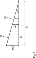
- the actual inclination of the semi-trailer chassis 17 is referred to here as the actual inclination, represented by an angle ⁇ between the semi-trailer chassis 17 and the chassis level 15. The same angle ⁇ results between the semi-trailer chassis 17 and a chassis straight line 20, which in Direction of travel runs parallel to the chassis level 15 through the rear height sensor 19.
- the distance L1 denotes the distance from the front axle 12 to a perpendicular 21. This is perpendicular to a road surface 22 and extends through the saddle plate 16.
- the chassis level 15 and the chassis straight line 20 run parallel to the road surface 22.
- a distance L3 denotes the distance between the rear axle 14 and the vertical 21.
- the trailer 10 has an electronic control unit 23 for the control of supporting bellows, not shown, of an air suspension.
- the control unit 23 can also be a control unit for an electronic braking system of the trailer 10.
- the height sensors 18, 19 are connected to the control unit 23. Data on the geometry of the trailer 10 are stored in the control device 23, for example the sections L1 and L3.
- An algorithm is implemented in the control unit 23, with which the actual inclination of the semi-trailer chassis 17 is automatically determined under certain operating conditions and compared with a target inclination.
- the height of the suspension is then adjusted by actuating the supporting bellows until the actual inclination corresponds to the target inclination.
- the automatic adaptation is preferably carried out directly after the connection of the trailer 10 to the motor vehicle 11, that is to say for example as soon as the Trailer 10 is connected to the power supply of the motor vehicle 11. Manual triggering of the automatic adjustment is also conceivable. An operator then does not have to assess the actual inclination from the outside and specifically set a different inclination. Rather, this is done by the control unit 23.
- a particular advantage of using the in Fig. 1 Height sensors 18, 19 shown lies in the fact that the height adjustment also works when the trailer 10 and the motor vehicle 11 are on a road surface with an upward or downward gradient.
- Fig. 3 shows another way of measuring the actual inclination ⁇ .
- An acceleration sensor 24 is used here as a sensor. Such sensors are installed in modern vehicles with an electronic braking system anyway or are at least cheaply available and can be retrofitted.
- the acceleration sensor 24 is connected to the trailer chassis 17 and can thus detect its actual inclination, at least when the trailer 10 and the motor vehicle 11 are on a horizontal road surface 22.
- the acceleration sensor 24 When the trailer chassis 17 is inclined, the acceleration sensor 24 indicates a component of the gravitational acceleration g, namely a x . This means the acceleration in the x-direction of the acceleration sensor 24. The more the trailer chassis 17 is inclined, the greater is a x .
- a vertical 25 through the acceleration sensor 24 is at a distance from the vertical 21 corresponding to the distance L2.
- the saddle plate 16 has a sensor 26 which indirectly or directly measures the actual inclination of the saddle plate 16 and transmits it to the control unit 23.
- the sensor 26 can be an angle sensor that directly measures the angle between the saddle plate 16 and a motor vehicle chassis 27. It is assumed that the actual inclination of the saddle plate 16 corresponds to the actual inclination ⁇ of the trailer chassis 17. The measurement is not influenced by an upward or downward gradient of the road surface 22.
- the senor 26 can be an acceleration sensor, as already shown in FIG Fig. 3 shown.
Landscapes
- Engineering & Computer Science (AREA)
- Mechanical Engineering (AREA)
- Vehicle Body Suspensions (AREA)
Applications Claiming Priority (1)
| Application Number | Priority Date | Filing Date | Title |
|---|---|---|---|
| DE102018130233.9A DE102018130233A1 (de) | 2018-11-29 | 2018-11-29 | Verfahren zur Anpassung der Höhe eines Aufliegers |
Publications (2)
| Publication Number | Publication Date |
|---|---|
| EP3659836A1 true EP3659836A1 (fr) | 2020-06-03 |
| EP3659836B1 EP3659836B1 (fr) | 2021-11-17 |
Family
ID=68502954
Family Applications (1)
| Application Number | Title | Priority Date | Filing Date |
|---|---|---|---|
| EP19207772.5A Active EP3659836B1 (fr) | 2018-11-29 | 2019-11-07 | Procédé d'ajustement de la hauteur d'une semi-remorque |
Country Status (2)
| Country | Link |
|---|---|
| EP (1) | EP3659836B1 (fr) |
| DE (1) | DE102018130233A1 (fr) |
Cited By (1)
| Publication number | Priority date | Publication date | Assignee | Title |
|---|---|---|---|---|
| DE102023115555A1 (de) | 2023-06-14 | 2024-12-19 | Zf Cv Systems Global Gmbh | Verfahren zur Ermittlung der Achslast eines Fahrzeugs, Fahrzeugsteuergerät und Fahrzeug |
Families Citing this family (1)
| Publication number | Priority date | Publication date | Assignee | Title |
|---|---|---|---|---|
| DE102022123359A1 (de) | 2022-09-13 | 2024-03-14 | Jost-Werke Deutschland Gmbh | Verfahren zum Kuppeln einer Sattelzugmaschine mit einem Sattelauflieger sowie Sattelzug mit einer Sattelzugmaschine und einem Sattelauflieger |
Citations (7)
| Publication number | Priority date | Publication date | Assignee | Title |
|---|---|---|---|---|
| DE19801546A1 (de) * | 1998-01-16 | 1999-07-22 | Koegel Fahrzeugwerke Ag | Verfahren zur Veränderung der Neigung des Fahrgestells eines mehrachsigen Lastkraftwagenanhängers, Federungsanlage für einen mehrachsigen Lastkraftwagenanhänger und mehrachsiger Lastkraftwagenanhänger |
| EP1449688A2 (fr) * | 2003-02-18 | 2004-08-25 | Bose Corporation | Planification de la trajectoire verticale pour un véhicule terrestre |
| DE102007015954A1 (de) * | 2007-04-03 | 2008-10-09 | Daimler Ag | Kraftfahrzeug mit wenigstens einer Achse mit Fluidfedereinheiten |
| DE102007051262A1 (de) * | 2007-10-26 | 2009-07-16 | Wabco Gmbh | Vorrichtung und Verfahren zur automatischen Einstellung des Horizontal-Niveaus eines Nutzfahrzeuges |
| DE102014012841A1 (de) * | 2014-08-29 | 2016-03-03 | Audi Ag | Niveauregelung, zugehöriges Betriebsverfahren und Kraftfahrzeug |
| DE102016119356A1 (de) * | 2015-10-13 | 2017-04-13 | Caterpillar Paving Products Inc. | System und verfahren zur steuerung der stabilität von fräsmaschinen |
| GB2552661A (en) * | 2016-08-01 | 2018-02-07 | Jaguar Land Rover Ltd | Vehicle levelling method and apparatus |
Family Cites Families (4)
| Publication number | Priority date | Publication date | Assignee | Title |
|---|---|---|---|---|
| FR2672561B1 (fr) * | 1991-02-08 | 1993-04-16 | Renault Vehicules Ind | Procede et dispositif destines a eviter les contacts entre tracteur et semi-remorque. |
| DE19752108A1 (de) * | 1997-11-25 | 1999-05-27 | Man Nutzfahrzeuge Ag | Verfahren zur Erhöhung des Freiganges zwischen einer Sattelzugmaschine und einem Auflieger |
| DE102007006265A1 (de) * | 2007-02-08 | 2008-08-14 | Daimler Ag | Sattelzugmaschine eines Sattelkraftwagens |
| US10369857B2 (en) * | 2016-12-01 | 2019-08-06 | Ford Global Technologies | Methods and apparatus to control vehicle tilt |
-
2018
- 2018-11-29 DE DE102018130233.9A patent/DE102018130233A1/de not_active Withdrawn
-
2019
- 2019-11-07 EP EP19207772.5A patent/EP3659836B1/fr active Active
Patent Citations (7)
| Publication number | Priority date | Publication date | Assignee | Title |
|---|---|---|---|---|
| DE19801546A1 (de) * | 1998-01-16 | 1999-07-22 | Koegel Fahrzeugwerke Ag | Verfahren zur Veränderung der Neigung des Fahrgestells eines mehrachsigen Lastkraftwagenanhängers, Federungsanlage für einen mehrachsigen Lastkraftwagenanhänger und mehrachsiger Lastkraftwagenanhänger |
| EP1449688A2 (fr) * | 2003-02-18 | 2004-08-25 | Bose Corporation | Planification de la trajectoire verticale pour un véhicule terrestre |
| DE102007015954A1 (de) * | 2007-04-03 | 2008-10-09 | Daimler Ag | Kraftfahrzeug mit wenigstens einer Achse mit Fluidfedereinheiten |
| DE102007051262A1 (de) * | 2007-10-26 | 2009-07-16 | Wabco Gmbh | Vorrichtung und Verfahren zur automatischen Einstellung des Horizontal-Niveaus eines Nutzfahrzeuges |
| DE102014012841A1 (de) * | 2014-08-29 | 2016-03-03 | Audi Ag | Niveauregelung, zugehöriges Betriebsverfahren und Kraftfahrzeug |
| DE102016119356A1 (de) * | 2015-10-13 | 2017-04-13 | Caterpillar Paving Products Inc. | System und verfahren zur steuerung der stabilität von fräsmaschinen |
| GB2552661A (en) * | 2016-08-01 | 2018-02-07 | Jaguar Land Rover Ltd | Vehicle levelling method and apparatus |
Cited By (1)
| Publication number | Priority date | Publication date | Assignee | Title |
|---|---|---|---|---|
| DE102023115555A1 (de) | 2023-06-14 | 2024-12-19 | Zf Cv Systems Global Gmbh | Verfahren zur Ermittlung der Achslast eines Fahrzeugs, Fahrzeugsteuergerät und Fahrzeug |
Also Published As
| Publication number | Publication date |
|---|---|
| EP3659836B1 (fr) | 2021-11-17 |
| DE102018130233A1 (de) | 2020-06-04 |
Similar Documents
| Publication | Publication Date | Title |
|---|---|---|
| EP2132539B1 (fr) | Procédé de détermination de la masse d'un véhicule | |
| EP1466763B1 (fr) | Procédé de fonctionnement d'un dispositif de réglage du niveau d'un véhicule automobile | |
| EP2787330B1 (fr) | Système de pesage et procédé destiné à peser un chargement d'un train routier basculant | |
| DE102017206055B4 (de) | Verfahren und Vorrichtung zur Dämpferregelung in einem Fahrzeug | |
| EP3466754B1 (fr) | Procédé et dispositif de réglage de la portée lumineuse d'un phare | |
| DE102013017407A1 (de) | Verfahren zur Überprüfung eines Beladungszustandes eines Aufliegers oder Anhängers eines Nutzfahrzeuges | |
| EP3812177A1 (fr) | Procédé de détermination de l'usure des pneus des bandages d'un véhicule et véhicule permettant de mettre en uvre ledit procédé | |
| DE102004060809A1 (de) | Verfahren und Vorrichtung zur Bestimmung massebezogener Größen eines Fahrzeugs | |
| DE602004011483T2 (de) | Anordnung und verfahren zur schätzung der höhe des schwerpunkts eines fahrzeugs | |
| DE102014009591A1 (de) | Verfahren zum Betrieb eines Kraftfahrzeugs und Kraftfahrzeug | |
| EP3659836B1 (fr) | Procédé d'ajustement de la hauteur d'une semi-remorque | |
| EP2390121B1 (fr) | Remorque de véhicule utilitaire et dispositif de commande pour agencement de ressort pneumatique | |
| DE102022123359A1 (de) | Verfahren zum Kuppeln einer Sattelzugmaschine mit einem Sattelauflieger sowie Sattelzug mit einer Sattelzugmaschine und einem Sattelauflieger | |
| DE102020123221A1 (de) | Verfahren zum Ermitteln und Überwachen eines Beladungszustandes von Kraftfahrzeugen auf Verkehrswegen | |
| EP4151438A1 (fr) | Véhicule automobile doté d'au moins un dispositif de détection | |
| EP4107016A1 (fr) | Détermination de grandeurs dynamiques d'un véhicule au moyen de capteurs agencés de manière répartie | |
| DE102020005183B4 (de) | Waageneinrichtung, Verfahren zum Ermitteln eines Schwerpunkts eines Kraftwagens sowie Verfahren zum Betreiben eines Kraftwagens | |
| EP4558373B1 (fr) | Commande de la hauteur d'un train de roulement au moyen d'un capteur d'embarquement de passagers | |
| DE102019005839A1 (de) | Verfahren zum Betreiben eines Fahrerassistenzsystems, sowie Fahrerassistenzsystem | |
| WO2025061447A1 (fr) | Procédé de fonctionnement d'un système de freinage électropneumatique pour un véhicule, en particulier un véhicule utilitaire, programme informatique et/ou support lisible par ordinateur, dispositif de commande et véhicule | |
| DE102023108319A1 (de) | Verfahren und Steuergerät zur Durchführung einer elektronischen Niveauregulierung einer Nutzfahrzeugkombination, insbesondere eines Volumen-Sattelzuges | |
| DE102012215692A1 (de) | Verfahren zur Überprüfung einer Vorspurkurve eines Kraftfahrzeuges mit Niveauregelanlage mit mindestens zwei Achsen sowie ein Computerprogrammprodukt zur Durchführung des Verfahrens | |
| DE102015003529B4 (de) | Verfahren zum Betrieb eines kraftfahrzeugseitigen Fahrerassistenzsystems und Kraftfahrzeug | |
| DE102009006617A1 (de) | Verfahren zur Ermittlung eines Beladungszustandes eines Fahrzeuges | |
| DE102023117135A1 (de) | Verfahren zur autarken Steuerung einer Bremsanlage eines Anhängerfahrzeuges eines Sattelzuges |
Legal Events
| Date | Code | Title | Description |
|---|---|---|---|
| PUAI | Public reference made under article 153(3) epc to a published international application that has entered the european phase |
Free format text: ORIGINAL CODE: 0009012 |
|
| STAA | Information on the status of an ep patent application or granted ep patent |
Free format text: STATUS: THE APPLICATION HAS BEEN PUBLISHED |
|
| AK | Designated contracting states |
Kind code of ref document: A1 Designated state(s): AL AT BE BG CH CY CZ DE DK EE ES FI FR GB GR HR HU IE IS IT LI LT LU LV MC MK MT NL NO PL PT RO RS SE SI SK SM TR |
|
| AX | Request for extension of the european patent |
Extension state: BA ME |
|
| STAA | Information on the status of an ep patent application or granted ep patent |
Free format text: STATUS: REQUEST FOR EXAMINATION WAS MADE |
|
| 17P | Request for examination filed |
Effective date: 20201203 |
|
| RBV | Designated contracting states (corrected) |
Designated state(s): AL AT BE BG CH CY CZ DE DK EE ES FI FR GB GR HR HU IE IS IT LI LT LU LV MC MK MT NL NO PL PT RO RS SE SI SK SM TR |
|
| GRAJ | Information related to disapproval of communication of intention to grant by the applicant or resumption of examination proceedings by the epo deleted |
Free format text: ORIGINAL CODE: EPIDOSDIGR1 |
|
| STAA | Information on the status of an ep patent application or granted ep patent |
Free format text: STATUS: GRANT OF PATENT IS INTENDED |
|
| GRAP | Despatch of communication of intention to grant a patent |
Free format text: ORIGINAL CODE: EPIDOSNIGR1 |
|
| INTG | Intention to grant announced |
Effective date: 20210324 |
|
| GRAJ | Information related to disapproval of communication of intention to grant by the applicant or resumption of examination proceedings by the epo deleted |
Free format text: ORIGINAL CODE: EPIDOSDIGR1 |
|
| STAA | Information on the status of an ep patent application or granted ep patent |
Free format text: STATUS: REQUEST FOR EXAMINATION WAS MADE |
|
| RAP3 | Party data changed (applicant data changed or rights of an application transferred) |
Owner name: ZF CV SYSTEMS HANNOVER GMBH |
|
| INTC | Intention to grant announced (deleted) | ||
| GRAP | Despatch of communication of intention to grant a patent |
Free format text: ORIGINAL CODE: EPIDOSNIGR1 |
|
| STAA | Information on the status of an ep patent application or granted ep patent |
Free format text: STATUS: GRANT OF PATENT IS INTENDED |
|
| INTG | Intention to grant announced |
Effective date: 20210614 |
|
| GRAS | Grant fee paid |
Free format text: ORIGINAL CODE: EPIDOSNIGR3 |
|
| GRAA | (expected) grant |
Free format text: ORIGINAL CODE: 0009210 |
|
| STAA | Information on the status of an ep patent application or granted ep patent |
Free format text: STATUS: THE PATENT HAS BEEN GRANTED |
|
| AK | Designated contracting states |
Kind code of ref document: B1 Designated state(s): AL AT BE BG CH CY CZ DE DK EE ES FI FR GB GR HR HU IE IS IT LI LT LU LV MC MK MT NL NO PL PT RO RS SE SI SK SM TR |
|
| REG | Reference to a national code |
Ref country code: GB Ref legal event code: FG4D Free format text: NOT ENGLISH |
|
| REG | Reference to a national code |
Ref country code: DE Ref legal event code: R096 Ref document number: 502019002769 Country of ref document: DE |
|
| REG | Reference to a national code |
Ref country code: IE Ref legal event code: FG4D Free format text: LANGUAGE OF EP DOCUMENT: GERMAN |
|
| REG | Reference to a national code |
Ref country code: AT Ref legal event code: REF Ref document number: 1447755 Country of ref document: AT Kind code of ref document: T Effective date: 20211215 |
|
| RAP2 | Party data changed (patent owner data changed or rights of a patent transferred) |
Owner name: ZF CV SYSTEMS EUROPE BV |
|
| REG | Reference to a national code |
Ref country code: LT Ref legal event code: MG9D |
|
| REG | Reference to a national code |
Ref country code: DE Ref legal event code: R081 Ref document number: 502019002769 Country of ref document: DE Owner name: ZF CV SYSTEMS EUROPE BV, BE Free format text: FORMER OWNER: ZF CV SYSTEMS HANNOVER GMBH, 30453 HANNOVER, DE |
|
| REG | Reference to a national code |
Ref country code: NL Ref legal event code: MP Effective date: 20211117 |
|
| PG25 | Lapsed in a contracting state [announced via postgrant information from national office to epo] |
Ref country code: RS Free format text: LAPSE BECAUSE OF FAILURE TO SUBMIT A TRANSLATION OF THE DESCRIPTION OR TO PAY THE FEE WITHIN THE PRESCRIBED TIME-LIMIT Effective date: 20211117 Ref country code: LT Free format text: LAPSE BECAUSE OF FAILURE TO SUBMIT A TRANSLATION OF THE DESCRIPTION OR TO PAY THE FEE WITHIN THE PRESCRIBED TIME-LIMIT Effective date: 20211117 Ref country code: FI Free format text: LAPSE BECAUSE OF FAILURE TO SUBMIT A TRANSLATION OF THE DESCRIPTION OR TO PAY THE FEE WITHIN THE PRESCRIBED TIME-LIMIT Effective date: 20211117 Ref country code: BG Free format text: LAPSE BECAUSE OF FAILURE TO SUBMIT A TRANSLATION OF THE DESCRIPTION OR TO PAY THE FEE WITHIN THE PRESCRIBED TIME-LIMIT Effective date: 20220217 |
|
| PG25 | Lapsed in a contracting state [announced via postgrant information from national office to epo] |
Ref country code: IS Free format text: LAPSE BECAUSE OF FAILURE TO SUBMIT A TRANSLATION OF THE DESCRIPTION OR TO PAY THE FEE WITHIN THE PRESCRIBED TIME-LIMIT Effective date: 20220317 Ref country code: SE Free format text: LAPSE BECAUSE OF FAILURE TO SUBMIT A TRANSLATION OF THE DESCRIPTION OR TO PAY THE FEE WITHIN THE PRESCRIBED TIME-LIMIT Effective date: 20211117 Ref country code: PT Free format text: LAPSE BECAUSE OF FAILURE TO SUBMIT A TRANSLATION OF THE DESCRIPTION OR TO PAY THE FEE WITHIN THE PRESCRIBED TIME-LIMIT Effective date: 20220317 Ref country code: PL Free format text: LAPSE BECAUSE OF FAILURE TO SUBMIT A TRANSLATION OF THE DESCRIPTION OR TO PAY THE FEE WITHIN THE PRESCRIBED TIME-LIMIT Effective date: 20211117 Ref country code: NO Free format text: LAPSE BECAUSE OF FAILURE TO SUBMIT A TRANSLATION OF THE DESCRIPTION OR TO PAY THE FEE WITHIN THE PRESCRIBED TIME-LIMIT Effective date: 20220217 Ref country code: NL Free format text: LAPSE BECAUSE OF FAILURE TO SUBMIT A TRANSLATION OF THE DESCRIPTION OR TO PAY THE FEE WITHIN THE PRESCRIBED TIME-LIMIT Effective date: 20211117 Ref country code: LV Free format text: LAPSE BECAUSE OF FAILURE TO SUBMIT A TRANSLATION OF THE DESCRIPTION OR TO PAY THE FEE WITHIN THE PRESCRIBED TIME-LIMIT Effective date: 20211117 Ref country code: HR Free format text: LAPSE BECAUSE OF FAILURE TO SUBMIT A TRANSLATION OF THE DESCRIPTION OR TO PAY THE FEE WITHIN THE PRESCRIBED TIME-LIMIT Effective date: 20211117 Ref country code: GR Free format text: LAPSE BECAUSE OF FAILURE TO SUBMIT A TRANSLATION OF THE DESCRIPTION OR TO PAY THE FEE WITHIN THE PRESCRIBED TIME-LIMIT Effective date: 20220218 Ref country code: ES Free format text: LAPSE BECAUSE OF FAILURE TO SUBMIT A TRANSLATION OF THE DESCRIPTION OR TO PAY THE FEE WITHIN THE PRESCRIBED TIME-LIMIT Effective date: 20211117 |
|
| PG25 | Lapsed in a contracting state [announced via postgrant information from national office to epo] |
Ref country code: SM Free format text: LAPSE BECAUSE OF FAILURE TO SUBMIT A TRANSLATION OF THE DESCRIPTION OR TO PAY THE FEE WITHIN THE PRESCRIBED TIME-LIMIT Effective date: 20211117 Ref country code: SK Free format text: LAPSE BECAUSE OF FAILURE TO SUBMIT A TRANSLATION OF THE DESCRIPTION OR TO PAY THE FEE WITHIN THE PRESCRIBED TIME-LIMIT Effective date: 20211117 Ref country code: RO Free format text: LAPSE BECAUSE OF FAILURE TO SUBMIT A TRANSLATION OF THE DESCRIPTION OR TO PAY THE FEE WITHIN THE PRESCRIBED TIME-LIMIT Effective date: 20211117 Ref country code: EE Free format text: LAPSE BECAUSE OF FAILURE TO SUBMIT A TRANSLATION OF THE DESCRIPTION OR TO PAY THE FEE WITHIN THE PRESCRIBED TIME-LIMIT Effective date: 20211117 Ref country code: DK Free format text: LAPSE BECAUSE OF FAILURE TO SUBMIT A TRANSLATION OF THE DESCRIPTION OR TO PAY THE FEE WITHIN THE PRESCRIBED TIME-LIMIT Effective date: 20211117 Ref country code: CZ Free format text: LAPSE BECAUSE OF FAILURE TO SUBMIT A TRANSLATION OF THE DESCRIPTION OR TO PAY THE FEE WITHIN THE PRESCRIBED TIME-LIMIT Effective date: 20211117 |
|
| REG | Reference to a national code |
Ref country code: DE Ref legal event code: R097 Ref document number: 502019002769 Country of ref document: DE |
|
| PLBE | No opposition filed within time limit |
Free format text: ORIGINAL CODE: 0009261 |
|
| STAA | Information on the status of an ep patent application or granted ep patent |
Free format text: STATUS: NO OPPOSITION FILED WITHIN TIME LIMIT |
|
| 26N | No opposition filed |
Effective date: 20220818 |
|
| PG25 | Lapsed in a contracting state [announced via postgrant information from national office to epo] |
Ref country code: AL Free format text: LAPSE BECAUSE OF FAILURE TO SUBMIT A TRANSLATION OF THE DESCRIPTION OR TO PAY THE FEE WITHIN THE PRESCRIBED TIME-LIMIT Effective date: 20211117 |
|
| PG25 | Lapsed in a contracting state [announced via postgrant information from national office to epo] |
Ref country code: SI Free format text: LAPSE BECAUSE OF FAILURE TO SUBMIT A TRANSLATION OF THE DESCRIPTION OR TO PAY THE FEE WITHIN THE PRESCRIBED TIME-LIMIT Effective date: 20211117 |
|
| PG25 | Lapsed in a contracting state [announced via postgrant information from national office to epo] |
Ref country code: IT Free format text: LAPSE BECAUSE OF FAILURE TO SUBMIT A TRANSLATION OF THE DESCRIPTION OR TO PAY THE FEE WITHIN THE PRESCRIBED TIME-LIMIT Effective date: 20211117 |
|
| PG25 | Lapsed in a contracting state [announced via postgrant information from national office to epo] |
Ref country code: MC Free format text: LAPSE BECAUSE OF FAILURE TO SUBMIT A TRANSLATION OF THE DESCRIPTION OR TO PAY THE FEE WITHIN THE PRESCRIBED TIME-LIMIT Effective date: 20211117 |
|
| REG | Reference to a national code |
Ref country code: CH Ref legal event code: PL |
|
| P01 | Opt-out of the competence of the unified patent court (upc) registered |
Effective date: 20230528 |
|
| REG | Reference to a national code |
Ref country code: BE Ref legal event code: MM Effective date: 20221130 |
|
| PG25 | Lapsed in a contracting state [announced via postgrant information from national office to epo] |
Ref country code: LI Free format text: LAPSE BECAUSE OF NON-PAYMENT OF DUE FEES Effective date: 20221130 Ref country code: CH Free format text: LAPSE BECAUSE OF NON-PAYMENT OF DUE FEES Effective date: 20221130 |
|
| PG25 | Lapsed in a contracting state [announced via postgrant information from national office to epo] |
Ref country code: LU Free format text: LAPSE BECAUSE OF NON-PAYMENT OF DUE FEES Effective date: 20221107 |
|
| PG25 | Lapsed in a contracting state [announced via postgrant information from national office to epo] |
Ref country code: IE Free format text: LAPSE BECAUSE OF NON-PAYMENT OF DUE FEES Effective date: 20221107 |
|
| PG25 | Lapsed in a contracting state [announced via postgrant information from national office to epo] |
Ref country code: FR Free format text: LAPSE BECAUSE OF NON-PAYMENT OF DUE FEES Effective date: 20221130 Ref country code: BE Free format text: LAPSE BECAUSE OF NON-PAYMENT OF DUE FEES Effective date: 20221130 |
|
| PG25 | Lapsed in a contracting state [announced via postgrant information from national office to epo] |
Ref country code: HU Free format text: LAPSE BECAUSE OF FAILURE TO SUBMIT A TRANSLATION OF THE DESCRIPTION OR TO PAY THE FEE WITHIN THE PRESCRIBED TIME-LIMIT; INVALID AB INITIO Effective date: 20191107 |
|
| PG25 | Lapsed in a contracting state [announced via postgrant information from national office to epo] |
Ref country code: CY Free format text: LAPSE BECAUSE OF FAILURE TO SUBMIT A TRANSLATION OF THE DESCRIPTION OR TO PAY THE FEE WITHIN THE PRESCRIBED TIME-LIMIT Effective date: 20211117 |
|
| PG25 | Lapsed in a contracting state [announced via postgrant information from national office to epo] |
Ref country code: MK Free format text: LAPSE BECAUSE OF FAILURE TO SUBMIT A TRANSLATION OF THE DESCRIPTION OR TO PAY THE FEE WITHIN THE PRESCRIBED TIME-LIMIT Effective date: 20211117 |
|
| GBPC | Gb: european patent ceased through non-payment of renewal fee |
Effective date: 20231107 |
|
| PG25 | Lapsed in a contracting state [announced via postgrant information from national office to epo] |
Ref country code: MT Free format text: LAPSE BECAUSE OF FAILURE TO SUBMIT A TRANSLATION OF THE DESCRIPTION OR TO PAY THE FEE WITHIN THE PRESCRIBED TIME-LIMIT Effective date: 20211117 |
|
| PG25 | Lapsed in a contracting state [announced via postgrant information from national office to epo] |
Ref country code: GB Free format text: LAPSE BECAUSE OF NON-PAYMENT OF DUE FEES Effective date: 20231107 |
|
| PG25 | Lapsed in a contracting state [announced via postgrant information from national office to epo] |
Ref country code: GB Free format text: LAPSE BECAUSE OF NON-PAYMENT OF DUE FEES Effective date: 20231107 |
|
| PG25 | Lapsed in a contracting state [announced via postgrant information from national office to epo] |
Ref country code: TR Free format text: LAPSE BECAUSE OF FAILURE TO SUBMIT A TRANSLATION OF THE DESCRIPTION OR TO PAY THE FEE WITHIN THE PRESCRIBED TIME-LIMIT Effective date: 20211117 |
|
| PGFP | Annual fee paid to national office [announced via postgrant information from national office to epo] |
Ref country code: DE Payment date: 20250910 Year of fee payment: 7 |
|
| PG25 | Lapsed in a contracting state [announced via postgrant information from national office to epo] |
Ref country code: AT Free format text: LAPSE BECAUSE OF NON-PAYMENT OF DUE FEES Effective date: 20241107 |
|
| REG | Reference to a national code |
Ref country code: AT Ref legal event code: MM01 Ref document number: 1447755 Country of ref document: AT Kind code of ref document: T Effective date: 20241107 |
|
| PGFP | Annual fee paid to national office [announced via postgrant information from national office to epo] |
Ref country code: AT Payment date: 20260410 Year of fee payment: 5 |