EP3659849B1 - Fahrgastraumstruktur - Google Patents
Fahrgastraumstruktur Download PDFInfo
- Publication number
- EP3659849B1 EP3659849B1 EP18847426.6A EP18847426A EP3659849B1 EP 3659849 B1 EP3659849 B1 EP 3659849B1 EP 18847426 A EP18847426 A EP 18847426A EP 3659849 B1 EP3659849 B1 EP 3659849B1
- Authority
- EP
- European Patent Office
- Prior art keywords
- driver
- vehicle
- vanishing point
- vehicle interior
- interior structure
- Prior art date
- Legal status (The legal status is an assumption and is not a legal conclusion. Google has not performed a legal analysis and makes no representation as to the accuracy of the status listed.)
- Active
Links
Images


Classifications
-
- B—PERFORMING OPERATIONS; TRANSPORTING
- B60—VEHICLES IN GENERAL
- B60J—WINDOWS, WINDSCREENS, NON-FIXED ROOFS, DOORS, OR SIMILAR DEVICES FOR VEHICLES; REMOVABLE EXTERNAL PROTECTIVE COVERINGS SPECIALLY ADAPTED FOR VEHICLES
- B60J1/00—Windows; Windscreens; Accessories therefor
- B60J1/02—Windows; Windscreens; Accessories therefor arranged at the vehicle front, e.g. structure of the glazing, mounting of the glazing
-
- B—PERFORMING OPERATIONS; TRANSPORTING
- B60—VEHICLES IN GENERAL
- B60J—WINDOWS, WINDSCREENS, NON-FIXED ROOFS, DOORS, OR SIMILAR DEVICES FOR VEHICLES; REMOVABLE EXTERNAL PROTECTIVE COVERINGS SPECIALLY ADAPTED FOR VEHICLES
- B60J5/00—Doors
- B60J5/04—Doors arranged at the vehicle sides
-
- B—PERFORMING OPERATIONS; TRANSPORTING
- B60—VEHICLES IN GENERAL
- B60K—ARRANGEMENT OR MOUNTING OF PROPULSION UNITS OR OF TRANSMISSIONS IN VEHICLES; ARRANGEMENT OR MOUNTING OF PLURAL DIVERSE PRIME-MOVERS IN VEHICLES; AUXILIARY DRIVES FOR VEHICLES; INSTRUMENTATION OR DASHBOARDS FOR VEHICLES; ARRANGEMENTS IN CONNECTION WITH COOLING, AIR INTAKE, GAS EXHAUST OR FUEL SUPPLY OF PROPULSION UNITS IN VEHICLES
- B60K35/00—Instruments specially adapted for vehicles; Arrangement of instruments in or on vehicles
- B60K35/20—Output arrangements, i.e. from vehicle to user, associated with vehicle functions or specially adapted therefor
- B60K35/21—Output arrangements, i.e. from vehicle to user, associated with vehicle functions or specially adapted therefor using visual output, e.g. blinking lights or matrix displays
- B60K35/22—Display screens
-
- B—PERFORMING OPERATIONS; TRANSPORTING
- B60—VEHICLES IN GENERAL
- B60K—ARRANGEMENT OR MOUNTING OF PROPULSION UNITS OR OF TRANSMISSIONS IN VEHICLES; ARRANGEMENT OR MOUNTING OF PLURAL DIVERSE PRIME-MOVERS IN VEHICLES; AUXILIARY DRIVES FOR VEHICLES; INSTRUMENTATION OR DASHBOARDS FOR VEHICLES; ARRANGEMENTS IN CONNECTION WITH COOLING, AIR INTAKE, GAS EXHAUST OR FUEL SUPPLY OF PROPULSION UNITS IN VEHICLES
- B60K35/00—Instruments specially adapted for vehicles; Arrangement of instruments in or on vehicles
- B60K35/20—Output arrangements, i.e. from vehicle to user, associated with vehicle functions or specially adapted therefor
- B60K35/28—Output arrangements, i.e. from vehicle to user, associated with vehicle functions or specially adapted therefor characterised by the type of the output information, e.g. video entertainment or vehicle dynamics information; characterised by the purpose of the output information, e.g. for attracting the attention of the driver
- B60K35/285—Output arrangements, i.e. from vehicle to user, associated with vehicle functions or specially adapted therefor characterised by the type of the output information, e.g. video entertainment or vehicle dynamics information; characterised by the purpose of the output information, e.g. for attracting the attention of the driver for improving awareness by directing driver's gaze direction or eye points
-
- B—PERFORMING OPERATIONS; TRANSPORTING
- B60—VEHICLES IN GENERAL
- B60K—ARRANGEMENT OR MOUNTING OF PROPULSION UNITS OR OF TRANSMISSIONS IN VEHICLES; ARRANGEMENT OR MOUNTING OF PLURAL DIVERSE PRIME-MOVERS IN VEHICLES; AUXILIARY DRIVES FOR VEHICLES; INSTRUMENTATION OR DASHBOARDS FOR VEHICLES; ARRANGEMENTS IN CONNECTION WITH COOLING, AIR INTAKE, GAS EXHAUST OR FUEL SUPPLY OF PROPULSION UNITS IN VEHICLES
- B60K35/00—Instruments specially adapted for vehicles; Arrangement of instruments in or on vehicles
- B60K35/60—Instruments characterised by their location or relative disposition in or on vehicles
-
- B—PERFORMING OPERATIONS; TRANSPORTING
- B60—VEHICLES IN GENERAL
- B60K—ARRANGEMENT OR MOUNTING OF PROPULSION UNITS OR OF TRANSMISSIONS IN VEHICLES; ARRANGEMENT OR MOUNTING OF PLURAL DIVERSE PRIME-MOVERS IN VEHICLES; AUXILIARY DRIVES FOR VEHICLES; INSTRUMENTATION OR DASHBOARDS FOR VEHICLES; ARRANGEMENTS IN CONNECTION WITH COOLING, AIR INTAKE, GAS EXHAUST OR FUEL SUPPLY OF PROPULSION UNITS IN VEHICLES
- B60K37/00—Dashboards
- B60K37/20—Dashboard panels
-
- B—PERFORMING OPERATIONS; TRANSPORTING
- B60—VEHICLES IN GENERAL
- B60R—VEHICLES, VEHICLE FITTINGS, OR VEHICLE PARTS, NOT OTHERWISE PROVIDED FOR
- B60R13/00—Elements for body-finishing, identifying, or decorating; Arrangements or adaptations for advertising purposes
- B60R13/02—Internal Trim mouldings ; Internal Ledges; Wall liners for passenger compartments; Roof liners
- B60R13/0256—Dashboard liners
-
- B—PERFORMING OPERATIONS; TRANSPORTING
- B60—VEHICLES IN GENERAL
- B60K—ARRANGEMENT OR MOUNTING OF PROPULSION UNITS OR OF TRANSMISSIONS IN VEHICLES; ARRANGEMENT OR MOUNTING OF PLURAL DIVERSE PRIME-MOVERS IN VEHICLES; AUXILIARY DRIVES FOR VEHICLES; INSTRUMENTATION OR DASHBOARDS FOR VEHICLES; ARRANGEMENTS IN CONNECTION WITH COOLING, AIR INTAKE, GAS EXHAUST OR FUEL SUPPLY OF PROPULSION UNITS IN VEHICLES
- B60K2360/00—Indexing scheme associated with groups B60K35/00 or B60K37/00 relating to details of instruments or dashboards
- B60K2360/60—Structural details of dashboards or instruments
- B60K2360/68—Features of instruments
- B60K2360/688—Frames or decorative parts
-
- B—PERFORMING OPERATIONS; TRANSPORTING
- B60—VEHICLES IN GENERAL
- B60K—ARRANGEMENT OR MOUNTING OF PROPULSION UNITS OR OF TRANSMISSIONS IN VEHICLES; ARRANGEMENT OR MOUNTING OF PLURAL DIVERSE PRIME-MOVERS IN VEHICLES; AUXILIARY DRIVES FOR VEHICLES; INSTRUMENTATION OR DASHBOARDS FOR VEHICLES; ARRANGEMENTS IN CONNECTION WITH COOLING, AIR INTAKE, GAS EXHAUST OR FUEL SUPPLY OF PROPULSION UNITS IN VEHICLES
- B60K2360/00—Indexing scheme associated with groups B60K35/00 or B60K37/00 relating to details of instruments or dashboards
- B60K2360/60—Structural details of dashboards or instruments
- B60K2360/68—Features of instruments
- B60K2360/691—Housings
-
- B—PERFORMING OPERATIONS; TRANSPORTING
- B60—VEHICLES IN GENERAL
- B60K—ARRANGEMENT OR MOUNTING OF PROPULSION UNITS OR OF TRANSMISSIONS IN VEHICLES; ARRANGEMENT OR MOUNTING OF PLURAL DIVERSE PRIME-MOVERS IN VEHICLES; AUXILIARY DRIVES FOR VEHICLES; INSTRUMENTATION OR DASHBOARDS FOR VEHICLES; ARRANGEMENTS IN CONNECTION WITH COOLING, AIR INTAKE, GAS EXHAUST OR FUEL SUPPLY OF PROPULSION UNITS IN VEHICLES
- B60K2360/00—Indexing scheme associated with groups B60K35/00 or B60K37/00 relating to details of instruments or dashboards
- B60K2360/77—Instrument locations other than the dashboard
- B60K2360/774—Instrument locations other than the dashboard on or in the centre console
-
- B—PERFORMING OPERATIONS; TRANSPORTING
- B60—VEHICLES IN GENERAL
- B60K—ARRANGEMENT OR MOUNTING OF PROPULSION UNITS OR OF TRANSMISSIONS IN VEHICLES; ARRANGEMENT OR MOUNTING OF PLURAL DIVERSE PRIME-MOVERS IN VEHICLES; AUXILIARY DRIVES FOR VEHICLES; INSTRUMENTATION OR DASHBOARDS FOR VEHICLES; ARRANGEMENTS IN CONNECTION WITH COOLING, AIR INTAKE, GAS EXHAUST OR FUEL SUPPLY OF PROPULSION UNITS IN VEHICLES
- B60K2360/00—Indexing scheme associated with groups B60K35/00 or B60K37/00 relating to details of instruments or dashboards
- B60K2360/77—Instrument locations other than the dashboard
- B60K2360/782—Instrument locations other than the dashboard on the steering wheel
-
- B—PERFORMING OPERATIONS; TRANSPORTING
- B60—VEHICLES IN GENERAL
- B60K—ARRANGEMENT OR MOUNTING OF PROPULSION UNITS OR OF TRANSMISSIONS IN VEHICLES; ARRANGEMENT OR MOUNTING OF PLURAL DIVERSE PRIME-MOVERS IN VEHICLES; AUXILIARY DRIVES FOR VEHICLES; INSTRUMENTATION OR DASHBOARDS FOR VEHICLES; ARRANGEMENTS IN CONNECTION WITH COOLING, AIR INTAKE, GAS EXHAUST OR FUEL SUPPLY OF PROPULSION UNITS IN VEHICLES
- B60K2360/00—Indexing scheme associated with groups B60K35/00 or B60K37/00 relating to details of instruments or dashboards
- B60K2360/77—Instrument locations other than the dashboard
- B60K2360/785—Instrument locations other than the dashboard on or in relation to the windshield or windows
Definitions
- the present invention relates to an interior structure for a vehicle, or a vehicle interior structure.
- a window frame structure of an automotive vehicle is described in JP 2015-217860A .
- a virtual edge of a front windshield is displayed on the front windshield such that it extends in an upward-downward direction along the vicinity of a front pillar in a manner visible to a driver.
- This virtual edge is formed such that it is gradually spaced apart from the front pillar in a direction from a lower end toward an upper end of the front pillar.
- the driver feels that an optical flow extending from a vanishing point is vanished at the virtual edge, so that it is possible to ensure the same visual state as that under a hypothetical condition that the front pillar is in a state close to upright. This makes it possible to improve a vehicle speed feeling to be felt by a driver.
- an interior structure for a vehicle according to the preamble portion of claim 1 is known from document JP 2017-056909 A , wherein the center point of the steering wheel and the mid-top of the instrument cluster hood are located in a projection plane as viewed by the driver on an axis line extending to the driver from the vanishing point.
- a further interior structure for a vehicle having an instrument cluster hood arranged in a specific position relative to the steering wheel, is known from US 2015/243046 A1 .
- a vehicle speed feeling to be felt by a driver is improved by displaying the virtual edge of the front windshield along the vicinity of the front pillar.
- information to be acquired by a driver who drives a vehicle is not simply based on an external landscape recognized through a front window and the like, but is also influenced by a vehicle interior structural component which comes into driver's field-of-view together with the external landscape. Therefore, information about an external environment sensible by the driver becomes different depending on a vehicle interior structural component which comes into driver's field-of-view. That is, depending on a vehicle interior structural component which comes into driver's field-of-view, an error in information acquired by the driver is likely to become large, or wrong information is likely to be recognized by the driver. According to researches of the present inventors, it has been revealed that the shape or the like of a vehicle interior structural component has a strong influence on accuracy with which a driver figures out the position of an own vehicle.
- the present invention provides an interior structure for a vehicle according to claim 1, which comprises a vehicle interior structural component arranged within a field-of-view of a driver, wherein at least one outline of the vehicle interior structural component is approximately coincident with an axis line oriented toward a vehicle interior of the vehicle, among a plurality of axis lines radially extending from a vanishing point defined when the driver visually views forwardly while being seated in a driver seat.
- the driver when a driver drives a certain vehicle, the driver can easily drive the vehicle to travel along an appropriate zone in a lane, whereas, when the same driver drives another vehicle, traveling in a deviated zone or in a zigzag pattern in a lane is likely to occur.
- axis line sensibility i.e., sensibility to an axis line to be imagined in driver's head is disturbed, and thereby the axis line to be imagined is likely to deviate from an actual axis line.
- At least one outline of the vehicle interior structural component is approximately coincident with an axis line oriented toward a vehicle interior of the vehicle, among a plurality of axis lines radially extending from a vanishing point defined when the driver visually views forwardly while being seated in a driver seat.
- the driver can adequately imagine a virtual axis line extending to a position beneath his/her feet, so that it becomes possible for the driver to easily figure out his/her position in a space where the vehicle travels. This makes it possible for the driver to easily drive the vehicle to travel along an appropriate zone in a traveling lane.
- the at least one outline of the vehicle interior structural component is visually viewed such that it is approximately coincident with the axis line oriented toward the vehicle interior, in a forward field-of-view of the driver seated in the driver seat.
- the outline of the vehicle interior structural component is approximately coincident with the axis line oriented from the vanishing point toward the vehicle interior, in the forward field-of-view of the driver seated in the driver seat, so that an axis line imagined by the driver is less likely to deviate from the actual axis line, and thereby the driver can easily drive the vehicle to travel along an appropriate zone in a traveling lane.
- the vehicle interior structural component is a window frame of a side window, wherein the interior structure is configured such that a lower edge of the window frame is approximately coincident with the axis line oriented from the vanishing point toward the vehicle interior.
- the interior structure is configured such that the lower edge of the window frame is approximately coincident with the axis line oriented from the vanishing point toward the vehicle interior, so that the axis line extending from the vanishing point is approximately coincident with the outline of the vehicle interior structural component over a relatively long distance, and thereby it is possible to effectively assist the "axis feeling" of the driver.
- the vehicle interior structural component is a center display arranged on an instrument panel of the vehicle, wherein the interior structure is configured such that each of opposite lateral edges of the center display is approximately coincident with the axis line oriented from the vanishing point toward the vehicle interior.
- the interior structure is configured such that each of the lateral edges of the center display is approximately coincident with the axis line oriented from the vanishing point toward the vehicle interior, so that an outline assisting the "axis feeling" of the driver can be arranged on the side of a of the vehicle when viewed from the driver, and thereby the driver can obtain a more accurate axis feeling.
- the vehicle interior structural component is an instrument cluster hood covering an instrument cluster of the vehicle, wherein the interior structure is configured such that a given region of an outer edge of the instrument cluster hood is approximately coincident with the axis line oriented from the vanishing point toward the vehicle interior.
- the given region of the outer edge of the instrument cluster hood is approximately coincident with the axis line oriented from the vanishing point toward the vehicle interior, so that the "axis feeling" can be assisted in the vicinity of the center of the field-of-view of the driver to effectively enhance the "axis feeling" of the driver.
- an upper end of an instrument panel arranged in front of the driver seat to serve as the vehicle interior structural component is provided with a vanishing point mark at a position on the axis line extending to the driver from the vanishing point defined when the driver visually views forwardly while being seated in the driver seat.
- the upper end of the instrument panel is provided with the vanishing point mark at a position on the axis line extending to the driver from the vanishing point defined when the driver visually views forwardly, so that the driver can easily recognize the vanishing point.
- the driver becomes more likely to direct attention toward an axis line extending from the vanishing point to the driver. This makes it possible for the driver to easily figure out his/her position in a space where the vehicle travels and to easily drive the vehicle to travel along an appropriate zone in a traveling lane.
- the vanishing point mark formed on the upper end of the instrument panel is a protrusion formed on the instrument panel.
- the vanishing point mark is composed of a protrusion, so that it impossible to provide the vanishing point mark at a given position without spoiling aesthetic quality of the vehicle interior structure.
- the protrusion formed on the instrument panel is provided at a top of an instrument cluster hood of the instrument panel.
- the protrusion is provided at the top of the instrument cluster hood of the instrument panel, so that the protrusion serving as the vanishing point mark is located at an approximately center of the field-of-view of the driver.
- the driver is apt to naturally look at the protrusion, so that it is possible for the driver to effectively direct attention toward an axis line extending from the vanishing point.
- the vanishing point mark formed on the upper end of the instrument panel is located above an upper end of a steering wheel of the vehicle when viewed from the driver seated in the driver seat of the vehicle.
- the vanishing point mark is located above the upper end of the steering wheel of the vehicle when viewed from the driver seated in the driver seat of the vehicle, so that it is possible to allow the vanishing point mark to always come into the driver's field-of-view together with an external landscape, thereby always prompting the driver to direct attention toward the vanishing point.
- the vehicle interior structure of the present invention makes it possible to allow a driver to easily and accurately figure out the position of an own vehicle.
- FIG. 1 is a diagram schematically showing an external landscape visually viewed by a driver who drives a vehicle.
- a driver appropriately takes driving actions, such as steering manipulation, by figuring out the position of an own vehicle in a space where the vehicle travels, while visually viewing an external landscape, as shown in FIG. 1 .
- the driver figures out the position of the own vehicle in the space while recognizing a distant vanishing point P, and virtual axis lines A1 to A8, etc., extending radially from the vanishing points, in an unconscious manner.
- the vanishing point P is a point on a distant horizon line L.
- the vanishing point P is located at an intersection point of the axis line A2 and the axis line A7 each coincident with a respective one of opposed border lines (edges) of the lane.
- the virtual axis lines A extending from the vanishing point P are blocked halfway by a window frame W of a front window, before they reach beneath the feet of the driver.
- the driver takes driving actions while imagining the victual axis lines extending to the outside of the window frame W.
- the present inventors have found that there is a situation where driver's attention to an axis line extending to the driver from a vanishing point defined when the driver visually views forwardly while being seated in a driver seat decreases.
- the present inventors have also found that, by allowing an axis line oriented toward a vehicle interior, among a plurality of axis lines extending radially from a vanishing point defined when a driver seated in a driver seat visually views forwardly to be approximately coincident with an outline of a vehicle interior structural component, in a forward field-of-view of the driver, it becomes easier for the driver to imagine an axis line extending to the outside of the window frame W.
- the axis feeling i.e., the image of an axis line extending from the vanishing point to a position beneath the feet of the driver, and adequately figure out the position of the own vehicle in the space where the vehicle travels.
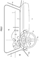
- FIG. 2 a perspective view showing a vehicle interior structure according to a first embodiment of the present invention.
- FIG. 3 is a diagram showing a visual line of a driver seated in a driver seat.
- an instrument panel 2 As shown in FIG. 2 , in the vehicle interior structure 1 according to this embodiment, as a vehicle interior structural component, an instrument panel 2, a steering wheel 4, an instrument cluster 6, a front pillar 8, a front window 10, a side window 12, etc., come into the field-of-view of the driver.
- a region of the instrument panel 2 located just above the instrument cluster 6 is formed as a raised portion which makes up an instrument cluster hood 14.
- the vehicle interior structure 1 is configured such that a lower edge 12a of a window frame of a driver seat-side side window 12 as the vehicle interior structural component is approximately coincident with an axis line Ab oriented from a vanishing point P toward a vehicle interior. More specifically, an inclination of the lower edge 12a of the window frame of the driver seat-side side window 12 through which a driver seated in a driver seat visually views forwardly is approximately coincident with an inclination of the axis line Ab oriented from the vanishing point P toward the vehicle interior.
- the instrument panel (dashboard) 2 is maximally raised in a region formed as the instrument cluster hood 14.
- the instrument cluster hood 14 is formed such that the curvature radius thereof is reduced at a vehicle width-directional mid top thereof, to form a protrusion 14a protruding upwardly.
- This protrusion 14a is located on an axis line Ac extending to the driver from the vanishing point defined when the driver visually views forwardly while being seated in the driver seat, to function as a vanishing point mark.
- a straight line connecting the protrusion 14a and a center point 4a of the steering wheel 4 is parallel to a longitudinal (forward-rearward directional) axis of the vehicle, wherein this straight line is approximately coincident with the axis line Ac extending to the driver from the vanishing point defined when the driver visually views forwardly while being seated in the driver seat.
- the protrusion 14a of the instrument cluster hood 14 provided at an upper end of the instrument panel 2 is located above an upper end 4b of the steering wheel 4 when viewed from the driver seated in the driver seat.
- the protrusion 14a serving as the vanishing point mark always comes into the field-of-view of the driver during driving of the vehicle, so that attention of the driver is strongly directed toward the protrusion 14a.
- the visual line of the driver is more likely to be guided to the the protrusion 14a.
- the driver becomes more likely to strongly direct attention toward the axis line Ac extending from the vanishing point P to the driver, so that it becomes easier for the driver to figure out the position of the own vehicle in a traveling lane.
- a visual line of a driver who drives a vehicle while being seated in a driver seat becomes different depending on the height position of the eyes of the driver, as shown in FIG. 3 .
- the height position of the eyes of a driver is determined on the basis of a driver model using AM50 (which is a human body model made mainly based on average values of adult males including American adult males by 50%; body height: 175 cm, body weight: 78 kg), and each vehicle interior structural component is designed.
- AM50 which is a human body model made mainly based on average values of adult males including American adult males by 50%; body height: 175 cm, body weight: 78 kg
- the vehicle interior structure 1 is configured such that the lower edge 12a of the window frame of the side window 12 is approximately coincident with the axis line Ab oriented from the vanishing point P toward the vehicle interior, so that the axis line Ab extending from the vanishing point is approximately coincident with the outline of the lower edge 12a of the window frame of the side window 12 as the vehicle interior structural component over a relatively long distance, and thereby it is possible to effectively assist the "axis feeling" of the driver.
- the upper end of the instrument panel 2 is provided with the protrusion 14a serving as the vanishing point mark at a position on the axis line extending to the driver from the vanishing point P defined when the driver visually views forwardly, so that the driver can easily recognize the vanishing point P.
- the driver becomes more likely to direct attention toward the axis line Ac extending from the vanishing point P to the driver. This makes it possible for the driver to easily figure out his/her position in the space where the vehicle travels and to easily drive the vehicle to travel along an appropriate zone in a traveling lane.
- the vanishing point mark is composed of the protrusion 14a provided in the instrument panel, so that it impossible to provide the vanishing point mark at a given position without spoiling aesthetic quality of the vehicle interior structure.
- the protrusion 14a provided in the instrument panel 2 is provided in the top of the instrument cluster hood 14, so that the protrusion 14a serving as the mark of the vanishing point P is located at an approximately center of the field-of-view of the driver.
- the driver is apt to naturally look at the protrusion 14a, so that it is possible for the driver to effectively direct attention toward the axis line Ac extending from the vanishing point P.
- the protrusion 14a serving as the vanishing point mark is located above the upper end of the steering wheel 4 of the vehicle when viewed from the driver seated in the driver seat of the vehicle, so that it is possible to allow the vanishing point mark to always come into the driver's field-of-view together with an external landscape, thereby always prompting the driver to direct attention toward the vanishing point.
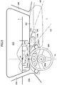
- FIG. 4 is a perspective view showing the vehicle interior structure according to the second embodiment.
- an instrument panel 102, a steering wheel 104, an instrument cluster 106, a front pillar 108, a front window 110, a side window 112, etc. come into the field-of-view of a driver.
- a region of the instrument panel 102 located just above the instrument cluster 106 is formed as a raised portion which makes up an instrument cluster hood 114.
- the vehicle interior structure 100 is configured such that two ridge lines on opposite sides of the instrument cluster hood 114 of the instrument panel 102 as the vehicle interior structural component are approximately coincident, respectively, with two axis lines Af each oriented from a vanishing point P toward a vehicle interior.
- the raised portion forming the instrument cluster hood 114 has two inclined surfaces on opposite sides thereof, wherein each of the inclined surfaces is partly formed linearly. Then, an inclination of each of two ridge lines 114a linearly extending in an inverted V shape is approximately coincident with an inclination of a corresponding one of the two axis lines Af oriented from the vanishing point P toward the vehicle interior.
- each of the ridge lines 114a of the outline the instrument cluster hood 114 to be approximately coincident with a corresponding one of the two axis lines Af oriented from the vanishing point P toward the vehicle interior, it becomes easier for the driver to obtain the "axis feeling", and adequately figure out the position of an own vehicle in a space where the vehicle travels.
- the instrument panel (dashboard) 102 is maximally raised in a region formed as the instrument cluster hood 114.
- the instrument cluster hood 114 is formed with a recess 114 at a vehicle width-directional mid top thereof. This recess 114a is located on an axis line Ac extending to the driver from the vanishing point defined when the driver visually views forwardly while being seated in the driver seat, to function as a vanishing point mark.
- a straight line connecting the recess 114a and a center point 104a of the steering wheel 104 is parallel to a longitudinal axis of the vehicle, wherein this straight line is approximately coincident with the axis line Ac extending to the driver from the vanishing point defined when the driver visually views forwardly.
- the mid recess 114a of the instrument cluster hood 114 provided at an upper end of the instrument panel 102 is located above an upper end 104b of the steering wheel 104 when viewed from the driver seated in the driver seat.
- the recess 114a serving as the vanishing point mark always comes into the field-of-view of the driver during driving of the vehicle, so that attention of the driver is strongly directed toward the recess 114a.
- the visual line of the driver is more likely to be guided to the the recess 114a.
- the driver becomes more likely to strongly direct attention toward the axis line Ac extending from the vanishing point P to the driver, so that it becomes easier for the driver to figure out the position of the own vehicle in a traveling lane.
- the height position of the eyes of a driver is determined on the basis of a driver model using AM50 as a human body model, and each vehicle interior component is designed.
- the vehicle interior structure 100 is configured such that each of the ridge lines 114a as a given region of the outer edge of the instrument cluster hood 114 is approximately coincident with a corresponding one of the axis lines Af oriented from the vanishing point P toward the vehicle interior, so that the "axis feeling" is assisted in the vicinity of the center of the field-of-view of the driver, and thereby it is possible to effectively assist the "axis feeling" of the driver.
- the upper end of the instrument panel 102 is provided with the recess 114a serving as the vanishing point mark at a position on the axis line extending to the driver from the vanishing point P defined when the driver visually views forwardly, so that the driver can easily recognize the vanishing point P.
- FIG. 6 is a perspective view showing the vehicle interior structure according to the third embodiment.
- an instrument panel 202, a steering wheel 204, an instrument cluster 206, a front pillar 208, a front window 210, a side window 212, a center display 216, etc. come into the field-of-view of a driver.
- a region of the instrument panel 202 located just above the instrument cluster 206 is formed as a raised portion which makes up an instrument cluster hood 214.
- the center display 216 serving as the vehicle interior structural component is a display device arranged on the instrument panel 202 at a vehicle width-directional central position to display information about the vehicle, map information, traffic information and others.
- a body of the center display 216 is formed in a trapezoidal shape, wherein opposite lateral edges 216a thereof are inclined to face toward the side of a driver seat.
- the body of the center display 216 is formed in a trapezoidal shape having upper and bottom sides parallel to each other, and two lateral sides inclined in the same direction, wherein the two lateral sides form the opposite lateral edges 216a. Further, in the two lateral sides, one inner side closer to the driver seat has a steeper inclination, and another outer side (farther from the driver seat) has a moderate inclination as compared with the inner side. In this way, each of the lateral edges 216a of the center display 216 is oriented such that it is coincident with a corresponding one of two axis lines Ad oriented from a vanishing point P toward a vehicle interior.
- each of the lateral edges 216a of the center display 216 to be approximately coincident with a corresponding one of the two axis lines Ad oriented from the vanishing point P toward the vehicle interior, it becomes easier for the driver to obtain the "axis feeling", and adequately figure out the position of an own vehicle in a space where the vehicle travels.
- the center display 216 comprises a rectangular liquid crystal display 216b provided in a central region of the body thereof and configured to display a variety of information thereon.
- the center display 216 also comprises a camera lens 218 provided in a space between the liquid crystal display 216b and the edge 216a closer to the driver seat to monitor the driver.
- the center display 216 further comprises an LED (light-emitting diode) provided in a space between the liquid crystal display 216b and the edge 216a farther from the driver seat to illuminate the driver and the vehicle interior. That is, in a front surface of the center display 216, the camera lens 218 is arranged on the upper side of one lateral region thereof closer to the driver seat, and the LED 220 is arranged on the lower side of another lateral region thereof farther from the driver seat.
- the instrument panel (dashboard) 202 is maximally raised in a region formed as the instrument cluster hood 214.
- the instrument cluster hood 214 is formed with a marked spot 214 at a vehicle width-directional mid top thereof, wherein the marked spot 214a is formed in a color different from that of the surround.
- This marked spot 214a is located on an axis line Ac extending to the driver from the vanishing point defined when the driver visually views forwardly while being seated in the driver seat, to function as a vanishing point mark.
- a straight line connecting the marked spot 214a and a center point 204a of the steering wheel 204 is parallel to a longitudinal axis of the vehicle, wherein this straight line is approximately coincident with the axis line Ac extending to the driver from the vanishing point defined when the driver visually views forwardly.
- the mid marked spot 214a of the instrument cluster hood 214 provided at an upper end of the instrument panel 202 is located above an upper end 204b of the steering wheel 204 when viewed from the driver seated in the driver seat.
- the marked spot 214a serving as the vanishing point mark always comes into the field-of-view of the driver during driving of the vehicle, so that attention of the driver is strongly directed toward the marked spot 214a.
- the visual line of the driver is more likely to be guided to the the marked spot 214a.
- the driver becomes more likely to strongly direct attention toward the axis line Ac extending from the vanishing point P to the driver, so that it becomes easier for the driver to figure out the position of the own vehicle in a traveling lane.
- the height position of the eyes of a driver is determined on the basis of a driver model using AM50 as a human body model, and each vehicle interior component is designed.
- the upper end of the instrument panel 202 is provided with the marked spot 214a serving as the vanishing point mark at a position on the axis line extending to the driver from the vanishing point P defined when the driver visually views forwardly, so that the driver can easily recognize the vanishing point P.
- each of the opposite lateral edges 214a of the center display 216 is approximately coincident with a corresponding one of the axis lines Ad oriented from the vanishing point P toward the vehicle interior, so that an outline for assisting the "axis feeling" can be arranged in a vehicle width-directional center side of the vehicle, and thereby it becomes possible for the driver to obtain a more accurate axis feeling.
Landscapes
- Engineering & Computer Science (AREA)
- Mechanical Engineering (AREA)
- Chemical & Material Sciences (AREA)
- Combustion & Propulsion (AREA)
- Transportation (AREA)
- Instrument Panels (AREA)
- Fittings On The Vehicle Exterior For Carrying Loads, And Devices For Holding Or Mounting Articles (AREA)
Claims (9)
- Innenraumanordnung für ein Fahrzeug, welche aufweist:eine Fahrzeuginnenraumanordnungskomponente, die in einem Sichtfeld eines Fahrers angeordnet ist,wobei sich ein Mittelpunkt (4a) eines Lenkrads (4, 104, 204) und eine mittige Oberseite einer Kombiinstrumentenabdeckung (14, 114, 214), die beide einen Teil der Innenraumanordnung bilden und dazu konfiguriert sind, in einem Fahrzeuginnenraum angeordnet zu sein, in einer Projektionsebene aus Sicht des Fahrers auf einer Achsenlinie befinden, die sich von einem Fluchtpunkt (P), der definiert ist, wenn der Fahrer beim Sitzen im Fahrersitz visuell nach vorne blickt, zum Fahrer erstreckt, während das Fahrzeug auf einer ebenen und geraden Spur fährt,
dadurch gekennzeichnet, dassein Umriss eines Seitenfensters (12, 112, 212), der Kombiinstrumentenabdeckung (14, 114, 214) und/oder eines Hauptteils der Mittelanzeige (216), die dazu konfiguriert ist, auf einem Armaturenbrett (2, 102, 202) des Fahrzeugs angeordnet zu sein, das als die Fahrzeuginnenraumanordnungskomponente dient, mit einer Achsenlinie zusammenfällt, die zum Fahrzeuginnenraum hin ausgerichtet ist, unter mehreren Achsenlinien, die sich von dem Fluchtpunkt (P) aus radial erstrecken, undwenigstens ein Umriss der Fahrzeuginnenraumanordnungskomponente visuell von dem Fahrer gesehen werden kann, sodass er in einem vorwärts gerichteten Sichtfeld des im Fahrersitz sitzenden Fahrers mit der Achsenlinie, die von dem Fluchtpunkt (P) zum Fahrzeuginnenraum hin ausgerichtet ist, zusammenfällt. - Innenraumanordnung nach Anspruch 1, wobei die Fahrzeuginnenraumanordnungskomponente ein Fensterrahmen des Seitenfensters (12, 112, 212) ist und wobei die Innenraumanordnung derart konfiguriert ist, dass eine Unterkante (12a) des Fensterrahmens annähernd mit der Achsenlinie, die von dem Fluchtpunkt (P) zum Fahrzeuginnenraum hin ausgerichtet ist, zusammenfällt.
- Innenraumanordnung nach Anspruch 1, wobei die Fahrzeuginnenraumanordnungskomponente die Mittelanzeige (216) ist, die auf einem Armaturenbrett (202) des Fahrzeugs angeordnet ist, und wobei die Innenraumanordnung derart konfiguriert ist, dass jede von einander gegenüberliegenden Seitenkanten eines Hauptteils der Mittelanzeige (216) annähernd mit der Achsenlinie, die von dem Fluchtpunkt (P) zum Fahrzeuginnenraum hin ausgerichtet ist, zusammenfällt.
- Innenraumanordnung nach Anspruch 1, wobei die Fahrzeuginnenraumanordnungskomponente eine Kombiinstrumentenabdeckung (14, 114, 214) ist und wobei die Innenraumanordnung derart konfiguriert ist, dass ein vorgegebener Bereich einer Außenkante der Kombiinstrumentenabdeckung (14, 114, 214) annähernd mit der Achsenlinie, die von dem Fluchtpunkt (P) zum Fahrzeuginnenraum hin ausgerichtet ist, zusammenfällt.
- Innenraumanordnung nach einem der Ansprüche 1 bis 4, wobei ein oberes Ende eines Armaturenbretts (2, 102, 202), das vor dem Fahrersitz angeordnet ist, um als die Fahrzeuginnenraumanordnungskomponente zu dienen, an einer Position auf der Achsenlinie, die sich vom Fluchtpunkt (P), der definiert ist, wenn der Fahrer beim Sitzen im Fahrersitz visuell nach vorne blickt, zum Fahrer erstreckt, mit einer Fluchtpunktmarkierung (14a, 114b, 214a) versehen ist.
- Innenraumanordnung nach Anspruch 5, wobei die Fluchtpunktmarkierung, die auf dem oberen Ende des Armaturenbretts (2) ausgebildet ist, ein auf dem Armaturenbrett ausgebildeter Vorsprung (14a) ist.
- Innenraumanordnung nach Anspruch 6, wobei der Vorsprung (14a), der auf dem Armaturenbrett (2) ausgebildet ist, auf einer Oberseite einer Kombiinstrumentenabdeckung (14) des Armaturenbretts (2) bereitgestellt ist.
- Innenraumanordnung nach einem der Ansprüche 5 bis 7, wobei sich die Fluchtpunktmarkierung (14a, 114b, 214a), die auf dem oberen Ende des Armaturenbretts (2, 102, 202) ausgebildet ist, über einem oberen Ende des Lenkrads (4, 104, 204) des Fahrzeugs aus Sicht des im Fahrersitz des Fahrzeugs sitzenden Fahrers befindet.
- Innenraumanordnung nach einem der Ansprüche 5 bis 8, wobei Umrisse beider Seiten (114a) einer Oberseite der Kombiinstrumentenabdeckung (114) jeweils mit zwei Achsenlinien zusammenfallen, die zum Fahrzeuginnenraum hin ausgerichtet sind, unter den Achsenlinien, die sich von dem Fluchtpunkt (P) aus radial erstrecken, der definiert ist, wenn der Fahrer beim Sitzen im Fahrersitz visuell nach vorne blickt.
Applications Claiming Priority (3)
| Application Number | Priority Date | Filing Date | Title |
|---|---|---|---|
| JP2017162402A JP6575935B2 (ja) | 2017-08-25 | 2017-08-25 | 車室内構造 |
| JP2017162403A JP6575936B2 (ja) | 2017-08-25 | 2017-08-25 | 車室内構造 |
| PCT/JP2018/030553 WO2019039406A1 (ja) | 2017-08-25 | 2018-08-17 | 車室内構造 |
Publications (3)
| Publication Number | Publication Date |
|---|---|
| EP3659849A1 EP3659849A1 (de) | 2020-06-03 |
| EP3659849A4 EP3659849A4 (de) | 2020-08-12 |
| EP3659849B1 true EP3659849B1 (de) | 2021-09-29 |
Family
ID=65438714
Family Applications (1)
| Application Number | Title | Priority Date | Filing Date |
|---|---|---|---|
| EP18847426.6A Active EP3659849B1 (de) | 2017-08-25 | 2018-08-17 | Fahrgastraumstruktur |
Country Status (4)
| Country | Link |
|---|---|
| US (1) | US11465503B2 (de) |
| EP (1) | EP3659849B1 (de) |
| CN (1) | CN111065538B (de) |
| WO (1) | WO2019039406A1 (de) |
Families Citing this family (2)
| Publication number | Priority date | Publication date | Assignee | Title |
|---|---|---|---|---|
| JP6949085B2 (ja) * | 2019-10-21 | 2021-10-13 | 本田技研工業株式会社 | フロントピラートリムとインストルメントパネルとの合わせ構造 |
| KR102866419B1 (ko) * | 2020-07-08 | 2025-10-01 | 현대모비스 주식회사 | 3d 이미지를 이용한 클러스터 정보 제공 장치 및 그 방법 |
Family Cites Families (8)
| Publication number | Priority date | Publication date | Assignee | Title |
|---|---|---|---|---|
| JP2004203130A (ja) * | 2002-12-24 | 2004-07-22 | Shimizu Home Techno Kk | 車両感覚表示マーク技術 |
| JP5001753B2 (ja) * | 2007-02-15 | 2012-08-15 | 本田技研工業株式会社 | 車両用フロントウィンドウ |
| JP6233599B2 (ja) | 2014-02-25 | 2017-11-22 | マツダ株式会社 | 車両用表示制御装置 |
| JP6164152B2 (ja) | 2014-05-20 | 2017-07-19 | マツダ株式会社 | 自動車の窓枠構造 |
| JP6152840B2 (ja) | 2014-10-27 | 2017-06-28 | マツダ株式会社 | 車両の視界調整装置 |
| JP6197814B2 (ja) * | 2015-03-18 | 2017-09-20 | マツダ株式会社 | 車両用表示装置 |
| JP2017056909A (ja) * | 2015-09-18 | 2017-03-23 | マツダ株式会社 | 車両用画像表示装置 |
| JP6558228B2 (ja) | 2015-11-30 | 2019-08-14 | 株式会社Jvcケンウッド | ヘッドライト装置、ヘッドライト制御方法およびヘッドライト制御プログラム |
-
2018
- 2018-08-17 US US16/641,624 patent/US11465503B2/en active Active
- 2018-08-17 WO PCT/JP2018/030553 patent/WO2019039406A1/ja not_active Ceased
- 2018-08-17 EP EP18847426.6A patent/EP3659849B1/de active Active
- 2018-08-17 CN CN201880055095.3A patent/CN111065538B/zh active Active
Also Published As
| Publication number | Publication date |
|---|---|
| CN111065538A (zh) | 2020-04-24 |
| US20210031631A1 (en) | 2021-02-04 |
| EP3659849A1 (de) | 2020-06-03 |
| US11465503B2 (en) | 2022-10-11 |
| WO2019039406A1 (ja) | 2019-02-28 |
| CN111065538B (zh) | 2023-03-28 |
| EP3659849A4 (de) | 2020-08-12 |
Similar Documents
| Publication | Publication Date | Title |
|---|---|---|
| US9365163B2 (en) | Device for visually confirming forward direction | |
| EP4098469A1 (de) | Headup-anzeigevorrichtung und fahrzeug | |
| JP6152840B2 (ja) | 車両の視界調整装置 | |
| JP6684940B2 (ja) | 車両の視線誘導装置 | |
| CN101244695B (zh) | 车辆用前窗 | |
| EP3659849B1 (de) | Fahrgastraumstruktur | |
| US20070216189A1 (en) | Vehicular Body Structure | |
| JP4575275B2 (ja) | 車両用表示装置 | |
| JP6160566B2 (ja) | 車両制御装置 | |
| JP6191573B2 (ja) | 車両の視界調整装置 | |
| US8007022B2 (en) | Front window shield for vehicle | |
| JP6575935B2 (ja) | 車室内構造 | |
| JP6575936B2 (ja) | 車室内構造 | |
| JP4721683B2 (ja) | 車両の前部構造 | |
| JP7184083B2 (ja) | 車両用表示装置、車両用表示装置の制御方法、車両用表示装置の制御プログラム | |
| JP6365575B2 (ja) | 車両の室内指標表示装置 | |
| CN106467008A (zh) | 前挡风玻璃 | |
| JP2003075169A (ja) | 地図表示装置 | |
| JP6156277B2 (ja) | 自動車のインストルメントパネル構造 | |
| CN121263317A (zh) | 车辆的前挡风玻璃 | |
| JP2005035511A (ja) | 車両感覚補助装置 | |
| JP2009208536A (ja) | ウインドシールド構造 |
Legal Events
| Date | Code | Title | Description |
|---|---|---|---|
| STAA | Information on the status of an ep patent application or granted ep patent |
Free format text: STATUS: THE INTERNATIONAL PUBLICATION HAS BEEN MADE |
|
| PUAI | Public reference made under article 153(3) epc to a published international application that has entered the european phase |
Free format text: ORIGINAL CODE: 0009012 |
|
| STAA | Information on the status of an ep patent application or granted ep patent |
Free format text: STATUS: REQUEST FOR EXAMINATION WAS MADE |
|
| 17P | Request for examination filed |
Effective date: 20200224 |
|
| AK | Designated contracting states |
Kind code of ref document: A1 Designated state(s): AL AT BE BG CH CY CZ DE DK EE ES FI FR GB GR HR HU IE IS IT LI LT LU LV MC MK MT NL NO PL PT RO RS SE SI SK SM TR |
|
| AX | Request for extension of the european patent |
Extension state: BA ME |
|
| A4 | Supplementary search report drawn up and despatched |
Effective date: 20200710 |
|
| RIC1 | Information provided on ipc code assigned before grant |
Ipc: B60K 37/00 20060101AFI20200706BHEP Ipc: B60J 5/04 20060101ALI20200706BHEP |
|
| DAV | Request for validation of the european patent (deleted) | ||
| DAX | Request for extension of the european patent (deleted) | ||
| GRAP | Despatch of communication of intention to grant a patent |
Free format text: ORIGINAL CODE: EPIDOSNIGR1 |
|
| STAA | Information on the status of an ep patent application or granted ep patent |
Free format text: STATUS: GRANT OF PATENT IS INTENDED |
|
| INTG | Intention to grant announced |
Effective date: 20210414 |
|
| GRAS | Grant fee paid |
Free format text: ORIGINAL CODE: EPIDOSNIGR3 |
|
| GRAA | (expected) grant |
Free format text: ORIGINAL CODE: 0009210 |
|
| STAA | Information on the status of an ep patent application or granted ep patent |
Free format text: STATUS: THE PATENT HAS BEEN GRANTED |
|
| AK | Designated contracting states |
Kind code of ref document: B1 Designated state(s): AL AT BE BG CH CY CZ DE DK EE ES FI FR GB GR HR HU IE IS IT LI LT LU LV MC MK MT NL NO PL PT RO RS SE SI SK SM TR |
|
| REG | Reference to a national code |
Ref country code: GB Ref legal event code: FG4D |
|
| REG | Reference to a national code |
Ref country code: CH Ref legal event code: EP Ref country code: AT Ref legal event code: REF Ref document number: 1433910 Country of ref document: AT Kind code of ref document: T Effective date: 20211015 |
|
| REG | Reference to a national code |
Ref country code: DE Ref legal event code: R096 Ref document number: 602018024437 Country of ref document: DE |
|
| REG | Reference to a national code |
Ref country code: IE Ref legal event code: FG4D |
|
| REG | Reference to a national code |
Ref country code: LT Ref legal event code: MG9D |
|
| PG25 | Lapsed in a contracting state [announced via postgrant information from national office to epo] |
Ref country code: LT Free format text: LAPSE BECAUSE OF FAILURE TO SUBMIT A TRANSLATION OF THE DESCRIPTION OR TO PAY THE FEE WITHIN THE PRESCRIBED TIME-LIMIT Effective date: 20210929 Ref country code: BG Free format text: LAPSE BECAUSE OF FAILURE TO SUBMIT A TRANSLATION OF THE DESCRIPTION OR TO PAY THE FEE WITHIN THE PRESCRIBED TIME-LIMIT Effective date: 20211229 Ref country code: NO Free format text: LAPSE BECAUSE OF FAILURE TO SUBMIT A TRANSLATION OF THE DESCRIPTION OR TO PAY THE FEE WITHIN THE PRESCRIBED TIME-LIMIT Effective date: 20211229 Ref country code: HR Free format text: LAPSE BECAUSE OF FAILURE TO SUBMIT A TRANSLATION OF THE DESCRIPTION OR TO PAY THE FEE WITHIN THE PRESCRIBED TIME-LIMIT Effective date: 20210929 Ref country code: FI Free format text: LAPSE BECAUSE OF FAILURE TO SUBMIT A TRANSLATION OF THE DESCRIPTION OR TO PAY THE FEE WITHIN THE PRESCRIBED TIME-LIMIT Effective date: 20210929 Ref country code: SE Free format text: LAPSE BECAUSE OF FAILURE TO SUBMIT A TRANSLATION OF THE DESCRIPTION OR TO PAY THE FEE WITHIN THE PRESCRIBED TIME-LIMIT Effective date: 20210929 Ref country code: RS Free format text: LAPSE BECAUSE OF FAILURE TO SUBMIT A TRANSLATION OF THE DESCRIPTION OR TO PAY THE FEE WITHIN THE PRESCRIBED TIME-LIMIT Effective date: 20210929 |
|
| REG | Reference to a national code |
Ref country code: NL Ref legal event code: MP Effective date: 20210929 |
|
| REG | Reference to a national code |
Ref country code: AT Ref legal event code: MK05 Ref document number: 1433910 Country of ref document: AT Kind code of ref document: T Effective date: 20210929 |
|
| PG25 | Lapsed in a contracting state [announced via postgrant information from national office to epo] |
Ref country code: LV Free format text: LAPSE BECAUSE OF FAILURE TO SUBMIT A TRANSLATION OF THE DESCRIPTION OR TO PAY THE FEE WITHIN THE PRESCRIBED TIME-LIMIT Effective date: 20210929 Ref country code: GR Free format text: LAPSE BECAUSE OF FAILURE TO SUBMIT A TRANSLATION OF THE DESCRIPTION OR TO PAY THE FEE WITHIN THE PRESCRIBED TIME-LIMIT Effective date: 20211230 |
|
| PG25 | Lapsed in a contracting state [announced via postgrant information from national office to epo] |
Ref country code: AT Free format text: LAPSE BECAUSE OF FAILURE TO SUBMIT A TRANSLATION OF THE DESCRIPTION OR TO PAY THE FEE WITHIN THE PRESCRIBED TIME-LIMIT Effective date: 20210929 |
|
| PG25 | Lapsed in a contracting state [announced via postgrant information from national office to epo] |
Ref country code: IS Free format text: LAPSE BECAUSE OF FAILURE TO SUBMIT A TRANSLATION OF THE DESCRIPTION OR TO PAY THE FEE WITHIN THE PRESCRIBED TIME-LIMIT Effective date: 20220129 Ref country code: SK Free format text: LAPSE BECAUSE OF FAILURE TO SUBMIT A TRANSLATION OF THE DESCRIPTION OR TO PAY THE FEE WITHIN THE PRESCRIBED TIME-LIMIT Effective date: 20210929 Ref country code: RO Free format text: LAPSE BECAUSE OF FAILURE TO SUBMIT A TRANSLATION OF THE DESCRIPTION OR TO PAY THE FEE WITHIN THE PRESCRIBED TIME-LIMIT Effective date: 20210929 Ref country code: PT Free format text: LAPSE BECAUSE OF FAILURE TO SUBMIT A TRANSLATION OF THE DESCRIPTION OR TO PAY THE FEE WITHIN THE PRESCRIBED TIME-LIMIT Effective date: 20220131 Ref country code: PL Free format text: LAPSE BECAUSE OF FAILURE TO SUBMIT A TRANSLATION OF THE DESCRIPTION OR TO PAY THE FEE WITHIN THE PRESCRIBED TIME-LIMIT Effective date: 20210929 Ref country code: NL Free format text: LAPSE BECAUSE OF FAILURE TO SUBMIT A TRANSLATION OF THE DESCRIPTION OR TO PAY THE FEE WITHIN THE PRESCRIBED TIME-LIMIT Effective date: 20210929 Ref country code: ES Free format text: LAPSE BECAUSE OF FAILURE TO SUBMIT A TRANSLATION OF THE DESCRIPTION OR TO PAY THE FEE WITHIN THE PRESCRIBED TIME-LIMIT Effective date: 20210929 Ref country code: EE Free format text: LAPSE BECAUSE OF FAILURE TO SUBMIT A TRANSLATION OF THE DESCRIPTION OR TO PAY THE FEE WITHIN THE PRESCRIBED TIME-LIMIT Effective date: 20210929 Ref country code: CZ Free format text: LAPSE BECAUSE OF FAILURE TO SUBMIT A TRANSLATION OF THE DESCRIPTION OR TO PAY THE FEE WITHIN THE PRESCRIBED TIME-LIMIT Effective date: 20210929 Ref country code: AL Free format text: LAPSE BECAUSE OF FAILURE TO SUBMIT A TRANSLATION OF THE DESCRIPTION OR TO PAY THE FEE WITHIN THE PRESCRIBED TIME-LIMIT Effective date: 20210929 |
|
| REG | Reference to a national code |
Ref country code: DE Ref legal event code: R097 Ref document number: 602018024437 Country of ref document: DE |
|
| PG25 | Lapsed in a contracting state [announced via postgrant information from national office to epo] |
Ref country code: DK Free format text: LAPSE BECAUSE OF FAILURE TO SUBMIT A TRANSLATION OF THE DESCRIPTION OR TO PAY THE FEE WITHIN THE PRESCRIBED TIME-LIMIT Effective date: 20210929 |
|
| PLBE | No opposition filed within time limit |
Free format text: ORIGINAL CODE: 0009261 |
|
| STAA | Information on the status of an ep patent application or granted ep patent |
Free format text: STATUS: NO OPPOSITION FILED WITHIN TIME LIMIT |
|
| 26N | No opposition filed |
Effective date: 20220630 |
|
| PG25 | Lapsed in a contracting state [announced via postgrant information from national office to epo] |
Ref country code: SI Free format text: LAPSE BECAUSE OF FAILURE TO SUBMIT A TRANSLATION OF THE DESCRIPTION OR TO PAY THE FEE WITHIN THE PRESCRIBED TIME-LIMIT Effective date: 20210929 |
|
| PG25 | Lapsed in a contracting state [announced via postgrant information from national office to epo] |
Ref country code: IT Free format text: LAPSE BECAUSE OF FAILURE TO SUBMIT A TRANSLATION OF THE DESCRIPTION OR TO PAY THE FEE WITHIN THE PRESCRIBED TIME-LIMIT Effective date: 20210929 |
|
| PG25 | Lapsed in a contracting state [announced via postgrant information from national office to epo] |
Ref country code: MC Free format text: LAPSE BECAUSE OF FAILURE TO SUBMIT A TRANSLATION OF THE DESCRIPTION OR TO PAY THE FEE WITHIN THE PRESCRIBED TIME-LIMIT Effective date: 20210929 |
|
| REG | Reference to a national code |
Ref country code: CH Ref legal event code: PL |
|
| GBPC | Gb: european patent ceased through non-payment of renewal fee |
Effective date: 20220817 |
|
| PG25 | Lapsed in a contracting state [announced via postgrant information from national office to epo] |
Ref country code: LU Free format text: LAPSE BECAUSE OF NON-PAYMENT OF DUE FEES Effective date: 20220817 Ref country code: LI Free format text: LAPSE BECAUSE OF NON-PAYMENT OF DUE FEES Effective date: 20220831 Ref country code: CH Free format text: LAPSE BECAUSE OF NON-PAYMENT OF DUE FEES Effective date: 20220831 |
|
| REG | Reference to a national code |
Ref country code: BE Ref legal event code: MM Effective date: 20220831 |
|
| PG25 | Lapsed in a contracting state [announced via postgrant information from national office to epo] |
Ref country code: IE Free format text: LAPSE BECAUSE OF NON-PAYMENT OF DUE FEES Effective date: 20220817 Ref country code: FR Free format text: LAPSE BECAUSE OF NON-PAYMENT OF DUE FEES Effective date: 20220831 |
|
| PG25 | Lapsed in a contracting state [announced via postgrant information from national office to epo] |
Ref country code: BE Free format text: LAPSE BECAUSE OF NON-PAYMENT OF DUE FEES Effective date: 20220831 |
|
| PG25 | Lapsed in a contracting state [announced via postgrant information from national office to epo] |
Ref country code: GB Free format text: LAPSE BECAUSE OF NON-PAYMENT OF DUE FEES Effective date: 20220817 |
|
| PG25 | Lapsed in a contracting state [announced via postgrant information from national office to epo] |
Ref country code: SM Free format text: LAPSE BECAUSE OF FAILURE TO SUBMIT A TRANSLATION OF THE DESCRIPTION OR TO PAY THE FEE WITHIN THE PRESCRIBED TIME-LIMIT Effective date: 20210929 Ref country code: CY Free format text: LAPSE BECAUSE OF FAILURE TO SUBMIT A TRANSLATION OF THE DESCRIPTION OR TO PAY THE FEE WITHIN THE PRESCRIBED TIME-LIMIT Effective date: 20210929 |
|
| PG25 | Lapsed in a contracting state [announced via postgrant information from national office to epo] |
Ref country code: MK Free format text: LAPSE BECAUSE OF FAILURE TO SUBMIT A TRANSLATION OF THE DESCRIPTION OR TO PAY THE FEE WITHIN THE PRESCRIBED TIME-LIMIT Effective date: 20210929 Ref country code: HU Free format text: LAPSE BECAUSE OF FAILURE TO SUBMIT A TRANSLATION OF THE DESCRIPTION OR TO PAY THE FEE WITHIN THE PRESCRIBED TIME-LIMIT; INVALID AB INITIO Effective date: 20180817 |
|
| PG25 | Lapsed in a contracting state [announced via postgrant information from national office to epo] |
Ref country code: MT Free format text: LAPSE BECAUSE OF FAILURE TO SUBMIT A TRANSLATION OF THE DESCRIPTION OR TO PAY THE FEE WITHIN THE PRESCRIBED TIME-LIMIT Effective date: 20210929 |
|
| PGFP | Annual fee paid to national office [announced via postgrant information from national office to epo] |
Ref country code: DE Payment date: 20250702 Year of fee payment: 8 |
|
| PG25 | Lapsed in a contracting state [announced via postgrant information from national office to epo] |
Ref country code: TR Free format text: LAPSE BECAUSE OF FAILURE TO SUBMIT A TRANSLATION OF THE DESCRIPTION OR TO PAY THE FEE WITHIN THE PRESCRIBED TIME-LIMIT Effective date: 20210929 |