EP3659867A1 - Verfahren zur herstellung eines retroreflektierenden kfz-kennzeichenschilds, retroreflektierendes kfz-kennzeichenschild sowie vorrichtung zur durchführung des verfahrens - Google Patents
Verfahren zur herstellung eines retroreflektierenden kfz-kennzeichenschilds, retroreflektierendes kfz-kennzeichenschild sowie vorrichtung zur durchführung des verfahrens Download PDFInfo
- Publication number
- EP3659867A1 EP3659867A1 EP19219268.0A EP19219268A EP3659867A1 EP 3659867 A1 EP3659867 A1 EP 3659867A1 EP 19219268 A EP19219268 A EP 19219268A EP 3659867 A1 EP3659867 A1 EP 3659867A1
- Authority
- EP
- European Patent Office
- Prior art keywords
- blank
- license plate
- shield
- vehicle license
- motor vehicle
- Prior art date
- Legal status (The legal status is an assumption and is not a legal conclusion. Google has not performed a legal analysis and makes no representation as to the accuracy of the status listed.)
- Withdrawn
Links
Images


Classifications
-
- B—PERFORMING OPERATIONS; TRANSPORTING
- B60—VEHICLES IN GENERAL
- B60R—VEHICLES, VEHICLE FITTINGS, OR VEHICLE PARTS, NOT OTHERWISE PROVIDED FOR
- B60R13/00—Elements for body-finishing, identifying, or decorating; Arrangements or adaptations for advertising purposes
- B60R13/10—Registration, licensing, or like devices
Definitions
- the present invention relates to a method for producing a retroreflective motor vehicle license plate, a retroreflective motor vehicle license plate that can be produced according to the method and a device for carrying out the method.
- the invention relates to a production method for a motor vehicle license plate with novel security features, a device suitable for carrying out this method for producing a motor vehicle license plate with novel security features, and a motor vehicle license plate with novel security features.
- An Ensure TM security feature is an optical marking of the film that is only visible when the film is oriented vertically at a viewing angle of approximately 30 ° to the horizontal. Otherwise the film appears uniformly retroreflective, ie the security feature is invisible.
- a method for producing the Ensure TM Image security feature is described, for example, in US 4,691,993 A or in the EP 0 203 752 B1 described.
- the Ensure TM Image security feature is realized by targeted local damage to the metallic reflection layer contained in the retroreflective film by means of laser radiation. It therefore presupposes the existence of a dedicated metallic reflective layer in the retroreflective sheeting ahead and therefore cannot be inserted into retroreflective foils based on embedded microprisms.
- a retroreflective sheeting is marketed under the name Ensure TM Virtual Security Thread, which includes an optically perceptible security feature that is incorporated into the material of the sheeting and appears three-dimensional. It includes two virtual images, one of which appears to float above the plane of the shield and one below. When viewed directly from the film, it is also visible from a greater distance and can also be combined with the Ensure TM Image security feature. Further information on retroreflective foils with the Ensure TM Virtual Security Thread security feature can also be found in the EP 1 602 946 B1 . The Ensure TM Virtual Security Thread security feature can also only be incorporated into retroreflective foils with embedded microlenses and a metallic reflective layer.
- the Ensure TM Virtual Security Thread security feature can only be introduced during film production.
- a change in the security feature, e.g. its contour is therefore reserved for the film manufacturer, which makes the procurement of smaller quantities of film with a security feature individualized on customer request problematic and in particular cost-intensive.
- optical hologram seals as a security feature is known, which are produced in a separate manufacturing process on a separate carrier film.
- the Leonhard Kurz Foundation & Co.KG offers so-called hologram sealing foils, which comprise a polyester carrier, on which a lacquer package consisting of an adhesive layer, a structured metallization to form the optical hologram seal, a replication layer and a protective lacquer is removably arranged.
- these hologram seals are transferred from the polyester film to the surface of the license plate using a thermal transfer process and thermally welded to the surface thereof.
- Optical hologram seals of this type can be easily verified optically and are in particular also on retroreflective foils without metallic ones Reflective layer can be attached, for example on retroreflective foils based on microprismatic elements.
- attaching them to the license plate is technically complex and therefore increases the production costs of the license plate.
- the polyester carrier of the seal adheres in some areas to the surface of the license plate after the seal has been transferred to the surface of the license plate, so that a device is required which detaches the polyester carrier from the license plate again. There is also the risk of mechanical damage to the surface of the license plate.
- hologram seals are naturally non-transparent because of the metal layer contained therein, which in particular in the case of retroreflective license plate signs leads to local areas with a lack of retroreflectivity, which can be undesirable or even inadmissible according to local approval regulations.
- production of holograms customized according to customer requirements is expensive, since a master for hologram production is required for each individual motif, which is complex to produce. The creation of small series is therefore generally forbidden for reasons of cost.
- the object of the present invention is therefore to provide an inexpensive method for producing a license plate with an integrated security feature, which is inexpensive and avoids the aforementioned disadvantages. Furthermore, it is an object of the present invention to provide an advantageous license plate with an integrated security feature and one for Execution of the method according to the invention to specify a suitable device, which is therefore also suitable for producing a license plate according to the invention.
- This object is achieved by a manufacturing method for a license plate according to claim 1, a license plate according to claim 2 and a manufacturing device according to claim 13.
- the method according to the invention can often be integrated in the form of a few additional method steps directly into existing method sequences for the production of motor vehicle license plates, without requiring changes to these method sequences.
- the vehicle license plates produced by the method have a novel, optically perceptible security feature, which is based on an optically perceptible, extensively extended security structure, which is incorporated into the front surface of the blank plate and on regular, raised or recessed structures in the surface of the blank plate is based.
- These license plates therefore offer a high level of protection against counterfeiting, since the security structure forming the security feature is integrally connected to the material of the license plate blank, in particular here to the label plate or to a plastic film laminated thereon.
- a method according to the invention is provided for the production of a license plate.
- it comprises the step of providing a blank shield, e.g. a shield plate made of plastic or a metallic shield plate with laminated colored plastic film.
- a blank plate can already be a ready-to-use vehicle license plate, which is only provided with the security structure according to the invention within the scope of the method according to the invention.
- an optically perceptible, in particular extensive security structure is now introduced into the front surface of the shield blank in a suitable manner.
- This should include processes that either locally deform the material of the shield blank on its front surface or remove it locally.
- This formulation should not explicitly include processes in which additional material is applied to the front surface of the shield blank.
- This security structure introduced according to the invention comprises extensive, regular, raised or recessed structures in the surface of the shield blank, which are designed in such a way that the security structure introduced has an optical effect based on optical interference, in particular a color effect.
- the regular distances between the structures introduced are therefore advantageously of the order of magnitude of the wavelength of visible light, in particular in the range between 150 nanometers and 30 micrometers, particularly preferably between 450 and 1500 nanometers.
- the dominant structure size of the introduced microstructure can be tailored to customer needs within the above-mentioned framework.
- microstructures can be created that are under certain Reflect angles through constructive interference in the visible range and are therefore directly perceptible as colored images with the human eye.
- microstructures can also be generated which reflect in wavelength ranges which are invisible to the human eye, for example in the UV or in the near IR. Structures of this type are predestined for machine authenticity checking.
- the shield blank has retroreflective properties. These retroreflective properties are particularly preferably based on (micro) prismatic elements embedded in the shield blank or formed integrally therewith.
- the shield blank has an additional optically perceptible security feature which is embedded in the material of the shield blank.
- This can be, for example, the aforementioned security features, which 3M offers under the names Ensure TM Image or Ensure TM Virtual Security Thread.
- the shield blank comprises e.g. metallic shield plate, which is laminated with a retroreflective foil from 3M of one of the types 4750E or 4750T, i.e. such a film is laminated onto the front surface of the shield plate.
- the security feature according to the invention Since the security feature according to the invention only shows constructive interference at certain angles and thus only appears to the observer as a colored structure at certain angles, the security feature according to the invention is essentially invisible or transparent when viewed vertically onto the blank plate (or the ready-to-use license plate). Becomes If it is formed in or on the surface of a transparent layer, which can consist, for example, of a plastic, optically perceptible properties of the film or of the shield blank, such as additional security features embedded in the film or retroreflectivity, are largely retained through the transparent layer. In particular, this means that it is possible to design the security structure according to the invention over a large area, in particular so large that the security structure extends essentially over the entire surface of the shield blank. This represents a particular advantage of the security structure according to the invention and thus of a license plate equipped with such a license plate.
- the blank plate is provided with an individual license plate legend, e.g. can be printed on the front surface.
- the label legend can also be embossed in the shield blank when using an embossable material for the shield blank, e.g. as a raised imprint.
- An embossed license plate legend can also be colored, which is possible in particular by means of transfer from a hot stamping foil in a thermal transfer process or by rolling with an ink roller.
- a label legend can also be formed by attaching separately formed individual characters on the front surface of the blank plate.
- a vehicle license plate is basically understood to be a label which is already provided with an individual license plate legend.
- a license plate blank is understood to be a label that has not yet been provided with an individual license plate legend.
- the security structure according to the invention can be introduced into the front surface both on a blank plate and on a ready-to-use vehicle license plate that is individualized with a label legend.
- the optically perceptible security structure can be introduced into the film both before and after the film is laminated on.
- the film can advantageously be colored, e.g. to comply with national approval regulations.
- the film which is laminated onto the shield plate has retroreflective properties.
- it can be a film with microlenses embedded in a transparent plastic layer and a reflection layer behind it, or a film with microprismatic elements embedded in a transparent plastic layer.
- a further transparent layer can be placed above the microlenses or the microprismatic elements, e.g. be arranged from a suitable plastic.
- the film which is laminated onto the shield plate can be equipped with additional security features which are particularly suitable for a visual or visual inspection.
- the film can be equipped with the Ensure TM Image and / or Ensure Ensure TM Virtual Security Thread security features offered by 3M. But also films from other film manufacturers that have alternative security features, can be used advantageously.
- the film to be laminated or already laminated is equipped by the user of the method according to the invention with additional, advantageously optically recognizable security features, for example according to the teaching of the aforementioned US 4,691,993 A .
- the method described there is based on laser treatment of a retroreflective film with embedded microlenses and can advantageously also be integrated into the course of the method according to the invention.
- the optically perceptible security structure is transferred from a structured stamp or a structured roller into the front surface of the shield blank by means of mechanical stamping, in particular by means of hot stamping.
- the punch or the roller can in particular be made of a metal, preferably a suitable steel, in particular stainless steel, or also of a suitable ceramic material.
- Nickel has also proven particularly useful, particularly in the manufacture of sleeves, i.e. of sleeve-like embossing forms, which i.A. are intended to be pushed onto embossing rollers.
- coated metallic materials are fundamentally accessible to microstructuring and can therefore be used for stamping dies or rollers in the process according to the invention. To simplify matters, only stamps are used in the following. However, this wording should also explicitly include embossing rollers and sleeves.
- the preferred temperature range for hot stamping is largely determined by the materials used for the shield blank. Typical hot stamping temperatures are between 70 ° C and 180 ° C, with temperatures around 150 ° C being preferred. The latter temperatures have proven particularly useful when embossing shield blanks, which comprise a plastic film laminated onto a shield plate. This temperature is particularly advantageous when using commercially available retroreflective films for the Vehicle license plate production, such as those offered by manufacturers 3M, Avery and Orafol.
- Typical embossing pressures are a maximum of 10 tons with an embossing area of 20 x 20 mm 2 , but generally lower pressures in the range of 1 to 2 tons are sufficient, especially for hot stamping.
- embossing rollers enables a continuous embossing process, e.g. tape-like security structures are created analogously to the Ensure TM Virtual Security Thread from 3M.
- the security structure according to the invention is therefore produced by rolling the surface of the shield blank with a structured embossing roller or a sleeve.
- embossing stamps also makes it possible to produce large-area security structures which can be produced by embossing using a plurality of stamps.
- simultaneous embossing by means of a plurality of stamps can take place using an embossing press, which increases the efficiency of the method.
- the dies do not have to adjoin one another, but can also be arranged at a distance from one another, e.g. to simultaneously emboss in all four corners of the shield blank.
- Particular advantages result from the use of different embossing stamps if they complement one another in terms of the motif or structure introduced, for example an overall motif or structure. jointly form the four corners of a rectangle.
- the material forming the surface of the shield blank e.g. the top layer of a plastic film laminated onto a shield board or the material of the shield blank itself can be mechanically embossed.
- the material is particularly preferably hot-stampable, i.e. Embossable under the influence of heat.
- both a direct structuring of the embossing stamp by means of a suitable structuring method, which acts directly on the embossing stamp, and an indirect structuring is possible.
- Indirect structuring is understood to mean that by means of a suitable Structuring method a negative of the desired stamp is generated, which is then transferred to the surface of the stamp in a subsequent process step to form the desired positive.
- the structuring of the stamp is preferably produced by means of direct or indirect laser structuring of a workpiece from a material suitable for use as an embossing stamp.
- direct laser structuring is to be understood to mean that the laser radiation used for structuring acts directly on the stamp and there produces the mechanical structure which is molded into the material to be embossed.
- indirect laser structuring is to be understood to mean that the laser radiation used for structuring acts directly on a suitable negative stamp and generates a mechanical structure there. This is then transferred in a suitable manner as a positive into the surface of the stamping die, as a result of which the mechanical structure which is molded into the material to be stamped is produced.
- the structuring of the stamp or of the negative stamp can be based on a structure which is generated by means of interference from at least two laser beams. Such structuring is also referred to in the context of the present invention as "laser interference structuring”.
- the DE 10 2012 011 343 A1 discloses both a method for direct laser interference structuring and an indirectly working method.
- pulsed laser radiation has proven particularly useful for laser interference structuring.
- the disclosure of the DE 10 2012 011 343 A1 refer, the value ranges disclosed there also belong to the disclosure of the present application.
- the optically perceptible security structure is introduced into the front surface of the shield blank by means of direct laser structuring, which is based in particular on the interference of at least two laser beams on / in the surface of the shield blank.
- a corresponding method which is particularly suitable for direct laser interference structuring of shield blanks with a security structure according to the invention, is again from, for example DE 10 2012 011 343 A1 known. Because of its high execution speed, the method disclosed there is also suitable for the integration of a structure for the production of motor vehicle license plates when producing large-area structures. The method can also be used in particular to produce large-area structures, in particular when a moving object, such as a shield blank, is to be structured in a production line.
- a first structure which can in particular be large, is introduced into the surface of the shield blank by means of mechanical stamping. Since this structure is based on an embossing stamp, it cannot be varied from shield blank to shield blank without considerable effort, rather it will be kept constant over a larger number of shield blanks (ie a few tens to a few tens of thousands).
- a second structure is created using laser structuring. In particular if use is made of the from the DE 10 2012 011 343 A1
- the security structure introduced can be varied from shield blank to shield blank. This allows, for example, the application of an individual numbering of the manufactured blank plates, or an individual identification, which encodes, for example, the date of manufacture, the time of manufacture, the machine used, the operator of the machine, etc.
- the stamp or shield blank and the point of incidence of the laser beams on the stamp or shield blank are moved relative to one another perpendicular to the direction of expansion of the foci .
- provision can be made in particular to move the blank plate or the stamp.
- use can be made of any linear movement of the shield blanks which may be present during their manufacture on a corresponding production system.
- a mask is imaged on the surface of the stamp or of the shield blank.
- This mask is essentially opaque to the laser radiation used for laser interference structuring.
- it can be based on a metallic material.
- the use of masks which are designed as structured metallic layers, which are designed to be self-supporting in the form of a film and can also be carried by an optically transparent carrier such as a glass substrate, has proven useful.
- the optically perceptible security structure comprises a plurality of discrete surface areas which, when viewed at a fixed angle, have at least two different color effects. Different color effects can be achieved by, for example, varying the characteristic dimensions of the regular structures, such as the dominant structure spacing.
- the method according to the invention in particular makes it possible to avoid the disadvantages associated with the application of the hologram seals known from the prior art.
- the space requirement is also minimal, at least in the case of mechanical embossing of the security structure according to the invention, so that the embossing process can be easily integrated into existing production plants for the production of shield blanks.
- a motor vehicle license plate according to the invention has an extended blank plate.
- an optically perceptible, extensively extended security structure is now introduced into the front surface of the shield blank, which shows a color effect based on optical interference.
- This color effect is based on extensive, regular, raised or recessed structures in the surface of the shield blank.
- the license plate When ready for use, the license plate usually has an individual license plate legend.
- the shield blank also has retroreflective properties.
- this is based on (micro) prismatic elements embedded in the material of the shield blank or formed by it.
- the shield blank has an additional, optically perceptible security feature which is embedded in the material of the shield blank.
- optically perceptible security features of the type Ensure TM Image and Ensure TM Virtual Security Thread are incorporated.
- the optically perceptible security structure is arranged in a region of the motor vehicle license plate in which the blank plate has retroreflective properties.
- the security structure according to the invention can furthermore advantageously be further developed by designing the security structure according to the invention such that the license plate also has retroreflective properties in the area in which the optically perceptible security structure is arranged.
- the security structure according to the invention must in principle have at least some transparency.
- the optically perceptible security structure is arranged in an area of the motor vehicle license plate, below which the additional, optically perceptible security feature, which is embedded in the material of the plate blank, is arranged.
- optically perceptible additional security feature embedded in the material of the sign blank can be recognized through the optically perceptible security structure which is introduced into the front surface of the sign blank.
- the front surface of the blank plate can be mechanically embossed, in particular hot stamped.
- the security structure according to the invention can be produced particularly simply by means of mechanical stamping of the shield blank with a suitably structured stamp.
- the motor vehicle license plate according to the invention has a shield plate, on the front surface of which a film with a transparent cover layer is laminated.
- This film can have retroreflective properties in particular.
- the shield board can e.g. be made of a metal such as aluminum or a plastic.
- the optically perceptible security structure has a plurality of discrete surface areas which have at least two different color effects.
- a security structure which has the form of a symbol, a logo, etc., into individual pixels and in this way to present the symbol or the logo at least in two colors.
- the structuring unit is set up to generate an optically perceptible security structure which comprises a plurality of discrete surface areas which have at least two different color effects. Different color effects can be created by e.g. Variation of the characteristic dimensions of the regular structures such as of the dominant structural distance.
- the board feed can have a tape feed, with which a metallic endless tape wound on a supply roll is fed.
- Individual shield boards are then removed from this endless belt in the production process, for example by means of punching.
- the supply of a metallic strip, from which individual shield boards are subsequently removed in the production process should also be understood as “provision of a shield board”.
- the structuring unit comprises a structured stamp and is set up to transfer the optically perceptible security structure from the structured stamp into the surface of the shield blank by means of mechanical stamping, in particular by means of hot stamping.
- the device advantageously additionally comprises a mechanical stamping unit.
- the embossing unit can advantageously be designed such that the embossing stamp can be heated. Furthermore, the embossing unit can be designed such that a heating device is provided which allows at least local heating of a shield blank to be embossed.
- the structuring unit comprises a laser and is set up to introduce the optically perceptible security structure into the surface of the shield blank by means of interference from at least two laser beams.
- the structuring unit is set up in such a way that the laser beams each have a linear focus and the foci overlap on or in the surface of the shield blank to be structured.
- a particularly high degree of design freedom with regard to the security structure introduced by means of direct laser interference structuring with at least two beams can be achieved if the device is set up in such a way that the shield blank to be structured and the point of incidence of the laser beams on the shield blank are moved relative to one another perpendicular to the direction of expansion of the foci .
- a shield blank transport device integrated into the device can be provided, which in particular also carries out the transport of the shield blanks when the manufacturing method according to the invention is carried out.
- Fig. 1 shows a shield blank 10 according to the prior art in side view.
- the shield blank 10 comprises a metallic shield plate 12 made of aluminum sheet, on the front of which a retroreflective foil 14 is laminated.
- the retroreflective film 14 is on the back with a pressure-activatable Adhesive layer 16 provided in Fig. 1 is also indicated schematically.
- the retroreflective film 14 is based on microlenses (not shown) embedded in a transparent plastic material, which are arranged in a plane parallel to the direction of extension of the film in the material of the film 14.
- a metallic reflection layer (not shown) is arranged behind the plane of the microlenses and at a substantially constant distance from the microlenses.
- the microlenses in cooperation with the metallic reflection layer effect the retroreflective properties of the film 14.
- the microlenses are covered with a transparent cover layer (not shown), which consists of a transparent plastic that contains a high proportion of PVC, is suitable for hot stamping and is mechanically good can be shaped.
- Fig. 2 shows the shield blank Fig. 1 under supervision.
- the retroreflective sheeting 14 laminated onto the shield plate 12 has on the one hand colored areas 18 which are already applied by the sheeting manufacturer during the manufacture of the sheeting 14.
- these colored areas are printed by the manufacturer of the sign blank 10 onto the sign boards 12 laminated with the retroreflective film 14, preferably by means of a thermal transfer process.
- the printed areas are a blue band arranged on the left side of the shield blank, in which on the one hand a country code and on the other hand the sovereign symbol of the European Union are arranged.
- the film 14 has optically perceptible first and second additional security features 20, 22 embedded in the material of the film 14.
- the first additional security feature 20, which is embedded several times in the material of the film, is a 3M type Ensure TM Image security feature.
- the second additional security feature 22 is an Ensure TM Virtual Security Thread from 3M.
- Fig. 3 shows a blank plate 10 according to the invention for a motor vehicle license plate in supervision.
- the shield blank according to the invention Fig. 3 differs from the shield blank according to Fig. 2 through the security structure 30 according to the invention, which is introduced into the upper surface of the shield blank 10.
- the security structure 30 is in the surface of the transparent cover layer Formed film 14, which covers the layer of microlenses, ie in the so-called "top coat".
- the security structure 30 shown is extended in area and forms a flag in the exemplary embodiment shown.
- the security structure 30 is visually perceptible when a viewer looks at the front surface of the shield blank 10 at a predetermined viewing angle of, for example, 30 ° against the surface normal of the shield blank 10. In the case of a vertical plan view of the shield blank 10, on the other hand, the security structure 30 is practically invisible, to that extent the illustration in FIG Fig. 3 to understand only symbolically.
- the security structure 30 has four different areas 32, 34, 36, 38, which when viewed from the same viewing angle each produce different color impressions on the viewer. These color effects of the security structure 30 are based on optical interference, which is based on extensive, regular, raised or deepened microstructures in the surface of the shield blank 10.
- Each of the four areas 32, 34, 36, 38 comprises a multiplicity of separate surface areas (“pixels”) which are each identically microstructured within a area 32, 34, 36, 38, so that they produce the same color impression on the viewer.
- pixels separate surface areas
- the microstructuring of area 32 from a given viewing angle can produce a yellow color impression
- the microstructuring of area 34 from the same viewing angle for example a red color impression
- the microstructuring of area 36 from the same viewing angle for example, an approximately black color impression
- the microstructuring of area 38 from the same viewing angle for example a brown color impression.
- the four regions 32, 34, 36, 38 are each nano- / microstructured uniformly, so that each has its own color impression. A breakdown of each individual area 32, 34, 36, 38 into individual, identically structured pixels was dispensed with. As a result, such a security structure is much easier to manufacture.
- the security structure 30 is practically invisible when the shield blank 10 according to the invention is viewed vertically.
- the retroreflectivity of the license plate is practically not reduced in these areas 32, 34, 36, 38.
- optically perceptible structures that are embedded in the material of the film 14 can still be clearly seen under a vertical plan view.
- FIG. 3 schematically shown, in which the security structure 30 is arranged in an area in which a second additional security feature 22 is formed in the material of the film 14. Since the security structure 30 is practically invisible when the shield blank 210 according to the invention is viewed vertically, the second additional security feature 22 also remains accessible to an optical inspection or verification. This represents a significant advantage of the blank 10 according to the invention or of a license plate 1 produced therewith.
- the retroreflective properties of the shield blank 10 are also retained in the areas in which the security structure is introduced into the surface of the shield blank 10. This represents a further essential advantage of the blank 10 according to the invention or of a license plate 1 produced therewith.
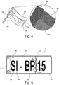
- FIG. 5 A ready-to-use license plate 1 according to the invention is shown in supervision. It is based on the shield blank Fig. 3 , which was provided with a circumferential raised edge 32 and an individual identification legend 34 in a subsequent processing step. Both the edge 32 and the symbols of the license plate legend 34 are raised and produced by means of mechanical stamping of the shield blank 10. After the embossing, the raised embossed areas of the license plate 1, ie the peripheral edge 32 and the identification legend 34, have been permanently colored black by means of a color transfer from a color transfer film in a thermal transfer process.
- Fig. 6 shows a first embodiment of a manufacturing device 100 according to the invention in a schematic representation.
- the device 100 is for Manufacture of a license plate 1 provided and set up. It comprises a blank feed 102 for providing a shield blank 10.
- the blank 10 consists of a (not yet isolated) section of an endless aluminum strip 114 which is unwound from a supply roll 116. These tasks are carried out by the functional unit of the board feeder 110.
- the device 100 comprises a film feed 120 for providing a film 14, for example a retroreflective film with a transparent cover layer as in connection with FIG 1 and 2 explained.
- the film feeder 120 comprises a supply spool 122, on which a supply of the described film 14 is wound up as an endless belt.
- the film structure corresponds to that in connection with Fig. 1 described structure.
- the film 14 to be laminated onto the shield board is unwound and fed to a laminating station 130, in which the film 14 is laminated onto the endless metal strip 114, which is also fed to the laminating station 130.
- a paper liner 128 covering the adhesive layer 16 is pulled off the film 14 and wound onto a take-up roll 126.
- the adhesive layer of the film 14 is further brought into contact with the metal strip 114.
- a (possibly heated) pressure roller 132 arranged in the laminating station 130 applies a defined contact pressure to the film 14 and thus ensures activation of the adhesive layer.
- a punching unit 140 is arranged downstream of the laminating station 130 and cuts individual license plate blanks 10 out of the metallic tape 114, which is laminated with the retroreflective film 14, which are then fed to further processing.
- a mechanical structuring unit 150 in the form of a hot stamping station is arranged between the laminating station 130 assigned to the board supply 110 and the punching unit 140. This is set up to introduce an optically perceptible, extensively extended security structure 30 into the front surface of the shield blank 10, more precisely into the top coat of the retroreflective foil 14 laminated onto the shield plate 12 Security structure 30 a color effect based on optical interference, which is based on regular, raised or recessed structures in the surface of the shield blank 10.
- the structuring unit 150 is in each case set up to produce an optically perceptible security structure 30 which comprises a plurality of discrete surface areas which have at least two different color effects. These different color effects are achieved by, for example, varying the characteristic dimensions of the regular structures, such as the dominant structure spacing.
- the structuring unit 150 comprises a structured metallic stamp (not shown) and is set up to mechanically hot stamp the retroreflective film 14 from the structured stamp into the surface of the top coat of the film 14 and thus of the shield blank 10 by means of mechanical hot stamping transferred to.
- the structuring unit 150 is designed in such a way that the stamping die can be heated, so that it e.g. can be heated to a temperature of over 70 ° C, in particular between 120 ° C and 160 ° C, preferably to 150 ° C.
- the structuring unit 150 is equipped with an additional circuit board heater (not shown) which allows local heating of a shield blank 10 to be embossed in the area in which the security structure 30 is to be mechanically stamped into the surface of the shield blank 10.
- the metallic embossing stamp in turn is provided with a negative of the security structure 30 to be introduced into the surface of the shield blank 10, which is to be molded into the surface of the shield blank 10.
- the structuring of the embossing stamp was generated by means of direct laser interference structuring, ie the structuring of the embossing stamp is based on a structure which was generated by interference from at least two laser beams.
- the two laser beams which can be generated, for example, by beam splitting a laser beam generated by a laser, each have a linear focus. These partial beams are guided that the foci overlap on or in the surface of the previously highly polished stamp, which is made of stainless steel.
- the laser interference structuring of the embossing stamp causes the stamp and the point of incidence of the laser beams on the stamp to be moved relative to one another perpendicularly to the direction of expansion of the foci. It is further provided that an optical mask is imaged on the surface of the stamp in order to form the negative for the optically perceptible, extensively extended security structure on the embossing stamp.
- Fig. 7 shows a second embodiment of a manufacturing device 100 according to the invention again in a schematic representation.
- the manufacturing device 100 according to the second exemplary embodiment corresponds in all its features to the manufacturing device according to the first exemplary embodiment Fig. 6 with the exception of the structuring unit 150, which in this second exemplary embodiment does not work mechanically, but rather is laser-based and therefore contactless.
- the structuring unit 150 comprises a laser (not shown) and is set up to introduce the optically perceptible security structure 30 into the surface of the shield blank 10 by means of interference from at least two laser beams.
- the structuring unit 150 is set up such that the laser beams each have a linear focus and the foci overlap on or in the surface of the shield blank 10 to be structured.
- the laser-based structuring unit 150 is set up to image an optical mask on the surface of the shield blank 10 in order to form the optically perceptible, extensive security structure in the surface of the shield blank 10.
Landscapes
- Engineering & Computer Science (AREA)
- Mechanical Engineering (AREA)
- Vehicle Waterproofing, Decoration, And Sanitation Devices (AREA)
Applications Claiming Priority (3)
| Application Number | Priority Date | Filing Date | Title |
|---|---|---|---|
| DE102016106065.8A DE102016106065A1 (de) | 2016-04-04 | 2016-04-04 | Verfahren zur Herstellung eines retroreflektierenden Kfz-Kennzeichenschilds, retroreflektierendes Kfz-Kennzeichenschild sowie Vorrichtung zur Durchführung des Verfahrens |
| PCT/EP2017/050493 WO2017174221A1 (de) | 2016-04-04 | 2017-01-11 | Verfahren zur herstellung eines retroreflektierenden kfz-kennzeichenschilds, retroreflektierendes kfz-kennzeichenschild sowie vorrichtung zur durchführung des verfahrens |
| EP17700329.0A EP3408143B1 (de) | 2016-04-04 | 2017-01-11 | Verfahren zur herstellung eines retroreflektierenden kfz-kennzeichenschilds, retroreflektierendes kfz-kennzeichenschild sowie vorrichtung zur durchführung des verfahrens |
Related Parent Applications (2)
| Application Number | Title | Priority Date | Filing Date |
|---|---|---|---|
| EP17700329.0A Division-Into EP3408143B1 (de) | 2016-04-04 | 2017-01-11 | Verfahren zur herstellung eines retroreflektierenden kfz-kennzeichenschilds, retroreflektierendes kfz-kennzeichenschild sowie vorrichtung zur durchführung des verfahrens |
| EP17700329.0A Division EP3408143B1 (de) | 2016-04-04 | 2017-01-11 | Verfahren zur herstellung eines retroreflektierenden kfz-kennzeichenschilds, retroreflektierendes kfz-kennzeichenschild sowie vorrichtung zur durchführung des verfahrens |
Publications (1)
| Publication Number | Publication Date |
|---|---|
| EP3659867A1 true EP3659867A1 (de) | 2020-06-03 |
Family
ID=57796351
Family Applications (2)
| Application Number | Title | Priority Date | Filing Date |
|---|---|---|---|
| EP19219268.0A Withdrawn EP3659867A1 (de) | 2016-04-04 | 2017-01-11 | Verfahren zur herstellung eines retroreflektierenden kfz-kennzeichenschilds, retroreflektierendes kfz-kennzeichenschild sowie vorrichtung zur durchführung des verfahrens |
| EP17700329.0A Active EP3408143B1 (de) | 2016-04-04 | 2017-01-11 | Verfahren zur herstellung eines retroreflektierenden kfz-kennzeichenschilds, retroreflektierendes kfz-kennzeichenschild sowie vorrichtung zur durchführung des verfahrens |
Family Applications After (1)
| Application Number | Title | Priority Date | Filing Date |
|---|---|---|---|
| EP17700329.0A Active EP3408143B1 (de) | 2016-04-04 | 2017-01-11 | Verfahren zur herstellung eines retroreflektierenden kfz-kennzeichenschilds, retroreflektierendes kfz-kennzeichenschild sowie vorrichtung zur durchführung des verfahrens |
Country Status (4)
| Country | Link |
|---|---|
| EP (2) | EP3659867A1 (pl) |
| DE (1) | DE102016106065A1 (pl) |
| PL (1) | PL3408143T3 (pl) |
| WO (1) | WO2017174221A1 (pl) |
Families Citing this family (2)
| Publication number | Priority date | Publication date | Assignee | Title |
|---|---|---|---|---|
| DE102017100256A1 (de) | 2017-01-09 | 2018-07-12 | Erich Utsch Ag | Rohling für ein retroreflektierendes Schild sowie Verfahren zu dessen Herstellung, retroreflektierendes Schild Verfahren zu dessen Herstellung |
| EP4594044A1 (de) * | 2022-11-09 | 2025-08-06 | SurFunction GmbH | Verfahren zur herstellung eines werkzeugs, werkzeug, verfahren zur bearbeitung eines werkstücks, werkstück |
Citations (8)
| Publication number | Priority date | Publication date | Assignee | Title |
|---|---|---|---|---|
| US4691993A (en) | 1985-05-13 | 1987-09-08 | Minnesota Mining And Manufacturing Company | Transparent sheets containing directional images and method for forming the same |
| US5009486A (en) * | 1984-06-08 | 1991-04-23 | Canadian Patents And Development Limited/Societe Canadienne Des Brevets Et D'exploitation Limitee | Form depicting, optical interference authenticating device |
| US6594926B1 (en) * | 1999-02-11 | 2003-07-22 | Edward J. Wujciga | Vehicle license plate cover |
| DE10226718A1 (de) * | 2002-05-08 | 2003-11-20 | Utsch Ag Erich | Herstellungsverfahren für Kraftfahrzeug-Kennzeichenschilder, Kraftfahrzeug-Kennzeichenschild und Vorrichtung zur Durchführung des Verfahrens |
| DE102004017094A1 (de) * | 2004-04-07 | 2005-11-03 | Leonhard Kurz Gmbh & Co. Kg | Verfahren zur Herstellung eines Kraftfahrzeug-Nummernschildes sowie ein Kraftfahrzeug-Nummernschild |
| DE102006057507A1 (de) * | 2006-12-06 | 2008-06-12 | Merck Patent Gmbh | Optisch variables Sicherheitselement |
| EP1602946B1 (en) | 2001-07-03 | 2011-10-26 | 3M Innovative Properties Company | Method for attaching a microlens sheeting to a finished article then recording a composite image so that it appears to float upon viewing |
| DE102012011343A1 (de) | 2012-06-11 | 2013-12-12 | Fraunhofer-Gesellschaft zur Förderung der angewandten Forschung e.V. | Vorrichtung und Verfahren zur Interferenzstrukturierung von Proben sowie dergestalt strukturierte Proben |
Family Cites Families (2)
| Publication number | Priority date | Publication date | Assignee | Title |
|---|---|---|---|---|
| DE10020548B4 (de) * | 2000-04-27 | 2011-03-24 | Securasta Gmbh | Plakette, insbesondere Zulassungs-, Prüf-, Siegel- oder Mautplakette, vorzugsweise für Kraftfahrzeuge |
| DE102004017093B4 (de) * | 2004-04-07 | 2007-09-20 | Leonhard Kurz Gmbh & Co. Kg | Prägefolie zur Herstellung fälschungssicherer Kraftfahrzeug-Nummernschilder und fälschungssicheres Kraftfahrzeug-Nummernschild mit einer solchen Prägefolie sowie Verwendung |
-
2016
- 2016-04-04 DE DE102016106065.8A patent/DE102016106065A1/de not_active Ceased
-
2017
- 2017-01-11 EP EP19219268.0A patent/EP3659867A1/de not_active Withdrawn
- 2017-01-11 EP EP17700329.0A patent/EP3408143B1/de active Active
- 2017-01-11 WO PCT/EP2017/050493 patent/WO2017174221A1/de not_active Ceased
- 2017-01-11 PL PL17700329T patent/PL3408143T3/pl unknown
Patent Citations (9)
| Publication number | Priority date | Publication date | Assignee | Title |
|---|---|---|---|---|
| US5009486A (en) * | 1984-06-08 | 1991-04-23 | Canadian Patents And Development Limited/Societe Canadienne Des Brevets Et D'exploitation Limitee | Form depicting, optical interference authenticating device |
| US4691993A (en) | 1985-05-13 | 1987-09-08 | Minnesota Mining And Manufacturing Company | Transparent sheets containing directional images and method for forming the same |
| EP0203752B1 (en) | 1985-05-13 | 1992-08-05 | Minnesota Mining And Manufacturing Company | Transparent sheet containing directional image information and method for its production |
| US6594926B1 (en) * | 1999-02-11 | 2003-07-22 | Edward J. Wujciga | Vehicle license plate cover |
| EP1602946B1 (en) | 2001-07-03 | 2011-10-26 | 3M Innovative Properties Company | Method for attaching a microlens sheeting to a finished article then recording a composite image so that it appears to float upon viewing |
| DE10226718A1 (de) * | 2002-05-08 | 2003-11-20 | Utsch Ag Erich | Herstellungsverfahren für Kraftfahrzeug-Kennzeichenschilder, Kraftfahrzeug-Kennzeichenschild und Vorrichtung zur Durchführung des Verfahrens |
| DE102004017094A1 (de) * | 2004-04-07 | 2005-11-03 | Leonhard Kurz Gmbh & Co. Kg | Verfahren zur Herstellung eines Kraftfahrzeug-Nummernschildes sowie ein Kraftfahrzeug-Nummernschild |
| DE102006057507A1 (de) * | 2006-12-06 | 2008-06-12 | Merck Patent Gmbh | Optisch variables Sicherheitselement |
| DE102012011343A1 (de) | 2012-06-11 | 2013-12-12 | Fraunhofer-Gesellschaft zur Förderung der angewandten Forschung e.V. | Vorrichtung und Verfahren zur Interferenzstrukturierung von Proben sowie dergestalt strukturierte Proben |
Also Published As
| Publication number | Publication date |
|---|---|
| WO2017174221A1 (de) | 2017-10-12 |
| PL3408143T3 (pl) | 2020-10-05 |
| EP3408143B1 (de) | 2020-04-01 |
| DE102016106065A1 (de) | 2017-10-05 |
| EP3408143A1 (de) | 2018-12-05 |
Similar Documents
| Publication | Publication Date | Title |
|---|---|---|
| EP1263610B1 (de) | Laminat, insbesondere in form von karten, und verfahren zu dessen herstellung | |
| EP2585314B1 (de) | Verfahren zur dekoration von oberflächen | |
| EP1440133B1 (de) | Verfahren zum herstellen einer laserbeschriftbaren folie | |
| EP3802144B1 (de) | Verfahren zur herstellung eines laminatkörpers und einer laminierfolie sowie laminatkörper und laminierfolie | |
| WO2017097430A1 (de) | Sicherheitselement mit linsenrasterbild | |
| EP0308904A2 (de) | Mehrschichtige als Druckstock verwendbare Ausweiskarte und Verfahren zu deren Herstellung | |
| EP0866750A1 (de) | Mit einem laserstrahl beschriftbare folie | |
| EP3215371B1 (de) | Datenträger mit durchsichtssicherheitselement | |
| DE102012203350A1 (de) | Sicherheitsetikett und ein Verfahren zu seiner Herstellung | |
| EP3615348A1 (de) | Sicherheitseinlage mit einem uv-auftrag für ein ausweisdokument und verfahren zur herstellung einer sicherheitseinlage mit einem uv-auftrag für ein ausweisdokument | |
| EP1224650B1 (de) | Mit einem laserstrahl beschriftetes etikett, sowie verfahren und vorrichtung zu seiner herstellung | |
| WO2003096257A2 (de) | Kraftfahrzeug-kennzeichenschilder | |
| EP3408143B1 (de) | Verfahren zur herstellung eines retroreflektierenden kfz-kennzeichenschilds, retroreflektierendes kfz-kennzeichenschild sowie vorrichtung zur durchführung des verfahrens | |
| DE102017004037B4 (de) | Sicherheitseinlage mit einer Vertiefung für ein Ausweisdokument und Verfahren zur Herstellung einer Sicherheitseinlage mit einer Vertiefung für ein Ausweisdokument | |
| EP3894232B1 (de) | Verfahren zur herstellung eines folienzwischenprodukts, folienzwischenprodukt sowie verfahren zur herstellung eines produkts | |
| EP2470375B1 (de) | Folienverbund und verfahren zur herstellung des folienverbundes sowie verfahren zur herstellung eines sicherheitsdokumentes mit einem solchen folienverbund | |
| DE10126368A1 (de) | Verfahren und Vorrichtung zur Herstellung eines tragbaren Datenträgers | |
| EP0669214A1 (de) | Verfahren zum Aufbringen und Versiegeln von Informationen auf kartenförmigen Informationsträgern | |
| DE4411404B4 (de) | Schichtverbund zum Übertragen von optisch variablen Einzelelementen auf zu sichernde Gegenstände, Sicherheitsdokument und ein Verfahren zur Herstellung eines Schichtverbunds | |
| DE10226718A1 (de) | Herstellungsverfahren für Kraftfahrzeug-Kennzeichenschilder, Kraftfahrzeug-Kennzeichenschild und Vorrichtung zur Durchführung des Verfahrens | |
| EP3653396A1 (de) | Folienverbund zur beschichtung einer kennzeichenplatine sowie kennzeichenplatine, verfahren und vorrichtung zu deren herstellung | |
| DE102018106398A1 (de) | Schildrohling für ein fälschungssicheres Kennzeichenschild sowie Verfahren zu dessen Herstellung, fälschungssicheres Kennzeichenschild und dessen Herstellung | |
| EP3060408B1 (de) | Verfahren zum bilden mindestens einer dreidimensionalen struktur auf mindestens einer oberfläche eines substrats und transferfolie | |
| DE102018115748A1 (de) | Verfahren und Vorrichtung zur Druckveredelung | |
| EP4282663A1 (de) | Verfahren zur herstellung eines sicherheitsmerkmals, sicherheitsmerkmal für einen datenträger, datenträger und laminierblech |
Legal Events
| Date | Code | Title | Description |
|---|---|---|---|
| PUAI | Public reference made under article 153(3) epc to a published international application that has entered the european phase |
Free format text: ORIGINAL CODE: 0009012 |
|
| STAA | Information on the status of an ep patent application or granted ep patent |
Free format text: STATUS: THE APPLICATION HAS BEEN PUBLISHED |
|
| AC | Divisional application: reference to earlier application |
Ref document number: 3408143 Country of ref document: EP Kind code of ref document: P |
|
| AK | Designated contracting states |
Kind code of ref document: A1 Designated state(s): AL AT BE BG CH CY CZ DE DK EE ES FI FR GB GR HR HU IE IS IT LI LT LU LV MC MK MT NL NO PL PT RO RS SE SI SK SM TR |
|
| STAA | Information on the status of an ep patent application or granted ep patent |
Free format text: STATUS: REQUEST FOR EXAMINATION WAS MADE |
|
| STAA | Information on the status of an ep patent application or granted ep patent |
Free format text: STATUS: EXAMINATION IS IN PROGRESS |
|
| 17P | Request for examination filed |
Effective date: 20201203 |
|
| RBV | Designated contracting states (corrected) |
Designated state(s): AL AT BE BG CH CY CZ DE DK EE ES FI FR GB GR HR HU IE IS IT LI LT LU LV MC MK MT NL NO PL PT RO RS SE SI SK SM TR |
|
| 17Q | First examination report despatched |
Effective date: 20201222 |
|
| STAA | Information on the status of an ep patent application or granted ep patent |
Free format text: STATUS: THE APPLICATION IS DEEMED TO BE WITHDRAWN |
|
| 18D | Application deemed to be withdrawn |
Effective date: 20210930 |