EP3659916B1 - Drehflügler - Google Patents
Drehflügler Download PDFInfo
- Publication number
- EP3659916B1 EP3659916B1 EP17919293.5A EP17919293A EP3659916B1 EP 3659916 B1 EP3659916 B1 EP 3659916B1 EP 17919293 A EP17919293 A EP 17919293A EP 3659916 B1 EP3659916 B1 EP 3659916B1
- Authority
- EP
- European Patent Office
- Prior art keywords
- wing aircraft
- rotary wing
- rotary
- flight
- gravity
- Prior art date
- Legal status (The legal status is an assumption and is not a legal conclusion. Google has not performed a legal analysis and makes no representation as to the accuracy of the status listed.)
- Active
Links
Images



Classifications
-
- B—PERFORMING OPERATIONS; TRANSPORTING
- B64—AIRCRAFT; AVIATION; COSMONAUTICS
- B64C—AEROPLANES; HELICOPTERS
- B64C17/00—Aircraft stabilisation not otherwise provided for
- B64C17/02—Aircraft stabilisation not otherwise provided for by gravity or inertia-actuated apparatus
-
- B—PERFORMING OPERATIONS; TRANSPORTING
- B64—AIRCRAFT; AVIATION; COSMONAUTICS
- B64C—AEROPLANES; HELICOPTERS
- B64C27/00—Rotorcraft; Rotors peculiar thereto
- B64C27/04—Helicopters
- B64C27/08—Helicopters with two or more rotors
-
- B—PERFORMING OPERATIONS; TRANSPORTING
- B64—AIRCRAFT; AVIATION; COSMONAUTICS
- B64U—UNMANNED AERIAL VEHICLES [UAV]; EQUIPMENT THEREFOR
- B64U10/00—Type of UAV
- B64U10/10—Rotorcrafts
- B64U10/13—Flying platforms
- B64U10/14—Flying platforms with four distinct rotor axes, e.g. quadcopters
-
- B—PERFORMING OPERATIONS; TRANSPORTING
- B64—AIRCRAFT; AVIATION; COSMONAUTICS
- B64U—UNMANNED AERIAL VEHICLES [UAV]; EQUIPMENT THEREFOR
- B64U30/00—Means for producing lift; Empennages; Arrangements thereof
- B64U30/20—Rotors; Rotor supports
- B64U30/21—Rotary wings
-
- B—PERFORMING OPERATIONS; TRANSPORTING
- B64—AIRCRAFT; AVIATION; COSMONAUTICS
- B64U—UNMANNED AERIAL VEHICLES [UAV]; EQUIPMENT THEREFOR
- B64U50/00—Propulsion; Power supply
- B64U50/10—Propulsion
- B64U50/19—Propulsion using electrically powered motors
-
- B—PERFORMING OPERATIONS; TRANSPORTING
- B64—AIRCRAFT; AVIATION; COSMONAUTICS
- B64D—EQUIPMENT FOR FITTING IN OR TO AIRCRAFT; FLIGHT SUITS; PARACHUTES; ARRANGEMENT OR MOUNTING OF POWER PLANTS OR PROPULSION TRANSMISSIONS IN AIRCRAFT
- B64D47/00—Equipment not otherwise provided for
- B64D47/08—Arrangements of cameras
-
- B—PERFORMING OPERATIONS; TRANSPORTING
- B64—AIRCRAFT; AVIATION; COSMONAUTICS
- B64U—UNMANNED AERIAL VEHICLES [UAV]; EQUIPMENT THEREFOR
- B64U20/00—Constructional aspects of UAVs
- B64U20/80—Arrangement of on-board electronics, e.g. avionics systems or wiring
- B64U20/87—Mounting of imaging devices, e.g. mounting of gimbals
Definitions
- the present disclosure relates to a rotary wing aircraft. More specifically, the present disclosure relates to a rotary wing aircraft capable of shooting over a long period of time while hovering in a narrow range in the sky in a site such as a tower apartment or a high-rise apartment even when affected by a strong wind during flight. More specifically, the present disclosure relates to a rotary wing aircraft that can maintain the flight unit of the rotary wing aircraft horizontally when the rotary blades of the rotary wing aircraft are stopped during landing or the like.
- Rotary wing aircrafts also called as drones or multi-copters are used in various fields such as security, agriculture, and infrastructure monitoring.
- a rotary wing aircraft By using a rotary wing aircraft, it is possible to observe phenomena occurring in places where humans cannot approach, such as disaster sites and undeveloped land, and it is also possible to analyze the observed big data.
- the rotary wing aircrafts particularly small and lightweight rotary wing aircrafts are being used suitably mainly as rotary wing aircrafts.
- “panoramic aerial photography" is possible in which high-rise building sites such as tower apartments and high-rise apartments can be taken with high resolution.
- rotary wing aircrafts that are small, light and easy to maneuver, less affected by the wind, and capable of maintaining a stable posture are being proposed (for example, Patent Document 1).
- a first support rod is installed so as to be positioned vertically below the rotary wing aircraft from the central portion of the rotary wing aircraft, and a mounting part is installed at the lower part of the first support rod.
- this rotary wing aircraft is provided with a second support rod at the lower part of the mounting part, and a mooring rope is connected to the second support rod.
- the flight range of the rotary wing aircraft is limited by the length of the mooring rope, so it will not be lost even if the rotary wing aircraft falls out of control. Moreover, since this rotary wing aircraft is provided with the mooring rope and a pilot can hold the rotary wing aircraft by winding up the mooring rope, damage from crashing can be prevented.
- the rotary wing aircraft includes a plurality of rotary blades, an arm part that directs the plurality of rotary blades, a first mounting part that mounts an object, and the first mounting part that is movable within a predetermined range.
- a connecting part that connects the first mounting part to the arm part is provided, and the center of lift generated by the rotations of the plurality of rotary blades in the rotary wing aircraft is located at the position of the connecting part.
- the conventional rotary wing aircraft is rolled from side to side by an airflow such as a crosswind generated between tower apartments and between high-rise buildings. Due to this side to side rolling, the rotary wing aircraft tilts while it loses its flight posture. Furthermore, the rotary wing aircraft deviates largely from the site of a tower apartment or a high-rise apartment to fly in the outer region of the site due to the side to side rolling.
- the conventional rotary wing aircraft rolls side to side in response to airflows such as crosswinds generated between tower apartments or high-rise buildings.
- the rotary wing aircraft hovers in a state wherein one side of the rotary blades is tilted. Since the rotary blades are tilted when hovering, the rotary blades are in the way when the rotary wing aircraft is shooting, and there is the problem of the rotary blades of the rotary wing aircraft appearing on the camera screen.
- the present disclosure is directed to restore the flight posture of the rotary wing aircraft to its original flight state by pulling the mooring rope attached to the rotary wing aircraft even when receiving a strong wind such as a crosswind during the flight.
- the present disclosure is directed to provide a rotary wing aircraft that can shoot images over a long period of time while hovering in a narrow range over the site of a tower apartment, a high-rise apartment, or the like even when affected by a strong wind during flight.
- the present disclosure provides a rotary wing aircraft that can enable self-leveling and ensure a stable landing state when the rotary wing aircraft is in a non-energized state immediately before landing.
- the present inventors have found that, by providing a connecting part at the upper end portion of a support member on the rotary wing aircraft, and by locating the connecting part above the center point U of the lift generated in the rotary wing aircraft, the flight posture of the rotary wing aircraft can be re-established and returned to the original flight state, thereby completing the present disclosure.
- a rotary wing aircraft that can ensure a stable landing state by allowing the flight unit to become horizontal and enable self-leveling when the rotary wing aircraft is in a non-energized state immediately before landing.
- a rotary wing aircraft according to an embodiment of the present disclosure has configurations according to the appended claims.
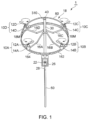
- FIG. 1 is a perspective view illustrating an outline of a rotary wing aircraft 1 of the present disclosure.
- the rotary wing aircraft 1 is provided with a plurality of rotary blade parts 10A to 10D.
- the rotary blade parts 10A to 10D are configured to have rotary blades 12A to 12D and power units 14A to 14D, respectively.
- the rotary blades 12A to 12D rotate in a predetermined direction using the power units 14A to 14D as drive sources, respectively.
- the power units 14A to 14D are not particularly limited as long as they can drive the rotary blades 12A to 12D, respectively, and examples thereof include an electric motor or a small engine.
- the number of the rotary blade parts 10 provided in the rotary wing aircraft of the present disclosure is not particularly limited and can be set appropriately. In the first embodiment, a rotary wing aircraft 1 having four rotary blade parts will be described as an example.
- the rotary wing aircraft 1 is provided with a plurality of arm parts 16A to 16D for supporting a plurality of rotary blade parts 10A to 10D, respectively, an annular flight member 162 that is a base of a flight unit 18, an imaging unit 20 provided below the flight unit 18, and a support member 30 for connecting the flight unit 18 and the imaging unit 20.
- the flight unit 18 and the imaging unit 20 are connected via a lower end portion 34 of the support member 30.
- the imaging unit 20 includes a storage box 22 and a camera body for shooting 26, and the storage box 22 has a box shape for storing the camera body for shooting 26.
- the lower end portion 34 of the support member 30 is connected to a storage box attachment part 24 provided on the upper surface of the imaging unit 20 having a box shape.
- the rotary wing aircraft 1 is configured to have a fixing support member 28, which communicates with the lower surface of the imaging unit 20, for fixing the camera body for shooting 22 in the imaging unit 20 having a box shape.
- the support member 30 and the fixing support member 28 are located on the same straight line.
- a mooring rope 60 for controlling the flight position and flight form of the rotary wing aircraft 1 is attached to the end portion 282 of the fixing support member 28.
- the mooring rope 60 stabilizes the flight state of the rotary wing aircraft 1 in the same manner as the so-called "kite leg”.
- the imaging unit 20 can be kept leveled horizontally.
- the rotary wing aircraft 1 is most suitable for shooting the view of tower apartments, high-rise apartments and such, and is premised on flying in the sky within the site of the tower apartments, high-rise apartments, and such.
- the mooring rope 60 is provided in view of preventing the rotary wing aircraft 1 from flying in the sky outside the site of the tower apartment or the high-rise apartment.
- the mooring rope 60 is attached below the imaging unit 20, how the mooring rope 60 is attached is not particularly limited. For example, it may be attached directly to the bottom surface of the imaging unit 20, without going through the end portion 282 of the fixing support member 28.
- the rotary wing aircraft 1 is provided with arm parts 16A to 16D that support the rotary blade parts 10A to 10D, respectively.
- the arm part 16 which is included in the flight unit 18, is provided with four arms 16A to 16D, but the number of arm parts 16 is not limited thereto.
- the number of arm parts 16 may be set to six or more according to the number of the rotary blade parts 10, for example the number of arm parts 16 can be six or more.
- each arm part 16A to 16D are provided in four directions so as to be equally spaced in an annular shape. That is, the four arm parts 16A to 16D are provided such that the interval between adjacent arm parts is 90°. Further, the arm parts 16A to 16D may have a linear shape or may have a bent shape based on the linear shape in design aspects.
- the arm parts 16A to 16D extend outward at equal intervals around the ring R provided on the outer periphery of the support member 30 as a center.
- the support member 30 communicates with the ring R and extends upward.
- the upper end portion 32 of the support member 30 has a connecting part 40 for connecting the flight unit 18 and the support member 30. Contrary to claim 1, the connecting part 40 has no adjusting mechanism.
- FIG. 2 is a schematic view of the rotary wing aircraft 1 of the first embodiment as viewed from directly above.
- the rotary wing aircraft 1 may have a structure in which bottom end portions of the rotary blade parts 10A to 10D of the plurality of arm parts 16A to 16D are connected, respectively, by a flight member 162.
- the rotary blade parts 10A to 10D located at the ends of the plurality of arm parts 16A to 16D are connected, respectively, by the flight member 162
- the adjacent rotary blade parts 10A to 10D are connected, and the external shape of the flight member 162 viewed from directly above the rotary wing aircraft 1 is an annular shape.
- the shape of the flight member 162 is not particularly limited as long as it can connect the adjacent rotary blade parts 10, and may be an annular, elliptical, or rectangular frame body. By connecting the rotary blade part 10 located at the end of the arm part 16 via the flight member 162, the flight unit 18 is more stable structurally.
- a light emitting body 164 such as a light emitting diode may be provided on the outer side surface of the flight member 162 as a mark when the rotary wing aircraft 1 is flying at night.
- a connecting member 50 for bridging the portion on the opposing flight member 162 with the connecting part 40 is provided through the connecting part 40 installed at the upper end portion 32 of the support member 30, a connecting member 50 for bridging the portion on the opposing flight member 162 with the connecting part 40 is provided.
- the connecting member 50 is driven in synchronization with the connecting part 40 provided on the support member upper end portion 32 of the support member 30.
- the connecting member 50 is inclined or rotated. Since the connecting member 50 is connected to the flight unit 10, the flight unit 10 is inclined or rotated when the connecting part 40 is driven.
- the flight unit 10 inclines or rotates depending on the direction and size in which the connecting part 40 is driven.
- the rotary wing aircraft 1 can incline or rotate the flight unit 10 around the support member 30 as the center.
- the rotary wing aircraft 1 is provided with a connecting member 50 that bridges the intermediate point 181 of the flight unit 18 set between the rotary blade part 10A and the rotary blade part 10D, with the intermediate point 182 of the flight unit 18 set between the rotary blade part B and the rotary blade part C. Since the connecting member 50 passes through the connecting part 40 provided at the upper end portion 32 of the support member 30, the flight unit 18 can be inclined with the connecting part 40 as a vertex when the connecting part 40 is driven. Similarly, the flight unit 18 can also rotate with the connecting part 40 as a vertex, when the connecting part 40 is driven.
- the connecting part 40 is not particularly limited as long as it is a mechanism that can incline or rotate the flight unit 10. It can be set as appropriate according to the function of the rotary wing aircraft.
- a uniaxial gimbal structure, a biaxial gimbal structure, or a triaxial gimbal structure may be adopted as the connecting part 40.
- the gimbal structure may or may not be provided with a driving device such as a motor.
- the flight mode is mainly for vertical ascending, so a biaxial gimbal structure may be used as the connecting part 40.
- the connecting member 50 can be inclined and can also be rotated.
- the connecting member 50 is inclined or rotated, the flight unit 18 connected to the connecting member 50 is inclined or rotated.
- the frame 18 is inclined or rotated, the rotary blades 12A to 12D mounted on the flight unit 18 can be inclined or rotated.
- FIG. 3 is a side view of the rotary wing aircraft 1.
- the flight unit 18 can be inclined or rotated with the connecting part 40 as a vertex, and the connecting part 40 may be located above the center point U of the lift generated in the rotary wing aircraft by rotating a plurality of rotary blades 12A to 12D.
- the support member 30 overlaps the connecting member 50. For this reason, in the rotary wing aircraft 1 shown in FIG. 3 , the connecting member 50 and the support member 30 exist on the same straight line.
- the connecting part 40(1) is located above the center point U(2) of the lift generated in the rotary wing aircraft due to the rotations of the plurality of rotary blades 12A to 12D.
- the connecting part between the flight unit and the support member coincides with the center point U(2) of the lift generated in the rotary wing aircraft as a plurality of rotary blades rotate, or is set at a location lower than the center point U(2) of the lift generated in the rotary wing aircraft.
- the center point G of the connecting part 40 and the center point U of the lift generated in the rotary wing aircraft adopt the above positional relationship, so that the rotary wing aircraft 1 can reestablish its flight posture and can return to its original flight state even if it is affected by strong winds such as crosswinds during flight, by pulling the mooring rope 60 attached to the rotary wing aircraft 1.
- the center of gravity G of the connecting part 40 of the flight unit 18 and the support member 30 is located below the center point U of lift generated in the rotary wing aircraft 1.
- conventional rotary wing aircrafts are subject to an additional downward force even when the mooring rope of the rotorcraft is pulled to restore the original posture from the posture in which the flight posture is lost due to strong winds such as crosswinds.
- the conventional rotary wing aircraft further deteriorates the flight posture of the rotary wing aircraft from the posture in which the flight posture is lost due to strong winds such as crosswinds. Consequently, there are cases where the conventional rotary wing aircraft leaves the sky range in a site such as a high-rise apartment, flies in the sky outside the site, and falls from a high-rise floor.
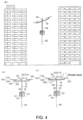
- FIG. 5 is a model diagram showing the flight mode of the rotary wing aircraft 1. Based on FIG. 5 , the flight mode of the rotary wing aircraft 1 of the first embodiment is described. The flight mode of the rotary wing aircraft 1 will be described separately as (a) a process of taking off from the ground on the site of a tower apartment, a high-rise apartment, etc. as the starting point; (b) a process of starting flight by ascending vertically and shooting the high-rise floors of tower apartments, high-rise apartments and such; and (c) a process of landing after shooting the high-rise floors.
- a camera body for shooting 26 is mounted in the storage box 22 configuring the imaging unit 20 of the rotary wing aircraft 1 at a departure place in a site such as a tower apartment or a high-rise apartment.
- An operator of the rotary wing aircraft 1 operates a radio control transmitter having an operation unit to increase the outputs of the power units 14A to 14D of the rotary blade parts 10A to 10D, and increases the numbers of rotations of the rotary blades 12A to 12D, respectively.
- the lift necessary to lift the rotary wing aircraft 1 is generated vertically upward.
- the rotary wing aircraft 1 leaves the ground and takes off from the starting point.
- the rotary blades facing each other in the flight unit 18 rotate in the same direction. Specifically, in the rotary wing aircraft 1, the rotary blade 12A and the rotary blade 12C rotate leftward, and the rotary blade 12B and the rotary blade 12D rotate rightward.
- the rotary wing aircraft 1 ascends vertically toward the sky in the site of a tower apartment, a high-rise apartment, etc. by increasing the numbers of rotations of the rotary blades 12A to 12D. Thereafter, the rotary wing aircraft 1 continues to ascend and reaches a certain altitude.
- the rotary wing aircraft 1 that has reached a certain altitude stays still in the air (hovering) at the altitude.
- the altitude is appropriately determined according to the flight route of the rotary wing aircraft 1, the height of a building such as a tower apartment or a high-rise apartment, the aviation laws applied to the rotary wing aircraft 1, or the like.
- the operator may set the altitude in advance at which the rotary wing aircraft 1 performs staying still in the air (hovering) in consideration of various conditions.
- the rotary wing aircraft Since the weight of the rotary wing aircraft 1 and the lift generated in the rotary wing aircraft 1 by the rotations of the rotary blades 12A to 12D are mechanically balanced, the rotary wing aircraft is able to stay still in the air (hovering). The rotational speeds of the rotary blades 12A to 12D are maintained at constant levels. The staying still in the air (hovering) is performed in order for the rotary wing aircraft 1 to start shooting a tower apartment, a high-rise apartment, etc. using the camera body 26 for shooting.
- the flight unit 18 is inclined.
- the rotational speeds of the rotary blades 12A to 12D included in the flight unit 18 are adjusted to be substantially the same.
- the rotary wing aircraft 1 can start shooting at a position moved horizontally while maintaining the altitude.
- the rotary wing aircraft 1 shoots high-rise floors such as a tower apartment and a high-rise apartment at a predetermined position while staying still in the air (hovering) at a predetermined altitude.
- the rotary wing aircraft 1 can fly in the horizontal direction and change the shooting position as necessary. Further, the rotary wing aircraft 1 can fly in the vertical direction and change the shooting position.
- the rotary wing aircraft 1 lands at a destination in a site such as a tower apartment or a high-rise apartment.
- the destination may be the ground surface, or may be a heliport dedicated to the rotary wing aircraft 1 provided in a tower apartment, a high-rise apartment, or the like.
- the rotary wing aircraft 1 reduces the rotational speeds of the rotary blades 12A to 12D above the destination site.
- the rotary wing aircraft 1 is lowered in altitude and enters a landing posture.
- the flight unit 18 is kept leveled horizontally with respect to the ground surface.
- the rotational speeds of the rotary blades 12A to 12D are adjusted so that the flight unit 18 is horizontal with respect to the ground surface.
- the rotary wing aircraft 1 stops the rotations of the rotary blades 12A to 12D of the flight unit 18 immediately before landing. By stopping the rotations of the rotary blades 12A to 12D, the flight unit 18 becomes horizontal with respect to the ground surface by its own weight. Specifically, in the rotary wing aircraft 1 shown in FIG. 5(c), the rotary blades 12A to 12D are brought into a non-energized state from the state in which the flight unit 18 is inclined as shown by the dotted line. As shown by the solid line, the flight unit 18 becomes horizontal. The rotary blades 12A to 12D are naturally made horizontal due to the influence of gravity.
- the rotary wing aircraft 1 of the present disclosure is provided with the connecting part 40 with the flight unit 18 at the upper end portion 32 of the support member 30, a stable landing state can be ensured when the rotary wing aircraft 1 is in a non-energized state immediately before landing by having the flight unit 18 to be horizontal.
- the rotary wing aircraft 1 can secure a stable flight in the premises of a tower apartment, a high-rise apartment, and the like. Also, it can be suitably used since it is not shaken much during shooting with the camera body for shooting 26. As long as the rotary wing aircraft 1 is staying still in the air (hovering), the rotary wing aircraft 1 of the first embodiment can keep the imaging unit 20 horizontally, and the imaging unit 20 does not shake greatly. For this reason, the rotary wing aircraft 1 can sufficiently cope with the shutter speeds necessary for night scene photography.
- the connecting part 40 has no adjusting mechanism, contrary to claim 1. Since the rotary wing aircraft 2 is designed so that the center point U of the above-mentioned lift and the action point of gravity G coincide, no rotation moment due to gravity by the support member 30 and the imaging unit 20 is generated. For this reason, in the rotary wing aircraft 2 of the second embodiment, when traveling in the horizontal direction, the rotational speeds of the front rotary blades and the rotational speeds of the rear rotary blades can be made substantially equal in the traveling direction.
- the rotary wing aircraft 2 ascends almost vertically from the mooring point of the mooring rope, and is suitable for shooting for a long period of time while hovering in a narrow range. Furthermore, the rotary wing aircraft 2 is further improved in convenience when moving horizontally in a site such as a tower apartment or a high-rise apartment. That is, the rotary wing aircraft 2 is suitable for panoramic photography of a tower apartment, a high-rise apartment, or the like, and has a basic operation of flying vertically (directly above) from the mooring point of a mooring rope.
- the outputs of the power units 14A to 14D for driving the rotary blades 12A to 12D, respectively, can be suppressed.
- the rotary wing aircraft 3 of the third embodiment includes an adjustment mechanism for the support member 30 to extend the length of the support member 30.
- the adjustment mechanism may be provided at the upper part or the lower part with respect to the ring R that engages with the arm parts 16A to 16D provided on the outer periphery of the support member 30.
- the adjustment mechanism extends the length of the support member 30.
- the support member 30 When the rotary wing aircraft 3 lands on a site such as a tower apartment or a high-rise building, the support member 30 is extended vertically downward by the adjusting mechanism. By extending the support member 30 vertically downward, the center of gravity of the rotorcraft 3 moves downward, and a stable landing state can be ensured.
- the rotary wing aircraft of the present disclosure is assumed to be used in a site such as a tower apartment or a high-rise apartment. For this reason, even if the rotary wing aircraft 3 is affected by the rising airflow generated in the vicinity of a tower apartment, a high-rise building, etc., by moving the center of gravity of the rotary wing aircraft 3 downward by the adjustment mechanism at the same time as entering the landing posture, it is possible to maintain a stable flight state against the rising airflow as appropriate.
- the adjustment mechanism is not particularly limited as long as it can extend the length of the support member 30.
- the adjustment mechanism for example, a rack and pinion mechanism or a steering gear mechanism used for focusing in an optical device or the like may be adopted.
- the adjustment mechanism may include a tube structure having elasticity.
- the support member 30 may be configured to have a support member serving as an outer tube and a support member serving as an inner tube.
- the rotary wing aircraft 3 of the third embodiment includes the adjustment mechanism, the distance between the flight unit 18 and the imaging unit 20 can be made as large as possible. For this reason, the rotary wing aircraft 3 according to the third embodiment can secure a deep vertical viewing angle without the flight unit 18 being reflected in the imaging field of view by the camera body for shooting 26 mounted on the imaging unit 20.
- the flight unit 18 and the imaging unit 20 may be farther away from each other compared to conventional rotary wing aircrafts, and so it is possible to shoot the lower floors of tower apartments, high-rise apartments or the like with the imaging unit 20 located at the lower part while at the same time it is possible to shoot a view of the tower apartments and high-rise apartments from the lower floors towards the higher floors.
- the rotary wing aircraft 5 of the fifth embodiment is provided with a plurality of rotary blades 12A to 12D, power units (motors) 14A to 14D for rotating the rotary blades 12A to 12D, respectively, an arm part 16 that supports the power units (motors) 14A to 14, a mounting part 20' that mounts an object such as a camera, and a connecting part 40' that connects the mounting part 20' to the arm part 16 in a movable (displaceable) state wherein the mounting part 20' is within a predetermined range (for example, two axes in the X direction and the Y direction).
- a predetermined range for example, two axes in the X direction and the Y direction.
- the rotary blades 12A to 12D, the power units (motors) 14A to 14D, and the arm part 16 are included in a flight unit 18.
- the mounting part 20' of the present embodiment includes a frame that extends downward from the connecting part 40' and a mounting part that is attached to the front end of the frame.
- the rotary wing aircraft 5 of the present embodiment includes, lined up in a following order from bottom to top, a center of gravity for the entire rotary wing aircraft 5 when stopped G B (airframe center of gravity), a center of gravity of the flight unit 18 G F (flight center of gravity), an action point G L (buoyancy center of gravity) of the lift generated on the airframe due to the rotations of the rotary blades 12A to 12D with respect to the rotary wing aircraft 5, a connecting part 40'. That is, the connecting part 40' of the present embodiment is located above (in the Z direction) the airframe center of gravity G B , the flight center of gravity G F , and the buoyancy center of gravity G .
- the connecting part 40' is configured such that the flight unit 18 can be displaced along the ⁇ x and ⁇ y directions within the two axes of the x direction and the y direction around the connecting part 40'.
- the rotary wing aircraft 5 of the fourth embodiment can ensure stable flight at the site of a tower apartment, a high-rise apartment, etc., similarly to the rotary wing aircrafts of the first to third embodiments. Since there is little shaking of the mounting part 20', it can be suitably used for night scene photography with a camera, for example. In addition, as long as the rotary wing aircraft 5 is staying still in the air (hovering), the rotary wing aircraft 5 of the fourth embodiment can keep the mounting part 20' leveled horizontally, and the mounting part 40' is not greatly shaken. For this reason, it is possible to sufficiently cope with the shutter speeds required for night scene photography.
- the support member 30 of the mounting part 20' is extended vertically downward by the adjustment mechanism 50'.
- the center of gravity of the rotary wing aircraft 3 moves downward, and a more stable landing state can be ensured.
- the rotary wing aircraft of the present disclosure is assumed to be used in a site such as a tower apartment or a high-rise apartment or the like. For this reason, even if the rotary wing aircraft 3 is affected by the rising airflow generated in the vicinity of a tower apartment, a high-rise building, etc., the center of gravity of the rotary wing aircraft 3 is lowered downward by the adjustment mechanism at the same time as entering the landing posture. By moving, it is possible to maintain a stable flight state against the rising airflow as appropriate.
- the adjustment mechanism 50' is not particularly limited as long as the length of the support member 30 can be extended.
- the adjustment mechanism for example, a rack and pinion mechanism or a steering gear mechanism used for focusing in an optical device or the like may be adopted.
- the adjustment mechanism may include a tube structure having elasticity.
- the support member 30 may be configured to have a support member serving as an outer tube and a support member serving as an inner tube.
- the rotary wing aircraft 3 of the third embodiment includes the adjustment mechanism, the distance between the flight unit 18 and the mounting part 20' can be made as large as possible. For this reason, the rotary wing aircraft 3 according to the third embodiment can secure a deep vertical viewing angle without the flight unit 18 being reflected in the imaging field of view by the imaging camera body mounted on the mounting part 20'.
- the flight unit can perform self-leveling at the time of non-energized state (when stopped).
- the rotary wing aircraft of the present disclosure can be suitably used for shooting over a long period of time while hovering in a narrow range above a site such as a tower apartment or a high-rise apartment or the like.
- the rotary wing aircraft of the present disclosure can be expected to be used in surveying sites in low-rise apartment sites and high-rise building construction sites for shooting the view of tower apartments, high-rise buildings, and so on.
- it can be used in various industries such as an industry related to airplanes such as multicopters ⁇ drones and the like, a field related to housing ⁇ construction ⁇ architecture, security field, agriculture, and infrastructure monitoring.
Landscapes
- Engineering & Computer Science (AREA)
- Aviation & Aerospace Engineering (AREA)
- Mechanical Engineering (AREA)
- Chemical & Material Sciences (AREA)
- Combustion & Propulsion (AREA)
- Remote Sensing (AREA)
- Toys (AREA)
Claims (5)
- Ein Drehflügelflugzeug, enthaltend:eine Flugeinheit (18) mit einer Vielzahl von Drehflügeln (12), einer Vielzahl von Antriebseinheiten (14) zum Anbringen und Antreiben der Vielzahl von Drehflügeln (12) und einem Armteil (16) zum Tragen der Vielzahl von Antriebseinheiten (14);ein Befestigungsteil (20') zum Befestigen eines Objekts, wobei das Befestigungsteil (20') einen Einstellmechanismus (50') zum Ausdehnen der Länge des Befestigungsteils (20') enthält; und ein Verbindungsteil (40') zum Verbinden des Befestigungsteils (20') mit dem Armteil (16) in einem Zustand, in dem das Befestigungsteil (20') innerhalb eines vorbestimmten Bereichs beweglich ist,gekennzeichnet durch:das Drehflügelflugzeug von unten nach oben aufgereiht ist:- einen Zelle-Schwerpunkt GB für das Drehflügelflugzeug im Stillstand;- einen Flugschwerpunkt GF der Flugeinheit (18);- einen Auftriebsschwerpunkt GL eines Auftriebs, der an einer Flugzeugzelle aufgrund der Drehungen der Mehrzahl von Drehflügeln (12A) bis (12D) in Bezug auf das Drehflügelflugzeug erzeugt wird, und- das Verbindungsteil (40')wobei die Position des Verbindungsteils (40') oberhalb des Flugwerksschwerpunkts GB, des Flugschwerpunkts GF und des Auftriebsschwerpunkts GL und oberhalb des Befestigungsteils (20') liegt.
- Drehflügelflugzeug nach Anspruch 1, wobei das Verbindungsteil (40') eine zweiachsige kardanische Struktur aufweist.
- Drehflügelflugzeug nach Anspruch 1 oder 2, bei dem ein Seil an dem Befestigungsteil (20') angebracht ist.
- Drehflügelflugzeug nach Anspruch 1, 2 oder 3, wobei die Position des Verbindungsteils (40') oberhalb des Wirkungspunkts des Auftriebs liegt, der durch die Rotationen der mehreren Drehflügel (12) an einer Flugzeugzelle in Bezug auf das Drehflügelflugzeug erzeugt wird.
- Drehflügelflugzeug nach Anspruch 1, 2, 3 oder 4, wobei die Position des Verbindungsteils (40') oberhalb des Schwerpunkts des Drehflügelflugzeugs liegt.
Applications Claiming Priority (1)
| Application Number | Priority Date | Filing Date | Title |
|---|---|---|---|
| PCT/JP2017/027191 WO2019021414A1 (ja) | 2017-07-27 | 2017-07-27 | 回転翼機 |
Publications (3)
| Publication Number | Publication Date |
|---|---|
| EP3659916A1 EP3659916A1 (de) | 2020-06-03 |
| EP3659916A4 EP3659916A4 (de) | 2020-08-12 |
| EP3659916B1 true EP3659916B1 (de) | 2024-01-17 |
Family
ID=65040024
Family Applications (1)
| Application Number | Title | Priority Date | Filing Date |
|---|---|---|---|
| EP17919293.5A Active EP3659916B1 (de) | 2017-07-27 | 2017-07-27 | Drehflügler |
Country Status (5)
| Country | Link |
|---|---|
| US (2) | US11524768B2 (de) |
| EP (1) | EP3659916B1 (de) |
| JP (1) | JP6473244B1 (de) |
| CN (1) | CN110944909B (de) |
| WO (1) | WO2019021414A1 (de) |
Families Citing this family (14)
| Publication number | Priority date | Publication date | Assignee | Title |
|---|---|---|---|---|
| WO2019002995A1 (en) * | 2017-06-27 | 2019-01-03 | Andries Hermann Leuschner | AERIAL VEHICLE WITHOUT PILOT WITH ROTARY WING |
| WO2019021414A1 (ja) * | 2017-07-27 | 2019-01-31 | 株式会社エアロネクスト | 回転翼機 |
| KR102224997B1 (ko) * | 2017-12-11 | 2021-03-09 | 현대모비스 주식회사 | 안전 삼각대 |
| US11453513B2 (en) * | 2018-04-26 | 2022-09-27 | Skydio, Inc. | Autonomous aerial vehicle hardware configuration |
| US11789465B2 (en) * | 2018-06-14 | 2023-10-17 | Georgia Tech Research Corporation | Systems and methods for controlling a vehicle |
| JP6798729B2 (ja) * | 2018-07-19 | 2020-12-09 | 株式会社エアロネクスト | 長尺に延びる本体部を備えた飛行体 |
| KR102270282B1 (ko) * | 2019-05-21 | 2021-06-25 | 김영우 | 안정적인 동작 및 자유도를 가지는 드론 |
| US20230121833A1 (en) * | 2020-03-25 | 2023-04-20 | Nippon Telegraph And Telephone Corporation | Unmanned aerial vehicle |
| JP7471017B2 (ja) * | 2020-05-27 | 2024-04-19 | 株式会社エアロネクスト | 回転翼機 |
| JP6952380B1 (ja) * | 2020-08-11 | 2021-10-20 | 株式会社エアロネクスト | 移動体 |
| CN112339980A (zh) * | 2020-11-27 | 2021-02-09 | 中国科学院沈阳自动化研究所 | 一种火炬传递无人机 |
| MX2024004577A (es) * | 2021-10-15 | 2024-07-10 | Real Time Robotics Inc | Un multicoptero. |
| KR20230107983A (ko) * | 2022-01-10 | 2023-07-18 | 현대자동차주식회사 | 화물 로딩 및 언로딩 장치 |
| US12030399B2 (en) | 2022-04-27 | 2024-07-09 | Skydio, Inc. | Base stations for unmanned aerial vehicles (UAVs) |
Family Cites Families (25)
| Publication number | Priority date | Publication date | Assignee | Title |
|---|---|---|---|---|
| US3096044A (en) * | 1962-02-08 | 1963-07-02 | Gould Morray Whitfield | Helicopter |
| US20120037750A1 (en) * | 2009-04-24 | 2012-02-16 | Valery Vyacheslavovich Dvoeglazov | Airlift |
| FR2959208B1 (fr) | 2010-04-22 | 2012-05-25 | Eurl Jmdtheque | Engin gyropendulaire a propulsion compensatoire et collimation de gradient fluidique multi-milieux multimodal a decollage et atterrissage vertical |
| WO2013052178A2 (en) * | 2011-06-09 | 2013-04-11 | Lasermotive, Inc. | An aerial platform system, and related methods |
| JP2013079034A (ja) * | 2011-10-05 | 2013-05-02 | Zero:Kk | 空撮用回転翼機 |
| US9387939B2 (en) * | 2012-12-20 | 2016-07-12 | Lapcad Engineering, Inc. | VTOL—twin—propeller—attitude—control—air—vehicle |
| CN103921933A (zh) | 2013-01-10 | 2014-07-16 | 深圳市大疆创新科技有限公司 | 飞行器变形结构及微型飞行器 |
| JP6367522B2 (ja) * | 2013-02-28 | 2018-08-01 | 株式会社トプコン | 航空写真システム |
| JP6456641B2 (ja) * | 2014-09-29 | 2019-01-23 | 国立研究開発法人産業技術総合研究所 | マルチロータクラフトの姿勢安定化制御装置 |
| CN104443374A (zh) * | 2014-11-18 | 2015-03-25 | 魏舒璨 | 塔式多旋翼机 |
| JP6179502B2 (ja) * | 2014-12-08 | 2017-08-16 | Jfeスチール株式会社 | マルチコプタを用いた3次元形状計測方法および装置 |
| US10220961B2 (en) * | 2015-03-27 | 2019-03-05 | Aerial Sphere, Llc | Aerial image capturing system |
| EP3299282B1 (de) * | 2015-05-19 | 2021-09-29 | Aeronext Inc. | Drehflügler |
| CN108137151B (zh) * | 2015-09-11 | 2021-09-10 | 深圳市大疆灵眸科技有限公司 | 用于无人飞行器的载体 |
| JP6103013B2 (ja) * | 2015-09-18 | 2017-03-29 | カシオ計算機株式会社 | 情報収集装置、情報収集方法 |
| US10106277B2 (en) * | 2015-10-09 | 2018-10-23 | Carl Michael NEELY | Self-stabilizing spherical unmanned aerial vehicle camera assembly |
| CA3004294A1 (en) * | 2015-11-05 | 2017-05-11 | Walmart Apollo, Llc | Apparatus and method for stabilizing an unmanned aerial system |
| CN105460210B (zh) * | 2015-12-04 | 2018-08-17 | 上海浦江桥隧大桥管理有限公司 | 用于桥梁检测的便携式六旋翼飞行器 |
| US9630713B1 (en) | 2015-12-17 | 2017-04-25 | Qualcomm Incorporated | Unmanned aerial vehicle with adjustable aiming component |
| CN105472252B (zh) * | 2015-12-31 | 2018-12-21 | 天津远度科技有限公司 | 一种无人机获取图像的系统及方法 |
| JP6738611B2 (ja) | 2016-02-02 | 2020-08-12 | 株式会社プロドローン | 無人回転翼機 |
| US10633112B2 (en) * | 2016-04-19 | 2020-04-28 | Fujitsu Limited | Flying machine, method for using flying machine, and flying machine frame |
| CN106005459B (zh) * | 2016-07-14 | 2018-10-19 | 上海风语文化传播有限公司 | 一种无人飞行器 |
| WO2018066043A1 (ja) * | 2016-10-03 | 2018-04-12 | 株式会社Aeronext | 配達用回転翼機 |
| WO2019021414A1 (ja) * | 2017-07-27 | 2019-01-31 | 株式会社エアロネクスト | 回転翼機 |
-
2017
- 2017-07-27 WO PCT/JP2017/027191 patent/WO2019021414A1/ja not_active Ceased
- 2017-07-27 EP EP17919293.5A patent/EP3659916B1/de active Active
- 2017-07-27 US US16/634,074 patent/US11524768B2/en active Active
- 2017-07-27 JP JP2017564749A patent/JP6473244B1/ja active Active
- 2017-07-27 CN CN201780093431.9A patent/CN110944909B/zh active Active
-
2022
- 2022-12-08 US US18/063,480 patent/US11780565B2/en active Active
Also Published As
| Publication number | Publication date |
|---|---|
| CN110944909B (zh) | 2023-06-06 |
| US11780565B2 (en) | 2023-10-10 |
| US11524768B2 (en) | 2022-12-13 |
| US20230126449A1 (en) | 2023-04-27 |
| EP3659916A4 (de) | 2020-08-12 |
| JPWO2019021414A1 (ja) | 2019-07-25 |
| EP3659916A1 (de) | 2020-06-03 |
| WO2019021414A1 (ja) | 2019-01-31 |
| JP6473244B1 (ja) | 2019-02-20 |
| US20200164966A1 (en) | 2020-05-28 |
| CN110944909A (zh) | 2020-03-31 |
Similar Documents
| Publication | Publication Date | Title |
|---|---|---|
| US11780565B2 (en) | Rotary wing aircraft | |
| JP6086519B1 (ja) | 配達用回転翼機 | |
| US8794566B2 (en) | Vehicle capable of stabilizing a payload when in motion | |
| US8794564B2 (en) | Vehicle capable of in-air and on-ground mobility | |
| JP6409503B2 (ja) | 観測装置 | |
| JP3217820U (ja) | ドローン | |
| JP6661199B2 (ja) | 飛行体 | |
| US11628951B2 (en) | Electronic component and aircraft with electronic component attached thereto | |
| JP6661159B2 (ja) | 回転翼機 | |
| JP6694624B2 (ja) | 回転翼機 | |
| JP7083164B2 (ja) | 回転翼機 | |
| JP6661136B1 (ja) | 無人航空機 | |
| JP7019204B2 (ja) | 飛行体 | |
| JP6836815B2 (ja) | 回転翼機 | |
| JP2020029257A (ja) | 回転翼機 | |
| JP7186474B2 (ja) | 飛行体 | |
| KR20180085207A (ko) | 비행체 착륙 장치 및 제어방법 | |
| US20260103302A1 (en) | Offset Drag Reduction Device | |
| JP2007050841A (ja) | 小型回転翼機 |
Legal Events
| Date | Code | Title | Description |
|---|---|---|---|
| STAA | Information on the status of an ep patent application or granted ep patent |
Free format text: STATUS: THE INTERNATIONAL PUBLICATION HAS BEEN MADE |
|
| PUAI | Public reference made under article 153(3) epc to a published international application that has entered the european phase |
Free format text: ORIGINAL CODE: 0009012 |
|
| STAA | Information on the status of an ep patent application or granted ep patent |
Free format text: STATUS: REQUEST FOR EXAMINATION WAS MADE |
|
| 17P | Request for examination filed |
Effective date: 20200224 |
|
| AK | Designated contracting states |
Kind code of ref document: A1 Designated state(s): AL AT BE BG CH CY CZ DE DK EE ES FI FR GB GR HR HU IE IS IT LI LT LU LV MC MK MT NL NO PL PT RO RS SE SI SK SM TR |
|
| AX | Request for extension of the european patent |
Extension state: BA ME |
|
| A4 | Supplementary search report drawn up and despatched |
Effective date: 20200710 |
|
| RIC1 | Information provided on ipc code assigned before grant |
Ipc: B64C 17/02 20060101ALI20200707BHEP Ipc: B64C 27/08 20060101ALI20200707BHEP Ipc: B64D 47/08 20060101ALI20200707BHEP Ipc: B64C 39/02 20060101AFI20200707BHEP |
|
| DAV | Request for validation of the european patent (deleted) | ||
| DAX | Request for extension of the european patent (deleted) | ||
| STAA | Information on the status of an ep patent application or granted ep patent |
Free format text: STATUS: EXAMINATION IS IN PROGRESS |
|
| 17Q | First examination report despatched |
Effective date: 20220408 |
|
| RIC1 | Information provided on ipc code assigned before grant |
Ipc: B64U 101/30 20230101ALI20230801BHEP Ipc: B64U 50/19 20230101ALI20230801BHEP Ipc: B64U 10/13 20230101ALI20230801BHEP Ipc: B64D 47/08 20060101ALI20230801BHEP Ipc: B64C 17/02 20060101ALI20230801BHEP Ipc: B64C 27/08 20060101ALI20230801BHEP Ipc: B64C 39/02 20060101AFI20230801BHEP |
|
| GRAP | Despatch of communication of intention to grant a patent |
Free format text: ORIGINAL CODE: EPIDOSNIGR1 |
|
| STAA | Information on the status of an ep patent application or granted ep patent |
Free format text: STATUS: GRANT OF PATENT IS INTENDED |
|
| INTG | Intention to grant announced |
Effective date: 20230922 |
|
| GRAS | Grant fee paid |
Free format text: ORIGINAL CODE: EPIDOSNIGR3 |
|
| GRAA | (expected) grant |
Free format text: ORIGINAL CODE: 0009210 |
|
| STAA | Information on the status of an ep patent application or granted ep patent |
Free format text: STATUS: THE PATENT HAS BEEN GRANTED |
|
| AK | Designated contracting states |
Kind code of ref document: B1 Designated state(s): AL AT BE BG CH CY CZ DE DK EE ES FI FR GB GR HR HU IE IS IT LI LT LU LV MC MK MT NL NO PL PT RO RS SE SI SK SM TR |
|
| REG | Reference to a national code |
Ref country code: GB Ref legal event code: FG4D |
|
| REG | Reference to a national code |
Ref country code: CH Ref legal event code: EP |
|
| REG | Reference to a national code |
Ref country code: DE Ref legal event code: R096 Ref document number: 602017078605 Country of ref document: DE |
|
| REG | Reference to a national code |
Ref country code: IE Ref legal event code: FG4D |
|
| REG | Reference to a national code |
Ref country code: LT Ref legal event code: MG9D |
|
| REG | Reference to a national code |
Ref country code: NL Ref legal event code: MP Effective date: 20240117 |
|
| REG | Reference to a national code |
Ref country code: AT Ref legal event code: MK05 Ref document number: 1650400 Country of ref document: AT Kind code of ref document: T Effective date: 20240117 |
|
| PG25 | Lapsed in a contracting state [announced via postgrant information from national office to epo] |
Ref country code: NL Free format text: LAPSE BECAUSE OF FAILURE TO SUBMIT A TRANSLATION OF THE DESCRIPTION OR TO PAY THE FEE WITHIN THE PRESCRIBED TIME-LIMIT Effective date: 20240117 |
|
| PG25 | Lapsed in a contracting state [announced via postgrant information from national office to epo] |
Ref country code: NL Free format text: LAPSE BECAUSE OF FAILURE TO SUBMIT A TRANSLATION OF THE DESCRIPTION OR TO PAY THE FEE WITHIN THE PRESCRIBED TIME-LIMIT Effective date: 20240117 |
|
| PG25 | Lapsed in a contracting state [announced via postgrant information from national office to epo] |
Ref country code: IS Free format text: LAPSE BECAUSE OF FAILURE TO SUBMIT A TRANSLATION OF THE DESCRIPTION OR TO PAY THE FEE WITHIN THE PRESCRIBED TIME-LIMIT Effective date: 20240517 |
|
| PG25 | Lapsed in a contracting state [announced via postgrant information from national office to epo] |
Ref country code: LT Free format text: LAPSE BECAUSE OF FAILURE TO SUBMIT A TRANSLATION OF THE DESCRIPTION OR TO PAY THE FEE WITHIN THE PRESCRIBED TIME-LIMIT Effective date: 20240117 |
|
| PG25 | Lapsed in a contracting state [announced via postgrant information from national office to epo] |
Ref country code: GR Free format text: LAPSE BECAUSE OF FAILURE TO SUBMIT A TRANSLATION OF THE DESCRIPTION OR TO PAY THE FEE WITHIN THE PRESCRIBED TIME-LIMIT Effective date: 20240418 |
|
| PG25 | Lapsed in a contracting state [announced via postgrant information from national office to epo] |
Ref country code: RS Free format text: LAPSE BECAUSE OF FAILURE TO SUBMIT A TRANSLATION OF THE DESCRIPTION OR TO PAY THE FEE WITHIN THE PRESCRIBED TIME-LIMIT Effective date: 20240417 Ref country code: HR Free format text: LAPSE BECAUSE OF FAILURE TO SUBMIT A TRANSLATION OF THE DESCRIPTION OR TO PAY THE FEE WITHIN THE PRESCRIBED TIME-LIMIT Effective date: 20240117 |
|
| PG25 | Lapsed in a contracting state [announced via postgrant information from national office to epo] |
Ref country code: ES Free format text: LAPSE BECAUSE OF FAILURE TO SUBMIT A TRANSLATION OF THE DESCRIPTION OR TO PAY THE FEE WITHIN THE PRESCRIBED TIME-LIMIT Effective date: 20240117 |
|
| PG25 | Lapsed in a contracting state [announced via postgrant information from national office to epo] |
Ref country code: AT Free format text: LAPSE BECAUSE OF FAILURE TO SUBMIT A TRANSLATION OF THE DESCRIPTION OR TO PAY THE FEE WITHIN THE PRESCRIBED TIME-LIMIT Effective date: 20240117 |
|
| PG25 | Lapsed in a contracting state [announced via postgrant information from national office to epo] |
Ref country code: RS Free format text: LAPSE BECAUSE OF FAILURE TO SUBMIT A TRANSLATION OF THE DESCRIPTION OR TO PAY THE FEE WITHIN THE PRESCRIBED TIME-LIMIT Effective date: 20240417 Ref country code: NO Free format text: LAPSE BECAUSE OF FAILURE TO SUBMIT A TRANSLATION OF THE DESCRIPTION OR TO PAY THE FEE WITHIN THE PRESCRIBED TIME-LIMIT Effective date: 20240417 Ref country code: LT Free format text: LAPSE BECAUSE OF FAILURE TO SUBMIT A TRANSLATION OF THE DESCRIPTION OR TO PAY THE FEE WITHIN THE PRESCRIBED TIME-LIMIT Effective date: 20240117 Ref country code: IS Free format text: LAPSE BECAUSE OF FAILURE TO SUBMIT A TRANSLATION OF THE DESCRIPTION OR TO PAY THE FEE WITHIN THE PRESCRIBED TIME-LIMIT Effective date: 20240517 Ref country code: HR Free format text: LAPSE BECAUSE OF FAILURE TO SUBMIT A TRANSLATION OF THE DESCRIPTION OR TO PAY THE FEE WITHIN THE PRESCRIBED TIME-LIMIT Effective date: 20240117 Ref country code: GR Free format text: LAPSE BECAUSE OF FAILURE TO SUBMIT A TRANSLATION OF THE DESCRIPTION OR TO PAY THE FEE WITHIN THE PRESCRIBED TIME-LIMIT Effective date: 20240418 Ref country code: FI Free format text: LAPSE BECAUSE OF FAILURE TO SUBMIT A TRANSLATION OF THE DESCRIPTION OR TO PAY THE FEE WITHIN THE PRESCRIBED TIME-LIMIT Effective date: 20240117 Ref country code: ES Free format text: LAPSE BECAUSE OF FAILURE TO SUBMIT A TRANSLATION OF THE DESCRIPTION OR TO PAY THE FEE WITHIN THE PRESCRIBED TIME-LIMIT Effective date: 20240117 Ref country code: BG Free format text: LAPSE BECAUSE OF FAILURE TO SUBMIT A TRANSLATION OF THE DESCRIPTION OR TO PAY THE FEE WITHIN THE PRESCRIBED TIME-LIMIT Effective date: 20240117 Ref country code: AT Free format text: LAPSE BECAUSE OF FAILURE TO SUBMIT A TRANSLATION OF THE DESCRIPTION OR TO PAY THE FEE WITHIN THE PRESCRIBED TIME-LIMIT Effective date: 20240117 |
|
| PG25 | Lapsed in a contracting state [announced via postgrant information from national office to epo] |
Ref country code: PL Free format text: LAPSE BECAUSE OF FAILURE TO SUBMIT A TRANSLATION OF THE DESCRIPTION OR TO PAY THE FEE WITHIN THE PRESCRIBED TIME-LIMIT Effective date: 20240117 Ref country code: PT Free format text: LAPSE BECAUSE OF FAILURE TO SUBMIT A TRANSLATION OF THE DESCRIPTION OR TO PAY THE FEE WITHIN THE PRESCRIBED TIME-LIMIT Effective date: 20240517 |
|
| PG25 | Lapsed in a contracting state [announced via postgrant information from national office to epo] |
Ref country code: SE Free format text: LAPSE BECAUSE OF FAILURE TO SUBMIT A TRANSLATION OF THE DESCRIPTION OR TO PAY THE FEE WITHIN THE PRESCRIBED TIME-LIMIT Effective date: 20240117 Ref country code: PT Free format text: LAPSE BECAUSE OF FAILURE TO SUBMIT A TRANSLATION OF THE DESCRIPTION OR TO PAY THE FEE WITHIN THE PRESCRIBED TIME-LIMIT Effective date: 20240517 Ref country code: PL Free format text: LAPSE BECAUSE OF FAILURE TO SUBMIT A TRANSLATION OF THE DESCRIPTION OR TO PAY THE FEE WITHIN THE PRESCRIBED TIME-LIMIT Effective date: 20240117 Ref country code: LV Free format text: LAPSE BECAUSE OF FAILURE TO SUBMIT A TRANSLATION OF THE DESCRIPTION OR TO PAY THE FEE WITHIN THE PRESCRIBED TIME-LIMIT Effective date: 20240117 |
|
| PGFP | Annual fee paid to national office [announced via postgrant information from national office to epo] |
Ref country code: DE Payment date: 20240729 Year of fee payment: 8 |
|
| PG25 | Lapsed in a contracting state [announced via postgrant information from national office to epo] |
Ref country code: DK Free format text: LAPSE BECAUSE OF FAILURE TO SUBMIT A TRANSLATION OF THE DESCRIPTION OR TO PAY THE FEE WITHIN THE PRESCRIBED TIME-LIMIT Effective date: 20240117 |
|
| PG25 | Lapsed in a contracting state [announced via postgrant information from national office to epo] |
Ref country code: SM Free format text: LAPSE BECAUSE OF FAILURE TO SUBMIT A TRANSLATION OF THE DESCRIPTION OR TO PAY THE FEE WITHIN THE PRESCRIBED TIME-LIMIT Effective date: 20240117 |
|
| REG | Reference to a national code |
Ref country code: DE Ref legal event code: R097 Ref document number: 602017078605 Country of ref document: DE |
|
| PG25 | Lapsed in a contracting state [announced via postgrant information from national office to epo] |
Ref country code: EE Free format text: LAPSE BECAUSE OF FAILURE TO SUBMIT A TRANSLATION OF THE DESCRIPTION OR TO PAY THE FEE WITHIN THE PRESCRIBED TIME-LIMIT Effective date: 20240117 Ref country code: CZ Free format text: LAPSE BECAUSE OF FAILURE TO SUBMIT A TRANSLATION OF THE DESCRIPTION OR TO PAY THE FEE WITHIN THE PRESCRIBED TIME-LIMIT Effective date: 20240117 |
|
| PG25 | Lapsed in a contracting state [announced via postgrant information from national office to epo] |
Ref country code: SK Free format text: LAPSE BECAUSE OF FAILURE TO SUBMIT A TRANSLATION OF THE DESCRIPTION OR TO PAY THE FEE WITHIN THE PRESCRIBED TIME-LIMIT Effective date: 20240117 |
|
| PG25 | Lapsed in a contracting state [announced via postgrant information from national office to epo] |
Ref country code: SM Free format text: LAPSE BECAUSE OF FAILURE TO SUBMIT A TRANSLATION OF THE DESCRIPTION OR TO PAY THE FEE WITHIN THE PRESCRIBED TIME-LIMIT Effective date: 20240117 Ref country code: SK Free format text: LAPSE BECAUSE OF FAILURE TO SUBMIT A TRANSLATION OF THE DESCRIPTION OR TO PAY THE FEE WITHIN THE PRESCRIBED TIME-LIMIT Effective date: 20240117 Ref country code: RO Free format text: LAPSE BECAUSE OF FAILURE TO SUBMIT A TRANSLATION OF THE DESCRIPTION OR TO PAY THE FEE WITHIN THE PRESCRIBED TIME-LIMIT Effective date: 20240117 Ref country code: EE Free format text: LAPSE BECAUSE OF FAILURE TO SUBMIT A TRANSLATION OF THE DESCRIPTION OR TO PAY THE FEE WITHIN THE PRESCRIBED TIME-LIMIT Effective date: 20240117 Ref country code: DK Free format text: LAPSE BECAUSE OF FAILURE TO SUBMIT A TRANSLATION OF THE DESCRIPTION OR TO PAY THE FEE WITHIN THE PRESCRIBED TIME-LIMIT Effective date: 20240117 Ref country code: CZ Free format text: LAPSE BECAUSE OF FAILURE TO SUBMIT A TRANSLATION OF THE DESCRIPTION OR TO PAY THE FEE WITHIN THE PRESCRIBED TIME-LIMIT Effective date: 20240117 |
|
| PLBE | No opposition filed within time limit |
Free format text: ORIGINAL CODE: 0009261 |
|
| STAA | Information on the status of an ep patent application or granted ep patent |
Free format text: STATUS: NO OPPOSITION FILED WITHIN TIME LIMIT |
|
| PG25 | Lapsed in a contracting state [announced via postgrant information from national office to epo] |
Ref country code: IT Free format text: LAPSE BECAUSE OF FAILURE TO SUBMIT A TRANSLATION OF THE DESCRIPTION OR TO PAY THE FEE WITHIN THE PRESCRIBED TIME-LIMIT Effective date: 20240117 |
|
| 26N | No opposition filed |
Effective date: 20241018 |
|
| PG25 | Lapsed in a contracting state [announced via postgrant information from national office to epo] |
Ref country code: IT Free format text: LAPSE BECAUSE OF FAILURE TO SUBMIT A TRANSLATION OF THE DESCRIPTION OR TO PAY THE FEE WITHIN THE PRESCRIBED TIME-LIMIT Effective date: 20240117 |
|
| PG25 | Lapsed in a contracting state [announced via postgrant information from national office to epo] |
Ref country code: MC Free format text: LAPSE BECAUSE OF FAILURE TO SUBMIT A TRANSLATION OF THE DESCRIPTION OR TO PAY THE FEE WITHIN THE PRESCRIBED TIME-LIMIT Effective date: 20240117 |
|
| REG | Reference to a national code |
Ref country code: CH Ref legal event code: PL |
|
| PG25 | Lapsed in a contracting state [announced via postgrant information from national office to epo] |
Ref country code: LU Free format text: LAPSE BECAUSE OF NON-PAYMENT OF DUE FEES Effective date: 20240727 |
|
| GBPC | Gb: european patent ceased through non-payment of renewal fee |
Effective date: 20240727 |
|
| PG25 | Lapsed in a contracting state [announced via postgrant information from national office to epo] |
Ref country code: LU Free format text: LAPSE BECAUSE OF NON-PAYMENT OF DUE FEES Effective date: 20240727 |
|
| PG25 | Lapsed in a contracting state [announced via postgrant information from national office to epo] |
Ref country code: CH Free format text: LAPSE BECAUSE OF NON-PAYMENT OF DUE FEES Effective date: 20240731 Ref country code: SI Free format text: LAPSE BECAUSE OF FAILURE TO SUBMIT A TRANSLATION OF THE DESCRIPTION OR TO PAY THE FEE WITHIN THE PRESCRIBED TIME-LIMIT Effective date: 20240117 Ref country code: BE Free format text: LAPSE BECAUSE OF NON-PAYMENT OF DUE FEES Effective date: 20240731 |
|
| PG25 | Lapsed in a contracting state [announced via postgrant information from national office to epo] |
Ref country code: FR Free format text: LAPSE BECAUSE OF NON-PAYMENT OF DUE FEES Effective date: 20240731 |
|
| PG25 | Lapsed in a contracting state [announced via postgrant information from national office to epo] |
Ref country code: GB Free format text: LAPSE BECAUSE OF NON-PAYMENT OF DUE FEES Effective date: 20240727 |
|
| REG | Reference to a national code |
Ref country code: BE Ref legal event code: MM Effective date: 20240731 |
|
| PG25 | Lapsed in a contracting state [announced via postgrant information from national office to epo] |
Ref country code: IE Free format text: LAPSE BECAUSE OF NON-PAYMENT OF DUE FEES Effective date: 20240727 |
|
| PG25 | Lapsed in a contracting state [announced via postgrant information from national office to epo] |
Ref country code: CY Free format text: LAPSE BECAUSE OF FAILURE TO SUBMIT A TRANSLATION OF THE DESCRIPTION OR TO PAY THE FEE WITHIN THE PRESCRIBED TIME-LIMIT; INVALID AB INITIO Effective date: 20170727 |
|
| REG | Reference to a national code |
Ref country code: DE Ref legal event code: R119 Ref document number: 602017078605 Country of ref document: DE |
|
| PG25 | Lapsed in a contracting state [announced via postgrant information from national office to epo] |
Ref country code: HU Free format text: LAPSE BECAUSE OF FAILURE TO SUBMIT A TRANSLATION OF THE DESCRIPTION OR TO PAY THE FEE WITHIN THE PRESCRIBED TIME-LIMIT; INVALID AB INITIO Effective date: 20170727 |
|
| PG25 | Lapsed in a contracting state [announced via postgrant information from national office to epo] |
Ref country code: DE Free format text: LAPSE BECAUSE OF NON-PAYMENT OF DUE FEES Effective date: 20260203 |