EP3660160A1 - Tragbare vorrichtung und verfahren zum nachweis von mikroorganismen oder metaboliten in einer probe - Google Patents
Tragbare vorrichtung und verfahren zum nachweis von mikroorganismen oder metaboliten in einer probe Download PDFInfo
- Publication number
- EP3660160A1 EP3660160A1 EP18382863.1A EP18382863A EP3660160A1 EP 3660160 A1 EP3660160 A1 EP 3660160A1 EP 18382863 A EP18382863 A EP 18382863A EP 3660160 A1 EP3660160 A1 EP 3660160A1
- Authority
- EP
- European Patent Office
- Prior art keywords
- chamber
- mixture
- detection
- portable device
- tearable seal
- Prior art date
- Legal status (The legal status is an assumption and is not a legal conclusion. Google has not performed a legal analysis and makes no representation as to the accuracy of the status listed.)
- Withdrawn
Links
- 239000002207 metabolite Substances 0.000 title claims abstract description 23
- 244000005700 microbiome Species 0.000 title claims abstract description 23
- 238000000034 method Methods 0.000 title claims abstract description 18
- 239000000203 mixture Substances 0.000 claims abstract description 129
- 238000001514 detection method Methods 0.000 claims abstract description 91
- 239000001963 growth medium Substances 0.000 claims abstract description 21
- 238000004891 communication Methods 0.000 claims abstract description 5
- 238000006073 displacement reaction Methods 0.000 claims description 73
- 230000000415 inactivating effect Effects 0.000 claims description 25
- 239000003795 chemical substances by application Substances 0.000 claims description 19
- 238000000151 deposition Methods 0.000 claims description 7
- 230000005484 gravity Effects 0.000 claims description 5
- 230000008021 deposition Effects 0.000 claims description 4
- 230000000750 progressive effect Effects 0.000 claims description 4
- 230000035515 penetration Effects 0.000 claims description 3
- 238000007789 sealing Methods 0.000 description 20
- 230000008878 coupling Effects 0.000 description 9
- 238000010168 coupling process Methods 0.000 description 9
- 238000005859 coupling reaction Methods 0.000 description 9
- 230000008569 process Effects 0.000 description 6
- 230000007246 mechanism Effects 0.000 description 4
- 239000007787 solid Substances 0.000 description 4
- 238000011065 in-situ storage Methods 0.000 description 2
- 230000002779 inactivation Effects 0.000 description 2
- 241000186781 Listeria Species 0.000 description 1
- 241000607142 Salmonella Species 0.000 description 1
- 230000009471 action Effects 0.000 description 1
- 238000013019 agitation Methods 0.000 description 1
- 230000000903 blocking effect Effects 0.000 description 1
- 230000000295 complement effect Effects 0.000 description 1
- 230000003247 decreasing effect Effects 0.000 description 1
- 239000007788 liquid Substances 0.000 description 1
- 230000002906 microbiologic effect Effects 0.000 description 1
- 238000012986 modification Methods 0.000 description 1
- 230000004048 modification Effects 0.000 description 1
- 230000002093 peripheral effect Effects 0.000 description 1
- 238000003825 pressing Methods 0.000 description 1
- 230000000007 visual effect Effects 0.000 description 1
Images


Classifications
-
- C—CHEMISTRY; METALLURGY
- C12—BIOCHEMISTRY; BEER; SPIRITS; WINE; VINEGAR; MICROBIOLOGY; ENZYMOLOGY; MUTATION OR GENETIC ENGINEERING
- C12Q—MEASURING OR TESTING PROCESSES INVOLVING ENZYMES, NUCLEIC ACIDS OR MICROORGANISMS; COMPOSITIONS OR TEST PAPERS THEREFOR; PROCESSES OF PREPARING SUCH COMPOSITIONS; CONDITION-RESPONSIVE CONTROL IN MICROBIOLOGICAL OR ENZYMOLOGICAL PROCESSES
- C12Q1/00—Measuring or testing processes involving enzymes, nucleic acids or microorganisms; Compositions therefor; Processes of preparing such compositions
- C12Q1/02—Measuring or testing processes involving enzymes, nucleic acids or microorganisms; Compositions therefor; Processes of preparing such compositions involving viable microorganisms
- C12Q1/04—Determining presence or kind of microorganism; Use of selective media for testing antibiotics or bacteriocides; Compositions containing a chemical indicator therefor
-
- G—PHYSICS
- G01—MEASURING; TESTING
- G01N—INVESTIGATING OR ANALYSING MATERIALS BY DETERMINING THEIR CHEMICAL OR PHYSICAL PROPERTIES
- G01N33/00—Investigating or analysing materials by specific methods not covered by groups G01N1/00 - G01N31/00
- G01N33/48—Biological material, e.g. blood, urine; Haemocytometers
- G01N33/50—Chemical analysis of biological material, e.g. blood, urine; Testing involving biospecific ligand binding methods; Immunological testing
- G01N33/53—Immunoassay; Biospecific binding assay; Materials therefor
- G01N33/543—Immunoassay; Biospecific binding assay; Materials therefor with an insoluble carrier for immobilising immunochemicals
- G01N33/54366—Apparatus specially adapted for solid-phase testing
Definitions
- the present invention generally relates, in a first aspect, to a portable device for detecting microorganisms or metabolites in a sample, and more particularly to a portable device which constitutes a kind of microbiologic laboratory for in situ detection without the need of qualified personnel, that allows to perform all the phases needed for the detection within the device in a safe manner.
- a second aspect of the invention relates to a method for detecting microorganisms or metabolites in a sample by using the portable device of the first aspect.
- EP2483388A2 discloses one of those portable devices, and comprises all the features of the preamble of claim 1 of the present invention, i.e.:
- the mixture chamber of the portable device disclosed in said patent application is always fluidically communicated with the enrichment chamber, even when the culture medium is not yet in contact with the sample, not being therefore possible to select at which moment to allow the reception of the enriched mixture therein, such as only once the enriched mixture is provided.
- the detection chamber of the portable device disclosed in EP2483388A2 which is generally part of an external device (such as an injector) can be communicated with the mixture chamber at any moment, with no constraint, no matter if the enrichment mixture has already been received into the mixture chamber.
- the present invention relates, in an aspect, to a portable device for detecting microorganisms or metabolites in a sample, comprising:
- the mixture chamber comprises a sealed, but openable, inlet, to receive the portion of the enriched mixture from the enrichment chamber flowing through the torn first tearable seal and then through said inlet, once opened, and the portable device further comprises:
- the portable device further comprises a filter arranged between the enrichment chamber and the mixture chamber to filter the portion of the enriched mixture to be received by the mixture chamber.
- the above mentioned supporting wall and first tearable seal are the same element, so that when the first tearable seal is torn by the above mentioned means and the portable device is in an upright position, at which the mouth of the enrichment chamber is in an upper position, the sample being supported thereon is automatically displaced by falling by gravity into the enrichment chamber.
- the supporting wall and the first tearable seal are different elements, so that when the first tearable seal is torn the sample supported on the supporting wall is displaced towards the enrichment chamber through the torn first tearable seal, whether only by gravity (for example, if the supporting wall is highly inclined with respect to the first tearable seal) and/or by exerting an external force thereon (by pushing, or just by shaking the portable device).
- the above mentioned opening member and fluidic communication member are the same element, said same element being a moving member configured and arranged to displace according to at least a first displacement path, to adopt a first position at which it opens the sealed inlet of the mixture chamber and, only once said first position has been adopted, move to adopt a distinct and second position at which it fluidically communicates the detection chamber with the mixture chamber.
- the detection chamber is communicated with the mixture chamber through at least one fluidic channel, and comprises a sealed, but openable, aperture configured and arranged to be opened by the moving member when at said second position, so that pressure within the detection chamber equals that of the mixture chamber, the mixture and the detection chambers thus forming communicating vessels so that said aliquot of the portion of the enriched mixture enters into the detection chamber from the mixture chamber and passing through the at least one fluidic channel.
- the inlet of the mixture chamber is sealed by a tearable seal
- said moving member has a tearing portion configured and arranged to tear said tearable seal at least when at said first position.
- the aperture of the detection chamber is also sealed by a tearable seal, and the tearing portion of the moving member is configured and arranged to tear said tearable seal of the aperture of the detection chamber at least when at said distinct and second position.
- a common tearing seal is used for both the inlet of the mixture chamber and the aperture of the detection chamber, the above mentioned tearable seals thereof being different regions of said common tearable seal.
- the tearable seals of the inlet of the mixture chamber and the aperture of the detection chamber are independent tearing seals.
- the moving element is configured and arranged to tear, by means of the tearing portion thereof:
- the moving member is configured and arranged to displace also according to a second displacement path that is transversal to a plane occupied by the tearable seals of the inlet of the mixture chamber and of the aperture of the detection chamber, so that during the displacement of the moving member along the first displacement path the tearing portion moves according to said second displacement path towards the mixture chamber or the detection chamber when facing the corresponding tearable seal.
- the moving member is configured and arranged so that during said displacement according to said second displacement path the tearing portion:
- the mixture and detection chambers project upwards from respective adjacent locations of a base wall, wherein said adjacent locations follow a first circumferential path over the first tearable seal.
- the moving member is located between the first tearable seal and the mixture and detection chambers and is articulated to rotate about a first articulation axis that is orthogonal to a plane occupied by said first tearable seal, to displace according to the first displacement path, which is a rotation displacement path.
- the first displacement path is a linear displacement path.
- the portable device of the first aspect of the present invention comprises, for an embodiment, a manual rotary actuator mechanically connected to the moving member, and that is accessible to a user (for example by means of a rotary knob) to rotate the moving member according to the first, rotating, displacement path.
- a manual rotary actuator mechanically connected to the moving member, and that is accessible to a user (for example by means of a rotary knob) to rotate the moving member according to the first, rotating, displacement path.
- an automatic rotary actuator is arranged instead of said manual rotary actuator.
- the moving member is further articulated about a second articulation axis that is orthogonal to the first axis and pivots there about, to displace according to the second displacement path, which is a pivoting displacement path.
- the tearing portion is located at a first end of the moving member, the moving member having a second end, opposite to said first end, that is guided by means of ramps, defined by adjacent extensions projecting towards the first tearable seal from said base wall and following a second circumferential path, to make the moving member pivot about said second articulation axis when being displaced according to the first, rotating, displacement path, to provide the above mentioned progressive penetration of the tearing portion into the mixture and the detection chambers.
- the portable device of the first aspect of the present invention further comprising at least one of:
- the moving member is configured and arranged to move to tear, with its tearing portion, respective seals of the aperture or inlets of the different chambers according to the following order: first the reactive chamber, then the mixture chamber, then the detection chamber, and finally the inactivating chamber,
- the present invention also relates, in a second aspect, to a method for detecting microorganisms or metabolites in a sample, using a portable device according to any of the previous claims, the method comprising sequentially performing the following steps:
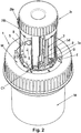
- the appended Figures show a preferred embodiment of the portable device of the first aspect of the present invention.
- the device comprises a lower part and an upper part coupleable to each other.
- the lower part comprises, as shown in Figures 1 , and 3 to 7 :
- Figure 5 shows the upper and lower parts uncoupled, with a sample S (in this case a solid sample) having been introduced within the collecting chamber 16 deposited on the first tearable seal 13.
- a sample S in this case a solid sample
- the upper part of the device comprises, as shown especially in Figures 1 , and 3 to 7 , means for tearing the first tearable seal 13, so that both the collecting chamber 16 and the enrichment chamber 14 are communicated such that the sample S falls into the interior of the enrichment chamber 14 (as shown in Figure 7 ) through the torn first tearable seal 13, so that the sample S is enriched with the culture medium M for a microorganism or metabolite of interest, and an enriched mixture of the culture medium M and the sample S is provided.
- those means for tearing comprise cutting elements C arranged on the peripheral free edge of a hollow tubular portion T projecting downwards (according to the spatial position shown in Figure 1 ) from a circular base wall W.
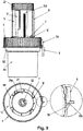
- Figure 6 shows how the upper part is coupled to the lower part by screwing, particularly by means of the two mutually threaded complementary surfaces 1a, 16a (see Figures 1 and 5 ) respectively defined in an inner surface of a ring part 1 and an outer surface of the collecting chamber 16.
- the stop elastic member E In order to unlock said screwing displacement, to cause the tearing of the tearable seal 13, the stop elastic member E must be pressed by a user as indicated by the horizontal arrow depicted in Figure 6 , until achieving the position at which the stop elastic member is illustrated in a dashed line in Figure 6 .
- the screwing displacement can go on so that the ring part 1 (and thus the components attached thereto) goes downwards, the cutting elements C reach and tear the tearable seal 13 such that the sample S falls by gravity into the enrichment chamber 14, and a maximum coupling course position is reached, providing a stable coupling and also in a sealed manner thanks to the sealing ring 6 being trapped against the inner wall of the collecting chamber 16.
- the portable device of the first aspect of the present invention further comprises a mixture chamber 5m that comprises a sealed, but openable, inlet 5ma, to be fluidically communicable with the enrichment chamber 14 for receiving a portion of the enriched mixture from the enrichment chamber 14, once a seal 10 sealing that inlet 5ma is torn.
- a mixture chamber 5m that comprises a sealed, but openable, inlet 5ma, to be fluidically communicable with the enrichment chamber 14 for receiving a portion of the enriched mixture from the enrichment chamber 14, once a seal 10 sealing that inlet 5ma is torn.
- a removable tubular member 8 is placed within the mixture chamber 5m (not shown in Figure 4 , for clarity sake), that tubular member 8 being fluidically communicated with the inlet 5ma, so that the portion of the enriched mixture is received into the mixture chamber by flowing through the tubular member 8 and outing through the upper end of the tubular member 8.
- the portable device must be upside down with respect to the upright position illustrated in the Figures, or at least facing down, if not vertically in an inclined manner with an inclination that is enough to make the portion of the enrichment mixture flow into the mixture chamber 5m through the tubular member 8.
- tubular member 8 could be non-removable but fixedly housed within the mixture chamber 5m.
- the portable device must be put back into the upright position, so that the portion of the enrichment mixture occupies an inner volume of the mixture chamber 5m adjacent to the tubular member 8, and remains therein until is communicated with an adjacent detection chamber 5d that will be described below.
- the portable device also comprises the above mentioned detection chamber 5d, which is fluidically communicable with the mixture chamber 5m to receive an aliquot of the portion of the enriched mixture therefrom, so that the presence of the microorganism or metabolite of interest can be detected in the aliquot by means of a detection element 9 (in this case a chromatographic strip) housed there within.
- a detection element 9 in this case a chromatographic strip
- the detection chamber 5d is communicated with the mixture chamber 5m through a fluidic channel Ch, and comprises a sealed, but openable, aperture 5da (see also Figure 3 ) configured and arranged to be opened so that pressure within the detection chamber 5d equals that of the mixture chamber 5m, the mixture 5m and the detection 5d chambers thus forming communicating vessels so that the aliquot of the portion of the enriched mixture enters into the detection chamber 5d from the mixture chamber 5m, particularly from the above mentioned volume adjacent to the tubular member 8, and passing through the fluidic channel Ch, as signed by the arrow lines depicted in Figure 2 .
- a sealed, but openable, aperture 5da (see also Figure 3 ) configured and arranged to be opened so that pressure within the detection chamber 5d equals that of the mixture chamber 5m, the mixture 5m and the detection 5d chambers thus forming communicating vessels so that the aliquot of the portion of the enriched mixture enters into the detection chamber 5d from the mixture chamber 5m, particularly from the above mentioned volume adjacent to the tubular
- At least a portion of the detection chamber 5d is translucent at a region through which the detection element can be seen from outside the device, so that, in case of a chromatographic strip, the results of the detection can be seen by looking thereto through said translucent region.
- a common tearable seal 10 is used for sealing both the inlet 5ma of the mixture chamber 5m and the aperture 5da of the detection chamber 5d, so that different regions thereof seal the corresponding inlet 5ma and aperture 5da.
- the detection element 9 is supported on a support member 7 removably placed within the detection chamber 5d (for a non-illustrated embodiment, that support member 7 could instead be fixedly attached within the detection chamber 5d). That support member 7, as shown in Figure 2 , is opened at a bottom portion adjacent to the detection element 9, by means of a through opening 7a fluidically communicated with aperture 5da, for the purpose of draining back to the enrichment chamber 14 an excess of the portion of the enrichment mixture received there into (as signed by the arrow lines depicted in Figure 2 ), such that only a predetermined aliquot thereof remains within the detection chamber 5d, in this case in contact with the lower part of the detection element 9.
- a moving member 11 is provided that is configured and arranged to displace according to at least a first displacement path, to adopt a first position at which a tearing portion 11a thereof tears the region of the common tearable seal 10 sealing inlet 5ma of the mixture chamber 5m (as showing in Figure 4 ) and, only once that first position has been adopted, move to adopt a distinct and second position at which the tearing portion 11a tears the region of the common tearable seal 10 sealing aperture 5da of the detection chamber 5d, so that the aliquot of the portion of the enriched mixture enters into the detection chamber 5d as explained above, coming from the mixture chamber 5m through channel Ch.
- the moving member 11 is located between the first tearable seal 13 and the mixture 5m and detection 5d chambers and is articulated to rotate about a first articulation axis A1 (in this case, a vertical axis) that is orthogonal to a plane occupied by the first tearable seal 13, to displace according to the first displacement path, which is a rotation displacement path.
- a first articulation axis A1 in this case, a vertical axis
- a manual rotary actuator 2 mechanically connected to the moving member 11 is provided for the illustrated embodiment, and that is accessible to a user, in this case through a rotary knob 2r, to rotate the moving member 11 according to the first, rotating, displacement path.
- that rotation displacement is carried out counterclockwise, so that the region of the common seal 10 sealing inlet 5ma is torn before the one sealing aperture 5da: however, if, for a non-illustrated embodiment, the position of the mixture 5m and detection 5d chambers was interchanged, then the device would be modified so that that rotation displacement would be clockwise.
- the moving member 11 is configured and arranged to displace also according to a second displacement path that is transversal to a plane occupied by the tearable seal 10, so that during the displacement of the moving member 11 along the first, rotation, displacement path the tearing portion 11a moves according to the second displacement path towards the mixture chamber 5m or the detection chamber 5d when facing the corresponding region of the tearable seal 10.
- That displacement along the second displacement path is provided by means of the moving member 11 being further articulated about a second articulation axis A2 (see Figure 1 ) that is orthogonal to the first axis A1 and pivots there about, to displace according to the second displacement path, which is a pivoting displacement path.
- the tearing portion 11a is located at a first end of the moving member 11, the moving member 11 having a second end 11b, opposite to the first end 11a, the moving member being articulated about the second articulation axis A2 at an intermediate point such that the tearing portion 11a and the second end 11b go in opposite directions when the second displacement occurs.
- the moving member 11 is specifically articulated to a further moving member 12, by means of articulation configurations Hb, Ha, to cause the pivoting displacement about the second axis A2.
- the second end 11b is guided by means of ramps defined by adjacent extensions R projecting towards the first tearable seal 13 from the base wall W and following a second circumferential path having a larger diameter than the first circumferential path, to make the moving member 11 pivot about the second articulation axis A2 when being displaced according to the first, rotating, displacement path.
- the extensions R have a triangular-like shape formed by two respective ramps converging at a lower convergence point, and are arranged so that when and during the displacement of the moving member 11 rotating about the first axis A1, the second end 11b contacts and runs first through a first ramp of a respective extension R such that that second end 11b is pushed downwards (according to the illustrated position) until it reaches the convergence point, and hence, by pivoting the moving member 11 about the second articulation axis A2, as shown in Figure 4 , the first end including the tearing portion 11a is pushed upwards so that it progressively tears the corresponding region of the tearable seal 10 covering inlet 5ma and penetrates into the mixture chamber 5m there through, increasingly until the above mentioned first position is achieved along the rotation displacement about the first articulation axis A1.
- the tearing portion 11a continues the progressive tearing of the rest of the corresponding region of the tearable seal 10 according to a decreasing penetration caused by the tearing portion 11a being pushed away from the mixture chamber 5m, so that, by pivoting the moving member 11 about the second articulation axis A2, the second end 11b is pushed towards the base wall W running through the other ramp of the extension R.
- the mixture 5m and detection 5d chambers project upwards, when the portable device is in an upright position, from respective adjacent locations of a base wall W, wherein said adjacent locations follow a first circumferential path over said first tearable seal 13,
- the manual rotary actuator 2r is removably clipped to an end portion 12a of the further moving member 12, particularly by means of elastic tabs 2c, as shown in Figure 3 .
- the further moving member 12 is also removably clipped to the base wall W, by its introduction in a central through hole thereof and the trapping of portions of the base wall surrounding the contour of said central through hole between elastic tabs 12b and top edge of a tubular portion 12c, as shown in Figure 3 .
- the base wall W (and the rest of components attached thereto) is also removably attached to the ring part 1 by means of elastic tabs f (see Figures 1 and 9 ) that trap an upper wall of the ring part 1 between them and an upper face of the wall W from which the elastic tabs f project upwards (according to the position illustrated in Figure 1 ).
- tabs g are also provided projecting upwards from the upper face of the wall W, with the purpose of limiting a radial relative displacement between the base wall W (and the rest of components attached thereto) and the ring part 1.
- the portable device of the first aspect of the present invention also comprises a filter F arranged between the enrichment chamber 14 and the mixture chamber 5m to filter the portion of the enriched mixture to be received by the mixture chamber 5m.
- the filter F is a downwards and radial extension of the tubular portion 12c of the further moving member 12c.
- the portable device of the first aspect of the present invention further comprises:
- only one of the reactive 5r and inactivating 5i chambers is comprised by the device.
- the apertures 5ra and 5ia are both sealed by other corresponding regions of the common seal 10.
- the reactive 5r and inactivating 5i also project upwards, when the portable device is in an upright position, from respective adjacent locations of the base wall W, following the first circumferential path over the first tearable seal 13, adjacent to each other.
- the reactive chamber 5r is placed adjacent to the mixture chamber 5m, and the inactivating chamber 5i is placed adjacent to the detection chamber 5d, so that during the rotation displacement of the moving member 11 about the first articulation axis A1, the region of the common seal 10 covering the aperture 5ra is first torn (by means of the same process explained above for the inlet 5ma and the aperture 5da), in order to pour a reactive agent to the enrichment chamber 14, then the one covering inlet 5ma, then the one covering aperture 5da, and finally the one covering aperture 5ia in order to pour an inactivating agent to the enrichment chamber to inactivate the contents thereof.
- septums are provided for introducing or extracting the contents of some of the chambers, particularly, as shown in Figure 1 , septums 3 for the detection 5d and inactivating 5i chambers, and septum 15 for the enrichment chamber 15.
- that mechanism comprises two tabs 2ta, 2tb (see figures 2 and 4 ) that project downwards from a free lower end of rotary knob 2r, and a fin B projecting radially from the outer contour of one of the chambers (in this case of inactivating chamber 5i) that before use of the device remains trapped between both tabs 2ta, 2tb, thus blocking the rotation of the rotary knob 2r and of all the components attached thereto, in both directions.
- Tab 2ta is breakable, or at least foldable, by a user in order to allow the counterclockwise rotation of the rotary knob 2r and of all the components attached thereto without colliding with fin B.
- the tabs 2ta, 2tb, fin B, manual rotary actuator 2, moving member 11, further moving member 12, and chambers 5r, 5m, 5d, 5i, are configured and arranged so that when the tab 2ta is broken or fold, the counterclockwise rotation can be initiated and the first region of the common seal 10 found and thus torn by the tearing portion 11a is that sealing aperture 5ra, then that sealing inlet 5ma, then that sealing aperture 5da and finally that sealing aperture 5ia.
- Tab 2tb is not breakable in order to prevent a clockwise rotation of the rotary knob 2r without colliding with fin B, that would cause to invert the tearing order described above.
- the region of the common tearable seal 10 sealing aperture 5da cannot be torn if the one sealing inlet 5ma has not yet been torn, the one covering aperture 5ma cannot be torn if the one sealing aperture 5ra has not yet been torn, and the one sealing aperture 5ia cannot be torn if the one sealing aperture 5da has not yet been torn.
- each chamber is identified by means of a corresponding indicator.
- those indicators are respective vertical ridges Rd: one for the reactive chamber 5r, two for the mixture chamber 5m, three for the detection chamber 5d, and four for the inactivating chamber 5i.
- the present invention also relates, in a second aspect, to a method for detecting microorganisms or metabolites in a sample S, using a portable device according to any of the previous claims.
- the method comprising sequentially performing an enrichment process comprising sequentially performing the following steps:
- the method further comprises a detection process comprising sequentially performing the following steps:
- the method further comprises tearing the region of the seal 10 covering aperture 5ra before that of inlet 5ma, as explained above, so as to pour, while the device is in the upright position, a reactive agent contained therein into the enrichment chamber 14.
- the method of the invention comprises an inactivation process that comprises sequentially performing the following steps:
Landscapes
- Health & Medical Sciences (AREA)
- Life Sciences & Earth Sciences (AREA)
- Immunology (AREA)
- Engineering & Computer Science (AREA)
- Chemical & Material Sciences (AREA)
- Molecular Biology (AREA)
- Hematology (AREA)
- Urology & Nephrology (AREA)
- Biomedical Technology (AREA)
- Analytical Chemistry (AREA)
- Physics & Mathematics (AREA)
- Biochemistry (AREA)
- Biotechnology (AREA)
- Microbiology (AREA)
- Organic Chemistry (AREA)
- General Health & Medical Sciences (AREA)
- Proteomics, Peptides & Aminoacids (AREA)
- Food Science & Technology (AREA)
- Pathology (AREA)
- Zoology (AREA)
- General Physics & Mathematics (AREA)
- Wood Science & Technology (AREA)
- Cell Biology (AREA)
- Medicinal Chemistry (AREA)
- Genetics & Genomics (AREA)
- Toxicology (AREA)
- Biophysics (AREA)
- Bioinformatics & Cheminformatics (AREA)
- General Engineering & Computer Science (AREA)
- Investigating Or Analysing Biological Materials (AREA)
Priority Applications (2)
| Application Number | Priority Date | Filing Date | Title |
|---|---|---|---|
| EP18382863.1A EP3660160A1 (de) | 2018-11-28 | 2018-11-28 | Tragbare vorrichtung und verfahren zum nachweis von mikroorganismen oder metaboliten in einer probe |
| PCT/EP2019/082889 WO2020109457A1 (en) | 2018-11-28 | 2019-11-28 | Portable device and method for detecting microorganisms or metabolites in a sample |
Applications Claiming Priority (1)
| Application Number | Priority Date | Filing Date | Title |
|---|---|---|---|
| EP18382863.1A EP3660160A1 (de) | 2018-11-28 | 2018-11-28 | Tragbare vorrichtung und verfahren zum nachweis von mikroorganismen oder metaboliten in einer probe |
Publications (1)
| Publication Number | Publication Date |
|---|---|
| EP3660160A1 true EP3660160A1 (de) | 2020-06-03 |
Family
ID=64665083
Family Applications (1)
| Application Number | Title | Priority Date | Filing Date |
|---|---|---|---|
| EP18382863.1A Withdrawn EP3660160A1 (de) | 2018-11-28 | 2018-11-28 | Tragbare vorrichtung und verfahren zum nachweis von mikroorganismen oder metaboliten in einer probe |
Country Status (2)
| Country | Link |
|---|---|
| EP (1) | EP3660160A1 (de) |
| WO (1) | WO2020109457A1 (de) |
Citations (11)
| Publication number | Priority date | Publication date | Assignee | Title |
|---|---|---|---|---|
| EP0264221A2 (de) * | 1986-10-06 | 1988-04-20 | BioControl Systems, Inc. | Verfahren und Vorrichtung zum Nachweis von Mikroorganismen |
| EP1712614A1 (de) * | 2004-02-04 | 2006-10-18 | Srl, Inc. | Einfacher tragbarer bakterien-detektor |
| WO2009024930A2 (en) * | 2007-08-22 | 2009-02-26 | Agricultural Research Council | Activation and delivery container and method |
| WO2010078482A1 (en) * | 2008-12-31 | 2010-07-08 | 3M Innovative Properties Company | Live bioload detection using microparticles |
| WO2011037348A2 (ko) * | 2009-09-22 | 2011-03-31 | 일렉트론 바이오 주식회사 | 미생물 분석 장치 및 이를 이용한 분석 방법 |
| WO2011039198A2 (en) * | 2009-09-29 | 2011-04-07 | Fundación Gaiker | Portable enrichment, aliquoting, and testing device of microorganisms and toxins |
| WO2013181616A1 (en) * | 2012-06-02 | 2013-12-05 | Health & Bliss Llc | Self diagnostic test |
| WO2016172800A1 (en) * | 2015-04-28 | 2016-11-03 | Aterica Inc. | Portable organic molecular sensing device and related systems and methods |
| DE102015112343A1 (de) * | 2015-07-29 | 2017-02-02 | Westfälische Wilhelms-Universität Münster | Vorrichtung und Verfahren zum Aufbereiten von Körperflüssigkeiten |
| WO2017027384A1 (en) * | 2015-08-07 | 2017-02-16 | Poc Medical Systems, Inc. | Microfluidic devices and methods of use thereof |
| WO2017077467A1 (en) * | 2015-11-06 | 2017-05-11 | Traces S.R.L. | Container for collection and preservation of biopsy samples |
-
2018
- 2018-11-28 EP EP18382863.1A patent/EP3660160A1/de not_active Withdrawn
-
2019
- 2019-11-28 WO PCT/EP2019/082889 patent/WO2020109457A1/en not_active Ceased
Patent Citations (12)
| Publication number | Priority date | Publication date | Assignee | Title |
|---|---|---|---|---|
| EP0264221A2 (de) * | 1986-10-06 | 1988-04-20 | BioControl Systems, Inc. | Verfahren und Vorrichtung zum Nachweis von Mikroorganismen |
| EP1712614A1 (de) * | 2004-02-04 | 2006-10-18 | Srl, Inc. | Einfacher tragbarer bakterien-detektor |
| WO2009024930A2 (en) * | 2007-08-22 | 2009-02-26 | Agricultural Research Council | Activation and delivery container and method |
| WO2010078482A1 (en) * | 2008-12-31 | 2010-07-08 | 3M Innovative Properties Company | Live bioload detection using microparticles |
| WO2011037348A2 (ko) * | 2009-09-22 | 2011-03-31 | 일렉트론 바이오 주식회사 | 미생물 분석 장치 및 이를 이용한 분석 방법 |
| WO2011039198A2 (en) * | 2009-09-29 | 2011-04-07 | Fundación Gaiker | Portable enrichment, aliquoting, and testing device of microorganisms and toxins |
| EP2483388A2 (de) | 2009-09-29 | 2012-08-08 | Fundacion Gaiker | Tragbare anreicherungs-, aliquotierungs- und prüfvorrichtung für mikroorganismen und toxine |
| WO2013181616A1 (en) * | 2012-06-02 | 2013-12-05 | Health & Bliss Llc | Self diagnostic test |
| WO2016172800A1 (en) * | 2015-04-28 | 2016-11-03 | Aterica Inc. | Portable organic molecular sensing device and related systems and methods |
| DE102015112343A1 (de) * | 2015-07-29 | 2017-02-02 | Westfälische Wilhelms-Universität Münster | Vorrichtung und Verfahren zum Aufbereiten von Körperflüssigkeiten |
| WO2017027384A1 (en) * | 2015-08-07 | 2017-02-16 | Poc Medical Systems, Inc. | Microfluidic devices and methods of use thereof |
| WO2017077467A1 (en) * | 2015-11-06 | 2017-05-11 | Traces S.R.L. | Container for collection and preservation of biopsy samples |
Also Published As
| Publication number | Publication date |
|---|---|
| WO2020109457A1 (en) | 2020-06-04 |
Similar Documents
| Publication | Publication Date | Title |
|---|---|---|
| US5325765A (en) | Beverage filter cartridge | |
| RU2461508C2 (ru) | Емкость для дисперсных материалов | |
| US10843866B2 (en) | Method and apparatus for cartridge-based carbonation of beverages | |
| US20150016208A1 (en) | Multi-chamber container for storing and mixing liquids | |
| JP6246735B2 (ja) | カートリッジ保持器を用いた飲料生成装置および飲料生成方法 | |
| EP3157834B1 (de) | Verschluss mit speicherkammer | |
| CZ25798A3 (cs) | Přístroj pro smíchání dvou odlišných kapalin | |
| JP2014524287A (ja) | 透析用容器 | |
| MX2008014255A (es) | Valvula de dos vias. | |
| US5425920A (en) | Vial for chemical reagents | |
| AU2020345078B2 (en) | Releasing stopper, container provided with stopper and kits and releasing method associated thereto | |
| EP3974343A1 (de) | Zwei-flüssigkeits-behälter | |
| JP5719542B2 (ja) | 注出キャップ | |
| CN108861045B (zh) | 一种用于定量取液的定量出液盖 | |
| KR20140109015A (ko) | 잔량 개선을 위한 이종 내용물 혼합용기 | |
| EP3660160A1 (de) | Tragbare vorrichtung und verfahren zum nachweis von mikroorganismen oder metaboliten in einer probe | |
| US4326959A (en) | Blood separator and dispenser | |
| EP3265813B1 (de) | Zweiwege-immunoassayvorrichtung mit integriertem puffer | |
| KR102072808B1 (ko) | 더치커피 추출 장치 | |
| JP3929812B2 (ja) | 流体用容器 | |
| AU2019341671B2 (en) | A sampling device, a system comprising the sampling device and a method | |
| CN211148659U (zh) | 一种检测装置 | |
| CA3100506C (en) | A sampling device, a system comprising the sampling device and a method | |
| JP7477445B2 (ja) | 回転式計量ポンプ | |
| CN220257426U (zh) | 一种方便回收浓缩液的离心过滤装置 |
Legal Events
| Date | Code | Title | Description |
|---|---|---|---|
| PUAI | Public reference made under article 153(3) epc to a published international application that has entered the european phase |
Free format text: ORIGINAL CODE: 0009012 |
|
| STAA | Information on the status of an ep patent application or granted ep patent |
Free format text: STATUS: THE APPLICATION HAS BEEN PUBLISHED |
|
| AK | Designated contracting states |
Kind code of ref document: A1 Designated state(s): AL AT BE BG CH CY CZ DE DK EE ES FI FR GB GR HR HU IE IS IT LI LT LU LV MC MK MT NL NO PL PT RO RS SE SI SK SM TR |
|
| AX | Request for extension of the european patent |
Extension state: BA ME |
|
| STAA | Information on the status of an ep patent application or granted ep patent |
Free format text: STATUS: THE APPLICATION IS DEEMED TO BE WITHDRAWN |
|
| 18D | Application deemed to be withdrawn |
Effective date: 20201204 |