EP3660251A1 - Dispositif de protection, en particulier portail industriel - Google Patents
Dispositif de protection, en particulier portail industriel Download PDFInfo
- Publication number
- EP3660251A1 EP3660251A1 EP19212621.7A EP19212621A EP3660251A1 EP 3660251 A1 EP3660251 A1 EP 3660251A1 EP 19212621 A EP19212621 A EP 19212621A EP 3660251 A1 EP3660251 A1 EP 3660251A1
- Authority
- EP
- European Patent Office
- Prior art keywords
- closing
- sensor
- closing element
- monitoring
- protective device
- Prior art date
- Legal status (The legal status is an assumption and is not a legal conclusion. Google has not performed a legal analysis and makes no representation as to the accuracy of the status listed.)
- Granted
Links
Images



Classifications
-
- E—FIXED CONSTRUCTIONS
- E05—LOCKS; KEYS; WINDOW OR DOOR FITTINGS; SAFES
- E05F—DEVICES FOR MOVING WINGS INTO OPEN OR CLOSED POSITION; CHECKS FOR WINGS; WING FITTINGS NOT OTHERWISE PROVIDED FOR, CONCERNED WITH THE FUNCTIONING OF THE WING
- E05F15/00—Power-operated mechanisms for wings
- E05F15/40—Safety devices, e.g. detection of obstructions or end positions
- E05F15/42—Detection using safety edges
-
- E—FIXED CONSTRUCTIONS
- E05—LOCKS; KEYS; WINDOW OR DOOR FITTINGS; SAFES
- E05F—DEVICES FOR MOVING WINGS INTO OPEN OR CLOSED POSITION; CHECKS FOR WINGS; WING FITTINGS NOT OTHERWISE PROVIDED FOR, CONCERNED WITH THE FUNCTIONING OF THE WING
- E05F15/00—Power-operated mechanisms for wings
- E05F15/60—Power-operated mechanisms for wings using electrical actuators
- E05F15/603—Power-operated mechanisms for wings using electrical actuators using rotary electromotors
- E05F15/632—Power-operated mechanisms for wings using electrical actuators using rotary electromotors for horizontally-sliding wings
-
- E—FIXED CONSTRUCTIONS
- E05—LOCKS; KEYS; WINDOW OR DOOR FITTINGS; SAFES
- E05F—DEVICES FOR MOVING WINGS INTO OPEN OR CLOSED POSITION; CHECKS FOR WINGS; WING FITTINGS NOT OTHERWISE PROVIDED FOR, CONCERNED WITH THE FUNCTIONING OF THE WING
- E05F15/00—Power-operated mechanisms for wings
- E05F15/70—Power-operated mechanisms for wings with automatic actuation
- E05F15/73—Power-operated mechanisms for wings with automatic actuation responsive to movement or presence of persons or objects
-
- E—FIXED CONSTRUCTIONS
- E06—DOORS, WINDOWS, SHUTTERS, OR ROLLER BLINDS IN GENERAL; LADDERS
- E06B—FIXED OR MOVABLE CLOSURES FOR OPENINGS IN BUILDINGS, VEHICLES, FENCES OR LIKE ENCLOSURES IN GENERAL, e.g. DOORS, WINDOWS, BLINDS, GATES
- E06B9/00—Screening or protective devices for wall or similar openings, with or without operating or securing mechanisms; Closures of similar construction
- E06B9/02—Shutters, movable grilles, or other safety closing devices, e.g. against burglary
- E06B9/08—Roll-type closures
- E06B9/11—Roller shutters
- E06B9/13—Roller shutters with closing members of one piece, e.g. of corrugated sheet metal
-
- E—FIXED CONSTRUCTIONS
- E05—LOCKS; KEYS; WINDOW OR DOOR FITTINGS; SAFES
- E05F—DEVICES FOR MOVING WINGS INTO OPEN OR CLOSED POSITION; CHECKS FOR WINGS; WING FITTINGS NOT OTHERWISE PROVIDED FOR, CONCERNED WITH THE FUNCTIONING OF THE WING
- E05F15/00—Power-operated mechanisms for wings
- E05F15/60—Power-operated mechanisms for wings using electrical actuators
- E05F15/603—Power-operated mechanisms for wings using electrical actuators using rotary electromotors
- E05F15/605—Power-operated mechanisms for wings using electrical actuators using rotary electromotors for folding wings
-
- E—FIXED CONSTRUCTIONS
- E05—LOCKS; KEYS; WINDOW OR DOOR FITTINGS; SAFES
- E05F—DEVICES FOR MOVING WINGS INTO OPEN OR CLOSED POSITION; CHECKS FOR WINGS; WING FITTINGS NOT OTHERWISE PROVIDED FOR, CONCERNED WITH THE FUNCTIONING OF THE WING
- E05F15/00—Power-operated mechanisms for wings
- E05F15/40—Safety devices, e.g. detection of obstructions or end positions
- E05F15/42—Detection using safety edges
- E05F15/43—Detection using safety edges responsive to disruption of energy beams, e.g. light or sound
- E05F2015/434—Detection using safety edges responsive to disruption of energy beams, e.g. light or sound with cameras or optical sensors
-
- E—FIXED CONSTRUCTIONS
- E05—LOCKS; KEYS; WINDOW OR DOOR FITTINGS; SAFES
- E05F—DEVICES FOR MOVING WINGS INTO OPEN OR CLOSED POSITION; CHECKS FOR WINGS; WING FITTINGS NOT OTHERWISE PROVIDED FOR, CONCERNED WITH THE FUNCTIONING OF THE WING
- E05F15/00—Power-operated mechanisms for wings
- E05F15/40—Safety devices, e.g. detection of obstructions or end positions
- E05F15/42—Detection using safety edges
- E05F2015/487—Fault detection of safety edges
-
- E—FIXED CONSTRUCTIONS
- E05—LOCKS; KEYS; WINDOW OR DOOR FITTINGS; SAFES
- E05Y—INDEXING SCHEME ASSOCIATED WITH SUBCLASSES E05D AND E05F, RELATING TO CONSTRUCTION ELEMENTS, ELECTRIC CONTROL, POWER SUPPLY, POWER SIGNAL OR TRANSMISSION, USER INTERFACES, MOUNTING OR COUPLING, DETAILS, ACCESSORIES, AUXILIARY OPERATIONS NOT OTHERWISE PROVIDED FOR, APPLICATION THEREOF
- E05Y2400/00—Electronic control; Electrical power; Power supply; Power or signal transmission; User interfaces
- E05Y2400/10—Electronic control
- E05Y2400/50—Fault detection
- E05Y2400/508—Fault detection of detection
-
- E—FIXED CONSTRUCTIONS
- E05—LOCKS; KEYS; WINDOW OR DOOR FITTINGS; SAFES
- E05Y—INDEXING SCHEME ASSOCIATED WITH SUBCLASSES E05D AND E05F, RELATING TO CONSTRUCTION ELEMENTS, ELECTRIC CONTROL, POWER SUPPLY, POWER SIGNAL OR TRANSMISSION, USER INTERFACES, MOUNTING OR COUPLING, DETAILS, ACCESSORIES, AUXILIARY OPERATIONS NOT OTHERWISE PROVIDED FOR, APPLICATION THEREOF
- E05Y2400/00—Electronic control; Electrical power; Power supply; Power or signal transmission; User interfaces
- E05Y2400/10—Electronic control
- E05Y2400/52—Safety arrangements associated with the wing motor
- E05Y2400/53—Wing impact prevention or reduction
- E05Y2400/54—Obstruction or resistance detection
-
- E—FIXED CONSTRUCTIONS
- E05—LOCKS; KEYS; WINDOW OR DOOR FITTINGS; SAFES
- E05Y—INDEXING SCHEME ASSOCIATED WITH SUBCLASSES E05D AND E05F, RELATING TO CONSTRUCTION ELEMENTS, ELECTRIC CONTROL, POWER SUPPLY, POWER SIGNAL OR TRANSMISSION, USER INTERFACES, MOUNTING OR COUPLING, DETAILS, ACCESSORIES, AUXILIARY OPERATIONS NOT OTHERWISE PROVIDED FOR, APPLICATION THEREOF
- E05Y2900/00—Application of doors, windows, wings or fittings thereof
- E05Y2900/10—Application of doors, windows, wings or fittings thereof for buildings or parts thereof
- E05Y2900/11—Application of doors, windows, wings or fittings thereof for buildings or parts thereof for industrial buildings
-
- E—FIXED CONSTRUCTIONS
- E05—LOCKS; KEYS; WINDOW OR DOOR FITTINGS; SAFES
- E05Y—INDEXING SCHEME ASSOCIATED WITH SUBCLASSES E05D AND E05F, RELATING TO CONSTRUCTION ELEMENTS, ELECTRIC CONTROL, POWER SUPPLY, POWER SIGNAL OR TRANSMISSION, USER INTERFACES, MOUNTING OR COUPLING, DETAILS, ACCESSORIES, AUXILIARY OPERATIONS NOT OTHERWISE PROVIDED FOR, APPLICATION THEREOF
- E05Y2900/00—Application of doors, windows, wings or fittings thereof
- E05Y2900/10—Application of doors, windows, wings or fittings thereof for buildings or parts thereof
- E05Y2900/13—Type of wing
- E05Y2900/132—Doors
-
- E—FIXED CONSTRUCTIONS
- E06—DOORS, WINDOWS, SHUTTERS, OR ROLLER BLINDS IN GENERAL; LADDERS
- E06B—FIXED OR MOVABLE CLOSURES FOR OPENINGS IN BUILDINGS, VEHICLES, FENCES OR LIKE ENCLOSURES IN GENERAL, e.g. DOORS, WINDOWS, BLINDS, GATES
- E06B9/00—Screening or protective devices for wall or similar openings, with or without operating or securing mechanisms; Closures of similar construction
- E06B9/56—Operating, guiding or securing devices or arrangements for roll-type closures; Spring drums; Tape drums; Counterweighting arrangements therefor
- E06B9/68—Operating devices or mechanisms, e.g. with electric drive
- E06B2009/6809—Control
- E06B2009/6818—Control using sensors
Definitions
- the present disclosure relates to a protective device for closing an opening, in particular a building opening.
- the present disclosure relates to so-called horizontally (laterally) opening gates and doors.
- Protective devices of this type are used, for example, to securely close entrances to buildings, machines and systems and to release them when necessary.
- the present disclosure relates to so-called high-speed gates and doors. These are usually gates and doors that have a closing speed of greater than 0.5 m / s. However, this is not to be understood as restrictive.
- the present disclosure relates at least in exemplary embodiments to so-called industrial gates, that is to say gates for industrial use.
- a gate can have a width of 2.50 m and a height of 3 m.
- this is also not to be understood as restrictive.
- Doors and gates to which the present disclosure relates are provided with at least one drive for opening and closing.
- a device for monitoring a driven leaf, in particular a door is known, with a camera-less sensor device for monitoring a monitoring and triggering area assigned to at least one leaf, with a control stage via which the data coming from the sensor device is evaluated, and with at least one Motorized drive device for moving the wing, the sensor device comprising at least one distance sensor, via which the distance between a detected object in the monitoring area and the sensor device, the wing or the wing plane can be determined, and wherein, depending on this, the opening movement of the wing, an interruption of the Closing process of the wing and / or a reversal is controllable.
- the closing elements can have a plurality (in themselves) of stiff segments / links, a rollable web and / or a rollable armor. Combinations of these are also conceivable.
- Doors and gates in the industrial environment are subject to various safety regulations, such as the so-called accident prevention regulations.
- Various scenarios are conceivable when operating a gate, which must be avoided at all costs.
- One scenario is the collision of an object with the closed gate.
- Another scenario is the pinching of an object when the door closes. Both scenarios can lead to production downtimes, damage and even health impairments.
- safety devices are prescribed in the industrial environment, which in particular monitor a closing door / door in order to prevent jamming and / or other collisions with moving parts of the door. So it is mandatory, at least for certain uses, to monitor a so-called closing edge of the closing door for collisions and / or impending collisions. In the event of an undesirable condition (an alarm), the gate should be opened again as soon as possible. This process is called reversing.
- Safety devices for doors and gates can, on the one hand, relate to the monitoring of the apron, i.e. an area in front of the closing level, in order to recognize potential dangers from approaching foreign objects at an early stage before a collision occurs. In this way, many collisions can be avoided.
- safety devices can also relate to the monitoring of the closing edges as such. Attention is paid primarily to the actual closing level in which the closing edge moves when the gate / door is closed. In this way, an approach of an object cannot necessarily be detected. Nevertheless, there are applications in which apron monitoring is combined with closing edge monitoring in order to further increase operational safety.
- Monitoring devices can effectively prevent collisions and consequential damage or reduce their effectiveness. However, it has been shown that a large number of alarms, which can regularly include a not inconsiderable number of false alarms, can lead to a reduction in productivity.
- the present disclosure is based on the object of specifying a protective device in the form of a protective door or a protective gate which enables high productivity and in particular reduces downtimes and / or alarm times due to false alarms.
- the protective device should nevertheless comply with the applicable safety regulations.
- the protective device should be able to be operated safely.
- the protective device is intended to enable rapid operation, that is to say high closing speeds, of the gate or of the door.
- this arrangement of the sensor increases the robustness of the monitoring device. If the sensor and the closing edge can be moved together horizontally, the sensor is always conveniently positioned with respect to the closing edge. This is particularly advantageous if the closing element dodges (for example due to wind loads or the like). In such a case, the probability of false alarms increases in the case of a sensor fixed to the frame, for example when the closing element is moved out of the detection range of the sensor.
- the safety device is based on sensors that monitor two mutually opposite closing edges relative to one another. If, for example, the monitoring is based on the fact that a sensor is arranged on (or in the vicinity) of a closing edge and monitors the opposite closing edge, a deflection of one of the two closing elements may possibly be. be interpreted as a collision. This can be the case with light barriers or light grids, for example, if the relative movement (approximately across the closing plane) between the transmitter and receiver is too great.
- the closing edge can be monitored with greater certainty, particularly in the case of a moving door.
- monitoring “from above” is to be understood as a position and viewing direction of the sensor which enable reliable monitoring of the closing plane or the closing edge even when the closing element is deflected transversely to the closing plane.
- the safety device can be combined with a sensor unit for monitoring the closing edge with further sensor units, for example with sensors for monitoring the apron of the protective device.
- Such devices can in principle also be provided. Nonetheless, the present disclosure primarily relates to the monitoring of the closing edge.
- the carriage can basically also be designed as a carriage.
- the slide can be received and guided on the horizontal guide via rollers / wheels / rolling elements.
- Such sledges are regularly referred to as carriages.
- the Horizontal guidance designed as a sliding guide.
- the term carriage therefore includes various embodiments, namely those with sliding bodies / sliding surfaces and those with rolling bodies / rolling bodies.
- the senor is designed to monitor the closing edge of the closing element to which the sensor is assigned or with which the sensor is moved.
- two sensors are provided in a protective device with two closing elements (right and left closing element), each of which monitors the closing edge of the own closing element. In this way, false alarms can be reduced by relative movements of the two closing elements.
- At least one sensor associated with a locking element in a protective device with two locking elements the sensor being designed to monitor the locking edge of both locking elements.
- the at least one sensor is arranged fixed on the carriage. According to a further exemplary embodiment, the at least one sensor is arranged fixedly on the closing element and can be moved with it.
- the at least one sensor in the vicinity of the carriage and in the vicinity of the closing edge. This has the advantage that the sensor is hardly or not affected by these deflections in the event of undesired deflections of the closing elements, which usually occur to a greater extent in the lower region of the closing elements than in the upper region. This increases the reliability of the monitoring.
- the at least one sensor can monitor the closing edge “from above” or “essentially from above”, that is to say cover approximately a region of at least 80% of the vertical extension of the closing edge. If possible, this should also cover a region of the closing edge near the ground.
- the monitoring device can be designed in such a way that there is a certain tolerance for lateral deflections.
- the main goal of the monitoring is collision detection or collision avoidance, i.e. an (impending) contact between the closing edge and a foreign object.
- the at least one closing element is guided through the carriage at its upper end in the region of its closing edge.
- the closing element is held perpendicular by its own weight. Nevertheless, a certain deflection can result if lateral loads (across the locking plane) act on the locking element.
- the arrangement of the sensor on the carriage or in the vicinity of the carriage reduces the susceptibility of the monitoring to errors.
- the monitoring device interacts with the drive in order to act on the at least one closing element in the event of an impending collision via the drive. The same applies in the event of a collision that has already occurred. The aim is then to move the closing element in the opposite direction as quickly as possible in order to reverse the protective device.
- the at least one closing element is guided and held by the carriage at its upper end.
- the position of the closing plane is consequently defined by the slide or the horizontal guide.
- the closing element can hang on the slide.
- the at least one closing element is held without a guide at its lower end, at least in the region of the closing edge.
- the closing element hangs freely at the bottom (bottom). There is no horizontal guide for the closing element on the bottom side.
- the at least one sensor is designed as an optical sensor, in particular as a laser scanner.
- the sensor can be designed to monitor a defined monitoring area. This includes, for example, an area immediately in front of the closing edge. In this way, objects can be detected which are arranged in the closing plane, so that a collision with the closing edge threatens when the closing element closes.
- the at least one sensor monitors at least the closing edge of the closing element and preferably an area in the closing direction in front of the closing edge.
- the monitoring area can be defined over a large area or even spatially. Nevertheless, exemplary embodiments provide for essentially monitoring an area in the vicinity of or immediately in front of the closing edge.
- the surveillance area should extend in the vertical direction over a considerable part of the vertical extent of the closing edge.
- the monitoring area should in particular also cover an end of the closing edge near the ground in order to detect impending collisions of objects near the ground with the closing edge.
- the at least one closing element is designed as a flexible closing element, a winding mechanism being preferably provided for the at least one closing element.
- the closing element is accordingly designed, for example, as a film web.
- the design as a link chain or segment chain is conceivable.
- a horizontally opening and closing gate can be provided, in which the closing elements can be wound up to the side of the released opening in the open state. The installation space on the side next to the opening is only small.
- the at least one closing element is designed as a stiff (sufficiently strong) door leaf or door leaf, the horizontal guide for the at least one closing element having a longitudinal extension which enables the opening to be released.
- a stiff (sufficiently strong) door leaf or door leaf the horizontal guide for the at least one closing element having a longitudinal extension which enables the opening to be released.
- the closing elements can be designed as a track, leaf, link chain or segment chain.
- the protective device has a first closing element and a second closing element, the first closing element and the second closing element being able to be moved towards and away from one another in order to close or open the opening.
- the closing edges of the two closing elements are accordingly facing each other.
- a first sensor is assigned to the first closing element and a second sensor is assigned to the second closing element for monitoring the closing edges of the closing elements.
- the first closing element is received on a first slide and the second closing element on a second slide, a sensor of the sensor unit being provided in each case in the first slide and in the second slide.
- the Sensors can be attached to the slide itself, but also in the vicinity of the slide on the closing element.
- the sensors are arranged in a region of the vertical extent of the closing element, in which it can only be deflected a little transversely to the closing plane due to the guide over the slide on the (upper) horizontal guide.
- Each of the two sensors is assigned to a closing edge.
- the first sensor monitors the closing edge of the first closing element
- the second sensor monitoring the closing edge of the second closing element.
- the monitoring device is designed in such a way that deflections of the other closing element do not lead to false alarms, or only with a low probability, which are detected by the sensor of the opposite closing element.
- the first sensor and the second sensor face one another, the first sensor monitoring a first monitoring area and the second sensor monitoring a second monitoring area.
- both sensors look diagonally downwards to monitor their own closing edge.
- each of the two sensors monitors both closing edges.
- the first sensor and the second sensor are offset parallel to one another, the first monitoring area and the second monitoring area being defined on opposite sides of the closing plane.
- the (slight) parallel offset can be used to cover an area in front of or behind the closing level with the monitoring area.
- the surveillance area continues to extend in the vicinity of the locking level or covers it. This arrangement continues to monitor the immediate In the vicinity of the closing edge, however, objects are ideally detected before an actual collision occurs.
- the sensor of the respective closing element can monitor its own closing edge.
- the sensor of the closing element monitors the closing edge of the opposite closing element.
- both closing edges can be monitored if the monitoring area has a corresponding extent.
- the sensor of the first closing element covers a monitoring area in the form of a first level
- the sensor of the second closing element covers a monitoring area in the form of a second level
- the first level and the second level extending on opposite sides of the closing level .
- the extension of the levels of the monitoring areas is selected such that both closing edges are monitored.
- the first monitoring area allows monitoring of both closing edges on a first side of the closing level
- the second monitoring area allowing monitoring of both closing edges on a second side of the closing level. In this way, the closing level can be monitored from both sides.
- the monitoring device is further provided with an (additional) sensor unit for monitoring at least one apron of the closing level.
- an (additional) sensor unit for monitoring at least one apron of the closing level.
- the apron can also be monitored. In this way, approaching foreign objects can be detected. Nevertheless, monitoring the closing edge (s) is an additional security measure.
- the monitoring of the closing edge (s) can be configured primarily as a safety function.
- the monitoring of the apron can also be used productively, for example to open and close the protective device on a case-by-case basis.
- the monitoring of the closing edge (s) primarily serves to detect undesirable conditions.
- the functions for monitoring the closing edge (s) or for monitoring the apron are preferably designed as mutually independent, redundant and complementary functions.
- Fig. 1 uses a perspective frontal view to illustrate an exemplary embodiment of a protective device, designated overall by 10.
- the protective device 10 is designed, for example, as a gate or protective gate 12.
- the protective gate 12 serves to enable controlled access through an opening 14. When the protective gate 12 is closed, the system 14 cannot be passed.
- the opening 14 can provide access to a building, such as an operating facility or manufacturing facility.
- the protective gate 12 can also be designated and designed as an industrial gate.
- the protective gate 12 is a so-called high-speed protective gate or a high-speed industrial gate.
- High-speed protective gates are, within the scope of the present disclosure, protective gates with closing speeds greater than 0.5 m / s. This should also not be understood as restrictive.
- the protective device 10 defines a closing level 18.
- the opening 14 or the closing plane 18 is limited by (side) posts 20, 22 and by an (upper) crossbar 24.
- the protective device 10 comprises at least a first closing element 26, which in the in Fig. 1 shown embodiment as a flexible closing element (Bahn) is designed. Such webs are regularly flexible and can be wound up.
- the closing element 26 includes a closing edge 28 that defines one end of the closing element 26.
- a second closing element 30 is provided, which in the exemplary embodiment shown is also designed as a flexible closing element and is provided with a closing edge 32.
- the closing edges 28, 32 face each other. In the closed state of the protective device, the closing edges 28, 32 are adjacent to one another. This can also include a state in which the closing edges 28, 32 make contact.
- the plane of movement of the closing elements 28, 32 defines the closing plane 18.
- the closing plane 18 has a vertical extension (height direction) and a lateral extension (side extension or longitudinal extension). Movements through the closing plane 18 accordingly take place transversely to the closing plane 18 (depth extension or transverse direction).
- the gates / doors are designed as horizontally closing / horizontally running protection devices.
- the closing elements 26, 30 are based on the Figures 1 to 4 Illustrated embodiment movable laterally towards and away from each other to open or close the opening 14.
- the closing elements 26, 30 move horizontally in the closing plane 18. It goes without saying that embodiments with only one closing element are also conceivable in principle. The exemplary embodiments with two closing elements are therefore not to be understood as restrictive.
- the closing elements 26, 30 accordingly move parallel to a floor 34 which, together with the posts 20, 22 and the crossbar 24, delimits the opening 14 or the closing plane 18.
- the protective device 10 has a control device 36.
- the control device 36 can be a central or a distributed control device. In the present example, the control device 36 also serves to control safety functions and monitoring functions of the protective device 10.
- At least one drive 38 for moving the closing elements 26, 30 can be controlled via the control device 36.
- the drive 38 comprises, for example, a motor, elements for power transmission also being provided.
- the drive 38 can also include a transmission.
- the drive 38 is coupled to the control device 36.
- Fig. 2 shows a perspective view of the protective device 10 from below.
- the drive 38 is coupled to a winding shaft 40 for the closing element 26 and to a winding shaft 42 for the closing element 30.
- the winding shaft 40 is arranged in the post 20 and the winding shaft 42 in the post 22.
- the (flexible) closing elements 26, 30 can be wound onto the winding shaft (s) 40, 42.
- Double arrows 44, 46 in Fig. 1 , Fig. 2 and Fig. 3 illustrate the direction of movement of the closing elements 26, 30.
- the protective device 10 has a horizontal guide 48, on which the closing elements 26, 30 are guided.
- the horizontal guide 48 is arranged on or in the crossbar 24.
- the horizontal guide 48 is designed, for example, as a slide guide.
- the closing elements 26, 30 have free ends 50, 52 on the bottom side.
- the free ends 50, 52 can also be referred to as lower ends.
- the closing elements 26, 30 are not guided at their free ends 50, 52. In other words, no horizontal guidance is provided in the area of the bottom 34. This is not to be understood as restrictive.
- the opposite ends of the closing elements 26, 30 are designed as guided ends 54, 56.
- the guided ends 54, 56 can also be referred to as upper ends.
- the closing element of the 26, 30 are received on the horizontal guide 48.
- a slide 58 is provided for the closing element 26.
- a slide is for the closing element 30 60 provided.
- the slides 58, 60 are accommodated on the horizontal guide 48 so that they can be moved horizontally (laterally).
- the slides 58, 60 can also be designed or designated as carriages. Accordingly, the horizontal guide 48 can also be referred to as a carriage guide.
- the monitoring device 68 comprises at least one sensor unit 70 with at least one sensor 72, 74 Figures 1 to 4 In the illustrated embodiment, a first sensor 72 and a second sensor 74 are provided. The first sensor 72 is assigned to the closing element 26. The second sensor 74 is assigned to the closing element 30.
- the monitoring device 68 is coupled to the control device 36 as an example. In this way, the control device 36 can act on the operation of the protective device 10 as a function of signals provided by the monitoring device 68.
- the sensors 72, 74 are arranged at or near the upper (guided) ends 54, 56 of the closing elements 26, 30. It is also conceivable to arrange the sensors 72, 74 directly on the slides 58, 60. The sensors 72, 74 are arranged near the horizontal guide 48 in order to be able to monitor the closing edges 28, 32 "from above”. Furthermore, when the closing elements 26, 30 move, the sensors 72, 74 are moved together with the closing edges 28, 32, compare the double arrows 44, 46 in FIGS Figures 1-3 . The sensors 72, 74 are arranged and aligned in such a way that monitoring of the closing edges 28, 32 is made possible, this preferably also comprising a region of the closing edges 28, 32 near the ground. The aim of monitoring is, for example, the detection of foreign objects 72 which can be moved along the floor 34.
- exemplary monitoring areas 76, 78 of the sensors 72, 74 are indicated by dashed lines.
- the sensors 72, 74 can, for example, be designed as laser scanners. Accordingly, a field of view of the sensors 72, 74 can be precisely defined.
- the monitoring areas 76, 78 can in principle be defined one-dimensionally (line), two-dimensionally (area), or three-dimensionally (spatially). Other types of sensors are conceivable.
- the sensor unit 70 can also be designed as a radar sensor, lidar sensor or as an image sensor. Combinations of different sensor types are possible.
- the monitoring areas 76, 78 each designed as levels (without or with little depth) (see the dashed line), both areas being arranged on opposite sides of the closing level 18.
- the closing level 18 extends between the monitoring areas 76, 78. Accordingly, the monitoring areas 76, 78 are somewhat offset from the closing elements 26, 28.
- An offset between the sensors 72, 74 transverse to the closing plane 18 is shown in FIG Fig. 4 indicated with 80.
- This design makes it possible to monitor both closing edges 28, 32 with the two sensors 72, 74, on both sides of the closing level 18. This increases security. Furthermore, the somewhat offset arrangement of the monitoring areas 76, 78 permits robust detection even when the locking elements 26, 28 are somewhat deflected transversely to the locking plane. Even if the two closing edges 26, 28 are not ideally aligned in parallel, they can still be monitored without an excessive accumulation of false alarms.
- the closing edges 28, 32 can nevertheless be monitored precisely. Own movements of the closing elements 26, 30 transverse to the closing plane 18 are at least partially compensated for during the monitoring.
- a further sensor unit 82 is also indicated, which can also form part of the monitoring device 68.
- the sensor unit 82 comprises, for example, two sensors 84, 86 which are oriented away from one another with respect to the closing plane 18.
- the sensors 84, 86 are arranged on or at the crossbar 24.
- the sensors 84, 86 are arranged in a fixed manner.
- the sensor 84 monitors a monitoring area 88, which can be referred to as the first apron.
- the sensor 86 monitors a monitoring area 90, which can be referred to as the second apron.
- the sensors 86, 88 primarily serve to monitor the apron, that is, to detect approaching foreign objects 62 ( Fig. 1 ) before they reach the closing level 18 or even the closing level 18.
- the sensor unit 70 with the sensors 72, 74 is used primarily for safety monitoring in the sense of collision detection (compare the above-mentioned example "pinch protection"). This security function also applies if, despite apron monitoring with the sensor unit 82, a foreign object 62 enters the closing plane 18 with closing elements 26, 30 closing.
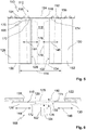
- FIGS Figures 5 and 6 Another exemplary embodiment of a protective device 110 in the form of a protective gate 112 is illustrated.
- the protection device 10 according to the Figures 1 to 4 and the protection device 110 according to FIGS Figures 5 and 6 are basically similar. The following detailed descriptions therefore also apply to the embodiment of the protective device 10 according to FIGS Figures 1 to 4 , and vice versa.
- the protective device 110 is designed as a protective gate 112 in order to selectively open or close an opening 114.
- a closing plane 118 which is delimited by walls (or posts) 120, 122 and an (upper) crossbar 124. Compare this too Fig. 6 .
- a bottom 134 is provided which delimits the opening 114 or the closing plane 118 on the bottom side.
- the protective device 110 has a first closing element 126 and a second closing element 130.
- the first closing element 126 has a closing edge 128.
- the second closing element 130 has a closing edge 132.
- the locking elements 126, 130 are each designed as a door leaf or door leaf. In the embodiment according to the Figures 5 and 6 the locking elements 126, 130 are designed to be sufficiently rigid.
- the closing elements 126, 130 are, for example, plate-shaped.
- the closing edges 128, 132 of the closing elements 126, 130 face each other. In the closed state of the protective device 110, the closing edges can 128, 132 contact each other. At least a remaining distance between the closing edges 128, 132 in the closed state is very small.
- Double arrows 144, 146 illustrate a closing direction or direction of movement of the closing elements 126, 130.
- the closing elements 126, 130 are received on an (upper) horizontal guide 148.
- the closing elements 126, 130 in the exemplary embodiment according to FIGS Figures 5 and 6 no guide or horizontal guide at their lower, free ends 150, 152.
- the closing elements 126, 130 are received on carriages 158, 160 on the horizontal guide 148 and are movably guided.
- the protective device 110 has a monitoring device 168 with a sensor unit 170 for monitoring the closing edges 128, 132 of the closing elements 126, 130.
- the sensor unit 170 has a sensor 172 which is assigned to the closing element 126 or its closing edge 128.
- a sensor 174 is also provided, which is assigned to the closing element 130 or its closing edge 132.
- monitoring areas 176, 178 of the two sensors 172, 174 are indicated by dashed lines.
- the monitoring areas 176, 178 can also be designed to overlap in the direction of movement of the closing elements 126, 130.
- the monitoring areas 176, 178 in FIG Fig. 5 primarily for illustration purposes.
- Fig. 6 illustrates a further conceivable design of the monitoring areas 176, 178.
- sensors 172, 174 are formed on sides of closing plane 118 facing away from one another.
- An offset between the sensors 172, 174 transverse to the closing plane 118 is indicated by 180.
- Fig. 6 also shows that the monitoring areas 176, 178 do not necessarily have to be flat.
- the monitoring areas 176, 178 are, for example, slightly fanned out from the sensors 172, 174 in the direction of the respectively opposite closing edge 128, 132. In this way it is ensured that the closing edges 128, 132 can also be monitored reliably in the event of possible deflections of the closing elements 126, 130 transversely to the closing plane 118, without excessive false alarms occurring.
- the sensor 172 monitors both the (own) closing edge 128 and the (opposite) closing edge 132 on one side of the closing level 118.
- the sensor 174 monitors both the (own) closing edge 132 and the (off) on the opposite side of the closing level closing edge 128 opposite its view).
- the two sensors 172, 174 form two monitoring areas / monitoring levels due to their opposite arrangement in relation to the closing level 118, which enclose the closing level 118 between them. In this way, the operational safety of the protective device 110 can be further increased.
- protective devices 210, 310 are illustrated.
- the protective devices 10, 110 according to the Figures 1 to 6 and the protection devices 210, 310 according to the Figures 7 to 9 are basically similar. The following detailed descriptions therefore also apply to the configurations already illustrated, and vice versa.
- Fig. 7 illustrates in a simplified view from below a design of a protective device 210 in the form of a protective door 212 designed as a roller door.
- the protective device 210 is designed, for example, as a horizontally closing protective door 212.
- the protective gate 212 has posts 220, 222 which are connected to one another via a crossbar 224.
- a closing plane 218 is defined between the posts 220, 222 and the crossbar 224.
- the protective gate 212 has a first closing element 226 with a closing edge 228 and an opposing second closing element 230 with a closing edge 232.
- a drive 238 is provided for driving the closing elements 226, 230. Movements of the closing elements 226, 230 for opening and closing the protective gate 212 are shown in Fig. 7 illustrated by double arrows 244,246.
- a horizontal guide 248 is formed on the crossbeam 224, on which the closing elements 226, 230 are received via slides / carriages.
- the protective device 210 also has a monitoring device 268 which comprises at least one sensor unit 270.
- the sensor unit 270 comprises a first sensor 272, which is assigned to the first closing edge 228 of the first closing element 226.
- the sensor unit 270 in FIG Fig. 7 The exemplary embodiment illustrated a second sensor 274, which is assigned to the second closing edge 232 of the second closing element 230.
- the two sensors 272, 274 are arranged in the closing plane 218.
- the two sensors 272, 274 have monitoring areas 276, 278 which face one another and cover the closing plane 218, at least in the area of the closing edges 228, 232. In this way, the closing edges 228, 232 of the closing elements 226, 230 can be monitored directly.
- FIG. 8 and 9 illustrate in a simplified view from below a design of a protective device 310 in the form of a protective door 312 designed as a folding door.
- the protective device 310 is designed, for example, as a horizontally closing protective door 312.
- the protective gate 312 has posts 320, 322 which are connected to one another via a crossbar 324.
- a closing plane 318 is defined between the posts 320, 322 and the crossbar 324.
- Fig. 8 illustrates a closed state.
- Fig. 9 illustrates a partially opened state of protection device 310.
- the protective device 310 has a first closing element 326 with a first closing edge 328 and a second closing element 330 with a second closing edge 332 on. In the closed representation according to Fig. 8 contact the closing edges 328, 332.
- the movement of the closing elements 326, 330 when opening and closing the protective device 310 is indicated by double arrows 344, 346 in Fig. 9 illustrated.
- a horizontal guide 348 is formed on the crossbar 324, on which the closing elements 326, 330 are received via slides / trolleys. When the closing elements 326, 330 are opened and closed, they are unfolded or folded.
- the protective device 310 has a monitoring device 368 with a sensor unit 370.
- the sensor unit 370 comprises a first sensor 372 and a second sensor 374.
- the first sensor 372 comprises a monitoring area 376.
- the second sensor 374 comprises a monitoring area 378.
- the sensors 372, 374 are in the immediate vicinity of the closing edges 328, 332 on the respective closing element 326, 330 added. In the in the Figures 8 and 9
- the sensors 372, 374 are firmly coupled to the closing elements 326, 330, so that a “visual axis” of the respective monitoring areas 376, 378 changes together with the folding movement of the closing elements 326, 330.
- the sensors 372, 374 are pivoted in relation to the (ideal) closing plane 318 during the folding movement of the closing elements 326, 330 on account of their assignment to the closing edge 328, 332.
- this design also allows direct monitoring of the closing edges 328, 332 when the closing elements 326, 330 are opened and closed.
Landscapes
- Engineering & Computer Science (AREA)
- Structural Engineering (AREA)
- Architecture (AREA)
- Civil Engineering (AREA)
- Power-Operated Mechanisms For Wings (AREA)
- Operating, Guiding And Securing Of Roll- Type Closing Members (AREA)
Applications Claiming Priority (1)
| Application Number | Priority Date | Filing Date | Title |
|---|---|---|---|
| DE102018130531.1A DE102018130531A1 (de) | 2018-11-30 | 2018-11-30 | Schutzvorrichtung, insbesondere Industrietor |
Publications (2)
| Publication Number | Publication Date |
|---|---|
| EP3660251A1 true EP3660251A1 (fr) | 2020-06-03 |
| EP3660251B1 EP3660251B1 (fr) | 2022-05-04 |
Family
ID=68732988
Family Applications (1)
| Application Number | Title | Priority Date | Filing Date |
|---|---|---|---|
| EP19212621.7A Active EP3660251B1 (fr) | 2018-11-30 | 2019-11-29 | Dispositif de protection, en particulier portail industriel |
Country Status (2)
| Country | Link |
|---|---|
| EP (1) | EP3660251B1 (fr) |
| DE (1) | DE102018130531A1 (fr) |
Cited By (3)
| Publication number | Priority date | Publication date | Assignee | Title |
|---|---|---|---|---|
| CN112586964A (zh) * | 2020-12-16 | 2021-04-02 | 宁波星宏智能技术有限公司 | 一种智能窗帘 |
| EP4019729A1 (fr) | 2020-12-24 | 2022-06-29 | Faiveley Transport Tours | Porte d'accès à un véhicule de transport comprenant des moyens de surveillance du déplacement de son ouvrant, véhicule et procédé de pilotage correspondants |
| WO2022203647A1 (fr) * | 2021-03-22 | 2022-09-29 | Hewlett-Packard Development Company, L.P. | Dispositifs de commande de portes automatiques |
Citations (6)
| Publication number | Priority date | Publication date | Assignee | Title |
|---|---|---|---|---|
| EP0939188A2 (fr) * | 1998-01-23 | 1999-09-01 | GEZE GmbH & Co. | Arrangement automatique pour portes et fenêtres |
| DE19804632C2 (de) | 1998-02-05 | 2001-10-11 | Agta Record Ag Fehraltorf | Verfahren und Vorrichtung zur Ansteuerung und/oder Überwachung eines motorisch angetriebenen Flügels |
| US6304178B1 (en) * | 1997-01-20 | 2001-10-16 | Kabushiki Kaisha Tsuden | Door safety system |
| WO2007003176A1 (fr) * | 2005-07-04 | 2007-01-11 | Robert Falk | Systeme de porte |
| DE102008044990A1 (de) | 2008-08-29 | 2010-03-11 | Agtatec Ag | Verfahren und Vorrichtung zur Ansteuerung und/oder Überwachung eines motorisch angetriebenen Flügels während der Öffnungsphase |
| EP2746525A1 (fr) * | 2012-12-19 | 2014-06-25 | ITW Industrietore GmbH | Procédé de commande de l'entraînement d'un volet roulant et dispositif de commande de l'entraînement d'un volet roulant |
-
2018
- 2018-11-30 DE DE102018130531.1A patent/DE102018130531A1/de not_active Withdrawn
-
2019
- 2019-11-29 EP EP19212621.7A patent/EP3660251B1/fr active Active
Patent Citations (6)
| Publication number | Priority date | Publication date | Assignee | Title |
|---|---|---|---|---|
| US6304178B1 (en) * | 1997-01-20 | 2001-10-16 | Kabushiki Kaisha Tsuden | Door safety system |
| EP0939188A2 (fr) * | 1998-01-23 | 1999-09-01 | GEZE GmbH & Co. | Arrangement automatique pour portes et fenêtres |
| DE19804632C2 (de) | 1998-02-05 | 2001-10-11 | Agta Record Ag Fehraltorf | Verfahren und Vorrichtung zur Ansteuerung und/oder Überwachung eines motorisch angetriebenen Flügels |
| WO2007003176A1 (fr) * | 2005-07-04 | 2007-01-11 | Robert Falk | Systeme de porte |
| DE102008044990A1 (de) | 2008-08-29 | 2010-03-11 | Agtatec Ag | Verfahren und Vorrichtung zur Ansteuerung und/oder Überwachung eines motorisch angetriebenen Flügels während der Öffnungsphase |
| EP2746525A1 (fr) * | 2012-12-19 | 2014-06-25 | ITW Industrietore GmbH | Procédé de commande de l'entraînement d'un volet roulant et dispositif de commande de l'entraînement d'un volet roulant |
Cited By (5)
| Publication number | Priority date | Publication date | Assignee | Title |
|---|---|---|---|---|
| CN112586964A (zh) * | 2020-12-16 | 2021-04-02 | 宁波星宏智能技术有限公司 | 一种智能窗帘 |
| CN112586964B (zh) * | 2020-12-16 | 2022-04-08 | 宁波星宏智能技术有限公司 | 一种智能窗帘 |
| EP4019729A1 (fr) | 2020-12-24 | 2022-06-29 | Faiveley Transport Tours | Porte d'accès à un véhicule de transport comprenant des moyens de surveillance du déplacement de son ouvrant, véhicule et procédé de pilotage correspondants |
| FR3118477A1 (fr) * | 2020-12-24 | 2022-07-01 | Faiveley Transport Tours | Porte d’accès à un véhicule de transport comprenant des moyens de surveillance du déplacement de son ouvrant, véhicule et procédé de pilotage correspondants |
| WO2022203647A1 (fr) * | 2021-03-22 | 2022-09-29 | Hewlett-Packard Development Company, L.P. | Dispositifs de commande de portes automatiques |
Also Published As
| Publication number | Publication date |
|---|---|
| DE102018130531A1 (de) | 2020-06-04 |
| EP3660251B1 (fr) | 2022-05-04 |
Similar Documents
| Publication | Publication Date | Title |
|---|---|---|
| EP3584400B1 (fr) | Porte de protection et procédé de fonctionnement d'une porte de protection | |
| EP2404859B1 (fr) | Dispositif de surveillance pour sécuriser un élément entraîné | |
| EP2017524B1 (fr) | Barrière lumineuse | |
| EP3660251B1 (fr) | Dispositif de protection, en particulier portail industriel | |
| DE102008044990A1 (de) | Verfahren und Vorrichtung zur Ansteuerung und/oder Überwachung eines motorisch angetriebenen Flügels während der Öffnungsphase | |
| EP2925947B1 (fr) | Porte roulante présentant un vantail en forme de rideau souple | |
| EP2818620B1 (fr) | Installation de fenêtre ou de porte automatique | |
| EP2345618A1 (fr) | Bordure de sécurité d'une porte de cabine | |
| EP2880468A2 (fr) | Dispositif à grille de lumière, dispositif de sécurité à grille de lumière et portail à entraînement automatique équipé dudit dispositif de sécuité à grille | |
| DE19949329C2 (de) | Schnellauftor | |
| EP1820928A2 (fr) | Porte sectionnelle | |
| DE102010049978A1 (de) | Verfahren zur Überwachung von Bewegungen an einem Rolltor sowie Vorrichtung zur Durchführung des Verfahrens | |
| DE202007014472U1 (de) | Türkonstruktion für einen Aufzug | |
| DE102007033412A1 (de) | Rolltor | |
| DE102012208723A1 (de) | Förderstrecke zum horizontalen Transport von Fördergütern und Verfahren zur Absicherung einer solchen Förderstrecke | |
| EP2444583B1 (fr) | Colonne de portail pour un portail roulant | |
| DE102012112661A1 (de) | Verfahren zur Steuerung des Antriebs eines Rolltors und Vorrichtung zur Steuerung des Antriebs eines Rolltors | |
| EP1195179B1 (fr) | Volet ou porte de sécurité contre le feu ou la fumée | |
| EP4730064A1 (fr) | Système de contrôle d'une transition entre une première zone et une seconde zone dans un environnement de fonctionnement | |
| EP4136306A1 (fr) | Dispositif de sécurité pour une porte de levage et porte de levage équipée d'un tel dispositif de sécurité | |
| DE102004053820B4 (de) | Sensoranordnung für automatische Türanlagen | |
| EP1612363A2 (fr) | Ensemble de porte coulissante automatique | |
| DE102021102866A1 (de) | Rolltoranlage | |
| EP2861811B1 (fr) | Fenêtre, porte ou similaire comprenant un profilé de fermeture | |
| EP2226548A1 (fr) | Dispositif de sécurisation des zones de danger d'une machine |
Legal Events
| Date | Code | Title | Description |
|---|---|---|---|
| PUAI | Public reference made under article 153(3) epc to a published international application that has entered the european phase |
Free format text: ORIGINAL CODE: 0009012 |
|
| STAA | Information on the status of an ep patent application or granted ep patent |
Free format text: STATUS: THE APPLICATION HAS BEEN PUBLISHED |
|
| AK | Designated contracting states |
Kind code of ref document: A1 Designated state(s): AL AT BE BG CH CY CZ DE DK EE ES FI FR GB GR HR HU IE IS IT LI LT LU LV MC MK MT NL NO PL PT RO RS SE SI SK SM TR |
|
| AX | Request for extension of the european patent |
Extension state: BA ME |
|
| STAA | Information on the status of an ep patent application or granted ep patent |
Free format text: STATUS: REQUEST FOR EXAMINATION WAS MADE |
|
| 17P | Request for examination filed |
Effective date: 20201203 |
|
| RBV | Designated contracting states (corrected) |
Designated state(s): AL AT BE BG CH CY CZ DE DK EE ES FI FR GB GR HR HU IE IS IT LI LT LU LV MC MK MT NL NO PL PT RO RS SE SI SK SM TR |
|
| GRAP | Despatch of communication of intention to grant a patent |
Free format text: ORIGINAL CODE: EPIDOSNIGR1 |
|
| STAA | Information on the status of an ep patent application or granted ep patent |
Free format text: STATUS: GRANT OF PATENT IS INTENDED |
|
| INTG | Intention to grant announced |
Effective date: 20211124 |
|
| RIN1 | Information on inventor provided before grant (corrected) |
Inventor name: DRESSLER, HANS-JUERGEN |
|
| GRAS | Grant fee paid |
Free format text: ORIGINAL CODE: EPIDOSNIGR3 |
|
| GRAA | (expected) grant |
Free format text: ORIGINAL CODE: 0009210 |
|
| STAA | Information on the status of an ep patent application or granted ep patent |
Free format text: STATUS: THE PATENT HAS BEEN GRANTED |
|
| AK | Designated contracting states |
Kind code of ref document: B1 Designated state(s): AL AT BE BG CH CY CZ DE DK EE ES FI FR GB GR HR HU IE IS IT LI LT LU LV MC MK MT NL NO PL PT RO RS SE SI SK SM TR |
|
| REG | Reference to a national code |
Ref country code: GB Ref legal event code: FG4D Free format text: NOT ENGLISH |
|
| REG | Reference to a national code |
Ref country code: CH Ref legal event code: EP |
|
| REG | Reference to a national code |
Ref country code: AT Ref legal event code: REF Ref document number: 1489211 Country of ref document: AT Kind code of ref document: T Effective date: 20220515 |
|
| REG | Reference to a national code |
Ref country code: IE Ref legal event code: FG4D Free format text: LANGUAGE OF EP DOCUMENT: GERMAN Ref country code: DE Ref legal event code: R096 Ref document number: 502019004257 Country of ref document: DE |
|
| REG | Reference to a national code |
Ref country code: LT Ref legal event code: MG9D |
|
| REG | Reference to a national code |
Ref country code: NL Ref legal event code: MP Effective date: 20220504 |
|
| PG25 | Lapsed in a contracting state [announced via postgrant information from national office to epo] |
Ref country code: SE Free format text: LAPSE BECAUSE OF FAILURE TO SUBMIT A TRANSLATION OF THE DESCRIPTION OR TO PAY THE FEE WITHIN THE PRESCRIBED TIME-LIMIT Effective date: 20220504 Ref country code: PT Free format text: LAPSE BECAUSE OF FAILURE TO SUBMIT A TRANSLATION OF THE DESCRIPTION OR TO PAY THE FEE WITHIN THE PRESCRIBED TIME-LIMIT Effective date: 20220905 Ref country code: NO Free format text: LAPSE BECAUSE OF FAILURE TO SUBMIT A TRANSLATION OF THE DESCRIPTION OR TO PAY THE FEE WITHIN THE PRESCRIBED TIME-LIMIT Effective date: 20220804 Ref country code: NL Free format text: LAPSE BECAUSE OF FAILURE TO SUBMIT A TRANSLATION OF THE DESCRIPTION OR TO PAY THE FEE WITHIN THE PRESCRIBED TIME-LIMIT Effective date: 20220504 Ref country code: LT Free format text: LAPSE BECAUSE OF FAILURE TO SUBMIT A TRANSLATION OF THE DESCRIPTION OR TO PAY THE FEE WITHIN THE PRESCRIBED TIME-LIMIT Effective date: 20220504 Ref country code: HR Free format text: LAPSE BECAUSE OF FAILURE TO SUBMIT A TRANSLATION OF THE DESCRIPTION OR TO PAY THE FEE WITHIN THE PRESCRIBED TIME-LIMIT Effective date: 20220504 Ref country code: GR Free format text: LAPSE BECAUSE OF FAILURE TO SUBMIT A TRANSLATION OF THE DESCRIPTION OR TO PAY THE FEE WITHIN THE PRESCRIBED TIME-LIMIT Effective date: 20220805 Ref country code: FI Free format text: LAPSE BECAUSE OF FAILURE TO SUBMIT A TRANSLATION OF THE DESCRIPTION OR TO PAY THE FEE WITHIN THE PRESCRIBED TIME-LIMIT Effective date: 20220504 Ref country code: ES Free format text: LAPSE BECAUSE OF FAILURE TO SUBMIT A TRANSLATION OF THE DESCRIPTION OR TO PAY THE FEE WITHIN THE PRESCRIBED TIME-LIMIT Effective date: 20220504 Ref country code: BG Free format text: LAPSE BECAUSE OF FAILURE TO SUBMIT A TRANSLATION OF THE DESCRIPTION OR TO PAY THE FEE WITHIN THE PRESCRIBED TIME-LIMIT Effective date: 20220804 |
|
| PG25 | Lapsed in a contracting state [announced via postgrant information from national office to epo] |
Ref country code: RS Free format text: LAPSE BECAUSE OF FAILURE TO SUBMIT A TRANSLATION OF THE DESCRIPTION OR TO PAY THE FEE WITHIN THE PRESCRIBED TIME-LIMIT Effective date: 20220504 Ref country code: PL Free format text: LAPSE BECAUSE OF FAILURE TO SUBMIT A TRANSLATION OF THE DESCRIPTION OR TO PAY THE FEE WITHIN THE PRESCRIBED TIME-LIMIT Effective date: 20220504 Ref country code: LV Free format text: LAPSE BECAUSE OF FAILURE TO SUBMIT A TRANSLATION OF THE DESCRIPTION OR TO PAY THE FEE WITHIN THE PRESCRIBED TIME-LIMIT Effective date: 20220504 Ref country code: IS Free format text: LAPSE BECAUSE OF FAILURE TO SUBMIT A TRANSLATION OF THE DESCRIPTION OR TO PAY THE FEE WITHIN THE PRESCRIBED TIME-LIMIT Effective date: 20220904 |
|
| PG25 | Lapsed in a contracting state [announced via postgrant information from national office to epo] |
Ref country code: SM Free format text: LAPSE BECAUSE OF FAILURE TO SUBMIT A TRANSLATION OF THE DESCRIPTION OR TO PAY THE FEE WITHIN THE PRESCRIBED TIME-LIMIT Effective date: 20220504 Ref country code: SK Free format text: LAPSE BECAUSE OF FAILURE TO SUBMIT A TRANSLATION OF THE DESCRIPTION OR TO PAY THE FEE WITHIN THE PRESCRIBED TIME-LIMIT Effective date: 20220504 Ref country code: RO Free format text: LAPSE BECAUSE OF FAILURE TO SUBMIT A TRANSLATION OF THE DESCRIPTION OR TO PAY THE FEE WITHIN THE PRESCRIBED TIME-LIMIT Effective date: 20220504 Ref country code: EE Free format text: LAPSE BECAUSE OF FAILURE TO SUBMIT A TRANSLATION OF THE DESCRIPTION OR TO PAY THE FEE WITHIN THE PRESCRIBED TIME-LIMIT Effective date: 20220504 Ref country code: DK Free format text: LAPSE BECAUSE OF FAILURE TO SUBMIT A TRANSLATION OF THE DESCRIPTION OR TO PAY THE FEE WITHIN THE PRESCRIBED TIME-LIMIT Effective date: 20220504 Ref country code: CZ Free format text: LAPSE BECAUSE OF FAILURE TO SUBMIT A TRANSLATION OF THE DESCRIPTION OR TO PAY THE FEE WITHIN THE PRESCRIBED TIME-LIMIT Effective date: 20220504 |
|
| REG | Reference to a national code |
Ref country code: DE Ref legal event code: R097 Ref document number: 502019004257 Country of ref document: DE |
|
| PLBE | No opposition filed within time limit |
Free format text: ORIGINAL CODE: 0009261 |
|
| STAA | Information on the status of an ep patent application or granted ep patent |
Free format text: STATUS: NO OPPOSITION FILED WITHIN TIME LIMIT |
|
| PG25 | Lapsed in a contracting state [announced via postgrant information from national office to epo] |
Ref country code: AL Free format text: LAPSE BECAUSE OF FAILURE TO SUBMIT A TRANSLATION OF THE DESCRIPTION OR TO PAY THE FEE WITHIN THE PRESCRIBED TIME-LIMIT Effective date: 20220504 |
|
| 26N | No opposition filed |
Effective date: 20230207 |
|
| PG25 | Lapsed in a contracting state [announced via postgrant information from national office to epo] |
Ref country code: SI Free format text: LAPSE BECAUSE OF FAILURE TO SUBMIT A TRANSLATION OF THE DESCRIPTION OR TO PAY THE FEE WITHIN THE PRESCRIBED TIME-LIMIT Effective date: 20220504 |
|
| P01 | Opt-out of the competence of the unified patent court (upc) registered |
Effective date: 20230513 |
|
| PG25 | Lapsed in a contracting state [announced via postgrant information from national office to epo] |
Ref country code: MC Free format text: LAPSE BECAUSE OF FAILURE TO SUBMIT A TRANSLATION OF THE DESCRIPTION OR TO PAY THE FEE WITHIN THE PRESCRIBED TIME-LIMIT Effective date: 20220504 |
|
| PG25 | Lapsed in a contracting state [announced via postgrant information from national office to epo] |
Ref country code: LU Free format text: LAPSE BECAUSE OF NON-PAYMENT OF DUE FEES Effective date: 20221129 |
|
| PG25 | Lapsed in a contracting state [announced via postgrant information from national office to epo] |
Ref country code: IE Free format text: LAPSE BECAUSE OF NON-PAYMENT OF DUE FEES Effective date: 20221129 |
|
| PG25 | Lapsed in a contracting state [announced via postgrant information from national office to epo] |
Ref country code: FR Free format text: LAPSE BECAUSE OF NON-PAYMENT OF DUE FEES Effective date: 20221130 |
|
| PG25 | Lapsed in a contracting state [announced via postgrant information from national office to epo] |
Ref country code: IT Free format text: LAPSE BECAUSE OF FAILURE TO SUBMIT A TRANSLATION OF THE DESCRIPTION OR TO PAY THE FEE WITHIN THE PRESCRIBED TIME-LIMIT Effective date: 20220504 |
|
| PG25 | Lapsed in a contracting state [announced via postgrant information from national office to epo] |
Ref country code: HU Free format text: LAPSE BECAUSE OF FAILURE TO SUBMIT A TRANSLATION OF THE DESCRIPTION OR TO PAY THE FEE WITHIN THE PRESCRIBED TIME-LIMIT; INVALID AB INITIO Effective date: 20191129 |
|
| PG25 | Lapsed in a contracting state [announced via postgrant information from national office to epo] |
Ref country code: CY Free format text: LAPSE BECAUSE OF FAILURE TO SUBMIT A TRANSLATION OF THE DESCRIPTION OR TO PAY THE FEE WITHIN THE PRESCRIBED TIME-LIMIT Effective date: 20220504 |
|
| PG25 | Lapsed in a contracting state [announced via postgrant information from national office to epo] |
Ref country code: MK Free format text: LAPSE BECAUSE OF FAILURE TO SUBMIT A TRANSLATION OF THE DESCRIPTION OR TO PAY THE FEE WITHIN THE PRESCRIBED TIME-LIMIT Effective date: 20220504 |
|
| PG25 | Lapsed in a contracting state [announced via postgrant information from national office to epo] |
Ref country code: TR Free format text: LAPSE BECAUSE OF FAILURE TO SUBMIT A TRANSLATION OF THE DESCRIPTION OR TO PAY THE FEE WITHIN THE PRESCRIBED TIME-LIMIT Effective date: 20220504 |
|
| PG25 | Lapsed in a contracting state [announced via postgrant information from national office to epo] |
Ref country code: MT Free format text: LAPSE BECAUSE OF FAILURE TO SUBMIT A TRANSLATION OF THE DESCRIPTION OR TO PAY THE FEE WITHIN THE PRESCRIBED TIME-LIMIT Effective date: 20220504 |
|
| PG25 | Lapsed in a contracting state [announced via postgrant information from national office to epo] |
Ref country code: BG Free format text: LAPSE BECAUSE OF FAILURE TO SUBMIT A TRANSLATION OF THE DESCRIPTION OR TO PAY THE FEE WITHIN THE PRESCRIBED TIME-LIMIT Effective date: 20220504 |
|
| PG25 | Lapsed in a contracting state [announced via postgrant information from national office to epo] |
Ref country code: BG Free format text: LAPSE BECAUSE OF FAILURE TO SUBMIT A TRANSLATION OF THE DESCRIPTION OR TO PAY THE FEE WITHIN THE PRESCRIBED TIME-LIMIT Effective date: 20220504 |
|
| REG | Reference to a national code |
Ref country code: CH Ref legal event code: U11 Free format text: ST27 STATUS EVENT CODE: U-0-0-U10-U11 (AS PROVIDED BY THE NATIONAL OFFICE) Effective date: 20251201 |
|
| PGFP | Annual fee paid to national office [announced via postgrant information from national office to epo] |
Ref country code: DE Payment date: 20251126 Year of fee payment: 7 |
|
| PGFP | Annual fee paid to national office [announced via postgrant information from national office to epo] |
Ref country code: GB Payment date: 20251121 Year of fee payment: 7 |
|
| PGFP | Annual fee paid to national office [announced via postgrant information from national office to epo] |
Ref country code: AT Payment date: 20251120 Year of fee payment: 7 |
|
| PGFP | Annual fee paid to national office [announced via postgrant information from national office to epo] |
Ref country code: BE Payment date: 20251119 Year of fee payment: 7 |
|
| PGFP | Annual fee paid to national office [announced via postgrant information from national office to epo] |
Ref country code: CH Payment date: 20251201 Year of fee payment: 7 |