EP3660262B1 - Dichtungsschaft - Google Patents
Dichtungsschaft Download PDFInfo
- Publication number
- EP3660262B1 EP3660262B1 EP19219493.4A EP19219493A EP3660262B1 EP 3660262 B1 EP3660262 B1 EP 3660262B1 EP 19219493 A EP19219493 A EP 19219493A EP 3660262 B1 EP3660262 B1 EP 3660262B1
- Authority
- EP
- European Patent Office
- Prior art keywords
- seal
- ring
- bore receptacle
- polished bore
- sealing apparatus
- Prior art date
- Legal status (The legal status is an assumption and is not a legal conclusion. Google has not performed a legal analysis and makes no representation as to the accuracy of the status listed.)
- Active
Links
Images



Classifications
-
- E—FIXED CONSTRUCTIONS
- E21—EARTH OR ROCK DRILLING; MINING
- E21B—EARTH OR ROCK DRILLING; OBTAINING OIL, GAS, WATER, SOLUBLE OR MELTABLE MATERIALS OR A SLURRY OF MINERALS FROM WELLS
- E21B43/00—Methods or apparatus for obtaining oil, gas, water, soluble or meltable materials or a slurry of minerals from wells
- E21B43/02—Subsoil filtering
- E21B43/10—Setting of casings, screens, liners or the like in wells
-
- E—FIXED CONSTRUCTIONS
- E21—EARTH OR ROCK DRILLING; MINING
- E21B—EARTH OR ROCK DRILLING; OBTAINING OIL, GAS, WATER, SOLUBLE OR MELTABLE MATERIALS OR A SLURRY OF MINERALS FROM WELLS
- E21B17/00—Drilling rods or pipes; Flexible drill strings; Kellies; Drill collars; Sucker rods; Cables; Casings; Tubings
- E21B17/02—Couplings; joints
- E21B17/08—Casing joints
-
- E—FIXED CONSTRUCTIONS
- E21—EARTH OR ROCK DRILLING; MINING
- E21B—EARTH OR ROCK DRILLING; OBTAINING OIL, GAS, WATER, SOLUBLE OR MELTABLE MATERIALS OR A SLURRY OF MINERALS FROM WELLS
- E21B33/00—Sealing or packing boreholes or wells
- E21B33/10—Sealing or packing boreholes or wells in the borehole
- E21B33/12—Packers; Plugs
- E21B33/1208—Packers; Plugs characterised by the construction of the sealing or packing means
Definitions
- the present invention generally relates to a downhole seal arrangement.
- FIG. 1 shows a seal stem disposed inside a polish bore receptacle 3 ("PBR") of the liner.
- the seal stem includes a mandrel 10 and three assemblies 11, 12, 13 of Chevron-type seal rings disposed on a reduced diameter portion of the mandrel 10.
- Each assembly 11, 12, 13 includes upper and lower travel stops 14, 16 attached to the mandrel 10.
- Two stacks of oppositely facing Chevron-type seal rings 21, 23 are disposed between the travel stops 14, 16.
- a stack of upwardly oriented seal rings 21 and a stack of downwardly oriented seal rings 22 are disposed on each side of an o-ring 23.
- Each stack may include as many as twenty seal rings 21, 22 to provide adequate sealing with the PBR.
- the Chevron seal rings 21, 22 are oriented in opposite directions to seal against differential pressures in either direction.
- One of the drawbacks of this design is a reduced diameter portion 8 is created to accommodate the seal assemblies 11, 12, 13.
- the reduced diameter portion 8 decreases the burst and collapse integrity of the mandrel 10.
- Another drawback is one or more of the seals may roll off the seal stem during insertion, removal, or circulation.
- CA 2 121 178 A1 discloses a wellhead seal assembly for sealing between a first pipe member and a second pipe member.
- the first pipe member has an inside diameter and the second pipe member has an outside diameter which is smaller than the inside diameter.
- the pipe members are arranged such that the second pipe member is positioned, at least partly, generally concentrically within the first pipe member so that an annular gap of approximately a first distance exists between the first and second pipe members.
- the seal assembly comprises: an annular elastomeric body having, in cross-section, a generally rectangular shape comprising a first flat radial surface, a second flat radial surface, an inner axial surface, and an outer axial surface; each of the first and second flat radial surfaces has an inner end and an outer end.
- US 4 046 405 A discloses a method and apparatus for the installation of a casing hanger supporting a string of casing downhole in an oil or gas well, for removal of the installation equipment, and for tying back the hanger to an insulated production riser extending to the surface.
- US 3 225 566 A discloses a drill string shock absorber for use in a rotary well drilling string.
- a sealing apparatus for sealing against an inner surface of a polished bore receptacle is provided in accordance with appended claim 1.
- the present disclosure generally relates to a seal assembly for a downhole tool.
- the seal assembly will be described herein in relation to a seal stem for reconnecting to a tubular such as a liner. It is to be understood, however, that the seal assembly may also be used with other downhole tools. Further, the seal assembly may be used in a downhole tool that is disposed within a cased wellbore or within an open-hole wellbore.
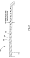
- Figure 2 illustrates an example of a seal stem 100, not according to the invention.
- the seal stem 100 may be a tubular connected to a tubular string (not shown) such as a tubing string. In another example, the seal stem 100 may be integral with the tubular string.
- the seal stem 100 includes a mandrel 110 and one or more seal assemblies.
- the seal stem 100 may be adapted to form a seal with a tubular in the wellbore.
- the seal stem 100 may engage a precise bore tubular such as a polish bore receptacle ("PBR").
- PBR polish bore receptacle
- the precise bore tubular may include a tubular having a bore machined to a smooth finish, to a predetermined diameter, or both.
- PBR polish bore receptacle
- the seal stem 100 may include any suitable number of seal assemblies 120 to create a seal between mandrel 110 and the PBR.
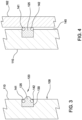
- Figure 3 is an enlarged view of an exemplary seal assembly 120.
- the seal assembly 120 includes a seal ring 125 disposed in a gland 130.
- the gland 130 may be a circumferential groove formed in the outer surface of the mandrel 110. Because the wall thickness of the mandrel 110 on each side of the seal ring 125 is retained, as indicated by reference number 108, the burst and/or collapse properties of the mandrel 110 remain substantially the same.
- the seal assemblies 120 may be molded and bonded to the gland 120.
- a bonding material such as glue, fastener, or other attachment means, may optionally be used to attach the seal ring 125 to the gland 130. Bonding the seal ring 125 in the gland 130 is useful to prevent the seal ring 125 from becoming unstable and swab off during movement of the seal stem 100.
- the seal ring 125 may include an elastomeric material such as poly ether ketone ("PEEK”), polytetrafluoroethylene (“PTFE”), and combinations thereof.
- a volume gap (not shown) may be created between the seal ring 125 and a side of the gland 130. The volume gap is configured to substantially prevent distortion of the seal ring 125 as the seal stem 100 is being inserted into the PBR 162.
- the seal ring 125 includes one or more anti-extrusion bands, such as a first seal band 141 (first anti-extrusion band) and a second seal band 142 (second anti-extrusion band). As shown, the seal bands 141, 142 are embedded in the seal ring 125 in an upper corner of each side of the seal ring 125. In one example, the seal bands 141, 142 are disposed on an outer circumference of the seal ring 125. In another embodiment, the seal bands may be a non-elastomeric anti-extrusion band for supporting high pressure. In yet another example, the seal bands 141, 142 are springs, such as toroidal coil springs. The seal bands 141, 142 may be used to limit the extrusion of the seal ring 125 during expansion of the seal assembly 120. The seal bands 141, 142 may also be used to limit the extrusion of applied differential pressure after expansion of the seal assembly 120.
- Figure 4 shows the seal stem 100 engaged with the PBR 162.
- the seal ring 125 changes its configuration and occupies a portion of the gap 145 between the mandrel 110 and the PBR 162.
- the seal ring 125 includes a protrusion for contact with the PBR 162.
- the protrusion may be any suitable shape such as an arcuate shape, a contour, or double protrusion.
- the protrusion has a height above the mandrel 110 that is more than the distance of the gap 145.
- Engagement with the PBR 162 causes the elastomeric material of the seal ring 125 to redistribute along the gap 145 between mandrel 110 and the PBR 162.
- the seal bands 141, 142 are springs, such as toroidal coil springs, which expand radially outward into the gap 145 due to the redistribution of the elastomeric material. As the springs expand radially outward, the coils of spring act as a barrier to the flow of the elastomeric material of the seal ring 125. In this manner, the seal bands 141, 142 in the seal ring 125 act as an anti-extrusion barriers.
- seal assemblies 120 described herein provide several advantages over the prior art. For example, by preventing extrusion of the seal ring 125, the seal bands 141, 142 retain the seal ring 125 in an energized state to create a high-pressure seal between the seal assembly 120 and the PBR 162.
- the seal assembly 120 may create a high-pressure seal in the range of 83 to 97 MPa (12,000 to 14,000 psi).
- Another potential benefit is the seal assembly 120 does not require the mandrel 110 to include a reduced diameter portion to accommodate the seal assembly. As a result, the mandrel 110 has a higher burst and collapse property.
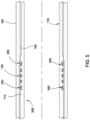
- FIG. 5 illustrates an embodiment of a seal stem 200 according to the invention.
- the seal stem 200 includes the mandrel 110 and the seal assemblies 120.
- Each seal assembly 120 may include the first seal band 141 (first anti-extrusion band) and the second seal band 142 (second anti-extrusion band) as described herein.
- the seal stem 200 includes a wiper ring 250 disposed adjacent each end of the seal assemblies 120.
- the wiper ring 250 is configured to wipe (or clean) an inner surface 165 of the PBR 162 as the wiper ring 250 contacts and slides along the inner surface 165 when the seal stem 200 is inserted into the PBR 162.
- An o-ring 245 is placed under the wiper ring 250.
- the o-ring 245 is configured to act as a stiffener under the wiper ring 250. In other words, the o-ring 245 stiffens the wiper ring 250 by supporting a portion of the wiper ring 250.
- the wiper ring 250 is disposed in a gland 240.
- the gland 240 is a circumferential groove formed in the outer surface of the mandrel 110.
- the gland 240 is shaped so as to provide support to the wiper ring 250 as the wiper ring 250 cleans the inner surface 165 of the PBR 162.
- a volume gap 220 is created between the seal ring 125 and a side of the gland 130.
- the volume gap 220 is used to substantially prevent distortion of the seal ring 125 as the seal stem 200 is being inserted into the PBR 162.
- the volume gap 220 is a free-space (empty space, clearance or void) between a portion of the seal ring 125 and a portion of the gland 130 prior to the insertion of the seal stem 200 into the PBR 162.
- the volume gap 220 is created by positioning the seal ring 125 within the gland 130 such that the seal ring 125 is spaced apart from at least one side of the gland 130.
- volume gap 220 in Figure 6 is created by having a side of the gland 130 arranged parallel to the a side of the seal ring 125, the volume gap 220 may be created in any configuration, such as positioned at an angle, without departing from principles of the present invention. Additionally, the size of the volume gap 220 may vary depending on the configuration of the gland 130. In one embodiment, the gland 130 has 3-5% more volume due to the volume gap 220 than a standard gland without a volume gap.
- the seal ring 125 moves into contact with the inner surface 165 of the PBR 162 to create a seal between the seal stem 200 and the PBR 162.
- the seal ring 125 changes configuration and occupies a portion of the volume gap 220.
- the volume gap 220 is located on the side of the seal assembly 120 which is the first portion to be in contact with the inner surface 165 of the PBR 162. The location of the volume gap 220 in the seal assembly 120 allows the seal ring 125 to change position (or reconfigure) within the gland 130 during the insertion operation. Additionally, the volume of the volume gap 220 may change during the insertion operation.
- Figure 7 illustrates an example of a seal stem 300, not according to the invention.
- the components in the seal stem 300 that are similar to the components in the seal stems 100, 200 will be labeled with the same reference number.
- the seal stem 300 includes multiple sets of seal assemblies 120 on the mandrel 110. Each set includes two seal assemblies 120. It should be understood, however, that each set may include any number of seal assemblies.
- Figure 8 illustrates an enlarged partial view of the seal stem 300 of Figure 7 .
- the seal ring 125 includes one or more anti-extrusion bands, such as the first seal band 141 (first anti-extrusion band) and the second seal band 142 (second anti-extrusion band).
- the seal bands 141, 142 are embedded in the seal ring 125 in an upper corner of each side of the seal ring 125.
- the seal ring 125 is disposed in the gland 130.
- the volume gap 220 may be created between the seal ring 125 and the side of the gland 130. The volume gap is configured to substantially prevent distortion of the seal ring 125 as the seal stem 300 is being inserted into the PBR (not shown).
- the mandrel 110 has a first outer diameter 325 between each set of seal assemblies 120 and a second outer diameter 310 at the seal assemblies 120.
- the first outer diameter 325 is smaller than the second outer diameter 310.
- the mandrel 110 has a greater wall thickness (see reference number 310) at the seal assemblies 120 as compared to the wall thickness (see reference number 325) between each set of seal assemblies 120.
- the increased wall thickness at the seal assemblies 120 provides support to the seal assemblies 120 as the seal stem 300 is being inserted into the PBR (not shown). Further, the increased wall thickness at the seal assemblies 120 minimizes the gap (reference number 145 on Figure 4 ) between the mandrel 110 and the PBR.
- the smaller gap may be used to limit the extrusion of the seal ring 125 as the seal stem 300 is being inserted into the PBR.
- the smaller gap may also be used to limit the extrusion of the seal ring 125 when the seal assemblies 120 are subjected to high differential pressure after the seal stem 300 has been inserted into the PBR.
- the seal assemblies 120 will be able to withstand a higher differential pressure above and/or below the seal assemblies 120 with the smaller gap, as described herein, as compared to seal assemblies that do not have the smaller gap.
- the smaller diameter 325 between each set of seal assemblies 120 increases the clearance between the seal stem 300 and the PBR along a substantial portion of the seal stem 300. The increased clearance between the seal stem 300 and the PBR minimizes the risk of the seal stem 300 of becoming stuck (or jammed) when the seal stem 300 is being inserted into the PBR.
Landscapes
- Engineering & Computer Science (AREA)
- Geology (AREA)
- Life Sciences & Earth Sciences (AREA)
- Mining & Mineral Resources (AREA)
- Physics & Mathematics (AREA)
- Environmental & Geological Engineering (AREA)
- Fluid Mechanics (AREA)
- General Life Sciences & Earth Sciences (AREA)
- Geochemistry & Mineralogy (AREA)
- Mechanical Engineering (AREA)
- Gasket Seals (AREA)
- Joints With Sleeves (AREA)
- Mechanical Sealing (AREA)
Claims (7)
- Dichtungsvorrichtung (200) zum Abdichten gegen eine Innenfläche einer polierten Bohrungsaufnahme (162) in einem Bohrloch, wobei die Dichtungsvorrichtung (200) Folgendes umfasst:eine Spindel (110) mit einer oder mehreren Dichtungsanordnungen (120), wobei jede Dichtungsanordnung (120) in einer jeweiligen Umfangsdichtungsnut (130) angeordnet ist, die in einer Außenfläche der Spindel (110) ausgebildet ist;zwei Abstreifringe (250), wobei jeder Abstreifring (250) in einer jeweiligen umlaufenden Abstreifringnut (240) angeordnet ist, die in der Außenfläche der Spindel (110) ausgebildet ist, wobei jeder Abstreifring (250) konfiguriert ist, um die Innenfläche der polierten Bohrungsaufnahme (162) abzustreifen, wenn die Spindel (110) in die polierte Bohrungsaufnahme (162) eingeführt wird;wobei jede Dichtungsanordnung (120) der einen oder mehreren Dichtungsanordnungen (120) einen Dichtungsring (125) mit einem oder mehreren Anti-Extrusionsbändern (141, 142) umfasst, die in den Dichtungsring (125) eingebettet sind, wobei jeder Dichtungsring (125) konfiguriert ist, um während des Einsetzens der Dichtungsvorrichtung (200) in die polierte Bohrungsaufnahme (162) mit der Innenfläche der polierten Bohrungsaufnahme (162) in Kontakt zu treten und diese abzudichten;wobei in jeder Dichtungsnut (130) ein Volumenspalt (220) zwischen einer Seite jedes Dichtungsrings (125) und einer Seite der jeweiligen Dichtungsnut (130) definiert ist;wobei jeder Abstreifring (250) derart angeordnet ist, dass jede Dichtungsanordnung (120) in Längsrichtung zwischen den zwei Abstreifringen (250) angeordnet ist; undwobei in jeder Abstreifringnut (240) ein jeweiliger O-Ring (245) radial unter jedem Abstreifring (250) angeordnet ist.
- Dichtungsvorrichtung (200) nach Anspruch 1, wobei jede Dichtungsnut (130) aufgrund jedes Volumenspalts (220) 3-5% mehr Volumen hat als eine Nut ohne Volumenspalt.
- Dichtungsvorrichtung (200) nach Anspruch 1, wobei während des Einsetzens der Dichtungsvorrichtung (200) in die polierte Bohrungsaufnahme (162) jeder Dichtungsring (125) seine Konfiguration ändert und einen Abschnitt jedes jeweiligen Volumenspalts (220) einnimmt, wenn jeder Dichtungsring (125) die Innenfläche (165) der polierten Bohrungsaufnahme (162) kontaktiert, um eine Dichtung zwischen jeder Dichtungsanordnung (120) und der polierten Bohrungsaufnahme (162) zu erzeugen.
- Dichtungsvorrichtung (200) nach einem der vorhergehenden Ansprüche, wobei jeder O-Ring (245) jeden jeweiligen Abstreifring (250) versteift, indem er einen Abschnitt jedes jeweiligen Abstreifrings (250) stützt.
- Dichtungsvorrichtung (200) nach einem der vorhergehenden Ansprüche, wobei jede Abstreifringnut (240) so geformt ist, dass sie eine Abstützung für jeden jeweiligen Abstreifring (250) bereitstellt.
- Verfahren zum Erzeugen einer Dichtung zwischen einer Dichtungsvorrichtung (200) nach einem der vorhergehenden Ansprüche und einer polierten Bohrungsaufnahme (162), umfassend:Einsetzen der Dichtungsvorrichtung (200) in die polierte Bohrungsaufnahme (162);Reinigen einer Innenfläche der polierten Bohrungsaufnahme (162), wenn ein führender der beiden Abstreifringe (250) der Dichtungsvorrichtung (200) die Innenfläche der polierten Bohrungsaufnahme (162) kontaktiert, wenn die Dichtungsvorrichtung (200) in die polierte Bohrungsaufnahme (162) eingesetzt wird; undErzeugen der Dichtung zwischen der Dichtungsvorrichtung (200) und der polierten Bohrungsaufnahme (162), wenn die eine oder die mehreren Dichtungsanordnungen (120) mit der Innenfläche der polierten Bohrungsaufnahme (162) in Eingriff kommen, wenn die Dichtungsvorrichtung (200) in die polierte Bohrungsaufnahme (162) eingesetzt wird.
- Verfahren nach Anspruch 6, wobei während des Einsetzens der Dichtungsvorrichtung (200) in die polierte Bohrungsaufnahme (162), wenn jeder Dichtungsring (125) die Innenfläche der polierten Bohrungsaufnahme (162) kontaktiert, jeder Dichtungsring (125) seine Konfiguration ändert und einen Abschnitt jedes jeweiligen Volumenspalts (220) einnimmt.
Applications Claiming Priority (4)
| Application Number | Priority Date | Filing Date | Title |
|---|---|---|---|
| US201261642340P | 2012-05-03 | 2012-05-03 | |
| US13/837,881 US9260926B2 (en) | 2012-05-03 | 2013-03-15 | Seal stem |
| EP13723620.4A EP2844824B1 (de) | 2012-05-03 | 2013-05-03 | Dichtungsschaft |
| PCT/US2013/039417 WO2013166359A2 (en) | 2012-05-03 | 2013-05-03 | Seal stem |
Related Parent Applications (2)
| Application Number | Title | Priority Date | Filing Date |
|---|---|---|---|
| EP13723620.4A Division-Into EP2844824B1 (de) | 2012-05-03 | 2013-05-03 | Dichtungsschaft |
| EP13723620.4A Division EP2844824B1 (de) | 2012-05-03 | 2013-05-03 | Dichtungsschaft |
Publications (2)
| Publication Number | Publication Date |
|---|---|
| EP3660262A1 EP3660262A1 (de) | 2020-06-03 |
| EP3660262B1 true EP3660262B1 (de) | 2023-05-24 |
Family
ID=49511678
Family Applications (2)
| Application Number | Title | Priority Date | Filing Date |
|---|---|---|---|
| EP19219493.4A Active EP3660262B1 (de) | 2012-05-03 | 2013-05-03 | Dichtungsschaft |
| EP13723620.4A Active EP2844824B1 (de) | 2012-05-03 | 2013-05-03 | Dichtungsschaft |
Family Applications After (1)
| Application Number | Title | Priority Date | Filing Date |
|---|---|---|---|
| EP13723620.4A Active EP2844824B1 (de) | 2012-05-03 | 2013-05-03 | Dichtungsschaft |
Country Status (7)
| Country | Link |
|---|---|
| US (1) | US9260926B2 (de) |
| EP (2) | EP3660262B1 (de) |
| AU (3) | AU2013256104B2 (de) |
| BR (1) | BR112014027295B1 (de) |
| CA (1) | CA2872152C (de) |
| PL (1) | PL2844824T3 (de) |
| WO (1) | WO2013166359A2 (de) |
Families Citing this family (28)
| Publication number | Priority date | Publication date | Assignee | Title |
|---|---|---|---|---|
| US11215021B2 (en) | 2011-02-16 | 2022-01-04 | Weatherford Technology Holdings, Llc | Anchoring and sealing tool |
| AU2012217608B2 (en) * | 2011-02-16 | 2016-05-12 | Weatherford Technology Holdings, Llc | Anchoring seal |
| US9528352B2 (en) * | 2011-02-16 | 2016-12-27 | Weatherford Technology Holdings, Llc | Extrusion-resistant seals for expandable tubular assembly |
| CA2827460C (en) | 2011-02-16 | 2017-04-04 | Weatherford/Lamb, Inc. | Downhole tool having expandable annular member |
| US20120205092A1 (en) * | 2011-02-16 | 2012-08-16 | George Givens | Anchoring and sealing tool |
| US20130043657A1 (en) * | 2011-08-18 | 2013-02-21 | Cameron International Corporation | S-seal |
| US9260926B2 (en) | 2012-05-03 | 2016-02-16 | Weatherford Technology Holdings, Llc | Seal stem |
| US9963395B2 (en) | 2013-12-11 | 2018-05-08 | Baker Hughes, A Ge Company, Llc | Methods of making carbon composites |
| US9732580B2 (en) * | 2014-07-29 | 2017-08-15 | Baker Hughes Incorporated | Self-boosting expandable seal with cantilevered seal arm |
| WO2016019110A2 (en) * | 2014-08-01 | 2016-02-04 | Utex Industries, Inc. | High pressure seal with composite anti-extrusion mechanism |
| US9325012B1 (en) | 2014-09-17 | 2016-04-26 | Baker Hughes Incorporated | Carbon composites |
| US10315922B2 (en) | 2014-09-29 | 2019-06-11 | Baker Hughes, A Ge Company, Llc | Carbon composites and methods of manufacture |
| US10480288B2 (en) | 2014-10-15 | 2019-11-19 | Baker Hughes, A Ge Company, Llc | Articles containing carbon composites and methods of manufacture |
| US9810037B2 (en) | 2014-10-29 | 2017-11-07 | Weatherford Technology Holdings, Llc | Shear thickening fluid controlled tool |
| US9962903B2 (en) | 2014-11-13 | 2018-05-08 | Baker Hughes, A Ge Company, Llc | Reinforced composites, methods of manufacture, and articles therefrom |
| US9745451B2 (en) | 2014-11-17 | 2017-08-29 | Baker Hughes Incorporated | Swellable compositions, articles formed therefrom, and methods of manufacture thereof |
| US11097511B2 (en) | 2014-11-18 | 2021-08-24 | Baker Hughes, A Ge Company, Llc | Methods of forming polymer coatings on metallic substrates |
| US9714709B2 (en) | 2014-11-25 | 2017-07-25 | Baker Hughes Incorporated | Functionally graded articles and methods of manufacture |
| US10300627B2 (en) * | 2014-11-25 | 2019-05-28 | Baker Hughes, A Ge Company, Llc | Method of forming a flexible carbon composite self-lubricating seal |
| US10180038B2 (en) | 2015-05-06 | 2019-01-15 | Weatherford Technology Holdings, Llc | Force transferring member for use in a tool |
| US9840887B2 (en) | 2015-05-13 | 2017-12-12 | Baker Hughes Incorporated | Wear-resistant and self-lubricant bore receptacle packoff tool |
| US10125274B2 (en) | 2016-05-03 | 2018-11-13 | Baker Hughes, A Ge Company, Llc | Coatings containing carbon composite fillers and methods of manufacture |
| US10344559B2 (en) | 2016-05-26 | 2019-07-09 | Baker Hughes, A Ge Company, Llc | High temperature high pressure seal for downhole chemical injection applications |
| US10253592B2 (en) * | 2016-06-02 | 2019-04-09 | Weatherford Technology Holdings, Llc | Anti-extrusion barrier for packing element |
| CA2977156A1 (en) * | 2016-08-23 | 2018-02-23 | Rubberatkins Ltd | Seal |
| CN107461160B (zh) * | 2017-04-19 | 2023-05-09 | 西南石油大学 | 一种弧形式柔性卡瓦牙长寿命套管头 |
| US20240093824A1 (en) * | 2020-07-30 | 2024-03-21 | Glenn Mitchel Walls | Patch Plug Assemblies and Methods of Sealing Tubulars |
| US20250155024A1 (en) * | 2023-11-14 | 2025-05-15 | Freudenberg Flow Technologies LLC | Sealing element with extrusion prevention feature |
Family Cites Families (102)
| Publication number | Priority date | Publication date | Assignee | Title |
|---|---|---|---|---|
| US2125665A (en) | 1935-07-01 | 1938-08-02 | M O Johnston | Sleeve packer construction |
| US2652894A (en) | 1948-08-09 | 1953-09-22 | Brown | Hold-down slip assembly for well packers |
| US3147016A (en) | 1959-04-06 | 1964-09-01 | Traufler Daniel | Annular gaskets |
| US3215208A (en) | 1961-06-08 | 1965-11-02 | Otis Eng Co | Sealing devices |
| US3278192A (en) | 1962-10-08 | 1966-10-11 | Otis Eng Co | Sealing devices |
| US3225566A (en) * | 1963-10-07 | 1965-12-28 | Grant Oil Tool Company | Drill string shock absorber |
| US3333692A (en) | 1963-11-18 | 1967-08-01 | Head Wrightson & Co Ltd | Drying and cleaning of small or fine coal, or other particulate materials, containing components of different specific gravities |
| US3227462A (en) | 1964-06-10 | 1966-01-04 | Otis Eng Co | Seal assemblies for tubular conductors |
| US3374838A (en) | 1965-11-08 | 1968-03-26 | Schlumberger Well Surv Corp | Fluid expansible packer and anchor apparatus |
| US3631926A (en) | 1969-12-31 | 1972-01-04 | Schlumberger Technology Corp | Well packer |
| US3784214A (en) | 1971-10-18 | 1974-01-08 | J Tamplen | Seal that is responsive to either mechanical or pressure force |
| US4046405A (en) * | 1972-05-15 | 1977-09-06 | Mcevoy Oilfield Equipment Co. | Run-in and tie back apparatus |
| US4083408A (en) | 1976-12-27 | 1978-04-11 | Brown Oil Tools, Inc. | Well completion apparatus |
| US4379558A (en) | 1981-05-01 | 1983-04-12 | Utex Industries, Inc. | Anti-extrusion packing member |
| US4482086A (en) | 1983-08-04 | 1984-11-13 | Uop Inc. | Expandable packer assembly for sealing a well screen to a casing |
| US4588029A (en) | 1984-09-27 | 1986-05-13 | Camco, Incorporated | Expandable metal seal for a well tool |
| US4601343A (en) * | 1985-02-04 | 1986-07-22 | Mwl Tool And Supply Company | PBR with latching system for tubing |
| US4753444A (en) | 1986-10-30 | 1988-06-28 | Otis Engineering Corporation | Seal and seal assembly for well tools |
| US4809989A (en) | 1987-06-05 | 1989-03-07 | Otis Engineering Corporation | Coil spring supported sealing element and device |
| US5076356A (en) | 1989-06-21 | 1991-12-31 | Dril-Quip, Inc. | Wellhead equipment |
| US4942925A (en) | 1989-08-21 | 1990-07-24 | Dresser Industries, Inc. | Liner isolation and well completion system |
| US5052483A (en) | 1990-11-05 | 1991-10-01 | Bestline Liner Systems | Sand control adapter |
| EP0509156B1 (de) * | 1991-04-09 | 1995-06-28 | Cooper Cameron Corporation | Dichtungsanordnung |
| AU2479792A (en) | 1991-08-31 | 1993-04-05 | Klaas Johannes Zwart | Pack-off tool |
| US5511620A (en) | 1992-01-29 | 1996-04-30 | Baugh; John L. | Straight Bore metal-to-metal wellbore seal apparatus and method of sealing in a wellbore |
| US5221063A (en) * | 1992-04-30 | 1993-06-22 | Fmc Corporation | Selective double backseat for valve stems |
| US5433269A (en) | 1992-05-15 | 1995-07-18 | Halliburton Company | Retrievable packer for high temperature, high pressure service |
| US5311938A (en) | 1992-05-15 | 1994-05-17 | Halliburton Company | Retrievable packer for high temperature, high pressure service |
| US5330001A (en) | 1992-09-23 | 1994-07-19 | Baker Hughes Incorporated | Lead in guide assembly |
| US5355961A (en) | 1993-04-02 | 1994-10-18 | Abb Vetco Gray Inc. | Metal and elastomer casing hanger seal |
| NO941302L (no) * | 1993-04-14 | 1994-10-17 | Fmc Corp | Pakning for rör med stor diameter |
| GB2287734B (en) | 1994-03-22 | 1997-10-01 | Fmc Corp | Seals containing non-metallic springs |
| US5462121A (en) | 1994-05-03 | 1995-10-31 | Baker Hughes Incorporated | Failsafe liner installation assembly and method |
| US5603511A (en) | 1995-08-11 | 1997-02-18 | Greene, Tweed Of Delaware, Inc. | Expandable seal assembly with anti-extrusion backup |
| NO301945B1 (no) | 1995-09-08 | 1997-12-29 | Broennteknologiutvikling As | Ekspanderende opphentbar broplugg |
| US5685369A (en) | 1996-05-01 | 1997-11-11 | Abb Vetco Gray Inc. | Metal seal well packer |
| US5857520A (en) | 1996-11-14 | 1999-01-12 | Halliburton Energy Services, Inc. | Backup shoe for well packer |
| US5988276A (en) | 1997-11-25 | 1999-11-23 | Halliburton Energy Services, Inc. | Compact retrievable well packer |
| US6634431B2 (en) | 1998-11-16 | 2003-10-21 | Robert Lance Cook | Isolation of subterranean zones |
| US7357188B1 (en) | 1998-12-07 | 2008-04-15 | Shell Oil Company | Mono-diameter wellbore casing |
| US7121352B2 (en) | 1998-11-16 | 2006-10-17 | Enventure Global Technology | Isolation of subterranean zones |
| US20070151725A1 (en) | 1998-12-07 | 2007-07-05 | Shell Oil Company | Expanding a tubular member |
| CA2356194C (en) | 1998-12-22 | 2007-02-27 | Weatherford/Lamb, Inc. | Procedures and equipment for profiling and jointing of pipes |
| US6425444B1 (en) | 1998-12-22 | 2002-07-30 | Weatherford/Lamb, Inc. | Method and apparatus for downhole sealing |
| US6409175B1 (en) | 1999-07-13 | 2002-06-25 | Grant Prideco, Inc. | Expandable joint connector |
| GB9920936D0 (en) | 1999-09-06 | 1999-11-10 | E2 Tech Ltd | Apparatus for and a method of anchoring an expandable conduit |
| US7407165B1 (en) | 2000-04-04 | 2008-08-05 | Hutchinson Fts, Inc. | Composite sleeve for sealing a tubular coupling |
| US6446717B1 (en) | 2000-06-01 | 2002-09-10 | Weatherford/Lamb, Inc. | Core-containing sealing assembly |
| US6378606B1 (en) | 2000-07-11 | 2002-04-30 | Halliburton Energy Services, Inc. | High temperature high pressure retrievable packer with barrel slip |
| US6715560B2 (en) | 2001-03-01 | 2004-04-06 | Baker Hughes Incorporated | Collet-cone slip system for releasably securing well tools |
| US6666276B1 (en) | 2001-10-19 | 2003-12-23 | John M. Yokley | Downhole radial set packer element |
| US6712153B2 (en) | 2001-06-27 | 2004-03-30 | Weatherford/Lamb, Inc. | Resin impregnated continuous fiber plug with non-metallic element system |
| US6691789B2 (en) | 2001-09-10 | 2004-02-17 | Weatherford/Lamb, Inc. | Expandable hanger and packer |
| US6772844B2 (en) | 2001-10-30 | 2004-08-10 | Smith International, Inc. | High pressure sealing apparatus and method |
| US6705615B2 (en) | 2001-10-31 | 2004-03-16 | Dril-Quip, Inc. | Sealing system and method |
| US6814143B2 (en) | 2001-11-30 | 2004-11-09 | Tiw Corporation | Downhole tubular patch, tubular expander and method |
| US6622789B1 (en) | 2001-11-30 | 2003-09-23 | Tiw Corporation | Downhole tubular patch, tubular expander and method |
| WO2003054345A1 (en) | 2001-12-12 | 2003-07-03 | Weatherford/Lamb, Inc. | Bi-directional and internal pressure trapping packing element system |
| FR2844331B1 (fr) | 2002-01-03 | 2004-11-26 | Vallourec Mannesmann Oil & Gas | Procede de realisation d'un joint tubulaire etanche avec expansion plastique |
| US7387170B2 (en) | 2002-04-05 | 2008-06-17 | Baker Hughes Incorporated | Expandable packer with mounted exterior slips and seal |
| NO334636B1 (no) | 2002-04-17 | 2014-05-05 | Schlumberger Holdings | Kompletterings-system til bruk i en brønn, og fremgangsmåte til sone-isolasjon i en brønn |
| US6769491B2 (en) | 2002-06-07 | 2004-08-03 | Weatherford/Lamb, Inc. | Anchoring and sealing system for a downhole tool |
| US6854522B2 (en) | 2002-09-23 | 2005-02-15 | Halliburton Energy Services, Inc. | Annular isolators for expandable tubulars in wellbores |
| US6840325B2 (en) | 2002-09-26 | 2005-01-11 | Weatherford/Lamb, Inc. | Expandable connection for use with a swelling elastomer |
| GB2415988B (en) | 2003-04-17 | 2007-10-17 | Enventure Global Technology | Apparatus for radially expanding and plastically deforming a tubular member |
| US7441606B2 (en) | 2003-05-01 | 2008-10-28 | Weatherford/Lamb, Inc. | Expandable fluted liner hanger and packer system |
| US6962206B2 (en) | 2003-05-15 | 2005-11-08 | Weatherford/Lamb, Inc. | Packer with metal sealing element |
| GB0318181D0 (en) | 2003-08-02 | 2003-09-03 | Weatherford Lamb | Seal arrangement |
| GB0320252D0 (en) | 2003-08-29 | 2003-10-01 | Caledyne Ltd | Improved seal |
| US7740248B2 (en) | 2003-09-18 | 2010-06-22 | Cameron International Corporation | Annular seal |
| US7234533B2 (en) | 2003-10-03 | 2007-06-26 | Schlumberger Technology Corporation | Well packer having an energized sealing element and associated method |
| GB0323627D0 (en) | 2003-10-09 | 2003-11-12 | Rubberatkins Ltd | Downhole tool |
| GB0324028D0 (en) | 2003-10-14 | 2003-11-19 | Specialised Petroleum Serv Ltd | Downhole connector |
| US7036581B2 (en) | 2004-02-06 | 2006-05-02 | Allamon Interests | Wellbore seal device |
| US7225880B2 (en) | 2004-05-27 | 2007-06-05 | Tiw Corporation | Expandable liner hanger system and method |
| US7213814B2 (en) | 2004-07-28 | 2007-05-08 | Federal-Mogul Worldwide, Inc. | Seal assembly |
| US7469750B2 (en) | 2004-09-20 | 2008-12-30 | Owen Oil Tools Lp | Expandable seal |
| US7370699B2 (en) | 2005-02-11 | 2008-05-13 | Baker Hughes Incorporated | One trip cemented expandable monobore liner system and method |
| US7360592B2 (en) | 2005-04-20 | 2008-04-22 | Baker Hughes Incorporated | Compliant cladding seal/hanger |
| NO325576B1 (no) | 2005-06-28 | 2008-06-23 | Bronnteknologiutvikling As | Forsterkningsring og fremgangsmate for tilvirkning av slik. |
| US7766088B2 (en) | 2005-07-07 | 2010-08-03 | Baker Hughes Incorporated | System and method for actuating wellbore tools |
| US7784797B2 (en) | 2006-05-19 | 2010-08-31 | Baker Hughes Incorporated | Seal and slip assembly for expandable downhole tools |
| US7806175B2 (en) * | 2007-05-11 | 2010-10-05 | Stinger Wellhead Protection, Inc. | Retrivevable frac mandrel and well control stack to facilitate well completion, re-completion or workover and method of use |
| US7992642B2 (en) | 2007-05-23 | 2011-08-09 | Schlumberger Technology Corporation | Polished bore receptacle |
| US20080296845A1 (en) | 2007-05-31 | 2008-12-04 | Baker Hughes Incorporated | Downhole seal apparatus and method |
| US7703542B2 (en) | 2007-06-05 | 2010-04-27 | Baker Hughes Incorporated | Expandable packer system |
| CA2715647C (en) | 2008-02-19 | 2013-10-01 | Weatherford/Lamb, Inc. | Expandable packer |
| US8167312B2 (en) * | 2008-07-10 | 2012-05-01 | Vetco Gray Inc. | Metal seal adjustable casing sub |
| US7921921B2 (en) | 2008-09-24 | 2011-04-12 | Baker Hughes Incorporated | Downhole backup system and method |
| US7854266B2 (en) | 2008-09-26 | 2010-12-21 | Halliburton Energy Services, Inc. | Smooth bore latch for tie back receptacle extension |
| US8443881B2 (en) | 2008-10-13 | 2013-05-21 | Weatherford/Lamb, Inc. | Expandable liner hanger and method of use |
| US8459347B2 (en) | 2008-12-10 | 2013-06-11 | Oiltool Engineering Services, Inc. | Subterranean well ultra-short slip and packing element system |
| GB2481329B (en) | 2009-01-19 | 2013-08-14 | Cameron Int Corp | Seal having stress control groove |
| US8109340B2 (en) | 2009-06-27 | 2012-02-07 | Baker Hughes Incorporated | High-pressure/high temperature packer seal |
| US8066065B2 (en) | 2009-08-03 | 2011-11-29 | Halliburton Energy Services Inc. | Expansion device |
| FR2937076B1 (fr) | 2010-01-07 | 2011-03-11 | Saltel Ind | Procede de reparation d'une suspension de colonne perdue, dispositif et ebauche pour sa mise en oeuvre |
| AU2012217608B2 (en) | 2011-02-16 | 2016-05-12 | Weatherford Technology Holdings, Llc | Anchoring seal |
| US9528352B2 (en) | 2011-02-16 | 2016-12-27 | Weatherford Technology Holdings, Llc | Extrusion-resistant seals for expandable tubular assembly |
| US20120205092A1 (en) | 2011-02-16 | 2012-08-16 | George Givens | Anchoring and sealing tool |
| CA2827460C (en) * | 2011-02-16 | 2017-04-04 | Weatherford/Lamb, Inc. | Downhole tool having expandable annular member |
| US9243468B2 (en) | 2012-04-17 | 2016-01-26 | Baker Hughes Incorporated | Expandable annular isolator |
| US9260926B2 (en) | 2012-05-03 | 2016-02-16 | Weatherford Technology Holdings, Llc | Seal stem |
-
2013
- 2013-03-15 US US13/837,881 patent/US9260926B2/en active Active
- 2013-05-03 WO PCT/US2013/039417 patent/WO2013166359A2/en not_active Ceased
- 2013-05-03 AU AU2013256104A patent/AU2013256104B2/en active Active
- 2013-05-03 BR BR112014027295-6A patent/BR112014027295B1/pt active IP Right Grant
- 2013-05-03 PL PL13723620T patent/PL2844824T3/pl unknown
- 2013-05-03 EP EP19219493.4A patent/EP3660262B1/de active Active
- 2013-05-03 EP EP13723620.4A patent/EP2844824B1/de active Active
- 2013-05-03 CA CA2872152A patent/CA2872152C/en active Active
-
2017
- 2017-05-08 AU AU2017203056A patent/AU2017203056B2/en active Active
-
2018
- 2018-10-31 AU AU2018256535A patent/AU2018256535B2/en active Active
Also Published As
| Publication number | Publication date |
|---|---|
| US20130292138A1 (en) | 2013-11-07 |
| AU2013256104A1 (en) | 2014-11-20 |
| US9260926B2 (en) | 2016-02-16 |
| WO2013166359A3 (en) | 2014-04-10 |
| WO2013166359A2 (en) | 2013-11-07 |
| PL2844824T3 (pl) | 2020-08-24 |
| CA2872152A1 (en) | 2013-11-07 |
| BR112014027295A2 (pt) | 2017-06-27 |
| AU2018256535B2 (en) | 2019-08-29 |
| EP2844824B1 (de) | 2020-03-18 |
| AU2017203056A1 (en) | 2017-06-01 |
| EP2844824A2 (de) | 2015-03-11 |
| AU2017203056B2 (en) | 2018-11-29 |
| BR112014027295B1 (pt) | 2020-12-15 |
| CA2872152C (en) | 2016-12-06 |
| AU2013256104B2 (en) | 2017-02-16 |
| AU2018256535A1 (en) | 2018-11-22 |
| EP3660262A1 (de) | 2020-06-03 |
Similar Documents
| Publication | Publication Date | Title |
|---|---|---|
| EP2844824B1 (de) | Dichtungsschaft | |
| US8839874B2 (en) | Packing element backup system | |
| US10174579B2 (en) | Extrusion-resistant seals for expandable tubular assembly | |
| US10151168B2 (en) | Downhole expandable tubular | |
| US8631878B2 (en) | Wellhead annulus seal assembly and method of using same | |
| US9856710B2 (en) | Tube arrangement to enhance sealing between tubular members | |
| US10100598B2 (en) | Downhole expandable metal tubular | |
| US9926771B2 (en) | Tubular connection | |
| AU2014260407B2 (en) | Expandable high pressure and high temperature seal | |
| WO2019002882A1 (en) | APPARATUS FOR ESTABLISHING SEALING AND METHODS OF USE | |
| CA3032084C (en) | High expansion metal back-up ring for packers and bridge plugs | |
| WO2003095872A2 (en) | Metal end cap seal with o-rings | |
| US20160237777A1 (en) | Metal Chevron Seal | |
| US10184302B2 (en) | Morphing tubulars | |
| US9976395B2 (en) | Expandable tie back seal assembly | |
| US20200408061A1 (en) | Annular barrier with press connections | |
| RU2804463C2 (ru) | Скважинная система со скользящей муфтой |
Legal Events
| Date | Code | Title | Description |
|---|---|---|---|
| PUAI | Public reference made under article 153(3) epc to a published international application that has entered the european phase |
Free format text: ORIGINAL CODE: 0009012 |
|
| STAA | Information on the status of an ep patent application or granted ep patent |
Free format text: STATUS: REQUEST FOR EXAMINATION WAS MADE |
|
| 17P | Request for examination filed |
Effective date: 20191223 |
|
| AC | Divisional application: reference to earlier application |
Ref document number: 2844824 Country of ref document: EP Kind code of ref document: P |
|
| AK | Designated contracting states |
Kind code of ref document: A1 Designated state(s): AL AT BE BG CH CY CZ DE DK EE ES FI FR GB GR HR HU IE IS IT LI LT LU LV MC MK MT NL NO PL PT RO RS SE SI SK SM TR |
|
| STAA | Information on the status of an ep patent application or granted ep patent |
Free format text: STATUS: EXAMINATION IS IN PROGRESS |
|
| 17Q | First examination report despatched |
Effective date: 20210127 |
|
| GRAP | Despatch of communication of intention to grant a patent |
Free format text: ORIGINAL CODE: EPIDOSNIGR1 |
|
| STAA | Information on the status of an ep patent application or granted ep patent |
Free format text: STATUS: GRANT OF PATENT IS INTENDED |
|
| INTG | Intention to grant announced |
Effective date: 20221205 |
|
| RIN1 | Information on inventor provided before grant (corrected) |
Inventor name: TURLEY, ROCKY A. Inventor name: GIVENS, GEORGE |
|
| GRAS | Grant fee paid |
Free format text: ORIGINAL CODE: EPIDOSNIGR3 |
|
| GRAA | (expected) grant |
Free format text: ORIGINAL CODE: 0009210 |
|
| STAA | Information on the status of an ep patent application or granted ep patent |
Free format text: STATUS: THE PATENT HAS BEEN GRANTED |
|
| AC | Divisional application: reference to earlier application |
Ref document number: 2844824 Country of ref document: EP Kind code of ref document: P |
|
| AK | Designated contracting states |
Kind code of ref document: B1 Designated state(s): AL AT BE BG CH CY CZ DE DK EE ES FI FR GB GR HR HU IE IS IT LI LT LU LV MC MK MT NL NO PL PT RO RS SE SI SK SM TR |
|
| REG | Reference to a national code |
Ref country code: GB Ref legal event code: FG4D |
|
| REG | Reference to a national code |
Ref country code: CH Ref legal event code: EP |
|
| REG | Reference to a national code |
Ref country code: DE Ref legal event code: R096 Ref document number: 602013083852 Country of ref document: DE |
|
| REG | Reference to a national code |
Ref country code: AT Ref legal event code: REF Ref document number: 1569587 Country of ref document: AT Kind code of ref document: T Effective date: 20230615 |
|
| REG | Reference to a national code |
Ref country code: IE Ref legal event code: FG4D |
|
| REG | Reference to a national code |
Ref country code: NO Ref legal event code: T2 Effective date: 20230524 |
|
| REG | Reference to a national code |
Ref country code: LT Ref legal event code: MG9D |
|
| REG | Reference to a national code |
Ref country code: NL Ref legal event code: MP Effective date: 20230524 |
|
| REG | Reference to a national code |
Ref country code: AT Ref legal event code: MK05 Ref document number: 1569587 Country of ref document: AT Kind code of ref document: T Effective date: 20230524 |
|
| PG25 | Lapsed in a contracting state [announced via postgrant information from national office to epo] |
Ref country code: SE Free format text: LAPSE BECAUSE OF FAILURE TO SUBMIT A TRANSLATION OF THE DESCRIPTION OR TO PAY THE FEE WITHIN THE PRESCRIBED TIME-LIMIT Effective date: 20230524 Ref country code: PT Free format text: LAPSE BECAUSE OF FAILURE TO SUBMIT A TRANSLATION OF THE DESCRIPTION OR TO PAY THE FEE WITHIN THE PRESCRIBED TIME-LIMIT Effective date: 20230925 Ref country code: NL Free format text: LAPSE BECAUSE OF FAILURE TO SUBMIT A TRANSLATION OF THE DESCRIPTION OR TO PAY THE FEE WITHIN THE PRESCRIBED TIME-LIMIT Effective date: 20230524 Ref country code: ES Free format text: LAPSE BECAUSE OF FAILURE TO SUBMIT A TRANSLATION OF THE DESCRIPTION OR TO PAY THE FEE WITHIN THE PRESCRIBED TIME-LIMIT Effective date: 20230524 Ref country code: AT Free format text: LAPSE BECAUSE OF FAILURE TO SUBMIT A TRANSLATION OF THE DESCRIPTION OR TO PAY THE FEE WITHIN THE PRESCRIBED TIME-LIMIT Effective date: 20230524 |
|
| P01 | Opt-out of the competence of the unified patent court (upc) registered |
Effective date: 20230922 |
|
| PG25 | Lapsed in a contracting state [announced via postgrant information from national office to epo] |
Ref country code: RS Free format text: LAPSE BECAUSE OF FAILURE TO SUBMIT A TRANSLATION OF THE DESCRIPTION OR TO PAY THE FEE WITHIN THE PRESCRIBED TIME-LIMIT Effective date: 20230524 Ref country code: PL Free format text: LAPSE BECAUSE OF FAILURE TO SUBMIT A TRANSLATION OF THE DESCRIPTION OR TO PAY THE FEE WITHIN THE PRESCRIBED TIME-LIMIT Effective date: 20230524 Ref country code: LV Free format text: LAPSE BECAUSE OF FAILURE TO SUBMIT A TRANSLATION OF THE DESCRIPTION OR TO PAY THE FEE WITHIN THE PRESCRIBED TIME-LIMIT Effective date: 20230524 Ref country code: LT Free format text: LAPSE BECAUSE OF FAILURE TO SUBMIT A TRANSLATION OF THE DESCRIPTION OR TO PAY THE FEE WITHIN THE PRESCRIBED TIME-LIMIT Effective date: 20230524 Ref country code: IS Free format text: LAPSE BECAUSE OF FAILURE TO SUBMIT A TRANSLATION OF THE DESCRIPTION OR TO PAY THE FEE WITHIN THE PRESCRIBED TIME-LIMIT Effective date: 20230924 Ref country code: HR Free format text: LAPSE BECAUSE OF FAILURE TO SUBMIT A TRANSLATION OF THE DESCRIPTION OR TO PAY THE FEE WITHIN THE PRESCRIBED TIME-LIMIT Effective date: 20230524 Ref country code: GR Free format text: LAPSE BECAUSE OF FAILURE TO SUBMIT A TRANSLATION OF THE DESCRIPTION OR TO PAY THE FEE WITHIN THE PRESCRIBED TIME-LIMIT Effective date: 20230825 |
|
| PG25 | Lapsed in a contracting state [announced via postgrant information from national office to epo] |
Ref country code: FI Free format text: LAPSE BECAUSE OF FAILURE TO SUBMIT A TRANSLATION OF THE DESCRIPTION OR TO PAY THE FEE WITHIN THE PRESCRIBED TIME-LIMIT Effective date: 20230524 |
|
| PG25 | Lapsed in a contracting state [announced via postgrant information from national office to epo] |
Ref country code: SK Free format text: LAPSE BECAUSE OF FAILURE TO SUBMIT A TRANSLATION OF THE DESCRIPTION OR TO PAY THE FEE WITHIN THE PRESCRIBED TIME-LIMIT Effective date: 20230524 |
|
| PG25 | Lapsed in a contracting state [announced via postgrant information from national office to epo] |
Ref country code: SM Free format text: LAPSE BECAUSE OF FAILURE TO SUBMIT A TRANSLATION OF THE DESCRIPTION OR TO PAY THE FEE WITHIN THE PRESCRIBED TIME-LIMIT Effective date: 20230524 Ref country code: SK Free format text: LAPSE BECAUSE OF FAILURE TO SUBMIT A TRANSLATION OF THE DESCRIPTION OR TO PAY THE FEE WITHIN THE PRESCRIBED TIME-LIMIT Effective date: 20230524 Ref country code: RO Free format text: LAPSE BECAUSE OF FAILURE TO SUBMIT A TRANSLATION OF THE DESCRIPTION OR TO PAY THE FEE WITHIN THE PRESCRIBED TIME-LIMIT Effective date: 20230524 Ref country code: EE Free format text: LAPSE BECAUSE OF FAILURE TO SUBMIT A TRANSLATION OF THE DESCRIPTION OR TO PAY THE FEE WITHIN THE PRESCRIBED TIME-LIMIT Effective date: 20230524 Ref country code: DK Free format text: LAPSE BECAUSE OF FAILURE TO SUBMIT A TRANSLATION OF THE DESCRIPTION OR TO PAY THE FEE WITHIN THE PRESCRIBED TIME-LIMIT Effective date: 20230524 Ref country code: CZ Free format text: LAPSE BECAUSE OF FAILURE TO SUBMIT A TRANSLATION OF THE DESCRIPTION OR TO PAY THE FEE WITHIN THE PRESCRIBED TIME-LIMIT Effective date: 20230524 |
|
| REG | Reference to a national code |
Ref country code: DE Ref legal event code: R097 Ref document number: 602013083852 Country of ref document: DE |
|
| PLBE | No opposition filed within time limit |
Free format text: ORIGINAL CODE: 0009261 |
|
| STAA | Information on the status of an ep patent application or granted ep patent |
Free format text: STATUS: NO OPPOSITION FILED WITHIN TIME LIMIT |
|
| 26N | No opposition filed |
Effective date: 20240227 |
|
| PG25 | Lapsed in a contracting state [announced via postgrant information from national office to epo] |
Ref country code: SI Free format text: LAPSE BECAUSE OF FAILURE TO SUBMIT A TRANSLATION OF THE DESCRIPTION OR TO PAY THE FEE WITHIN THE PRESCRIBED TIME-LIMIT Effective date: 20230524 |
|
| PG25 | Lapsed in a contracting state [announced via postgrant information from national office to epo] |
Ref country code: SI Free format text: LAPSE BECAUSE OF FAILURE TO SUBMIT A TRANSLATION OF THE DESCRIPTION OR TO PAY THE FEE WITHIN THE PRESCRIBED TIME-LIMIT Effective date: 20230524 |
|
| PG25 | Lapsed in a contracting state [announced via postgrant information from national office to epo] |
Ref country code: BG Free format text: LAPSE BECAUSE OF FAILURE TO SUBMIT A TRANSLATION OF THE DESCRIPTION OR TO PAY THE FEE WITHIN THE PRESCRIBED TIME-LIMIT Effective date: 20230524 |
|
| PG25 | Lapsed in a contracting state [announced via postgrant information from national office to epo] |
Ref country code: BG Free format text: LAPSE BECAUSE OF FAILURE TO SUBMIT A TRANSLATION OF THE DESCRIPTION OR TO PAY THE FEE WITHIN THE PRESCRIBED TIME-LIMIT Effective date: 20230524 |
|
| REG | Reference to a national code |
Ref country code: CH Ref legal event code: PL |
|
| PG25 | Lapsed in a contracting state [announced via postgrant information from national office to epo] |
Ref country code: MC Free format text: LAPSE BECAUSE OF FAILURE TO SUBMIT A TRANSLATION OF THE DESCRIPTION OR TO PAY THE FEE WITHIN THE PRESCRIBED TIME-LIMIT Effective date: 20230524 |
|
| PG25 | Lapsed in a contracting state [announced via postgrant information from national office to epo] |
Ref country code: LU Free format text: LAPSE BECAUSE OF NON-PAYMENT OF DUE FEES Effective date: 20240503 |
|
| PG25 | Lapsed in a contracting state [announced via postgrant information from national office to epo] |
Ref country code: MC Free format text: LAPSE BECAUSE OF FAILURE TO SUBMIT A TRANSLATION OF THE DESCRIPTION OR TO PAY THE FEE WITHIN THE PRESCRIBED TIME-LIMIT Effective date: 20230524 Ref country code: LU Free format text: LAPSE BECAUSE OF NON-PAYMENT OF DUE FEES Effective date: 20240503 Ref country code: CH Free format text: LAPSE BECAUSE OF NON-PAYMENT OF DUE FEES Effective date: 20240531 |
|
| REG | Reference to a national code |
Ref country code: BE Ref legal event code: MM Effective date: 20240531 |
|
| PG25 | Lapsed in a contracting state [announced via postgrant information from national office to epo] |
Ref country code: IE Free format text: LAPSE BECAUSE OF NON-PAYMENT OF DUE FEES Effective date: 20240503 |
|
| PG25 | Lapsed in a contracting state [announced via postgrant information from national office to epo] |
Ref country code: BE Free format text: LAPSE BECAUSE OF NON-PAYMENT OF DUE FEES Effective date: 20240531 |
|
| PG25 | Lapsed in a contracting state [announced via postgrant information from national office to epo] |
Ref country code: FR Free format text: LAPSE BECAUSE OF NON-PAYMENT OF DUE FEES Effective date: 20240531 |
|
| PGFP | Annual fee paid to national office [announced via postgrant information from national office to epo] |
Ref country code: DE Payment date: 20250311 Year of fee payment: 13 |
|
| PGFP | Annual fee paid to national office [announced via postgrant information from national office to epo] |
Ref country code: NO Payment date: 20250509 Year of fee payment: 13 |
|
| PGFP | Annual fee paid to national office [announced via postgrant information from national office to epo] |
Ref country code: IT Payment date: 20250422 Year of fee payment: 13 |
|
| PG25 | Lapsed in a contracting state [announced via postgrant information from national office to epo] |
Ref country code: CY Free format text: LAPSE BECAUSE OF FAILURE TO SUBMIT A TRANSLATION OF THE DESCRIPTION OR TO PAY THE FEE WITHIN THE PRESCRIBED TIME-LIMIT; INVALID AB INITIO Effective date: 20130503 |
|
| PG25 | Lapsed in a contracting state [announced via postgrant information from national office to epo] |
Ref country code: HU Free format text: LAPSE BECAUSE OF FAILURE TO SUBMIT A TRANSLATION OF THE DESCRIPTION OR TO PAY THE FEE WITHIN THE PRESCRIBED TIME-LIMIT; INVALID AB INITIO Effective date: 20130503 |
|
| PGFP | Annual fee paid to national office [announced via postgrant information from national office to epo] |
Ref country code: GB Payment date: 20260310 Year of fee payment: 14 |