EP3660272B1 - Profilé de séparateur de flux inter-compresseurs - Google Patents
Profilé de séparateur de flux inter-compresseurs Download PDFInfo
- Publication number
- EP3660272B1 EP3660272B1 EP19211952.7A EP19211952A EP3660272B1 EP 3660272 B1 EP3660272 B1 EP 3660272B1 EP 19211952 A EP19211952 A EP 19211952A EP 3660272 B1 EP3660272 B1 EP 3660272B1
- Authority
- EP
- European Patent Office
- Prior art keywords
- truncated
- trailing edge
- flow
- flow separators
- inter
- Prior art date
- Legal status (The legal status is an assumption and is not a legal conclusion. Google has not performed a legal analysis and makes no representation as to the accuracy of the status listed.)
- Active
Links
Images


Classifications
-
- F—MECHANICAL ENGINEERING; LIGHTING; HEATING; WEAPONS; BLASTING
- F01—MACHINES OR ENGINES IN GENERAL; ENGINE PLANTS IN GENERAL; STEAM ENGINES
- F01D—NON-POSITIVE DISPLACEMENT MACHINES OR ENGINES, e.g. STEAM TURBINES
- F01D9/00—Stators
- F01D9/02—Nozzles; Nozzle boxes; Stator blades; Guide conduits, e.g. individual nozzles
- F01D9/04—Nozzles; Nozzle boxes; Stator blades; Guide conduits, e.g. individual nozzles forming ring or sector
-
- F—MECHANICAL ENGINEERING; LIGHTING; HEATING; WEAPONS; BLASTING
- F01—MACHINES OR ENGINES IN GENERAL; ENGINE PLANTS IN GENERAL; STEAM ENGINES
- F01D—NON-POSITIVE DISPLACEMENT MACHINES OR ENGINES, e.g. STEAM TURBINES
- F01D9/00—Stators
- F01D9/06—Fluid supply conduits to nozzles or the like
- F01D9/065—Fluid supply or removal conduits traversing the working fluid flow, e.g. for lubrication-, cooling-, or sealing fluids
-
- F—MECHANICAL ENGINEERING; LIGHTING; HEATING; WEAPONS; BLASTING
- F01—MACHINES OR ENGINES IN GENERAL; ENGINE PLANTS IN GENERAL; STEAM ENGINES
- F01D—NON-POSITIVE DISPLACEMENT MACHINES OR ENGINES, e.g. STEAM TURBINES
- F01D25/00—Component parts, details, or accessories, not provided for in, or of interest apart from, other groups
- F01D25/16—Arrangement of bearings; Supporting or mounting bearings in casings
- F01D25/162—Bearing supports
-
- F—MECHANICAL ENGINEERING; LIGHTING; HEATING; WEAPONS; BLASTING
- F01—MACHINES OR ENGINES IN GENERAL; ENGINE PLANTS IN GENERAL; STEAM ENGINES
- F01D—NON-POSITIVE DISPLACEMENT MACHINES OR ENGINES, e.g. STEAM TURBINES
- F01D25/00—Component parts, details, or accessories, not provided for in, or of interest apart from, other groups
- F01D25/24—Casings; Casing parts, e.g. diaphragms, casing fastenings
-
- F—MECHANICAL ENGINEERING; LIGHTING; HEATING; WEAPONS; BLASTING
- F01—MACHINES OR ENGINES IN GENERAL; ENGINE PLANTS IN GENERAL; STEAM ENGINES
- F01D—NON-POSITIVE DISPLACEMENT MACHINES OR ENGINES, e.g. STEAM TURBINES
- F01D25/00—Component parts, details, or accessories, not provided for in, or of interest apart from, other groups
- F01D25/24—Casings; Casing parts, e.g. diaphragms, casing fastenings
- F01D25/26—Double casings; Measures against temperature strain in casings
-
- F—MECHANICAL ENGINEERING; LIGHTING; HEATING; WEAPONS; BLASTING
- F01—MACHINES OR ENGINES IN GENERAL; ENGINE PLANTS IN GENERAL; STEAM ENGINES
- F01D—NON-POSITIVE DISPLACEMENT MACHINES OR ENGINES, e.g. STEAM TURBINES
- F01D9/00—Stators
- F01D9/02—Nozzles; Nozzle boxes; Stator blades; Guide conduits, e.g. individual nozzles
- F01D9/04—Nozzles; Nozzle boxes; Stator blades; Guide conduits, e.g. individual nozzles forming ring or sector
- F01D9/045—Nozzles; Nozzle boxes; Stator blades; Guide conduits, e.g. individual nozzles forming ring or sector for radial flow machines or engines
-
- F—MECHANICAL ENGINEERING; LIGHTING; HEATING; WEAPONS; BLASTING
- F01—MACHINES OR ENGINES IN GENERAL; ENGINE PLANTS IN GENERAL; STEAM ENGINES
- F01D—NON-POSITIVE DISPLACEMENT MACHINES OR ENGINES, e.g. STEAM TURBINES
- F01D9/00—Stators
- F01D9/02—Nozzles; Nozzle boxes; Stator blades; Guide conduits, e.g. individual nozzles
- F01D9/04—Nozzles; Nozzle boxes; Stator blades; Guide conduits, e.g. individual nozzles forming ring or sector
- F01D9/048—Nozzles; Nozzle boxes; Stator blades; Guide conduits, e.g. individual nozzles forming ring or sector for radial admission
-
- F—MECHANICAL ENGINEERING; LIGHTING; HEATING; WEAPONS; BLASTING
- F02—COMBUSTION ENGINES; HOT-GAS OR COMBUSTION-PRODUCT ENGINE PLANTS
- F02C—GAS-TURBINE PLANTS; AIR INTAKES FOR JET-PROPULSION PLANTS; CONTROLLING FUEL SUPPLY IN AIR-BREATHING JET-PROPULSION PLANTS
- F02C3/00—Gas-turbine plants characterised by the use of combustion products as the working fluid
- F02C3/04—Gas-turbine plants characterised by the use of combustion products as the working fluid having a turbine driving a compressor
- F02C3/08—Gas-turbine plants characterised by the use of combustion products as the working fluid having a turbine driving a compressor the compressor comprising at least one radial stage
-
- F—MECHANICAL ENGINEERING; LIGHTING; HEATING; WEAPONS; BLASTING
- F02—COMBUSTION ENGINES; HOT-GAS OR COMBUSTION-PRODUCT ENGINE PLANTS
- F02C—GAS-TURBINE PLANTS; AIR INTAKES FOR JET-PROPULSION PLANTS; CONTROLLING FUEL SUPPLY IN AIR-BREATHING JET-PROPULSION PLANTS
- F02C7/00—Features, components parts, details or accessories, not provided for in, or of interest apart form groups F02C1/00 - F02C6/00; Air intakes for jet-propulsion plants
- F02C7/06—Arrangements of bearings; Lubricating
-
- F—MECHANICAL ENGINEERING; LIGHTING; HEATING; WEAPONS; BLASTING
- F02—COMBUSTION ENGINES; HOT-GAS OR COMBUSTION-PRODUCT ENGINE PLANTS
- F02C—GAS-TURBINE PLANTS; AIR INTAKES FOR JET-PROPULSION PLANTS; CONTROLLING FUEL SUPPLY IN AIR-BREATHING JET-PROPULSION PLANTS
- F02C7/00—Features, components parts, details or accessories, not provided for in, or of interest apart form groups F02C1/00 - F02C6/00; Air intakes for jet-propulsion plants
- F02C7/20—Mounting or supporting of plant; Accommodating heat expansion or creep
-
- F—MECHANICAL ENGINEERING; LIGHTING; HEATING; WEAPONS; BLASTING
- F04—POSITIVE - DISPLACEMENT MACHINES FOR LIQUIDS; PUMPS FOR LIQUIDS OR ELASTIC FLUIDS
- F04D—NON-POSITIVE-DISPLACEMENT PUMPS
- F04D17/00—Radial-flow pumps, e.g. centrifugal pumps; Helico-centrifugal pumps
- F04D17/08—Centrifugal pumps
- F04D17/10—Centrifugal pumps for compressing or evacuating
- F04D17/12—Multi-stage pumps
-
- F—MECHANICAL ENGINEERING; LIGHTING; HEATING; WEAPONS; BLASTING
- F04—POSITIVE - DISPLACEMENT MACHINES FOR LIQUIDS; PUMPS FOR LIQUIDS OR ELASTIC FLUIDS
- F04D—NON-POSITIVE-DISPLACEMENT PUMPS
- F04D17/00—Radial-flow pumps, e.g. centrifugal pumps; Helico-centrifugal pumps
- F04D17/08—Centrifugal pumps
- F04D17/10—Centrifugal pumps for compressing or evacuating
- F04D17/12—Multi-stage pumps
- F04D17/122—Multi-stage pumps the individual rotor discs being, one for each stage, on a common shaft and axially spaced, e.g. conventional centrifugal multi- stage compressors
-
- F—MECHANICAL ENGINEERING; LIGHTING; HEATING; WEAPONS; BLASTING
- F04—POSITIVE - DISPLACEMENT MACHINES FOR LIQUIDS; PUMPS FOR LIQUIDS OR ELASTIC FLUIDS
- F04D—NON-POSITIVE-DISPLACEMENT PUMPS
- F04D29/00—Details, component parts, or accessories
- F04D29/40—Casings; Connections of working fluid
- F04D29/42—Casings; Connections of working fluid for radial or helico-centrifugal pumps
- F04D29/44—Fluid-guiding means, e.g. diffusers
- F04D29/441—Fluid-guiding means, e.g. diffusers especially adapted for elastic fluid pumps
-
- F—MECHANICAL ENGINEERING; LIGHTING; HEATING; WEAPONS; BLASTING
- F04—POSITIVE - DISPLACEMENT MACHINES FOR LIQUIDS; PUMPS FOR LIQUIDS OR ELASTIC FLUIDS
- F04D—NON-POSITIVE-DISPLACEMENT PUMPS
- F04D29/00—Details, component parts, or accessories
- F04D29/40—Casings; Connections of working fluid
- F04D29/42—Casings; Connections of working fluid for radial or helico-centrifugal pumps
- F04D29/44—Fluid-guiding means, e.g. diffusers
- F04D29/441—Fluid-guiding means, e.g. diffusers especially adapted for elastic fluid pumps
- F04D29/444—Bladed diffusers
-
- F—MECHANICAL ENGINEERING; LIGHTING; HEATING; WEAPONS; BLASTING
- F04—POSITIVE - DISPLACEMENT MACHINES FOR LIQUIDS; PUMPS FOR LIQUIDS OR ELASTIC FLUIDS
- F04D—NON-POSITIVE-DISPLACEMENT PUMPS
- F04D9/00—Priming; Preventing vapour lock
- F04D9/04—Priming; Preventing vapour lock using priming pumps; using booster pumps to prevent vapour-lock
- F04D9/06—Priming; Preventing vapour lock using priming pumps; using booster pumps to prevent vapour-lock of jet type
- F04D9/065—Priming; Preventing vapour lock using priming pumps; using booster pumps to prevent vapour-lock of jet type the driving fluid being a gas or vapour, e.g. exhaust of a combustion engine
-
- F—MECHANICAL ENGINEERING; LIGHTING; HEATING; WEAPONS; BLASTING
- F05—INDEXING SCHEMES RELATING TO ENGINES OR PUMPS IN VARIOUS SUBCLASSES OF CLASSES F01-F04
- F05D—INDEXING SCHEME FOR ASPECTS RELATING TO NON-POSITIVE-DISPLACEMENT MACHINES OR ENGINES, GAS-TURBINES OR JET-PROPULSION PLANTS
- F05D2220/00—Application
- F05D2220/30—Application in turbines
- F05D2220/32—Application in turbines in gas turbines
-
- F—MECHANICAL ENGINEERING; LIGHTING; HEATING; WEAPONS; BLASTING
- F05—INDEXING SCHEMES RELATING TO ENGINES OR PUMPS IN VARIOUS SUBCLASSES OF CLASSES F01-F04
- F05D—INDEXING SCHEME FOR ASPECTS RELATING TO NON-POSITIVE-DISPLACEMENT MACHINES OR ENGINES, GAS-TURBINES OR JET-PROPULSION PLANTS
- F05D2240/00—Components
- F05D2240/10—Stators
- F05D2240/14—Casings or housings protecting or supporting assemblies within
-
- F—MECHANICAL ENGINEERING; LIGHTING; HEATING; WEAPONS; BLASTING
- F05—INDEXING SCHEMES RELATING TO ENGINES OR PUMPS IN VARIOUS SUBCLASSES OF CLASSES F01-F04
- F05D—INDEXING SCHEME FOR ASPECTS RELATING TO NON-POSITIVE-DISPLACEMENT MACHINES OR ENGINES, GAS-TURBINES OR JET-PROPULSION PLANTS
- F05D2240/00—Components
- F05D2240/90—Mounting on supporting structures or systems
-
- F—MECHANICAL ENGINEERING; LIGHTING; HEATING; WEAPONS; BLASTING
- F05—INDEXING SCHEMES RELATING TO ENGINES OR PUMPS IN VARIOUS SUBCLASSES OF CLASSES F01-F04
- F05D—INDEXING SCHEME FOR ASPECTS RELATING TO NON-POSITIVE-DISPLACEMENT MACHINES OR ENGINES, GAS-TURBINES OR JET-PROPULSION PLANTS
- F05D2260/00—Function
- F05D2260/60—Fluid transfer
Definitions
- the disclosure relates generally to gas turbine engines, and more particularly to reduction of flow disturbances.
- US 6 589 015 B1 discloses an inter-compressor case for a gas turbine engine according to the preamble of claim 1, and a method according to the preamble of claim 7.
- FR 3 007 458 A1 discloses an improved turbomachine intermediate housing
- WO 01/29424 A1 discloses a radial split diffuser
- US 2008/072566 A1 discloses bleed holes oriented with gaspath and flared for noise reduction
- EP 0 043 554 A1 discloses a multi-spool gas turbine engine.
- an inter-compressor case for a gas turbine engine comprises an outer casing and an inner casing radially spaced apart relative to a longitudinal axis, a gas path extending from a plurality of radial inlets arranged in a circumferentially spaced apart array around the outer casing to an annular outlet defined by an axially extending downstream portion of the outer casing and an axially extending downstream portion of the inner casing, a plurality of struts having a gas path surface extending across the gas path between the outer casing and the inner casing, and a plurality of flow separators extending from the adjacent radial inlets, the flow separators having trailing edges disposed upstream of the annular outlet, the plurality of flow separators including a plurality of full length flow separators and a plurality of truncated flow separators, the flow separators disposed adjacent to the struts, the truncated flow separators having a trun
- the plurality of full length flow separators defines a plurality of full length gas flow channels having a full channel cross-sectional area defined between the trailing edges of a pair of adjacent full length flow separators.
- the truncated flow separators and struts may define a plurality of truncated gas flow channels between the truncated trailing edge and the gas path surface of the strut.
- the plurality of truncated gas flow channels may have a truncated channel cross-sectional area not less than the full channel cross-sectional area.
- the truncated channel cross-sectional area is substantially equal to the full channel cross-sectional area.
- the truncated trailing edge is inclined relative to a gas flow direction past the truncated trailing edge.
- the truncated trailing edge is inclined relative to the gas flow direction wherein a radially outward portion of the truncated trailing edge extends beyond a radially inward portion of the truncated trailing edge in one of: an upstream direction; and a downstream direction.
- inter-compressor case for a gas turbine engine where the inter-compressor case comprises:
- the plurality of full length flow separators define a plurality of full length gas flow channels having a full channel cross-sectional area defined between the trailing edges of a pair of adjacent full length flow separators.
- the truncated flow separators and struts may define a plurality of truncated gas flow channels between the truncated trailing edge and the gas path surface of the strut.
- the plurality of truncated gas flow channels may have a truncated channel cross-sectional area not less than the full channel cross-sectional area.
- the truncated channel cross-sectional area is substantially equal to the full channel cross-sectional area.
- the truncated trailing edge is inclined (or angled) relative to a gas flow direction past the truncated trailing edge.
- the truncated trailing edge is inclined (or angled) relative to the gas flow direction wherein a radially outward portion of the truncated trailing edge extends beyond a radially inward portion of the truncated trailing edge in one of: an upstream direction; and a downstream direction.
- Embodiments can include combinations of the above features.
- the method described herein truncates the chord length of flow dividers in close proximity to large struts to ensure the flow channel cross-sectional area adjacent to the large struts is not less than or substantially equal to that of the flow channel between full length/non-truncated flow dividers.
- the extent of the truncation can also vary between the inner casing and outer casing thereby changing the radial distribution of the flow.
- the flow separators could be selectively tailored to modify the gas flow profile into the downstream high pressure compressor 6 (see FIG. 1 ) providing an aerodynamic benefit such as a surge margin or improved efficiency.
- Flow separators can also be staggered or cambered so that the truncation will provide a specific profile of pressure or swirl in the vicinity of the strut. Local gas path changes can also be used to accommodate an increase in cross-sectional area.
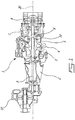
- FIG. 1 illustrates a gas turbine engine 1 of a type preferably provided for use in subsonic flight, generally comprising in serial flow communication an air intake duct 2 through which ambient air is propelled, a low pressure centrifugal compressor 3, diffuser ducts 4, an inter-compressor case 5 and a high pressure centrifugal compressor 6 for pressurizing the air, a combustor 7 in which the compressed air is mixed with fuel and ignited for generating an annular stream of hot combustion gases, and a turbine section 8 for extracting energy from the combustion gases, i.e.: high pressure turbines to drive the compressors 3, 6 and low pressure turbines to drive the engine shaft 9 and gear reducer 10.
- a gas turbine engine 1 of a type preferably provided for use in subsonic flight, generally comprising in serial flow communication an air intake duct 2 through which ambient air is propelled, a low pressure centrifugal compressor 3, diffuser ducts 4, an inter-compressor case 5 and a high pressure centrifugal compressor 6 for pressurizing the air,
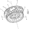
- the present description relates to an inter-compressor case (ICC) 5 of the type shown in the example illustrated in Figure 2 .
- the inter-compressor case 5 has an inner surface 12 radially spaced apart about a longitudinal axis 20 of the engine ( Fig.1 ).
- Radial inlets 13 are arranged in a circumferentially spaced apart array on the outer casing 11. As shown in Figure 1 , the radial inlets 13 each connect to separate diffuser ducts 4 that convey compressed air from the outlet of the low pressure centrifugal compressor 3.
- annular outlet 14 conveys air to the inlet of the high pressure centrifugal compressor 6.
- the annular outlet 14 is defined by an axially extending downstream portion of the outer shroud surface 25 and an axially extending downstream portion of the inner casing 12 (i.e.: the hub).
- a plurality of struts 15 have an exposed gas path surface extending between the outer shroud surface 25 and the inner surface 12.
- the struts 15 provide structural support between the central shaft bearing cavities and outer engine structures.
- the struts 15 are usually hollow or provide conduits through which oil or air can be conveyed to the inner engine components such as the shaft bearing cavity.
- a plurality of wedge shaped flow separators 16, 17 extend from the plurality of radial inlets 13.
- Each of the plurality of flow separators 16, 17 has a trailing edge 18, 19 disposed upstream of the annular outlet 14.
- the plurality of flow separators 16, 17 are adapted to receive discrete radial flows of gas from each of the radial inlets 13 and to merge the discrete radial flows of gas into a single annular flow of gas directed to the annular outlet 14.
- Figure 3 shows a prior art ICC where all flow separators 16 are the same length extending radially inwardly.
- a restriction in the gas flow channel occurs. The restriction in cross-sectional area of the gas flow channels creates a flow disruption or disturbance when a more uniform consistent flow is desirable.
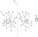
- FIGS. 4 and 5 show a modification which reduces flow disruption.
- the radial array of flow separators 16, 17 include a plurality of full length flow separators 16 and a plurality of truncated flow separators 17.
- the truncated flow separators 17 are located laterally adjacent to each of the struts 15 on either side.
- the truncated flow separators 17 have a truncated trailing edge 19 disposed upstream from the trailing edges 18 of the plurality of full length flow separators 16.
- the truncated trailing edge 19 enlarges the cross-sectional area (circled) adjacent to the strut 15 and thereby reduces the gas flow restriction.
- the full length flow separators 16 define a plurality of full length gas flow channels 21 having a full channel cross-sectional area defined between the trailing edges 18 of a pair of adjacent full length flow separators 16.
- the truncated flow separators 17 and struts 15 define a plurality of truncated gas flow channels 22 between the truncated trailing edge 19 and the gas path surface of the strut 15.
- the plurality of truncated gas flow channels 22 have a truncated channel cross-sectional area (circled area in Fig. 4 ) not less than the full channel cross-sectional area of the full gas flow channels 21. Ideally the truncated channel cross-sectional area is substantially equal to the full channel cross-sectional area.
- the truncated gas flow channel 21 is shown guiding gas flow from the radial inlet 13 to the annular outlet 14 as indicated with arrows.
- the truncated gas flow separator 17 has a truncated trailing edge 19 that is inclined relative to a gas flow direction past the truncated trailing edge 19.
- a radially outward portion 23 of the truncated trailing edge 19 extends in an upstream direction beyond a radially inward portion 24 of the truncated trailing edge 19.
- the radially outward portion 23 of the truncated trailing edge can also extend in a downstream direction beyond the radially inward portion 24 of the truncated trailing edge 19.
- the truncated trailing edge 19 need not be perpendicular to the gas flow direction but may be inclined or cambered to achieve various modifications to the gas flow pattern.
- Trimming the truncated trailing edge 19 and providing different profiles to the truncated trailing edge 19 can result in more uniform gas flow or other benefits.
Landscapes
- Engineering & Computer Science (AREA)
- Mechanical Engineering (AREA)
- General Engineering & Computer Science (AREA)
- Chemical & Material Sciences (AREA)
- Combustion & Propulsion (AREA)
- Physics & Mathematics (AREA)
- Fluid Mechanics (AREA)
- Structures Of Non-Positive Displacement Pumps (AREA)
Claims (12)
- Carter inter-compresseurs (5) pour un moteur à turbine à gaz (1), le carter inter-compresseurs (5) comprenant :un boîtier externe (11) et un boîtier interne (12) espacés radialement par rapport à un axe longitudinal (20) ; etun trajet de gaz s'étendant depuis une pluralité d'entrées radiales (13) agencées dans un réseau espacé circonférentiellement autour du boîtier externe (11) jusqu'à une sortie annulaire (14) définie par une partie aval s'étendant axialement du boîtier externe (11) et une partie aval s'étendant axialement du boîtier interne (12), caractérisé en ce que le carter inter-compresseurs (5) comprend en outre :une pluralité d'entretoises (15) ayant une surface de trajet de gaz s'étendant à travers le trajet de gaz entre le boîtier externe (11) et le boîtier interne (12) ; etune pluralité de séparateurs de flux (16, 17) s'étendant depuis les entrées radiales adjacentes (13), les séparateurs de flux (16, 17) ayant des bords de fuite (18, 19) disposés en amont de la sortie annulaire (14), la pluralité de séparateurs de flux (16, 17) comportant une pluralité de séparateurs de flux pleine longueur (16) et une pluralité de séparateurs de flux tronqués (17), les séparateurs de flux (16, 17) étant disposés adjacents aux entretoises (15), les séparateurs de flux tronqués (17) ayant un bord de fuite tronqué (19) se terminant en amont par rapport aux bords de fuite (18) des séparateurs de flux pleine longueur (16).
- Carter inter-compresseurs selon la revendication 1, dans lequel :la pluralité de séparateurs de flux pleine longueur (16) définissent une pluralité de canaux de flux de gaz pleine longueur (21) ayant une section transversale de canal complet définie entre les bords de fuite (18) d'une paire de séparateurs de flux pleine longueur adjacents (16) ; etles séparateurs de flux tronqués (17) et les entretoises (15) définissent une pluralité de canaux de flux de gaz tronqués (22) entre le bord de fuite tronqué (19) et la surface de trajet de gaz de l'entretoise (15), la pluralité de canaux de flux de gaz tronqués (22) ayant une section transversale de canal tronqué non inférieure à la section transversale de canal complet.
- Carter inter-compresseurs selon la revendication 2, dans lequel la section transversale de canal tronqué est sensiblement égale à la section transversale de canal complet.
- Carter inter-compresseurs selon une quelconque revendication précédente, dans lequel le bord de fuite tronqué (19) est incliné par rapport à une direction de flux de gaz au-delà du bord de fuite tronqué (19).
- Carter inter-compresseurs selon la revendication 4, dans lequel une partie radialement vers l'extérieur (23) du bord de fuite tronqué (19) s'étend au-delà d'une partie radialement vers l'intérieur (24) du bord de fuite tronqué (19) dans une direction amont.
- Carter inter-compresseurs selon la revendication 4, dans lequel une partie radialement vers l'extérieur (23) du bord de fuite tronqué (19) s'étend au-delà d'une partie radialement vers l'intérieur (24) du bord de fuite tronqué (19) dans une direction aval.
- Procédé de réduction de distorsion de flux dans un carter inter-compresseurs (5) pour un moteur à turbine à gaz (1), le carter inter-compresseurs (5) comprenant :un boîtier externe (11) et un boîtier interne (12) espacés radialement par rapport à un axe longitudinal (20) ; etun trajet de gaz s'étendant depuis une pluralité d'entrées radiales (13) agencées dans un réseau espacé circonférentiellement autour du boîtier externe (11) jusqu'à une sortie annulaire (14) définie par une partie aval s'étendant axialement du boîtier externe (11) et une partie aval s'étendant axialement du boîtier interne (12),caractérisé en ce que le carter inter-compresseurs (5) comprend en outre :une pluralité d'entretoises (15) ayant une surface de trajet de gaz s'étendant à travers le trajet de gaz entre le boîtier externe (11) et le boîtier interne (12) ; etune pluralité de séparateurs de flux (16, 17) s'étendant depuis les entrées radiales adjacentes (13), les séparateurs de flux (16, 17) ayant des bords de fuite (18, 19) disposés en amont de la sortie annulaire (14) ;le procédé comprenant :
le fait de faire en sorte que la pluralité de séparateurs de flux (16, 17) comportent une pluralité de séparateurs de flux pleine longueur (16) et une pluralité de séparateurs de flux tronqués (17), les séparateurs de flux (16, 17) étant disposés adjacents aux entretoises (15), les séparateurs de flux tronqués (17) ayant un bord de fuite tronqué (19) se terminant en amont par rapport aux bords de fuite (18) des séparateurs de flux pleine longueur (16). - Procédé selon la revendication 6, dans lequel :la pluralité de séparateurs de flux pleine longueur (16) définissent une pluralité de canaux de flux de gaz pleine longueur (21) ayant une section transversale de canal complet définie entre les bords de fuite (18) d'une paire de séparateurs de flux pleine longueur adjacents (16) ; etles séparateurs de flux tronqués (17) et les entretoises (15) définissent une pluralité de canaux de flux de gaz tronqués (22) entre le bord de fuite tronqué (19) et la surface de trajet de gaz de l'entretoise (15), la pluralité de canaux de flux de gaz tronqués (22) ayant une section transversale de canal tronqué non inférieure à la section transversale de canal complet.
- Procédé selon la revendication 8, dans lequel la section transversale de canal tronqué est sensiblement égale à la section transversale de canal complet.
- Procédé selon l'une quelconque des revendications 7 à 9, dans lequel le bord de fuite tronqué (19) est incliné par rapport à une direction de flux de gaz au-delà du bord de fuite tronqué (19) .
- Procédé selon la revendication 10, dans lequel une partie radialement vers l'extérieur (23) du bord de fuite tronqué (19) s'étend au-delà d'une partie radialement vers l'intérieur (24) du bord de fuite tronqué (19) dans une direction amont.
- Procédé selon la revendication 10, dans lequel une partie radialement vers l'extérieur (23) du bord de fuite tronqué (19) s'étend au-delà d'une partie radialement vers l'intérieur (24) du bord de fuite tronqué (19) dans une direction aval.
Priority Applications (1)
| Application Number | Priority Date | Filing Date | Title |
|---|---|---|---|
| PL19211952T PL3660272T3 (pl) | 2018-11-27 | 2019-11-27 | Profilowanie rozdzielacza przepływu między sprężarkami |
Applications Claiming Priority (1)
| Application Number | Priority Date | Filing Date | Title |
|---|---|---|---|
| US16/201,255 US10781705B2 (en) | 2018-11-27 | 2018-11-27 | Inter-compressor flow divider profiling |
Publications (2)
| Publication Number | Publication Date |
|---|---|
| EP3660272A1 EP3660272A1 (fr) | 2020-06-03 |
| EP3660272B1 true EP3660272B1 (fr) | 2021-07-14 |
Family
ID=68731741
Family Applications (1)
| Application Number | Title | Priority Date | Filing Date |
|---|---|---|---|
| EP19211952.7A Active EP3660272B1 (fr) | 2018-11-27 | 2019-11-27 | Profilé de séparateur de flux inter-compresseurs |
Country Status (4)
| Country | Link |
|---|---|
| US (1) | US10781705B2 (fr) |
| EP (1) | EP3660272B1 (fr) |
| CA (1) | CA3059950A1 (fr) |
| PL (1) | PL3660272T3 (fr) |
Families Citing this family (2)
| Publication number | Priority date | Publication date | Assignee | Title |
|---|---|---|---|---|
| CN112922861B (zh) * | 2021-01-29 | 2021-12-28 | 西安交通大学 | 一种紧凑式低转速离心压气机 |
| US11885263B2 (en) | 2021-06-17 | 2024-01-30 | Pratt & Whitney Canada Corp. | Secondary air supply system with feed pipe(s) having sonic orifice(s) |
Family Cites Families (39)
| Publication number | Priority date | Publication date | Assignee | Title |
|---|---|---|---|---|
| CA1153212A (fr) | 1980-07-02 | 1983-09-06 | Michael D. Stoten | Turbomoteur a gaz |
| US4645419A (en) * | 1984-09-10 | 1987-02-24 | Ebara Corporation | Centrifugal compressor |
| US4989406A (en) | 1988-12-29 | 1991-02-05 | General Electric Company | Turbine engine assembly with aft mounted outlet guide vanes |
| GB9805030D0 (en) | 1998-03-11 | 1998-05-06 | Rolls Royce Plc | A stator vane assembly for a turbomachine |
| US6363706B1 (en) * | 1998-12-24 | 2002-04-02 | Alliedsignal | Apparatus and method to increase turbine power |
| US6280139B1 (en) | 1999-10-18 | 2001-08-28 | Pratt & Whitney Canada Corp. | Radial split diffuser |
| JP2002005089A (ja) * | 2000-06-20 | 2002-01-09 | Mitsubishi Heavy Ind Ltd | ターボ形圧縮機及びそれを備えた冷凍装置 |
| US6345503B1 (en) * | 2000-09-21 | 2002-02-12 | Caterpillar Inc. | Multi-stage compressor in a turbocharger and method of configuring same |
| US6589015B1 (en) | 2002-05-08 | 2003-07-08 | Pratt & Whitney Canada Corp. | Discrete passage diffuser |
| US8757965B2 (en) | 2004-06-01 | 2014-06-24 | Volvo Aero Corporation | Gas turbine compression system and compressor structure |
| TWI266831B (en) * | 2005-12-15 | 2006-11-21 | Ind Tech Res Inst | Jet channel structure of refrigerant compressor |
| US7717672B2 (en) * | 2006-08-29 | 2010-05-18 | Honeywell International Inc. | Radial vaned diffusion system with integral service routings |
| US20080072566A1 (en) | 2006-09-27 | 2008-03-27 | Pratt & Whitney Canada Corp. | Bleed holes oriented with gaspath and flared for noise reduction |
| US8182204B2 (en) | 2009-04-24 | 2012-05-22 | Pratt & Whitney Canada Corp. | Deflector for a gas turbine strut and vane assembly |
| US8157517B2 (en) * | 2009-04-27 | 2012-04-17 | Elliott Company | Boltless multi-part diaphragm for use with a centrifugal compressor |
| DE102009019061A1 (de) * | 2009-04-27 | 2010-10-28 | Man Diesel & Turbo Se | Mehrstufiger Radialverdichter |
| DE102010002394A1 (de) | 2010-02-26 | 2011-09-01 | Rolls-Royce Deutschland Ltd & Co Kg | Nebenstromkanal eines Turbofantriebwerks |
| WO2012125085A1 (fr) | 2011-03-14 | 2012-09-20 | Volvo Aero Corporation | Aube guide composite |
| US9121284B2 (en) | 2012-01-27 | 2015-09-01 | United Technologies Corporation | Modal tuning for vanes |
| US9068460B2 (en) | 2012-03-30 | 2015-06-30 | United Technologies Corporation | Integrated inlet vane and strut |
| US10087950B2 (en) * | 2013-01-28 | 2018-10-02 | Mitsubishi Heavy Industries Compressor Corporation | Centrifugal rotation machine |
| US10221707B2 (en) | 2013-03-07 | 2019-03-05 | Pratt & Whitney Canada Corp. | Integrated strut-vane |
| FR3007458B1 (fr) | 2013-06-21 | 2017-11-10 | Snecma | Carter intermediaire ameliore de turbomachine et ensemble d'entrainement de boitier d'accessoire |
| US10094223B2 (en) | 2014-03-13 | 2018-10-09 | Pratt & Whitney Canada Corp. | Integrated strut and IGV configuration |
| US10060263B2 (en) | 2014-09-15 | 2018-08-28 | United Technologies Corporation | Incidence-tolerant, high-turning fan exit stator |
| GB201512838D0 (en) | 2015-07-21 | 2015-09-02 | Rolls Royce Plc | A turbine stator vane assembly for a turbomachine |
| US9909434B2 (en) | 2015-07-24 | 2018-03-06 | Pratt & Whitney Canada Corp. | Integrated strut-vane nozzle (ISV) with uneven vane axial chords |
| EP3241989A1 (fr) | 2016-05-04 | 2017-11-08 | Siemens Aktiengesellschaft | Section de turbine à gaz présentant une meilleure conception d'entretoise |
| EP3364039A1 (fr) * | 2017-02-21 | 2018-08-22 | Siemens Aktiengesellschaft | Étage de retour |
| JP6763803B2 (ja) * | 2017-02-22 | 2020-09-30 | 三菱重工コンプレッサ株式会社 | 遠心回転機械 |
| GB201703423D0 (en) | 2017-03-03 | 2017-04-19 | Rolls Royce Plc | Gas turbine engine vanes |
| GB201703422D0 (en) | 2017-03-03 | 2017-04-19 | Rolls Royce Plc | Gas turbine engine vanes |
| US20180306041A1 (en) | 2017-04-25 | 2018-10-25 | General Electric Company | Multiple turbine vane frame |
| US10760587B2 (en) * | 2017-06-06 | 2020-09-01 | Elliott Company | Extended sculpted twisted return channel vane arrangement |
| DE102017212311A1 (de) | 2017-07-19 | 2019-01-24 | MTU Aero Engines AG | Umströmungsanordung zum Anordnen im Heißgaskanal einer Strömungsmaschine |
| US20190107046A1 (en) | 2017-10-05 | 2019-04-11 | General Electric Company | Turbine engine with struts |
| GB2568109B (en) | 2017-11-07 | 2021-06-09 | Gkn Aerospace Sweden Ab | Splitter vane |
| JP6935312B2 (ja) | 2017-11-29 | 2021-09-15 | 三菱重工コンプレッサ株式会社 | 多段遠心圧縮機 |
| US20190178259A1 (en) * | 2017-12-12 | 2019-06-13 | Honeywell International Inc. | Variable return channel vanes to extend the operating flow range of a vapor cycle centrifugal compressor |
-
2018
- 2018-11-27 US US16/201,255 patent/US10781705B2/en active Active
-
2019
- 2019-10-24 CA CA3059950A patent/CA3059950A1/fr active Pending
- 2019-11-27 PL PL19211952T patent/PL3660272T3/pl unknown
- 2019-11-27 EP EP19211952.7A patent/EP3660272B1/fr active Active
Also Published As
| Publication number | Publication date |
|---|---|
| US10781705B2 (en) | 2020-09-22 |
| US20200165924A1 (en) | 2020-05-28 |
| EP3660272A1 (fr) | 2020-06-03 |
| PL3660272T3 (pl) | 2021-12-27 |
| CA3059950A1 (fr) | 2020-05-27 |
Similar Documents
| Publication | Publication Date | Title |
|---|---|---|
| EP0942150B1 (fr) | Configuration des aubes statoriques d'une turbomachine | |
| EP2775098B1 (fr) | Entretoise support intégrée à une aube directrice | |
| US8528344B2 (en) | Bleed structure for a bleed passage in a gas turbine engine | |
| JP5507828B2 (ja) | 非対称流れ抽出システム | |
| US8182204B2 (en) | Deflector for a gas turbine strut and vane assembly | |
| EP2860354B1 (fr) | Agencement integré d'aubes directrices de turbine avec entretoise de support | |
| US9909434B2 (en) | Integrated strut-vane nozzle (ISV) with uneven vane axial chords | |
| EP2775119B1 (fr) | Orifices de prélèvement inversés dans un carénage de compresseur | |
| US8757965B2 (en) | Gas turbine compression system and compressor structure | |
| CN110397504B (zh) | 燃烧腔室布置和包括燃烧腔室布置的气体涡轮引擎 | |
| US20170022835A1 (en) | Turbine stator vane assembly for a turbomachine | |
| US9784133B2 (en) | Turbine frame and airfoil for turbine frame | |
| JP5124276B2 (ja) | ガスタービン中間構造および該中間構造を含むガスタービンエンジン | |
| KR20100080427A (ko) | 터빈 엔진용 인듀서와 관련된 방법, 시스템 및/또는 장치 | |
| EP2568120B1 (fr) | Stator de moteur de turbine et procédé d'assemblage de celui-ci | |
| US11286951B2 (en) | Diffuser pipe with exit scallops | |
| US10781705B2 (en) | Inter-compressor flow divider profiling | |
| US20200024986A1 (en) | Gas turbine engine component | |
| EP1856398B1 (fr) | Structure de ventilation pour un passage de ventilation dans un moteur a turbine a gaz | |
| JP4918034B2 (ja) | ガスタービン圧縮システム及びコンプレッサ構造部 | |
| US8784050B2 (en) | Aggregate vane assembly | |
| US11401835B2 (en) | Turbine center frame | |
| EP4144958B1 (fr) | Machine à fluide pour un moteur d'aéronef et moteur d'aéronef | |
| EP3118416B1 (fr) | Moteur à turbine à gaz |
Legal Events
| Date | Code | Title | Description |
|---|---|---|---|
| PUAI | Public reference made under article 153(3) epc to a published international application that has entered the european phase |
Free format text: ORIGINAL CODE: 0009012 |
|
| STAA | Information on the status of an ep patent application or granted ep patent |
Free format text: STATUS: THE APPLICATION HAS BEEN PUBLISHED |
|
| AK | Designated contracting states |
Kind code of ref document: A1 Designated state(s): AL AT BE BG CH CY CZ DE DK EE ES FI FR GB GR HR HU IE IS IT LI LT LU LV MC MK MT NL NO PL PT RO RS SE SI SK SM TR |
|
| AX | Request for extension of the european patent |
Extension state: BA ME |
|
| STAA | Information on the status of an ep patent application or granted ep patent |
Free format text: STATUS: REQUEST FOR EXAMINATION WAS MADE |
|
| REG | Reference to a national code |
Ref country code: DE Ref legal event code: R079 Ref document number: 602019006115 Country of ref document: DE Free format text: PREVIOUS MAIN CLASS: F01D0009060000 Ipc: F04D0017120000 |
|
| 17P | Request for examination filed |
Effective date: 20201203 |
|
| RBV | Designated contracting states (corrected) |
Designated state(s): AL AT BE BG CH CY CZ DE DK EE ES FI FR GB GR HR HU IE IS IT LI LT LU LV MC MK MT NL NO PL PT RO RS SE SI SK SM TR |
|
| RIC1 | Information provided on ipc code assigned before grant |
Ipc: F01D 25/24 20060101ALI20201218BHEP Ipc: F01D 25/16 20060101ALI20201218BHEP Ipc: F01D 9/04 20060101ALI20201218BHEP Ipc: F01D 9/06 20060101ALI20201218BHEP Ipc: F04D 17/12 20060101AFI20201218BHEP Ipc: F04D 29/44 20060101ALI20201218BHEP |
|
| GRAP | Despatch of communication of intention to grant a patent |
Free format text: ORIGINAL CODE: EPIDOSNIGR1 |
|
| STAA | Information on the status of an ep patent application or granted ep patent |
Free format text: STATUS: GRANT OF PATENT IS INTENDED |
|
| INTG | Intention to grant announced |
Effective date: 20210129 |
|
| GRAS | Grant fee paid |
Free format text: ORIGINAL CODE: EPIDOSNIGR3 |
|
| GRAA | (expected) grant |
Free format text: ORIGINAL CODE: 0009210 |
|
| STAA | Information on the status of an ep patent application or granted ep patent |
Free format text: STATUS: THE PATENT HAS BEEN GRANTED |
|
| AK | Designated contracting states |
Kind code of ref document: B1 Designated state(s): AL AT BE BG CH CY CZ DE DK EE ES FI FR GB GR HR HU IE IS IT LI LT LU LV MC MK MT NL NO PL PT RO RS SE SI SK SM TR |
|
| REG | Reference to a national code |
Ref country code: GB Ref legal event code: FG4D |
|
| REG | Reference to a national code |
Ref country code: DE Ref legal event code: R096 Ref document number: 602019006115 Country of ref document: DE |
|
| REG | Reference to a national code |
Ref country code: IE Ref legal event code: FG4D |
|
| REG | Reference to a national code |
Ref country code: AT Ref legal event code: REF Ref document number: 1410868 Country of ref document: AT Kind code of ref document: T Effective date: 20210815 |
|
| REG | Reference to a national code |
Ref country code: LT Ref legal event code: MG9D |
|
| REG | Reference to a national code |
Ref country code: NL Ref legal event code: MP Effective date: 20210714 |
|
| REG | Reference to a national code |
Ref country code: AT Ref legal event code: MK05 Ref document number: 1410868 Country of ref document: AT Kind code of ref document: T Effective date: 20210714 |
|
| PG25 | Lapsed in a contracting state [announced via postgrant information from national office to epo] |
Ref country code: RS Free format text: LAPSE BECAUSE OF FAILURE TO SUBMIT A TRANSLATION OF THE DESCRIPTION OR TO PAY THE FEE WITHIN THE PRESCRIBED TIME-LIMIT Effective date: 20210714 Ref country code: SE Free format text: LAPSE BECAUSE OF FAILURE TO SUBMIT A TRANSLATION OF THE DESCRIPTION OR TO PAY THE FEE WITHIN THE PRESCRIBED TIME-LIMIT Effective date: 20210714 Ref country code: ES Free format text: LAPSE BECAUSE OF FAILURE TO SUBMIT A TRANSLATION OF THE DESCRIPTION OR TO PAY THE FEE WITHIN THE PRESCRIBED TIME-LIMIT Effective date: 20210714 Ref country code: LT Free format text: LAPSE BECAUSE OF FAILURE TO SUBMIT A TRANSLATION OF THE DESCRIPTION OR TO PAY THE FEE WITHIN THE PRESCRIBED TIME-LIMIT Effective date: 20210714 Ref country code: BG Free format text: LAPSE BECAUSE OF FAILURE TO SUBMIT A TRANSLATION OF THE DESCRIPTION OR TO PAY THE FEE WITHIN THE PRESCRIBED TIME-LIMIT Effective date: 20211014 Ref country code: AT Free format text: LAPSE BECAUSE OF FAILURE TO SUBMIT A TRANSLATION OF THE DESCRIPTION OR TO PAY THE FEE WITHIN THE PRESCRIBED TIME-LIMIT Effective date: 20210714 Ref country code: HR Free format text: LAPSE BECAUSE OF FAILURE TO SUBMIT A TRANSLATION OF THE DESCRIPTION OR TO PAY THE FEE WITHIN THE PRESCRIBED TIME-LIMIT Effective date: 20210714 Ref country code: FI Free format text: LAPSE BECAUSE OF FAILURE TO SUBMIT A TRANSLATION OF THE DESCRIPTION OR TO PAY THE FEE WITHIN THE PRESCRIBED TIME-LIMIT Effective date: 20210714 Ref country code: NL Free format text: LAPSE BECAUSE OF FAILURE TO SUBMIT A TRANSLATION OF THE DESCRIPTION OR TO PAY THE FEE WITHIN THE PRESCRIBED TIME-LIMIT Effective date: 20210714 Ref country code: NO Free format text: LAPSE BECAUSE OF FAILURE TO SUBMIT A TRANSLATION OF THE DESCRIPTION OR TO PAY THE FEE WITHIN THE PRESCRIBED TIME-LIMIT Effective date: 20211014 Ref country code: PT Free format text: LAPSE BECAUSE OF FAILURE TO SUBMIT A TRANSLATION OF THE DESCRIPTION OR TO PAY THE FEE WITHIN THE PRESCRIBED TIME-LIMIT Effective date: 20211115 |
|
| PG25 | Lapsed in a contracting state [announced via postgrant information from national office to epo] |
Ref country code: LV Free format text: LAPSE BECAUSE OF FAILURE TO SUBMIT A TRANSLATION OF THE DESCRIPTION OR TO PAY THE FEE WITHIN THE PRESCRIBED TIME-LIMIT Effective date: 20210714 Ref country code: GR Free format text: LAPSE BECAUSE OF FAILURE TO SUBMIT A TRANSLATION OF THE DESCRIPTION OR TO PAY THE FEE WITHIN THE PRESCRIBED TIME-LIMIT Effective date: 20211015 |
|
| REG | Reference to a national code |
Ref country code: DE Ref legal event code: R097 Ref document number: 602019006115 Country of ref document: DE |
|
| PG25 | Lapsed in a contracting state [announced via postgrant information from national office to epo] |
Ref country code: DK Free format text: LAPSE BECAUSE OF FAILURE TO SUBMIT A TRANSLATION OF THE DESCRIPTION OR TO PAY THE FEE WITHIN THE PRESCRIBED TIME-LIMIT Effective date: 20210714 |
|
| PLBE | No opposition filed within time limit |
Free format text: ORIGINAL CODE: 0009261 |
|
| STAA | Information on the status of an ep patent application or granted ep patent |
Free format text: STATUS: NO OPPOSITION FILED WITHIN TIME LIMIT |
|
| PG25 | Lapsed in a contracting state [announced via postgrant information from national office to epo] |
Ref country code: SM Free format text: LAPSE BECAUSE OF FAILURE TO SUBMIT A TRANSLATION OF THE DESCRIPTION OR TO PAY THE FEE WITHIN THE PRESCRIBED TIME-LIMIT Effective date: 20210714 Ref country code: SK Free format text: LAPSE BECAUSE OF FAILURE TO SUBMIT A TRANSLATION OF THE DESCRIPTION OR TO PAY THE FEE WITHIN THE PRESCRIBED TIME-LIMIT Effective date: 20210714 Ref country code: RO Free format text: LAPSE BECAUSE OF FAILURE TO SUBMIT A TRANSLATION OF THE DESCRIPTION OR TO PAY THE FEE WITHIN THE PRESCRIBED TIME-LIMIT Effective date: 20210714 Ref country code: EE Free format text: LAPSE BECAUSE OF FAILURE TO SUBMIT A TRANSLATION OF THE DESCRIPTION OR TO PAY THE FEE WITHIN THE PRESCRIBED TIME-LIMIT Effective date: 20210714 Ref country code: AL Free format text: LAPSE BECAUSE OF FAILURE TO SUBMIT A TRANSLATION OF THE DESCRIPTION OR TO PAY THE FEE WITHIN THE PRESCRIBED TIME-LIMIT Effective date: 20210714 |
|
| 26N | No opposition filed |
Effective date: 20220419 |
|
| PG25 | Lapsed in a contracting state [announced via postgrant information from national office to epo] |
Ref country code: MC Free format text: LAPSE BECAUSE OF FAILURE TO SUBMIT A TRANSLATION OF THE DESCRIPTION OR TO PAY THE FEE WITHIN THE PRESCRIBED TIME-LIMIT Effective date: 20210714 |
|
| PG25 | Lapsed in a contracting state [announced via postgrant information from national office to epo] |
Ref country code: LU Free format text: LAPSE BECAUSE OF NON-PAYMENT OF DUE FEES Effective date: 20211127 Ref country code: IT Free format text: LAPSE BECAUSE OF FAILURE TO SUBMIT A TRANSLATION OF THE DESCRIPTION OR TO PAY THE FEE WITHIN THE PRESCRIBED TIME-LIMIT Effective date: 20210714 Ref country code: BE Free format text: LAPSE BECAUSE OF NON-PAYMENT OF DUE FEES Effective date: 20211130 |
|
| REG | Reference to a national code |
Ref country code: BE Ref legal event code: MM Effective date: 20211130 |
|
| PG25 | Lapsed in a contracting state [announced via postgrant information from national office to epo] |
Ref country code: IE Free format text: LAPSE BECAUSE OF NON-PAYMENT OF DUE FEES Effective date: 20211127 |
|
| PG25 | Lapsed in a contracting state [announced via postgrant information from national office to epo] |
Ref country code: CY Free format text: LAPSE BECAUSE OF FAILURE TO SUBMIT A TRANSLATION OF THE DESCRIPTION OR TO PAY THE FEE WITHIN THE PRESCRIBED TIME-LIMIT Effective date: 20210714 |
|
| REG | Reference to a national code |
Ref country code: CH Ref legal event code: PL |
|
| P01 | Opt-out of the competence of the unified patent court (upc) registered |
Effective date: 20230530 |
|
| PG25 | Lapsed in a contracting state [announced via postgrant information from national office to epo] |
Ref country code: LI Free format text: LAPSE BECAUSE OF NON-PAYMENT OF DUE FEES Effective date: 20221130 Ref country code: HU Free format text: LAPSE BECAUSE OF FAILURE TO SUBMIT A TRANSLATION OF THE DESCRIPTION OR TO PAY THE FEE WITHIN THE PRESCRIBED TIME-LIMIT; INVALID AB INITIO Effective date: 20191127 Ref country code: CH Free format text: LAPSE BECAUSE OF NON-PAYMENT OF DUE FEES Effective date: 20221130 |
|
| PG25 | Lapsed in a contracting state [announced via postgrant information from national office to epo] |
Ref country code: MK Free format text: LAPSE BECAUSE OF FAILURE TO SUBMIT A TRANSLATION OF THE DESCRIPTION OR TO PAY THE FEE WITHIN THE PRESCRIBED TIME-LIMIT Effective date: 20210714 |
|
| PG25 | Lapsed in a contracting state [announced via postgrant information from national office to epo] |
Ref country code: TR Free format text: LAPSE BECAUSE OF FAILURE TO SUBMIT A TRANSLATION OF THE DESCRIPTION OR TO PAY THE FEE WITHIN THE PRESCRIBED TIME-LIMIT Effective date: 20210714 |
|
| PG25 | Lapsed in a contracting state [announced via postgrant information from national office to epo] |
Ref country code: MT Free format text: LAPSE BECAUSE OF FAILURE TO SUBMIT A TRANSLATION OF THE DESCRIPTION OR TO PAY THE FEE WITHIN THE PRESCRIBED TIME-LIMIT Effective date: 20210714 |
|
| PGFP | Annual fee paid to national office [announced via postgrant information from national office to epo] |
Ref country code: DE Payment date: 20251022 Year of fee payment: 7 |
|
| PGFP | Annual fee paid to national office [announced via postgrant information from national office to epo] |
Ref country code: GB Payment date: 20251023 Year of fee payment: 7 |
|
| PGFP | Annual fee paid to national office [announced via postgrant information from national office to epo] |
Ref country code: FR Payment date: 20251022 Year of fee payment: 7 |
|
| PGFP | Annual fee paid to national office [announced via postgrant information from national office to epo] |
Ref country code: CZ Payment date: 20251104 Year of fee payment: 7 |
|
| PGFP | Annual fee paid to national office [announced via postgrant information from national office to epo] |
Ref country code: PL Payment date: 20251022 Year of fee payment: 7 |