EP3660338A1 - Dispositif de compensation de tolérance doté d'un moyen de couplage - Google Patents
Dispositif de compensation de tolérance doté d'un moyen de couplage Download PDFInfo
- Publication number
- EP3660338A1 EP3660338A1 EP19212020.2A EP19212020A EP3660338A1 EP 3660338 A1 EP3660338 A1 EP 3660338A1 EP 19212020 A EP19212020 A EP 19212020A EP 3660338 A1 EP3660338 A1 EP 3660338A1
- Authority
- EP
- European Patent Office
- Prior art keywords
- coupling means
- groove
- tolerance compensation
- compensation device
- section
- Prior art date
- Legal status (The legal status is an assumption and is not a legal conclusion. Google has not performed a legal analysis and makes no representation as to the accuracy of the status listed.)
- Granted
Links
Images





Classifications
-
- F—MECHANICAL ENGINEERING; LIGHTING; HEATING; WEAPONS; BLASTING
- F16—ENGINEERING ELEMENTS AND UNITS; GENERAL MEASURES FOR PRODUCING AND MAINTAINING EFFECTIVE FUNCTIONING OF MACHINES OR INSTALLATIONS; THERMAL INSULATION IN GENERAL
- F16B—DEVICES FOR FASTENING OR SECURING CONSTRUCTIONAL ELEMENTS OR MACHINE PARTS TOGETHER, e.g. NAILS, BOLTS, CIRCLIPS, CLAMPS, CLIPS OR WEDGES; JOINTS OR JOINTING
- F16B37/00—Nuts or like thread-engaging members
- F16B37/08—Quickly-detachable or mountable nuts, e.g. consisting of two or more parts; Nuts movable along the bolt after tilting the nut
-
- F—MECHANICAL ENGINEERING; LIGHTING; HEATING; WEAPONS; BLASTING
- F16—ENGINEERING ELEMENTS AND UNITS; GENERAL MEASURES FOR PRODUCING AND MAINTAINING EFFECTIVE FUNCTIONING OF MACHINES OR INSTALLATIONS; THERMAL INSULATION IN GENERAL
- F16B—DEVICES FOR FASTENING OR SECURING CONSTRUCTIONAL ELEMENTS OR MACHINE PARTS TOGETHER, e.g. NAILS, BOLTS, CIRCLIPS, CLAMPS, CLIPS OR WEDGES; JOINTS OR JOINTING
- F16B5/00—Joining sheets or plates, e.g. panels, to one another or to strips or bars parallel to them
- F16B5/02—Joining sheets or plates, e.g. panels, to one another or to strips or bars parallel to them by means of fastening members using screw-thread
- F16B5/0241—Joining sheets or plates, e.g. panels, to one another or to strips or bars parallel to them by means of fastening members using screw-thread with the possibility for the connection to absorb deformation, e.g. thermal or vibrational
-
- F—MECHANICAL ENGINEERING; LIGHTING; HEATING; WEAPONS; BLASTING
- F16—ENGINEERING ELEMENTS AND UNITS; GENERAL MEASURES FOR PRODUCING AND MAINTAINING EFFECTIVE FUNCTIONING OF MACHINES OR INSTALLATIONS; THERMAL INSULATION IN GENERAL
- F16B—DEVICES FOR FASTENING OR SECURING CONSTRUCTIONAL ELEMENTS OR MACHINE PARTS TOGETHER, e.g. NAILS, BOLTS, CIRCLIPS, CLAMPS, CLIPS OR WEDGES; JOINTS OR JOINTING
- F16B5/00—Joining sheets or plates, e.g. panels, to one another or to strips or bars parallel to them
- F16B5/02—Joining sheets or plates, e.g. panels, to one another or to strips or bars parallel to them by means of fastening members using screw-thread
- F16B5/0216—Joining sheets or plates, e.g. panels, to one another or to strips or bars parallel to them by means of fastening members using screw-thread the position of the plates to be connected being adjustable
- F16B5/0233—Joining sheets or plates, e.g. panels, to one another or to strips or bars parallel to them by means of fastening members using screw-thread the position of the plates to be connected being adjustable allowing for adjustment perpendicular to the plane of the plates
-
- F—MECHANICAL ENGINEERING; LIGHTING; HEATING; WEAPONS; BLASTING
- F16—ENGINEERING ELEMENTS AND UNITS; GENERAL MEASURES FOR PRODUCING AND MAINTAINING EFFECTIVE FUNCTIONING OF MACHINES OR INSTALLATIONS; THERMAL INSULATION IN GENERAL
- F16B—DEVICES FOR FASTENING OR SECURING CONSTRUCTIONAL ELEMENTS OR MACHINE PARTS TOGETHER, e.g. NAILS, BOLTS, CIRCLIPS, CLAMPS, CLIPS OR WEDGES; JOINTS OR JOINTING
- F16B27/00—Bolts, screws, or nuts formed in integral series but easily separable, particularly for use in automatic machines
-
- F—MECHANICAL ENGINEERING; LIGHTING; HEATING; WEAPONS; BLASTING
- F16—ENGINEERING ELEMENTS AND UNITS; GENERAL MEASURES FOR PRODUCING AND MAINTAINING EFFECTIVE FUNCTIONING OF MACHINES OR INSTALLATIONS; THERMAL INSULATION IN GENERAL
- F16B—DEVICES FOR FASTENING OR SECURING CONSTRUCTIONAL ELEMENTS OR MACHINE PARTS TOGETHER, e.g. NAILS, BOLTS, CIRCLIPS, CLAMPS, CLIPS OR WEDGES; JOINTS OR JOINTING
- F16B43/00—Washers or equivalent devices; Other devices for supporting bolt-heads or nuts
-
- F—MECHANICAL ENGINEERING; LIGHTING; HEATING; WEAPONS; BLASTING
- F16—ENGINEERING ELEMENTS AND UNITS; GENERAL MEASURES FOR PRODUCING AND MAINTAINING EFFECTIVE FUNCTIONING OF MACHINES OR INSTALLATIONS; THERMAL INSULATION IN GENERAL
- F16B—DEVICES FOR FASTENING OR SECURING CONSTRUCTIONAL ELEMENTS OR MACHINE PARTS TOGETHER, e.g. NAILS, BOLTS, CIRCLIPS, CLAMPS, CLIPS OR WEDGES; JOINTS OR JOINTING
- F16B5/00—Joining sheets or plates, e.g. panels, to one another or to strips or bars parallel to them
- F16B5/06—Joining sheets or plates, e.g. panels, to one another or to strips or bars parallel to them by means of clamps or clips
- F16B5/0607—Joining sheets or plates, e.g. panels, to one another or to strips or bars parallel to them by means of clamps or clips joining sheets or plates to each other
- F16B5/0621—Joining sheets or plates, e.g. panels, to one another or to strips or bars parallel to them by means of clamps or clips joining sheets or plates to each other in parallel relationship
- F16B5/0628—Joining sheets or plates, e.g. panels, to one another or to strips or bars parallel to them by means of clamps or clips joining sheets or plates to each other in parallel relationship allowing for adjustment parallel or perpendicular to the plane of the sheets or plates
-
- F—MECHANICAL ENGINEERING; LIGHTING; HEATING; WEAPONS; BLASTING
- F16—ENGINEERING ELEMENTS AND UNITS; GENERAL MEASURES FOR PRODUCING AND MAINTAINING EFFECTIVE FUNCTIONING OF MACHINES OR INSTALLATIONS; THERMAL INSULATION IN GENERAL
- F16B—DEVICES FOR FASTENING OR SECURING CONSTRUCTIONAL ELEMENTS OR MACHINE PARTS TOGETHER, e.g. NAILS, BOLTS, CIRCLIPS, CLAMPS, CLIPS OR WEDGES; JOINTS OR JOINTING
- F16B5/00—Joining sheets or plates, e.g. panels, to one another or to strips or bars parallel to them
- F16B5/06—Joining sheets or plates, e.g. panels, to one another or to strips or bars parallel to them by means of clamps or clips
- F16B5/0607—Joining sheets or plates, e.g. panels, to one another or to strips or bars parallel to them by means of clamps or clips joining sheets or plates to each other
- F16B5/0621—Joining sheets or plates, e.g. panels, to one another or to strips or bars parallel to them by means of clamps or clips joining sheets or plates to each other in parallel relationship
- F16B5/0635—Joining sheets or plates, e.g. panels, to one another or to strips or bars parallel to them by means of clamps or clips joining sheets or plates to each other in parallel relationship fastened over the edges of the sheets or plates
Definitions
- the present invention relates to a device for compensating for tolerances between two components to be connected by means of a connecting screw, comprising a basic element and a compensating element that can be moved out of the basic element, the basic element and the compensating element forming a passage for the connecting screw that defines an axial direction.
- Such a device which is also called tolerance compensation device, is known in principle and is used, for example, in automobile construction to tolerances in the distance between a first component, e.g. a support structure, body or the like, and a second component to be mounted thereon, e.g. a roof rail, instrument panel, door, hood, a seat, trunk lid or the like to compensate in the axial direction.
- the device can optionally be preassembled on the first component or on the second component.
- the device is attached to the first component, for example, via the base element.
- the compensating element is then moved upward in the direction of the second component from the base element until the end face of the compensating element comes into contact with the second component.
- the components can now be clamped together by means of the connecting screw extending through the components and the device.
- a movement of the compensating element out of the basic element can take place, for example, in that the compensating element out of the basic element is turned out.
- the base element and the compensation element can be in thread engagement, preferably in a left-hand thread engagement, so that the compensation element is automatically unscrewed from the base element when the connecting screw is screwed into an assigned nut element.
- a torque transmission means for example in the form of a spring element, is usually provided in the passage of the compensating element.
- the devices Before their intended use, the devices are kept in stock in a storage container in which they are usually present in any orientation. In order to be able to assemble a device in the desired manner, the device must be correctly aligned with respect to the first component. So far, this has been done by a manual setting process, in which a device is removed from the storage container and then manually attached to the first component. Such a procedure is therefore time-consuming and ultimately also cost-intensive.
- the invention has for its object to provide a device for compensating tolerances, which is suitable for an automated setting process.
- the tolerance compensation device is characterized by a coupling means which is designed to couple the device to a carrier element and to guide the device along the carrier element
- the invention is based on the general idea of providing a tolerance compensation device with a coupling means which enables the tolerance compensation device to be coupled to a carrier element through which the tolerance compensation device can be supplied correctly aligned to a setting robot so that the robot attaches the tolerance compensation device to a first of the components to be connected in the desired manner.
- the setting process can be automated, which makes the setting process easier, more precise, reproducible and ultimately also more cost-effective than a manual setting process.
- Another advantage of the invention is that the devices are ordered using the coupling means, i.e. aligned, stored and managed in a magazine. Such storage can be advantageous even in a manual setting process, since the devices can be removed from the magazine in a correctly aligned manner.
- the coupling means is formed on the base element.
- the base element for fastening the device to the first component can have at least one fastening means, which can be designed, for example, in the form of a holding clip, latching section, clamping means or the like.
- the coupling means can also be formed on a holding element for holding the base element.
- the holding element can also have at least one fastening means of the type described above.
- the base element or the holding element can also be attached to the first component in a cohesive manner in addition or as an alternative to a non-positive and / or positive connection, e.g. by welding or gluing it to the first component.
- the device coupled to the carrier element experiences a particularly advantageous alignment for a subsequent setting process if the coupling means has a longitudinal extension which is aligned at least approximately parallel to the axial direction.
- the longitudinal extension of the coupling means can also be oriented transversely, in particular at right angles, to the axial direction.
- the coupling means comprises a groove defining at least one undercut.
- the coupling means can engage behind a complementary rib of the carrier element and the device can be guided in any spatial direction without the device undesirably becoming detached from the carrier element.
- the rib of the carrier element can be gripped behind particularly well if the groove is a T-groove, an L-groove, a round groove, a dovetail groove or the like.
- the groove advantageously has an expanding section on at least one of its longitudinal ends. The widening longitudinal end of the groove makes it easier to thread the device onto the carrier element.
- the longitudinal end of the groove is located on a longitudinal end of the coupling means that limits the coupling means in the direction of its longitudinal extent.
- the coupling means can also comprise an arm defining at least one undercut, which extends radially or tangentially from an outer wall of the base element or an outer wall of the holding element stretched out. It is understood that the support element in this case has a complementarily shaped groove which engages behind the undercut of the arm for coupling the device to the support element.
- the coupling means preferably has a tapered section on at least one of its longitudinal ends. The longitudinal end limits the coupling means in the direction of its longitudinal extent.
- a particularly good engagement between the device and the carrier element can be achieved in that the arm at its free end facing away from the outer wall of the base element or the outer wall of the holding element merges into at least one angled hook section, so that the coupling means as a whole, for example, a T-shaped or L -shaped cross-section.
- the arm At its free end facing away from the outer wall of the base element or the outer wall of the holding element, the arm can also have a differently shaped undercut end section instead of a hook section, for example in such a way that the coupling means has a round, in particular mushroom-like, a dovetail-like or comparable cross section.
- the coupling means has an arm with a hook portion or a differently undercut end portion, the coupling means forms in a certain way a sliding block which, when the device is coupled, can be guided in a groove of the carrier element.
- a guide element is preferably provided on the coupling means.
- a guide element is preferably provided on the coupling means.
- At least two guide elements are preferably provided on opposite longitudinal sides of the coupling means in order to facilitate correct alignment of the device in the setting robot.
- the guide element formed on the coupling means can also serve to align and / or guide the device on a carrier element.
- the guide element can, for example, be in the form of a prism-like or hipped roof-like projection on the coupling means. However, it is also conceivable that the guide element represents a notch on the coupling means.
- the invention also relates to a system comprising at least one device of the type described above and a carrier element for receiving and guiding the at least one device.
- the device is preferably movably guided by the coupling means relative to the carrier element, as a result of which the device can be fed to a setting robot in a simple manner.
- the support element is flexible, at least in sections.
- the carrier element can alternatively or additionally be rigid at least in sections.
- the carrier element is tubular, such that the carrier element surrounds the coupled device in the radial direction.
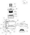
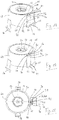
- the tolerance compensation device 14 comprises a base element 16 and a compensation element 18 which engages with it in left-handed thread.
- the base element 16 forms a left-handed internal thread 16a
- the compensation element 18 has a correspondingly designed external thread 18a.
- the thread axes of the internal thread 16a and the external thread 18a define an axial direction.
- the base element 16 and the compensating element 18 form a passage 20 extending in the axial direction for a connecting screw, not shown.
- a spring element 22 is inserted, which is provided for producing a frictional connection between the connecting screw extending through the passage 20 and the compensating element 18.
- the spring element 22 transmits a torque of the connecting screw to the compensating element and is therefore also referred to as a torque transmission means.
- the connecting screw is used for screwing two spaced apart components, of which in Fig. 2 a first component 24 is shown.
- a nut element 26 for the connecting screw is attached to the first component 24 in a rotationally fixed manner.
- the nut element 26 is a press-in nut which is pressed into a correspondingly provided receiving bore 28 in the first component 24.
- press-in nut is also understood to mean set nuts, rivet nuts, flare nuts, (impact) nuts, etc.
- fasten the nut element 26 to the first component 24 in another way, for example by means of gluing or welding.
- the tolerance compensation device 14 further comprises a holding element 30 formed from a plastic material, in which the base element 16 is held in a rotationally fixed manner.
- the base element 16 is pressed into the holding element 30.
- the base element 16 is seated in a holding section 32 of the holding element 30, which extends essentially at right angles to the axial direction.
- the holding element 30 forms a latching section 34, which likewise extends essentially at right angles to the axial direction.
- the latching section 34 is axially spaced from the holding section 32, which is adapted to the thickness of the first component 24.
- the latching section 34 comprises two latching arms 36 spaced apart from one another and slightly curved toward one another, which define a receptacle for the nut element 26 between them.
- the locking arms 36 have a certain elasticity in this way that they can be spread against the restoring force when pushed onto the nut element 26 in the radial direction and spring back again in their rest position as soon as the nut element 26 is received in the receptacle ( Fig. 4 ).
- the latching arms 36 In order to prevent inadvertent detachment of the latching section 34 from the received nut element 26, the latching arms 36 have latching projections 38 facing one another in the region of their free ends. For stiffening of the latching arms 36, they are connected in the area of their base by a stiffening element 40 which partially projects beyond the nut element 26 received in the receptacle.
- the tolerance compensation device 14 is pushed laterally, that is to say in the radial direction, onto the first component 24 in such a way that the first component is received between the holding portion 32 and the locking portion 34 and the locking portion 34 locked with the nut member 26, as in 3 and 4 is shown.
- insertion bevels 41 are formed both in the region of the free ends of the latching arms 36 and in the corresponding region of the holding section 32.
- the tolerance compensation device 14 does not necessarily have to be seated on the component 24 in the preassembled state. Rather, a certain play of the tolerance compensation device 14 locked on the nut element 26 is desired at least in the radial direction, but possibly also in the axial direction, since this facilitates the subsequent screwing of the components, in particular the alignment of the tolerance compensation device 14 with the connecting screw.
- the connecting screw is inserted through a corresponding hole in the component (not shown) and (in Fig. 1 from above) through the passage 20 of the tolerance compensation device 14 and screwed into the nut element 26. Due to the opposite thread of the connecting screw and tolerance compensation device 14, the compensation element 18 is screwed out of the base element 16 by the frictional connection produced by the spring element 22 until the abutment of the second component (not shown) while the connecting screw is screwed into the nut element 26. From this point in time, the distance between the components is bridged by the extended tolerance compensation device 14 and the components can be clamped together by tightening the connecting screw.
- the holding section 32 and the latching section 34 are connected to one another by a connecting section 42 which extends in the axial direction and to a certain extent forms the backbone of the holding element 30.
- the connecting section 42 has a cuboid basic shape and forms a T-groove 44 on its rear side facing away from the latching arms 36.
- the connecting section 42 forms a coupling means 43, the functioning of which will be discussed in more detail below.
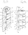
- the tolerance compensation device 14 can be pushed onto a correspondingly designed T-shaped carrier element 46 for transport and / or storage purposes, as shown in FIG Fig. 5 is illustrated using three tolerance compensation devices 14.
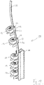
- the T-groove 44 enables the tolerance compensation device 14 to be threaded onto a flexible carrier element in the form of a carrier tape 48.
- Fig. 6 shows such a carrier tape 48 with a large number of tolerance compensation devices 14 threaded thereon.
- Such a configuration is suitable, for example, for the tolerance compensation devices 14 to be used by a setting robot for automated Pre-assemble the tolerance compensation devices 14 on one or more components 24.
- such a setting robot can be a gripping robot.
- the setting robot can also have a magnet for holding the tolerance compensation devices 14.
- an insert 50 made of a magnetizable, in particular ferromagnetic, material, for example a steel sheet, is embedded in the holding element 30, in the present exemplary embodiment in the area between the T-groove 44 and the stiffening element 40 magnetizable, in particular ferromagnetic, element can be provided on the coupling means 43 and preferably embedded in the coupling means 43 (not shown in the figures).
- two axially spaced prismatic or hipped roof-like guide elements 52 are also provided, which serve to additionally guide the tolerance compensation device 14 in a carrier element in the form of a magazine 54 ( Fig. 8 ).
- Fig. 7 shows a tolerance compensation device 14 according to a second embodiment, which ultimately only differs from the first embodiment described above in that the holding element 30 does not have a T-groove 44, but instead the insert 50 made of ferromagnetic material into the rear side of the connecting section facing away from the latching arms 36 42 is embedded.
- the guide elements 52 serve to guide the tolerance compensation device 14 in the magazine 54.
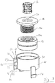
- FIG. 9 to 15 show a tolerance compensation device 14 according to a third embodiment, which is in the design of the holding element 30 and of the coupling means 43 differs from the tolerance compensation device 14 according to the first embodiment.
- the holding element 30 according to the tolerance compensation device 14 according to the third embodiment is designed essentially in the form of a ring and has two clip arms 56 projecting from the holding element 30 in the axial direction. The clip arms 56 are used to fasten the tolerance compensation device 14 to an appropriately designed first component.
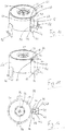
- a tolerance compensation device 14 according to a fourth embodiment which differs only in the design of the holding element 30 and the coupling means 43 from the tolerance compensation device 14 according to the third embodiment.
- a holding clip 57 is attached to the holding element 30.
- a nut element for the connecting screw which is not recognizable in the figures, is mounted in the holding clip 57.
- the holding clamp 57 is used to clamp the tolerance compensation device 14 to a first component.
- the coupling means 43 is designed to couple the tolerance compensation device 14 to a carrier element 46, 48, 54 in such a way that the tolerance compensation device 14 can be moved along the carrier element 46, 48, 54.
- the support element can be a rigid support element 46 ( 5A and 5B ) or a flexible support element 48 ( 6A to 6D ) act.
- a combination of rigid and flexible support elements 46, 48 is also conceivable, as is the case, for example, in FIG Fig. 18 is shown.
- a tubular support element 54 is also conceivable, which the coupled Tolerance compensation devices 14 radially surrounds ( Fig. 8 ). Such a tubular support element 54 can serve in particular as a storage magazine for a plurality of tolerance compensation devices 14.
- the carrier element 46, 48, 54 and at least one tolerance compensation device 14 coupled therewith form a system 58 in which the carrier element 46, 48, 54 serves to receive and guide at least one tolerance compensation device 14.
- the individual carrier elements 46, 48 can merge into one another for continuous guidance of the tolerance compensation devices 14, as is shown in FIG Fig. 18 can be seen.
- Both the coupling means 43 and the hipped roof-like guide elements 52 formed on the coupling means 43 contribute to guiding the individual tolerance compensation devices 14.
- the coupling means 43 serve to guide the respective tolerance compensation device 14 on the flexibly designed carrier element 48, while the guide elements 52 serve to guide the tolerance compensation device 14 on the rigidly configured carrier element 46.
- the coupling means 43 is in each case formed on the holding element 30. However, it is also conceivable to provide the coupling means 43 on the base element 16 or even on the compensating element 18.
- the coupling means 43 each have a longitudinal extent, which are aligned at least approximately parallel to the passage 20 defining the axial direction.
- the longitudinal extent of a coupling means 43 can also be oriented transversely, in particular at right angles, to the axial direction.
- the in the 1 to 6D and 18th Tolerance compensation devices 14 shown each have a coupling means 43 which comprises a groove 44 defining at least one undercut 60.
- the groove 44 has two undercuts 60 and is thus designed as a T-groove.
- the groove 44 could also be designed as an L-groove, a round groove, a dovetail groove or the like.
- the groove 44 has a widening section 64 at each of the opposite longitudinal ends 62.
- the coupling means 43 can also be designed in the form of an arm 66 defining at least one undercut 60.
- the arm 66 can extend radially outward from an outer wall 68 of the holding element 30 ( 9 to 15 ). According to one in 16 and 17 In the variant shown, the arm 66 can also extend tangentially away from the outer wall 68 of the holding element 30.
- the arm 66 can extend tangentially or radially from the respective outer wall of the base element 16 or compensating element 18.
- the arm 66 defining the undercut 60 can have a round or mushroom-like cross section.
- the arm 66 can also merge into at least one angled hook section 70, so that the coupling means 43 as a whole has a T-shaped cross section ( Fig. 15 ) or an L-shaped cross section ( Fig. 17 ) having.
- the coupling means 43 is guided in a complementary groove 71 of the carrier element 46, 48, 54 in a coupled state of the tolerance compensation device 14.
- tolerance compensation devices 14 each have a tapered section 72 at their longitudinal ends 62.
- Guide elements 52 can be provided on the coupling means 43 so that a setting robot (not shown in the figures) can better grip and align the tolerance compensation device 14.
- the guide elements 52 can protrude from the coupling means 43 like a hipped roof, as is shown, for example, in FIG 1A and 1B is clearly visible.
- the guide elements 52 it is also possible for the guide elements 52 to be designed on the coupling means 43 in the form of notches ( Fig. 9 , 10th and 13 ).
Landscapes
- Engineering & Computer Science (AREA)
- General Engineering & Computer Science (AREA)
- Mechanical Engineering (AREA)
- Connection Of Plates (AREA)
- Clamps And Clips (AREA)
Applications Claiming Priority (1)
| Application Number | Priority Date | Filing Date | Title |
|---|---|---|---|
| DE102018130391.2A DE102018130391B4 (de) | 2018-11-29 | 2018-11-29 | Toleranzausgleichsvorrichtung mit kopplungsmittel |
Publications (2)
| Publication Number | Publication Date |
|---|---|
| EP3660338A1 true EP3660338A1 (fr) | 2020-06-03 |
| EP3660338B1 EP3660338B1 (fr) | 2025-04-23 |
Family
ID=68732719
Family Applications (1)
| Application Number | Title | Priority Date | Filing Date |
|---|---|---|---|
| EP19212020.2A Active EP3660338B1 (fr) | 2018-11-29 | 2019-11-28 | Dispositif de compensation de tolérance doté d'un moyen de couplage |
Country Status (4)
| Country | Link |
|---|---|
| US (1) | US11828321B2 (fr) |
| EP (1) | EP3660338B1 (fr) |
| CN (1) | CN111237314B (fr) |
| DE (1) | DE102018130391B4 (fr) |
Families Citing this family (7)
| Publication number | Priority date | Publication date | Assignee | Title |
|---|---|---|---|---|
| DE102020121339A1 (de) * | 2020-08-13 | 2022-02-17 | Witte Automotive Gmbh | Federelement |
| DE102020132626A1 (de) | 2020-12-08 | 2022-06-09 | Audi Aktiengesellschaft | Verfahren und Setzanordnung zum automatischen Anbringen von Toleranzausgleichselementen an einem Bauteil |
| EP4063669B1 (fr) | 2021-03-22 | 2024-05-01 | Witte Automotive GmbH | Dispositif de compensation de tolérance |
| DE102021113281A1 (de) * | 2021-05-21 | 2022-11-24 | Witte Automotive Gmbh | Toleranzausgleichsvorrichtung |
| DE102022212968A1 (de) * | 2021-12-01 | 2023-06-01 | Witte Automotive Gmbh | Vorrichtung zum Ausgleichen von Toleranzen zwischen zwei miteinander zu verbindenden Bauteilen |
| CN117514990A (zh) * | 2022-08-03 | 2024-02-06 | 维特汽车有限责任公司 | 用于补偿公差的装置 |
| CN119636565A (zh) * | 2023-09-15 | 2025-03-18 | 维特汽车有限责任公司 | 一种带有保护元件的连接结构和一种车辆装置 |
Citations (3)
| Publication number | Priority date | Publication date | Assignee | Title |
|---|---|---|---|---|
| US4529244A (en) * | 1982-11-19 | 1985-07-16 | General Motors Corporation | Plastic vehicle body panel mounting structure |
| EP0886071A1 (fr) * | 1997-06-18 | 1998-12-23 | Werner Simon | Ensemble de vis |
| EP3242043A1 (fr) * | 2016-05-06 | 2017-11-08 | Artweger GmbH & Co. KG | Élément d'écartement réglable en longueur |
Family Cites Families (40)
| Publication number | Priority date | Publication date | Assignee | Title |
|---|---|---|---|---|
| US2861618A (en) * | 1955-02-03 | 1958-11-25 | George A Tinnerman | Fastening device with independent prehardened thrust resistant wire clips |
| US4286642A (en) * | 1979-04-09 | 1981-09-01 | Barry Wright Corporation | Isolation connection |
| US4765057A (en) | 1980-02-02 | 1988-08-23 | Multifastener Corporation | Self-attaching fastener, panel assembly and installation apparatus |
| DE3308630C2 (de) | 1983-03-11 | 1994-10-27 | Signode Corp | Nagelmagazinierungseinheit |
| US5039264A (en) * | 1988-12-01 | 1991-08-13 | The Monadnock Company | Scratch resistant clip-on nut |
| US5288191A (en) * | 1991-08-26 | 1994-02-22 | Ewald Witte Gmbh & Co. Kg | Device for the clamping attachment of spaced structural parts |
| US5934162A (en) | 1993-02-17 | 1999-08-10 | Habermehl; G. Lyle | Screwdriver with dual cam slot for collated screws |
| GB2281260A (en) * | 1993-08-28 | 1995-03-01 | Ford Motor Co | Adjustable fastening arrangement. |
| DE4424750C1 (de) | 1994-07-13 | 1996-02-01 | Sfs Ind Holding Ag | Verpackung für stabförmige Teile |
| US6474917B2 (en) * | 2000-06-22 | 2002-11-05 | Jacques Gauron | Clip nuts |
| FR2841613B1 (fr) * | 2002-06-28 | 2004-12-24 | Itw De France | Dispositif comportant un cavalier pour la fixation d'une piece sur un panneau |
| DE10319647B3 (de) | 2003-05-02 | 2004-09-02 | Hilti Ag | Setzgerät, Befestigungselemente-Magazin und Treibmittelbehälter |
| FR2872796B1 (fr) | 2004-07-06 | 2006-09-22 | L R Etanco Soc Par Actions Sim | Dispositif de conditionnement d'elements de fixation |
| ATE389817T1 (de) * | 2004-09-02 | 2008-04-15 | Ejot Gmbh & Co Kg | U-förmiges klemmst)ck |
| DE102005045723B3 (de) * | 2005-09-23 | 2007-05-03 | A. Raymond Et Cie | Befestigungsklammer |
| DE102005051473A1 (de) * | 2005-10-25 | 2007-05-03 | Decoma (Germany) Gmbh | Haltevorrichtung zum Abstützen von Anbauteilen |
| JP5004281B2 (ja) * | 2007-04-04 | 2012-08-22 | 株式会社青山製作所 | 締結具 |
| FR2931758B1 (fr) * | 2008-05-28 | 2010-11-05 | Peugeot Citroen Automobiles Sa | Dispositif de mise en reference geometrique d'un pare-chocs pour son montage sur une structure de vehicule |
| US7878745B2 (en) * | 2008-06-16 | 2011-02-01 | Illinois Tool Works Inc. | U-nut fastener and collated strip thereof |
| DE202008011318U1 (de) * | 2008-08-28 | 2008-11-06 | Böllhoff Verbindungstechnik GmbH | Befestigungsanordnung mit Toleranzausgleich |
| CN102308101B (zh) * | 2009-02-12 | 2016-09-28 | 伊利诺斯工具制品有限公司 | 可移动的耐用和可重复使用的u形混合螺母 |
| DE102009035874A1 (de) * | 2009-08-03 | 2011-02-10 | Illinois Tool Works Inc., Glenview | Vorrichtung zur Verbindung zweier Bauteile miteinander |
| WO2012166552A1 (fr) * | 2011-06-02 | 2012-12-06 | A. Raymond Et Cie | Dispositifs de fixation fabriqués par impression en trois dimensions |
| DE102012221228A1 (de) * | 2012-11-20 | 2014-05-22 | Witte Automotive Gmbh | Toleranzausgleichsvorrichtung |
| DE102012221679B4 (de) * | 2012-11-27 | 2024-06-06 | Witte Automotive Gmbh | Toleranzausgleichsvorrichtung |
| ES2482992B1 (es) * | 2013-02-04 | 2015-05-11 | Illinois Tool Works Inc. | Tuerca compensadora |
| DE102013202582B4 (de) * | 2013-02-18 | 2023-07-27 | Witte Automotive Gmbh | Toleranzausgleichsvorrichtung |
| DE102013018113A1 (de) * | 2013-09-25 | 2015-03-26 | Sfs Intec Holding Ag | Clipmutter |
| US10746220B2 (en) * | 2014-03-31 | 2020-08-18 | Böllhoff Verbindungstechnik GmbH | Connector, connecting method and a production method for same |
| DE102015207371A1 (de) * | 2015-04-22 | 2016-10-27 | Mahle International Gmbh | Befestigungsanordnung |
| DE102015009644A1 (de) * | 2015-07-24 | 2017-01-26 | Sfs Intec Holding Ag | Befestigungsanordnung, Clipkörper und Clip |
| DE102015009643A1 (de) * | 2015-07-24 | 2017-01-26 | Sfs Intec Holding Ag | Clipkörper, Clip und Befestigungsanordnung |
| DE102016104187A1 (de) | 2016-03-08 | 2017-09-14 | Profil Verbindungstechnik Gmbh & Co. Kg | Funktionselement |
| US10047783B2 (en) * | 2016-06-27 | 2018-08-14 | The Boeing Company | Flex reduction clip nut |
| US11111949B2 (en) * | 2017-04-13 | 2021-09-07 | Illinois Tool Works Inc. | System made up of an attachment part and a retaining element |
| US10533588B2 (en) * | 2017-09-12 | 2020-01-14 | Faltec Co., Ltd. | Fastener |
| DE102017124470A1 (de) * | 2017-10-19 | 2019-04-25 | Böllhoff Verbindungstechnik GmbH | Toleranzausgleichsanordnung |
| DE102018130388B4 (de) * | 2018-11-29 | 2023-10-26 | Witte Automotive Gmbh | Toleranzausgleichsvorrichtung |
| EP4063669B1 (fr) * | 2021-03-22 | 2024-05-01 | Witte Automotive GmbH | Dispositif de compensation de tolérance |
| DE102021113281A1 (de) * | 2021-05-21 | 2022-11-24 | Witte Automotive Gmbh | Toleranzausgleichsvorrichtung |
-
2018
- 2018-11-29 DE DE102018130391.2A patent/DE102018130391B4/de active Active
-
2019
- 2019-11-20 CN CN201911138496.8A patent/CN111237314B/zh active Active
- 2019-11-22 US US16/693,082 patent/US11828321B2/en active Active
- 2019-11-28 EP EP19212020.2A patent/EP3660338B1/fr active Active
Patent Citations (3)
| Publication number | Priority date | Publication date | Assignee | Title |
|---|---|---|---|---|
| US4529244A (en) * | 1982-11-19 | 1985-07-16 | General Motors Corporation | Plastic vehicle body panel mounting structure |
| EP0886071A1 (fr) * | 1997-06-18 | 1998-12-23 | Werner Simon | Ensemble de vis |
| EP3242043A1 (fr) * | 2016-05-06 | 2017-11-08 | Artweger GmbH & Co. KG | Élément d'écartement réglable en longueur |
Also Published As
| Publication number | Publication date |
|---|---|
| CN111237314B (zh) | 2022-12-23 |
| CN111237314A (zh) | 2020-06-05 |
| DE102018130391B4 (de) | 2023-10-26 |
| DE102018130391A1 (de) | 2020-06-04 |
| US11828321B2 (en) | 2023-11-28 |
| EP3660338B1 (fr) | 2025-04-23 |
| US20200173473A1 (en) | 2020-06-04 |
Similar Documents
| Publication | Publication Date | Title |
|---|---|---|
| EP3660338B1 (fr) | Dispositif de compensation de tolérance doté d'un moyen de couplage | |
| DE112007000086B4 (de) | Verbindungsanordnung mit einem Verbindungselement | |
| EP3657031B1 (fr) | Moyen de raccordement et procédé de raccordement de deux composants | |
| DE102018130388B4 (de) | Toleranzausgleichsvorrichtung | |
| DE69802454T2 (de) | Anker mit Gewinde | |
| EP2495453A2 (fr) | Dispositif de fixation doté d'une égalisation de tolérance | |
| EP2110565A2 (fr) | Composant de raccordement destiné à la fixation d'un élément de construction sur un élément de support | |
| EP1857690A2 (fr) | Elément de fixation pour composants d'un véhicule automobile | |
| DE3232926A1 (de) | Vorrichtung zur verbindung von konstruktionsteilen oder konstruktionselementen miteinander | |
| DE102015122385A1 (de) | Nockenbolzen und werkzeug-kupplungssystem für solche | |
| EP2261519A2 (fr) | Vis destinée à la fixation d'un premier composant sur un second composant | |
| DE102016108697A1 (de) | Befestiger für eine Montageschiene | |
| DE9216499U1 (de) | Rohrschelle | |
| DE19903972C2 (de) | Federmutter zur Schnellbefestigung | |
| EP0111621B1 (fr) | Charnière à freinage incorporé | |
| EP1036944B1 (fr) | Dispositif de fixation ainsi que boíte de connexion équipée d'un tel dispositif | |
| DE10020218A1 (de) | Montageeinheit aus einem Bauteil und mindestens einer gewindeformenden Schraube | |
| DE2058668B2 (de) | Befestigungselement | |
| DE1116948B (de) | Befestigungselement | |
| DE102017200175A1 (de) | Rastclip | |
| DE102006007244A1 (de) | Befestigungselement mit Gewindeabschnitt | |
| DE9014254U1 (de) | Vorrichtung zum lösbaren Verbinden zweier Bauteile | |
| DE10208624A1 (de) | Einstellbare Befestigungsvorrichtung | |
| DE102023135368A1 (de) | Blindniet und Verfahren zum Demontieren des Blindniets | |
| EP0905392A2 (fr) | Elément de fixation |
Legal Events
| Date | Code | Title | Description |
|---|---|---|---|
| PUAI | Public reference made under article 153(3) epc to a published international application that has entered the european phase |
Free format text: ORIGINAL CODE: 0009012 |
|
| STAA | Information on the status of an ep patent application or granted ep patent |
Free format text: STATUS: THE APPLICATION HAS BEEN PUBLISHED |
|
| AK | Designated contracting states |
Kind code of ref document: A1 Designated state(s): AL AT BE BG CH CY CZ DE DK EE ES FI FR GB GR HR HU IE IS IT LI LT LU LV MC MK MT NL NO PL PT RO RS SE SI SK SM TR |
|
| AX | Request for extension of the european patent |
Extension state: BA ME |
|
| STAA | Information on the status of an ep patent application or granted ep patent |
Free format text: STATUS: REQUEST FOR EXAMINATION WAS MADE |
|
| 17P | Request for examination filed |
Effective date: 20200728 |
|
| RBV | Designated contracting states (corrected) |
Designated state(s): AL AT BE BG CH CY CZ DE DK EE ES FI FR GB GR HR HU IE IS IT LI LT LU LV MC MK MT NL NO PL PT RO RS SE SI SK SM TR |
|
| STAA | Information on the status of an ep patent application or granted ep patent |
Free format text: STATUS: EXAMINATION IS IN PROGRESS |
|
| 17Q | First examination report despatched |
Effective date: 20220407 |
|
| GRAP | Despatch of communication of intention to grant a patent |
Free format text: ORIGINAL CODE: EPIDOSNIGR1 |
|
| STAA | Information on the status of an ep patent application or granted ep patent |
Free format text: STATUS: GRANT OF PATENT IS INTENDED |
|
| RIC1 | Information provided on ipc code assigned before grant |
Ipc: F16B 5/06 20060101ALN20240927BHEP Ipc: F16B 5/02 20060101AFI20240927BHEP |
|
| INTG | Intention to grant announced |
Effective date: 20241016 |
|
| GRAJ | Information related to disapproval of communication of intention to grant by the applicant or resumption of examination proceedings by the epo deleted |
Free format text: ORIGINAL CODE: EPIDOSDIGR1 |
|
| STAA | Information on the status of an ep patent application or granted ep patent |
Free format text: STATUS: EXAMINATION IS IN PROGRESS |
|
| GRAP | Despatch of communication of intention to grant a patent |
Free format text: ORIGINAL CODE: EPIDOSNIGR1 |
|
| STAA | Information on the status of an ep patent application or granted ep patent |
Free format text: STATUS: GRANT OF PATENT IS INTENDED |
|
| INTC | Intention to grant announced (deleted) | ||
| RIC1 | Information provided on ipc code assigned before grant |
Ipc: F16B 5/06 20060101ALN20241203BHEP Ipc: F16B 5/02 20060101AFI20241203BHEP |
|
| INTG | Intention to grant announced |
Effective date: 20241211 |
|
| GRAS | Grant fee paid |
Free format text: ORIGINAL CODE: EPIDOSNIGR3 |
|
| P01 | Opt-out of the competence of the unified patent court (upc) registered |
Free format text: CASE NUMBER: APP_6235/2025 Effective date: 20250206 |
|
| GRAA | (expected) grant |
Free format text: ORIGINAL CODE: 0009210 |
|
| STAA | Information on the status of an ep patent application or granted ep patent |
Free format text: STATUS: THE PATENT HAS BEEN GRANTED |
|
| AK | Designated contracting states |
Kind code of ref document: B1 Designated state(s): AL AT BE BG CH CY CZ DE DK EE ES FI FR GB GR HR HU IE IS IT LI LT LU LV MC MK MT NL NO PL PT RO RS SE SI SK SM TR |
|
| REG | Reference to a national code |
Ref country code: GB Ref legal event code: FG4D Free format text: NOT ENGLISH |
|
| REG | Reference to a national code |
Ref country code: CH Ref legal event code: EP |
|
| REG | Reference to a national code |
Ref country code: DE Ref legal event code: R096 Ref document number: 502019013245 Country of ref document: DE |
|
| REG | Reference to a national code |
Ref country code: IE Ref legal event code: FG4D Free format text: LANGUAGE OF EP DOCUMENT: GERMAN |
|
| REG | Reference to a national code |
Ref country code: NL Ref legal event code: MP Effective date: 20250423 |
|
| PG25 | Lapsed in a contracting state [announced via postgrant information from national office to epo] |
Ref country code: NL Free format text: LAPSE BECAUSE OF FAILURE TO SUBMIT A TRANSLATION OF THE DESCRIPTION OR TO PAY THE FEE WITHIN THE PRESCRIBED TIME-LIMIT Effective date: 20250423 |
|
| PG25 | Lapsed in a contracting state [announced via postgrant information from national office to epo] |
Ref country code: PT Free format text: LAPSE BECAUSE OF FAILURE TO SUBMIT A TRANSLATION OF THE DESCRIPTION OR TO PAY THE FEE WITHIN THE PRESCRIBED TIME-LIMIT Effective date: 20250825 Ref country code: ES Free format text: LAPSE BECAUSE OF FAILURE TO SUBMIT A TRANSLATION OF THE DESCRIPTION OR TO PAY THE FEE WITHIN THE PRESCRIBED TIME-LIMIT Effective date: 20250423 Ref country code: FI Free format text: LAPSE BECAUSE OF FAILURE TO SUBMIT A TRANSLATION OF THE DESCRIPTION OR TO PAY THE FEE WITHIN THE PRESCRIBED TIME-LIMIT Effective date: 20250423 |
|
| REG | Reference to a national code |
Ref country code: LT Ref legal event code: MG9D |
|
| PG25 | Lapsed in a contracting state [announced via postgrant information from national office to epo] |
Ref country code: GR Free format text: LAPSE BECAUSE OF FAILURE TO SUBMIT A TRANSLATION OF THE DESCRIPTION OR TO PAY THE FEE WITHIN THE PRESCRIBED TIME-LIMIT Effective date: 20250724 Ref country code: NO Free format text: LAPSE BECAUSE OF FAILURE TO SUBMIT A TRANSLATION OF THE DESCRIPTION OR TO PAY THE FEE WITHIN THE PRESCRIBED TIME-LIMIT Effective date: 20250723 |
|
| PG25 | Lapsed in a contracting state [announced via postgrant information from national office to epo] |
Ref country code: PL Free format text: LAPSE BECAUSE OF FAILURE TO SUBMIT A TRANSLATION OF THE DESCRIPTION OR TO PAY THE FEE WITHIN THE PRESCRIBED TIME-LIMIT Effective date: 20250423 |
|
| PG25 | Lapsed in a contracting state [announced via postgrant information from national office to epo] |
Ref country code: BG Free format text: LAPSE BECAUSE OF FAILURE TO SUBMIT A TRANSLATION OF THE DESCRIPTION OR TO PAY THE FEE WITHIN THE PRESCRIBED TIME-LIMIT Effective date: 20250423 |
|
| PG25 | Lapsed in a contracting state [announced via postgrant information from national office to epo] |
Ref country code: HR Free format text: LAPSE BECAUSE OF FAILURE TO SUBMIT A TRANSLATION OF THE DESCRIPTION OR TO PAY THE FEE WITHIN THE PRESCRIBED TIME-LIMIT Effective date: 20250423 |
|
| PG25 | Lapsed in a contracting state [announced via postgrant information from national office to epo] |
Ref country code: RS Free format text: LAPSE BECAUSE OF FAILURE TO SUBMIT A TRANSLATION OF THE DESCRIPTION OR TO PAY THE FEE WITHIN THE PRESCRIBED TIME-LIMIT Effective date: 20250723 |
|
| PG25 | Lapsed in a contracting state [announced via postgrant information from national office to epo] |
Ref country code: IS Free format text: LAPSE BECAUSE OF FAILURE TO SUBMIT A TRANSLATION OF THE DESCRIPTION OR TO PAY THE FEE WITHIN THE PRESCRIBED TIME-LIMIT Effective date: 20250823 |
|
| PG25 | Lapsed in a contracting state [announced via postgrant information from national office to epo] |
Ref country code: LV Free format text: LAPSE BECAUSE OF FAILURE TO SUBMIT A TRANSLATION OF THE DESCRIPTION OR TO PAY THE FEE WITHIN THE PRESCRIBED TIME-LIMIT Effective date: 20250423 |
|
| PGFP | Annual fee paid to national office [announced via postgrant information from national office to epo] |
Ref country code: DE Payment date: 20251118 Year of fee payment: 7 |
|
| PG25 | Lapsed in a contracting state [announced via postgrant information from national office to epo] |
Ref country code: DK Free format text: LAPSE BECAUSE OF FAILURE TO SUBMIT A TRANSLATION OF THE DESCRIPTION OR TO PAY THE FEE WITHIN THE PRESCRIBED TIME-LIMIT Effective date: 20250423 Ref country code: SM Free format text: LAPSE BECAUSE OF FAILURE TO SUBMIT A TRANSLATION OF THE DESCRIPTION OR TO PAY THE FEE WITHIN THE PRESCRIBED TIME-LIMIT Effective date: 20250423 |
|
| PG25 | Lapsed in a contracting state [announced via postgrant information from national office to epo] |
Ref country code: CZ Free format text: LAPSE BECAUSE OF FAILURE TO SUBMIT A TRANSLATION OF THE DESCRIPTION OR TO PAY THE FEE WITHIN THE PRESCRIBED TIME-LIMIT Effective date: 20250423 |
|
| PG25 | Lapsed in a contracting state [announced via postgrant information from national office to epo] |
Ref country code: EE Free format text: LAPSE BECAUSE OF FAILURE TO SUBMIT A TRANSLATION OF THE DESCRIPTION OR TO PAY THE FEE WITHIN THE PRESCRIBED TIME-LIMIT Effective date: 20250423 |
|
| REG | Reference to a national code |
Ref country code: DE Ref legal event code: R097 Ref document number: 502019013245 Country of ref document: DE |
|
| PG25 | Lapsed in a contracting state [announced via postgrant information from national office to epo] |
Ref country code: SK Free format text: LAPSE BECAUSE OF FAILURE TO SUBMIT A TRANSLATION OF THE DESCRIPTION OR TO PAY THE FEE WITHIN THE PRESCRIBED TIME-LIMIT Effective date: 20250423 Ref country code: RO Free format text: LAPSE BECAUSE OF FAILURE TO SUBMIT A TRANSLATION OF THE DESCRIPTION OR TO PAY THE FEE WITHIN THE PRESCRIBED TIME-LIMIT Effective date: 20250423 |
|
| PG25 | Lapsed in a contracting state [announced via postgrant information from national office to epo] |
Ref country code: IT Free format text: LAPSE BECAUSE OF FAILURE TO SUBMIT A TRANSLATION OF THE DESCRIPTION OR TO PAY THE FEE WITHIN THE PRESCRIBED TIME-LIMIT Effective date: 20250423 |
|
| PLBE | No opposition filed within time limit |
Free format text: ORIGINAL CODE: 0009261 |
|
| STAA | Information on the status of an ep patent application or granted ep patent |
Free format text: STATUS: NO OPPOSITION FILED WITHIN TIME LIMIT |
|
| REG | Reference to a national code |
Ref country code: CH Ref legal event code: L10 Free format text: ST27 STATUS EVENT CODE: U-0-0-L10-L00 (AS PROVIDED BY THE NATIONAL OFFICE) Effective date: 20260304 |
|
| 26N | No opposition filed |
Effective date: 20260126 |
|
| REG | Reference to a national code |
Ref country code: CH Ref legal event code: H13 Free format text: ST27 STATUS EVENT CODE: U-0-0-H10-H13 (AS PROVIDED BY THE NATIONAL OFFICE) Effective date: 20260623 |
|
| PG25 | Lapsed in a contracting state [announced via postgrant information from national office to epo] |
Ref country code: LT Free format text: LAPSE BECAUSE OF FAILURE TO SUBMIT A TRANSLATION OF THE DESCRIPTION OR TO PAY THE FEE WITHIN THE PRESCRIBED TIME-LIMIT Effective date: 20250423 |
|
| PG25 | Lapsed in a contracting state [announced via postgrant information from national office to epo] |
Ref country code: MC Free format text: LAPSE BECAUSE OF FAILURE TO SUBMIT A TRANSLATION OF THE DESCRIPTION OR TO PAY THE FEE WITHIN THE PRESCRIBED TIME-LIMIT Effective date: 20250423 |
|
| PG25 | Lapsed in a contracting state [announced via postgrant information from national office to epo] |
Ref country code: CH Free format text: LAPSE BECAUSE OF NON-PAYMENT OF DUE FEES Effective date: 20251130 Ref country code: LU Free format text: LAPSE BECAUSE OF NON-PAYMENT OF DUE FEES Effective date: 20251128 |
|
| PG25 | Lapsed in a contracting state [announced via postgrant information from national office to epo] |
Ref country code: SE Free format text: LAPSE BECAUSE OF FAILURE TO SUBMIT A TRANSLATION OF THE DESCRIPTION OR TO PAY THE FEE WITHIN THE PRESCRIBED TIME-LIMIT Effective date: 20250423 |