EP3660431A1 - Kühlschrank und steuerungsverfahren dafür - Google Patents
Kühlschrank und steuerungsverfahren dafür Download PDFInfo
- Publication number
- EP3660431A1 EP3660431A1 EP18849884.4A EP18849884A EP3660431A1 EP 3660431 A1 EP3660431 A1 EP 3660431A1 EP 18849884 A EP18849884 A EP 18849884A EP 3660431 A1 EP3660431 A1 EP 3660431A1
- Authority
- EP
- European Patent Office
- Prior art keywords
- storage chamber
- evaporator
- cool air
- refrigerant
- controller
- Prior art date
- Legal status (The legal status is an assumption and is not a legal conclusion. Google has not performed a legal analysis and makes no representation as to the accuracy of the status listed.)
- Pending
Links
Images





Classifications
-
- F—MECHANICAL ENGINEERING; LIGHTING; HEATING; WEAPONS; BLASTING
- F25—REFRIGERATION OR COOLING; COMBINED HEATING AND REFRIGERATION SYSTEMS; HEAT PUMP SYSTEMS; MANUFACTURE OR STORAGE OF ICE; LIQUEFACTION SOLIDIFICATION OF GASES
- F25D—REFRIGERATORS; COLD ROOMS; ICE-BOXES; COOLING OR FREEZING APPARATUS NOT OTHERWISE PROVIDED FOR
- F25D29/00—Arrangement or mounting of control or safety devices
- F25D29/005—Mounting of control devices
-
- F—MECHANICAL ENGINEERING; LIGHTING; HEATING; WEAPONS; BLASTING
- F25—REFRIGERATION OR COOLING; COMBINED HEATING AND REFRIGERATION SYSTEMS; HEAT PUMP SYSTEMS; MANUFACTURE OR STORAGE OF ICE; LIQUEFACTION SOLIDIFICATION OF GASES
- F25B—REFRIGERATION MACHINES, PLANTS OR SYSTEMS; COMBINED HEATING AND REFRIGERATION SYSTEMS; HEAT PUMP SYSTEMS
- F25B13/00—Compression machines, plants or systems, with reversible cycle
-
- F—MECHANICAL ENGINEERING; LIGHTING; HEATING; WEAPONS; BLASTING
- F25—REFRIGERATION OR COOLING; COMBINED HEATING AND REFRIGERATION SYSTEMS; HEAT PUMP SYSTEMS; MANUFACTURE OR STORAGE OF ICE; LIQUEFACTION SOLIDIFICATION OF GASES
- F25D—REFRIGERATORS; COLD ROOMS; ICE-BOXES; COOLING OR FREEZING APPARATUS NOT OTHERWISE PROVIDED FOR
- F25D11/00—Self-contained movable devices, e.g. domestic refrigerators
- F25D11/02—Self-contained movable devices, e.g. domestic refrigerators with cooling compartments at different temperatures
- F25D11/022—Self-contained movable devices, e.g. domestic refrigerators with cooling compartments at different temperatures with two or more evaporators
-
- F—MECHANICAL ENGINEERING; LIGHTING; HEATING; WEAPONS; BLASTING
- F25—REFRIGERATION OR COOLING; COMBINED HEATING AND REFRIGERATION SYSTEMS; HEAT PUMP SYSTEMS; MANUFACTURE OR STORAGE OF ICE; LIQUEFACTION SOLIDIFICATION OF GASES
- F25D—REFRIGERATORS; COLD ROOMS; ICE-BOXES; COOLING OR FREEZING APPARATUS NOT OTHERWISE PROVIDED FOR
- F25D17/00—Arrangements for circulating cooling fluids; Arrangements for circulating gas, e.g. air, within refrigerated spaces
- F25D17/04—Arrangements for circulating cooling fluids; Arrangements for circulating gas, e.g. air, within refrigerated spaces for circulating air, e.g. by convection
- F25D17/042—Air treating means within refrigerated spaces
- F25D17/045—Air flow control arrangements
-
- F—MECHANICAL ENGINEERING; LIGHTING; HEATING; WEAPONS; BLASTING
- F25—REFRIGERATION OR COOLING; COMBINED HEATING AND REFRIGERATION SYSTEMS; HEAT PUMP SYSTEMS; MANUFACTURE OR STORAGE OF ICE; LIQUEFACTION SOLIDIFICATION OF GASES
- F25D—REFRIGERATORS; COLD ROOMS; ICE-BOXES; COOLING OR FREEZING APPARATUS NOT OTHERWISE PROVIDED FOR
- F25D21/00—Defrosting; Preventing frosting; Removing condensed or defrost water
- F25D21/06—Removing frost
- F25D21/08—Removing frost by electric heating
-
- F—MECHANICAL ENGINEERING; LIGHTING; HEATING; WEAPONS; BLASTING
- F25—REFRIGERATION OR COOLING; COMBINED HEATING AND REFRIGERATION SYSTEMS; HEAT PUMP SYSTEMS; MANUFACTURE OR STORAGE OF ICE; LIQUEFACTION SOLIDIFICATION OF GASES
- F25B—REFRIGERATION MACHINES, PLANTS OR SYSTEMS; COMBINED HEATING AND REFRIGERATION SYSTEMS; HEAT PUMP SYSTEMS
- F25B2600/00—Control issues
- F25B2600/25—Control of valves
- F25B2600/2507—Flow-diverting valves
-
- F—MECHANICAL ENGINEERING; LIGHTING; HEATING; WEAPONS; BLASTING
- F25—REFRIGERATION OR COOLING; COMBINED HEATING AND REFRIGERATION SYSTEMS; HEAT PUMP SYSTEMS; MANUFACTURE OR STORAGE OF ICE; LIQUEFACTION SOLIDIFICATION OF GASES
- F25B—REFRIGERATION MACHINES, PLANTS OR SYSTEMS; COMBINED HEATING AND REFRIGERATION SYSTEMS; HEAT PUMP SYSTEMS
- F25B2600/00—Control issues
- F25B2600/25—Control of valves
- F25B2600/2511—Evaporator distribution valves
-
- F—MECHANICAL ENGINEERING; LIGHTING; HEATING; WEAPONS; BLASTING
- F25—REFRIGERATION OR COOLING; COMBINED HEATING AND REFRIGERATION SYSTEMS; HEAT PUMP SYSTEMS; MANUFACTURE OR STORAGE OF ICE; LIQUEFACTION SOLIDIFICATION OF GASES
- F25B—REFRIGERATION MACHINES, PLANTS OR SYSTEMS; COMBINED HEATING AND REFRIGERATION SYSTEMS; HEAT PUMP SYSTEMS
- F25B41/00—Fluid-circulation arrangements
- F25B41/20—Disposition of valves, e.g. of on-off valves or flow control valves
-
- F—MECHANICAL ENGINEERING; LIGHTING; HEATING; WEAPONS; BLASTING
- F25—REFRIGERATION OR COOLING; COMBINED HEATING AND REFRIGERATION SYSTEMS; HEAT PUMP SYSTEMS; MANUFACTURE OR STORAGE OF ICE; LIQUEFACTION SOLIDIFICATION OF GASES
- F25D—REFRIGERATORS; COLD ROOMS; ICE-BOXES; COOLING OR FREEZING APPARATUS NOT OTHERWISE PROVIDED FOR
- F25D2600/00—Control issues
- F25D2600/02—Timing
-
- F—MECHANICAL ENGINEERING; LIGHTING; HEATING; WEAPONS; BLASTING
- F25—REFRIGERATION OR COOLING; COMBINED HEATING AND REFRIGERATION SYSTEMS; HEAT PUMP SYSTEMS; MANUFACTURE OR STORAGE OF ICE; LIQUEFACTION SOLIDIFICATION OF GASES
- F25D—REFRIGERATORS; COLD ROOMS; ICE-BOXES; COOLING OR FREEZING APPARATUS NOT OTHERWISE PROVIDED FOR
- F25D2600/00—Control issues
- F25D2600/06—Controlling according to a predetermined profile
Definitions
- Embodiments of the present disclosure relate to a refrigerator and a method for controlling the same, and more particularly, to a technology for preventing an increase in the temperature of a storage chamber due to a defrosting heat generated in a defrosting process and performing efficient refrigeration and freezing operation.
- a refrigerator includes a storage chamber, and a cool air supply device for supplying cool air to the storage chamber to store food in a fresh state.
- the temperature of the storage chamber is maintained within a predetermined range needed to store food in the fresh state.
- the refrigerator may include a freezing chamber that maintains the temperature below a freezing temperature and a refrigerating chamber that maintains the temperature slightly above the freezing temperature.
- the refrigerator has been disclosed in which an upper part is provided as the refrigerating chamber and a lower part is provided as the freezing chamber.
- the refrigerator has a plurality of divided storage spaces as well as a separate ice making device for making ice cubes in the refrigerating chamber.
- a product such as a kimchi refrigerator in which a refrigeration temperature or the freezing temperature is set to a predetermined value in order to store food such as kimchi in addition to a general refrigerator.
- the temperature of the plurality of storage chambers and an ice making chamber may be controlled by the cool air generated from an evaporator, and cooling may be performed efficiently by using the cool air generated from the evaporator.
- the frost is removed through a defrosting process.
- the temperature of the storage chamber increases due to the influence of the heat source used for defrosting the evaporator, causing changes in the quality and taste of the food stored in the storage chamber.
- a refrigerator which can prevent the temperature of a storage chamber from increasing due to defrosting heat generated in a defrosting process of the refrigerator and perform an efficient refrigeration and freezing operation, and a method for controlling the same.
- a refrigerator includes: a main body; a first storage chamber and a second storage chamber provided in the main body; a first evaporator provided in the first storage chamber, configured to generate cool air; a second evaporator provided in the second storage chamber, configured to generate the cool air; a switching valve configured to supply a refrigerant to at least one of the first evaporator and the second evaporator; and a controller configured to generate a control signal for controlling the switching valve so that the refrigerant supplied to at least one of the first evaporator and the second evaporator is distributed according to a predetermined reference, and lowers the temperature of the first storage chamber and the second storage chamber to a predetermined temperature based on the generated control signal.
- the refrigerator may further include: a compressor configured to compress the refrigerant to a high pressure, wherein the controller may adjust the number of revolutions of the compressor to a predetermined number of revolutions so that the temperature of the first storage chamber and the second storage chamber are lowered to the predetermined temperature.
- the controller may generate the control signal for controlling the opening time of the switching valve so that the time for supplying the refrigerant to the first evaporator according to the predetermined reference is longer than the time for supplying the refrigerant to the second evaporator.
- a refrigerator includes: a main body; a first storage chamber and a second storage chamber provided in the main body; a first evaporator provided in the first storage chamber, configured to generate cool air; a second evaporator provided in the second storage chamber, configured to generate the cool air; a first blow fan configured to supply the cool air generated by the first evaporator to the first storage chamber; a second blow fan configured to supply the cool air generated by the second evaporator to the second storage chamber; a first defrost heater provided at a lower part of the first evaporator; a second defrost heater provided at a lower part of the second evaporator; and a controller configured to operate the first blow fan for a first reference time and generate a control signal for operating the first defrost heater after the first reference time elapses to remove frost on the surface of the first evaporator, and operate the second blow fan for a second reference time and generate the control signal for operating the second defrost heater
- the second reference time may be longer than the first reference time by a predetermined time, and an operating point of the second defrost heater may be delayed by the predetermined time from the operating point of the first defrost heater.
- the first blow fan may stop an operation after the elapse of the first reference time, and the second blow fan may stop the operation after the elapse of the second reference time.
- a refrigerator includes: a main body; a first storage chamber and a second storage chamber provided in the main body; a third storage chamber provided between the first storage chamber and the second storage chamber; a first evaporator provided in the first storage chamber, configured to generate cool air; a second evaporator provided in the second storage chamber, configured to generate the cool air; a switching valve configured to supply a refrigerant to at least one of the first evaporator and the second evaporator; a first blow fan configured to supply the cool air generated by the first evaporator to the first storage chamber; a second blow fan configured to supply the cool air generated by the second evaporator to the second storage chamber; and a controller configured to control the first blow fan to operate from a first operating point to circulate the cool air generated by the first evaporator, and control the second blow fan to operate
- the refrigerator may further include: a first damper configured to allow the cool air generated by the first evaporator to flow into the first storage chamber; and a second damper configured to allow the cool air introduced into the first storage chamber to flow into the third storage chamber.
- the controller may control the first damper and the second damper to be closed before the predetermined time elapses from the first operating point and to be opened after the predetermined time elapses from the first operating point.
- the controller may control the first blow fan to supply the cool air generated by the first evaporator to the first storage chamber when the first damper and the second damper are opened.
- the controller may control the second blow fan to operate after the predetermined time elapses from a stopping point of the second blow fan so that the cool air generated by the second evaporator is supplied to the second storage chamber.
- the controller may generate a control signal for controlling the switching valve so that the refrigerant supplied to at least one of the first evaporator and the second evaporator is distributed according to a predetermined reference.
- the controller may generate the control signal for controlling the opening time of the switching valve so that the time for supplying the refrigerant to the second evaporator is longer than the time for supplying the refrigerant to the first evaporator according to the predetermined reference.
- a method for controlling a refrigerator includes: adjusting the number of revolutions of a compressor to a predetermined number of revolutions so that the temperature of a first storage chamber and a second storage chamber provided in a main body of the refrigerator is lowered to a predetermined temperature; generating a control signal for controlling a switching valve so that a refrigerant is supplied to a first evaporator provided in the first storage chamber for generating cool air and the refrigerant is supplied to a second evaporator provided in the second storage chamber for generating the cool air are distributed according to a predetermined reference; and lowering the temperature of the first storage chamber and the second storage chamber to the predetermined temperature based on the generated control signal.
- the generating of the control signal for controlling the switching valve may include controlling the opening time of the switching valve so that the time for supplying the refrigerant to the first evaporator is longer than the time for supplying the refrigerant to the second evaporator according to the predetermined reference.
- the method may further include: operating a first blow fan for a first reference time; operating a second blow fan for a second reference time; generating a control signal to operate a first defrost heater after the first reference time elapses to remove frost on the surface of the first evaporator; and generating the control signal to operate a second defrost heater after the second reference time elapses to remove the frost on the surface of the second evaporator.
- the second reference time may be longer than the first reference time by a predetermined time, and an operating point of the second defrost heater may be delayed by the predetermined time from the operating point of the first defrost heater.
- the first blow fan may stop an operation after the elapse of the first reference time, and the second blow fan may stop the operation after the elapse of the second reference time.
- the method may further include: controlling the operations of the first defrost heater and the second defrost heater to be stopped at the same time.
- a method for controlling a refrigerator includes: controlling a first blow fan to operate from a first operating point to circulate cool air generated by a first evaporator; controlling a second blow fan to operate and stop for a predetermined time from a second operating point to circulate the cool air generated by a second evaporator; and controlling a first damper for allowing the cool air generated by the first evaporator to flow into a first storage chamber and a second damper for allowing the cool air introduced into the first storage chamber to flow into a third storage chamber to be opened after the predetermined time elapses from the first operating point.
- the method may further include: controlling the first damper and the second damper to be closed before the predetermined time elapses from the first operating point.
- the method may further include: controlling the first blow fan to supply the cool air generated by the first evaporator to the first storage chamber when the first damper and the second damper are opened.
- the method may further include: controlling the second blow fan to operate after the predetermined time elapses from the stopping point of the second blow fan so that the cool air generated by the second evaporator is supplied to a second storage chamber.
- the method may further include: generating a control signal for controlling a switching valve so that the refrigerant supplied to at least one of the first evaporator and the second evaporator is distributed according to a predetermined reference.
- the generating of the control signal for controlling the switching valve may include controlling the opening time of the switching valve so that the time for supplying the refrigerant to the first evaporator is longer than the time for supplying the refrigerant to the second evaporator according to the predetermined reference.
- the refrigerator and the method for controlling the same can prevent the quality and taste of the food stored in the storage chamber from being changed due to the temperature increase of the storage chamber by the defrosting heat generated during the defrosting process.
- the defrosting heat can be prevented from entering the storage chamber by changing the control algorithm for the existing configuration without adding a separate configuration of the refrigerator.
- connection refers both to direct and indirect connection, and the indirect connection includes a connection over a wireless communication network.
- a refrigerator described in the embodiments of the present disclosure may include various types of refrigerators such as a general refrigerator having a refrigerating chamber and a freezing chamber, and a kimchi refrigerator having a refrigeration temperature or a freezing temperature set to a predetermined value in order to mainly store foods such as kimchi.
- a general refrigerator having a refrigerating chamber and a freezing chamber
- a kimchi refrigerator having a refrigeration temperature or a freezing temperature set to a predetermined value in order to mainly store foods such as kimchi.
- the embodiments of the disclosed disclosure may be applied to all types of refrigerators.
- a storage chamber for storing foods may be set at a temperature suitable for refrigeration or at a temperature suitable for freezing.
- the temperature of the storage chamber may be set as a boundary value between the freezing storage temperature and the refrigerating storage temperature for freshly storing aged food such as kimchi.
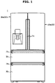
- FIG. 1 is a front view illustrating an appearance of a refrigerator according to an embodiment of the present disclosure.
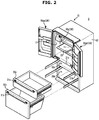
- FIG. 2 is a perspective view schematically illustrating a structure of the refrigerator according to an embodiment of the present disclosure.
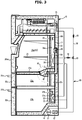
- FIG. 3 is a side vertical-sectional view illustrating the refrigerator according to an embodiment of the present disclosure.
- a refrigerator 1 may include a main body 10 whose front surface opens, a storage chamber 20 formed in the inside of the main body 10 and configured to refrigerate and/or freeze food, a door 30 configured to open or close the opened front surface of the main body 10, and a cooling device 50 configured to freeze the storage chamber 20.
- the main body 10 may form an appearance of the refrigerator 1.
- the main body 10 may include an inner casing 11 to form the storage chamber 20, and an outer casing 12 coupled to an exterior of the inner casing 11.
- An insulator 13 may be foamed between the inner casing 11 and the outer casing 12 of the main body 10 so as to prevent leakage of cool air from the storage chamber 20.
- the storage chamber 20 may be divided into a plurality of chambers.
- a first storage chamber 20a, a second storage chamber 20b, and a third storage chamber 20c may form independent storage spaces.
- the first storage chamber 20a may be referred to as an upper storage chamber
- the second storage chamber 20b may be referred to as a lower storage chamber
- the third storage chamber 20c may be referred to as an intermediate storage chamber located between the first storage chamber 20a and the second storage chamber 20b, but this can be designed and modified as needed.
- a storage temperature of each of the storage chambers 20 may be independently controlled according to the amount of cool air supplied to each of the storage chambers 20.
- the storage chamber 20 may be divided into a plurality of chambers by horizontal partitions 21a and 21b.
- the first storage chamber 20 may be classified into the first storage chamber 20a and the second storage chamber 20b by the horizontal partitions 21a.
- the storage chamber 20 may be classified into the second storage chamber 20b and the third storage chamber 20c by the horizontal partitions 21b.
- the first storage chamber 20a and the third storage chamber 20c may refrigerate food, and the second storage chamber 20b may freeze food.
- one or more shelves 23 may be provided to put food thereon.
- the number and arrangement of the storage chamber 20 are not limited to the embodiment shown in FIG. 2 .
- the storage chamber 20 may be opened or closed by the door 30.
- the first storage chamber 20a may be opened or closed by a first upper door 30aa and a second upper door 30ab.
- the first upper door 30aa and the second upper door 30ab are rotary doors that are rotatably coupled to the main body 10 to open and close the first storage chamber 20a.
- the second and third storage chambers 20b and 20c may be opened and closed by drawer doors 30b and 30c which are slidably coupled to the main body 10.
- a handle 31 may be provided on the door 30 to enable a user to easily open or close the door 30.
- a handle 31a may be extended longitudinally along and between the first upper door 30aa and the second upper door 30ab, and handles 31b and 31c may be horizontally formed in the drawer doors 30b and 30c. As a result, when the door 30 is closed, the handle 31 may look as if it is one body with the door 30.
- the number and arrangement of the door 30 are not limited to the embodiment shown in FIG. 2 .
- the cooling device 50 may include, as shown in FIG. 3 , a compressor 51 to compress refrigerants to a high pressure, a condenser 52 to condense the compressed refrigerants, expanders 54 and 55 to expand the refrigerants to a low pressure, evaporators 56 and 57 to evaporate the refrigerants, and a refrigerant pipe 58 to guide the refrigerants.
- the compressor 51 and the condenser 52 may be provided in a machine room 14 provided in rear lower space of the main body 10.
- the evaporators 56 and 57 may include the first evaporator 56 to supply the cool air to the first storage chamber 20a, and the second evaporator 57 to supply the cool air to the second storage chamber 20b.
- the first evaporator 56 may be disposed in a first cool air duct 56a formed in a rear space of the first storage chamber 20a
- the second evaporator 57 may be disposed in a second cool air duct 57a formed in a rear space of the second storage chamber 20b.
- a first blow fan 56a may be disposed to supply the cool air generated by the first evaporator 56 to the first storage chamber 20a
- a second blow fan 57b may be disposed to supply the cool air generated by the second evaporator 57 to the second storage chamber 20b.
- the refrigerant pipe 58 may guide refrigerants compressed by the compressor 51 to the first evaporator 56 and the second evaporator 57.
- a switching valve 53 may be provided to distribute refrigerants to the first evaporator 56 or the second evaporator 57.
- a third cool air duct 64 for communicating with the first evaporator 56 side and the third storage chamber 20c side may be provided between the inner casing 11 and the outer casing 12 on the rear side of the main body 10 for circulating the cool air in the third storage chamber 20c.
- the supply of the cool air to the third cool air duct 64 side may be performed by a circulation fan 63 disposed at a position close to the first evaporator 56. That is, the cool air generated from the first evaporator 56 may be supplied to the third storage chamber 20c through the third cool air duct 64 by the circulation fan 63. At this time, the cool air supplied through the third cool air duct 64 may be supplied to the third storage chamber 20c through a cool air supply device 80 provided on the rear side of the horizontal partition 21a.
- a second damper 82 protruding from the lower surface of the horizontal partition 21a and communicating with the cool air supply device 80 may be provided in a lower rear side of the horizontal partition 21a so that the cool air supplied by the cool air supply device 80 can be discharged to the third storage chamber 20c.
- the cool air supplied through the third cool air duct 64 may not be supplied to the third storage chamber 20c.
- the cool air may be supplied to the third storage chamber 20c.
- the second damper 82 may control the amount of cool air supplied to the third storage chamber 20c.
- the cool air generated by the first evaporator 56 may be supplied to the first storage chamber 20a through a first blow fan 56b.
- a first damper 81 that communicates with a passage connecting the first cool air duct 56a and the first storage chamber 20a may be provided.
- the cool air supplied through the first cool air duct 56a may be supplied to the first storage chamber 20a.
- the cool air supplied through the first cool air duct 56a may not be supplied to the first storage chamber 20a.
- the cool air that has been cooled in the first storage chamber 20a may be returned to the first evaporator 56 through an inlet (not shown) provided in the lower rear wall of the first storage chamber 20a.
- the first damper 81 may control the amount of cool air supplied to the first storage chamber 20a.
- the cool air generated from the first evaporator 56 may be introduced into the first storage chamber 20a through the first damper 81 opened through the first cool air duct 56a, and the first storage chamber 20a may be cooled.
- the cool air generated from the first evaporator 56 may be introduced into the third storage chamber 20c through the second damper 82 opened by the circulation fan 63 through the third cool air duct 64, and the third storage chamber 20c may be cooled.
- the cool air generated by the second evaporator 57 may be supplied to the second storage chamber 20b through the second blow fan 57b. That is, the cool air generated by the second evaporator 57 may be introduced into the second storage chamber 20b through an outlet (not shown) provided between the second cool air duct 57a and the second storage chamber 20b. The cool air that has been cooled in the second storage chamber 20b may be returned to the second evaporator 57 through an inlet (not shown) provided in the lower rear wall of the second storage chamber 20b.
- a first defrost heater 71 may be provided in a lower of the first evaporator 56.
- the first defrost heater 71 may be operated so that the cool air can be smoothly discharged into the first storage chamber 20a by stopping the freezing or removing the generated frost.
- the air heated by the first defrost heater 71 may be raised by natural convection and may be guided to the first damper 81 or the outlet (not shown) through the first cool air duct 56a. Since the air convection in the first cool air duct 56a maintains a high temperature, the freezing may be stopped or the frost generated in the first evaporator 56, the first damper 81, or the outlet (not shown) may be removed by the air having the high temperature, and the cool air may be smoothly supplied to the first storage chamber 20a.
- a second defrost heater 72 may be provided in a lower of the second evaporator 57.
- the second defrost heater 72 may be operated so that the cool air can be smoothly discharged into the second storage chamber 20b by stopping the freezing or the generated frost.
- the air heated by the second defrost heater 72 may be raised by natural convection and may be guided to the outlet (not shown) through the second cool air duct 57a. Since the air convection in the second cool air duct 57a maintains the high temperature, the freezing may be stopped or the frost generated in the second evaporator 57 or the outlet (not shown) may be removed by the air having the high temperature, and the cool air may be smoothly supplied to the second storage chamber 20b.
- FIG. 4 is a block diagram illustrating the refrigerator according to an embodiment of the present disclosure.
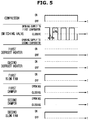
- FIG. 5 is a control graph of a cooling section before a defrosting operation of the refrigerator according to an embodiment of the present disclosure
- FIG. 6 is a control graph of a defrosting section of the refrigerator according to an embodiment of the present disclosure
- FIG. 7 is a control graph of the cooling section after the defrosting operation of the refrigerator according to an embodiment of the present disclosure.
- FIG. 8 is a view illustrating a flow of cool air when a first damper and a second damper are closed according to an embodiment of the present disclosure
- FIG. 9 is a view illustrating the flow of cool air when the first damper and the second damper are opened according to an embodiment of the present disclosure.
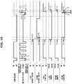
- FIG. 10 is a control graph of the entirety of a control section of the refrigerator according to an embodiment of the present disclosure.
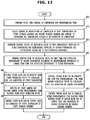
- FIGS. 11 to 13 are flowcharts illustrating a method for controlling the refrigerator according to an embodiment of the present disclosure.
- the refrigerator 1 may further include, in addition to the components shown in FIGS. 1 to 3 , a storage chamber temperature sensor 90 configured to measure the temperature of the storage chamber 20, a controller 100 configured to control the cooling device 50 according to an output of the storage chamber temperature sensor 90, and to control components included in the refrigerator 1, and a memory 110 configured to store data related to the operation of the refrigerator 1.
- a storage chamber temperature sensor 90 configured to measure the temperature of the storage chamber 20
- a controller 100 configured to control the cooling device 50 according to an output of the storage chamber temperature sensor 90, and to control components included in the refrigerator 1
- a memory 110 configured to store data related to the operation of the refrigerator 1.
- the storage chamber temperature sensor 90 may include a first storage chamber temperature sensor 91 for measuring the temperature of the first storage chamber 20a, a second storage chamber temperature sensor 92 for measuring the temperature of the second storage chamber 20b, and a third storage chamber temperature sensor 93 for measuring the temperature of the third storage chamber 20c.
- the first storage chamber temperature sensor 91 may be provided in the first storage chamber 20a to measure the temperature of the first storage chamber 20a and to output an electrical signal corresponding to the temperature of the first storage chamber 20a to the controller 100.
- the first storage chamber temperature sensor 91 may be a thermistor whose electrical resistance value changes according to the temperature.
- the second storage chamber temperature sensor 92 may be provided in the second storage chamber 20b to measure the temperature of the second storage chamber 20b and to output an electrical signal corresponding to the temperature of the second storage chamber 20b to the controller 100.
- the second storage chamber temperature sensor 92 may be the thermistor whose electrical resistance value changes according to the temperature.
- the third storage chamber temperature sensor 93 may be provided in the third storage chamber 20c to measure the temperature of the third storage chamber 20c and to output an electrical signal corresponding to the temperature of the third storage chamber 20c to the controller 100.
- the third storage chamber temperature sensor 93 may be the thermistor whose electrical resistance value changes according to the temperature.
- the memory 110 may store control programs and control data for controlling operations of the refrigerator 1, and various application programs and application data for performing various functions according to the user's inputs. Also, the memory 110 may temporarily store an output of the storage chamber temperature sensor 90 and an output of the controller 100.
- the memory 110 may include volatile memory, such as Static-Random Access Memory (S-RAM) and Dynamic-Random Access Memory (D-RAM), for temporarily storing data. Also, the memory 110 may include non-volatile memory, such as Read Only Memory (ROM), Erasable Programmable Read Only Memory (EPROM), and Electrically Erasable Programmable Read Only Memory (EEPROM), for storing data for a long period of time.
- volatile memory such as Static-Random Access Memory (S-RAM) and Dynamic-Random Access Memory (D-RAM)
- ROM Read Only Memory
- EPROM Erasable Programmable Read Only Memory
- EEPROM Electrically Erasable Programmable Read Only Memory
- the controller 100 may include various logic circuits and operation circuits, and process data according to a program provided from the memory 110, and generate a control signal according to the result of the processing.
- the controller 100 may process an output of the storage chamber temperature sensor 90, and generate a cooling control signal for controlling the compressor 51 and the switching valve 53 of the cooling device 50 in order to cool the storage chamber 20.
- the controller 100 may control the components included in the refrigerator 1 according to the temperature of the storage chamber 20 or the like.
- operations of the refrigerator 1, which will be described below, may be performed according to the control of the controller 100.
- the refrigerator 1 may perform a cooling control for supplying the cool air to the storage chamber 20 according to the control of the controller 100.
- the cooling control corresponds to a pre-cooling control for lowering the temperature of the storage chamber 20 in advance before the defrosting operation of the refrigerator 1 is performed.
- defrosting heat generated by the first defrost heater 71 and the second defrost heater 72 enters the storage chamber 20 to prevent the temperature inside the storage chamber from rising above a set temperature. That is, even if the defrosting heat enters the storage chamber 20 by lowering the temperature of the storage chamber 20 before the defrosting operation of the refrigerator 1, the freshness of the food stored in the storage chamber 20 may be maintained by preventing the temperature of the storage chamber 20 from rising above the set temperature.
- the controller 100 may control the compressor 51 to compress the refrigerant to a high pressure for the cooling control. That is, the controller 100 may adjust the number of revolutions of the compressor 51 to a predetermined number of revolutions so that the temperatures of the first and second storage chambers 20a and 20b are lowered to a predetermined temperature. At this time, the number of revolutions of the compressor 51 controlled by the controller 100 may vary depending on a set value or a stored data. That is, the controller 100 may adjust the number of revolutions of the compressor 51 based on the temperature of the storage chamber 20 detected by the storage chamber temperature sensor 90. Further, the number of rotations of the compressor 51 may be adjusted to the set value for maintaining an optimum temperature based on the optimum temperature for storing the food stored in the storage chamber 20.
- the controller 100 may determine the number of revolutions of the compressor 51 by comparing the temperatures of the respective storage chambers 20 detected by the first storage chamber temperature sensor 91, the second storage chamber temperature sensor 92, and the third storage chamber temperature sensor 93 with temperature data pre-stored in the memory 110.
- the temperature data pre-stored in the memory 110 may be stored in the storage chamber 20 at the lowest temperature to prevent the refrigerated food from freezing and the quality of the food being impaired.
- the refrigerant compressed by the compressor 51 may be supplied to at least one of the first evaporator 56 and the second evaporator 57 by the switching valve 53.
- the controller 100 may generate the control signal for controlling the switching valve 53 so that the refrigerant supplied to at least one of the first evaporator 56 and the second evaporator 57 is distributed according to a predetermined reference.
- the predetermined reference for the switching valve 53 to distribute the refrigerant may be stored in the memory 110.
- the reference may vary depending on the set temperature for lowering the temperature of each of the storage chambers 20 or the size of each of the storage chambers 20. That is, the controller 100 may control the switching valve 53 to distribute the refrigerant corresponding to the predetermined optimum temperature of the storage chamber 20, and adjust the refrigerant distribution ratio of the switching valve 53 by comparing the temperature of the storage chamber 20 detected by the storage chamber temperature sensor 90 with the predetermined optimum temperature.
- the first storage chamber 20a is connected to the third storage chamber 20c through the third coolant duct 64 and the space to be cooled by the cool air generated by the first evaporator 56 is larger than the space of the second storage chamber 20b where the cool air generated by the second evaporator 57 is to be cooled. Accordingly, the controller 100 may adjust the refrigerant distribution ratio of the switching valve 53 such that the temperature of the first storage chamber 20a connected to the third storage chamber 20c becomes lower than the temperature of the second storage chamber 20b.
- the controller 100 may generate the control signal for controlling the opening time of the switching valve 53 so that the time for supplying the refrigerant to the first evaporator according to the predetermined reference is longer than the time for supplying the refrigerant to the second evaporator.
- the controller 100 may control the switching valve 53 such that an opening time t u for supplying the refrigerant to the first evaporator 56 is longer than an opening time t l for supplying the refrigerant to the second evaporator 57.
- the refrigerant supply distribution ratio to the first evaporator 56 and the second evaporator 57, that is, t u : t l may be changed according to the embodiment.
- the controller 100 may control the switching valve 53 such that the opening degree for supplying the refrigerant to the first evaporator 56 is larger than the opening degree for supplying the refrigerant to the second evaporator 57.
- the switching valve 53 may supply the refrigerant to the first evaporator 56 and the second evaporator 57 according to the control of the controller 100 and the first evaporator 56 and the second evaporator 57 may generate the cool air.
- the first damper 81 and the second damper 82 may be opened in a cooling control section in which cool air is supplied to the storage chamber 20 according to the control of the controller 100 prior to the defrosting operation.
- the cool air generated by the first evaporator 56 can be supplied to the first storage chamber 20a through the first damper 81 by the operation of the first blow fan 56b, and the cool air passing through the third cool air duct 64 by the operation of the circulation fan 63 may be supplied to the third storage chamber 20c through the second damper 82.
- the cool air generated by the second evaporator 57 may be supplied to the second storage chamber 20b by the operation of the second blow fan 57b.
- the controller 100 may generate the control signal so that the switching valve 53 is distributed in accordance with the predetermined reference to the refrigerant supplied to the first evaporator 56 and the second evaporator 57, and the temperatures of the first storage chamber 20a and the second storage chamber 20b connected to the third storage chamber 20c may be lowered to the predetermined temperature.
- the refrigerator 1 may perform the defrosting operation for controlling the freezing or the frost generated in the evaporator, the outlet, etc., according to the control of the controller 100.
- the air heated by the first defrost heater 71 may be raised by natural convection and may be guided to the first damper 81 or the outlet (not shown) through the first cool air duct 56a. Since the air convection in the first cool air duct 56a maintains a high temperature, the freezing may be stopped or the frost generated in the first evaporator 56, the first damper 81, or the outlet (not shown) may be removed by the air having the high temperature, and the cool air may be smoothly supplied to the first storage chamber 20a.
- the air heated by the second defrost heater 72 may be raised by natural convection and may be guided to the outlet (not shown) through the second cool air duct 57a. Since the air convection in the second cool air duct 57a maintains the high temperature, the freezing may be stopped or the frost generated in the second evaporator 57 or the outlet (not shown) may be removed by the air having the high temperature, and the cool air may be smoothly supplied to the second storage chamber 20b.
- the first damper 81 and the second damper 82 may be closed according to the control of the controller 100 to prevent the high temperature air heated by the defrost heater from flowing into the storage chamber 20 while the defrosting operation is being performed.
- Power consumption [W] of such defrost heater may be different according to the specification, and the defrosting capability may also differ depending on the difference of the power consumption.
- the freezing or frost may occur more frequently in the configuration of the refrigerator 1 than in the case of the storage chamber 20 for performing only the refrigeration operation.
- the power consumption of the defrost heater provided in the lower part of the evaporator provided in the rear of the storage chamber for performing the freezing operation is larger than the power consumption of the defrost heater provided in the lower part of the evaporator provided in the rear of the storage chamber for performing only the refrigeration operation, and also a large defrosting capability.
- the first storage chamber 20a and the third storage chamber 20c may perform the refrigeration operation and the second storage chamber 20b may perform the refrigeration operation and the freezing operation, for example.
- the cooling operation mode of each of the storage chambers 20 is not limited, and various design changes are possible.
- the power consumption of the second defrost heater 72 provided at the lower part of the second evaporator 57 provided at the rear of the second storage chamber 20b may be larger than the power consumption of the first defrost heater 71 provided at the lower part of the first evaporator 56 provided at the rear of the first storage chamber 20a.
- the first defrost heater 71 and the second defrost heater 72 may be operated for defrosting and may supply heat for stopping the freezing or removing the frost.
- the first defrost heater 71 and the second defrost heater 72 may stop the operation when the temperature reaches a defrosting completion point at which the freezing is stopped or the frost is removed according to the predetermined reference.
- the defrosting operation by the second defrost heater 72 may reach the defrosting completion point first than the defrosting operation by the first defrost heater 71. Therefore, the second defrost heater 72 may be stopped before the first defrost heater 71 is started.
- the air temperature of the second cool air duct 57a and the second storage chamber 20b provided with the second defrost heater 72 in which the operation is stopped may be increased over time.
- the defrosting operation stage of the refrigerator 1 may include a natural defrosting stage in which the blow fan is operated to stop the freezing or remove the frost before the defrost heater is operated to perform the defrosting.
- the controller 100 may control the first blow fan 56b and the second blow fan 57b for the natural defrosting. That is, as shown in FIG. 6 , the controller 100 may operate the first blow fan 56b for a first reference time t1 to perform the natural defrosting operation on the first storage chamber 20a. At this time, data for the first reference time t1 may be preset and stored in the memory 110.
- the controller 100 may generate the control signal for operating the first defrost heater 71 after the first reference time t1 when the first blow fan 56b is operated.
- the first defrost heater 71 may operate based on the control signal generated by the controller 100 from a point t a when the first blow fan 56b stops the operation to remove the frost on the surface of the first evaporator 56.
- the controller 100 may control the first damper 81 and the second damper 82 so that the first blow fan 56b stops the operation and to be closed from the point when the first defrost heater 71 starts to operate.
- the controller 100 may operate the second blow fan 57b for a second reference time t2 to perform the natural defrosting for the second storage chamber 20b.
- the controller 100 may generate the control signal for operating the second defrost heater 72 after the second reference time t2 when the second blow fan 57b is operated.
- the second defrost heater 72 may operate based on the control signal generated by the controller 100 from a point t b at when the second blow fan 57b stops the operation to remove the frost on the surface of the second evaporator 57.
- the data for the second reference time t2 may be preset and stored in the memory 110.
- the second reference time t2 may be longer than the first reference time t1 by a predetermined time t x .
- the controller 100 may delay the operating point t b of the second defrost heater 72 by the predetermined time t x than the operating point t a of the first defrost heater 71, the defrosting operation by the second defrost heater 72 is completed first and the temperature of the second storage chamber 20b may be prevented from rising.
- the operation of the compressor 51 may be stopped and the switching valve 53 may be closed according to the control of the controller 100.
- controller 100 may transmit the control signal for causing the operation of the first defrost heater 71 and the second defrost heater 72 to be stopped at the same time, various embodiments may exits depending on the change in the predetermined defrosting completion point.
- the refrigerator 1 may perform the cooling control for supplying the cool air to the storage chamber 20 according to the control of the controller 100. This is to lower the temperature of the storage chamber 20 by stopping the cooling operation during the defrosting operation, in contrast to the pre-cooling control shown in FIG. 5 .
- the controller 100 may control the compressor 51 to compress the refrigerant to a high pressure. That is, the controller 100 may adjust the number of revolutions of the compressor 51 to the predetermined number of revolutions so that the temperatures of the first and second storage chambers 20a and 20b are lowered to the predetermined temperature. In this case, the number of revolutions of the compressor 51 controlled by the controller 100 may vary depending on the set value or the stored data.
- the compressor 51 may be stopped even if the defrosting operation is completed for the predetermined time before the controller 100 starts the operation of controlling the compressor 51 to compress the refrigerant.
- Control of the compressor 51 to stop for the predetermined time may be referred to as a pause time control, which is the control for stability of the operation of the compressor 51 corresponding to the increased heat load of the storage chamber 20.
- the time required for the pause time control may vary depending on the set value or the stored data, and the temperature rise of the storage chamber 20 may be minimized as the pause time is minimized.
- the refrigerant compressed by the compressor 51 may be supplied to at least one of the first evaporator 56 and the second evaporator 57 by the switching valve 53.
- the controller 100 may generate the control signal to control the switching valve 53 such that the refrigerant supplied to at least one of the first evaporator 56 and the second evaporator 57 is distributed according to the predetermined reference.
- the predetermined reference for the switching valve 53 to distribute the refrigerant may be stored in the memory 110.
- the reference may vary depending on the degree to which the temperature of each of the storage chambers 20 rises during the defrosting operation. That is, the controller 100 may control the switching valve 53 to distribute the refrigerant corresponding to the predetermined optimum temperature of the storage chamber 20, and adjust the refrigerant distribution ratio of the switching valve 53 by comparing the temperature of the storage chamber 20 detected by the storage chamber temperature sensor 90 with the predetermined optimum temperature.
- the temperature of the second storage chamber 20b may be higher than the temperatures of the first storage chamber 20a and the third storage chamber 20c when the defrosting operation is completed.
- the controller 100 may adjust the refrigerant distribution ratio of the switching valve 53 such that the amount of cool air supplied to the second storage chamber 20b is larger than the amount of cool air supplied to the first storage chamber 20a .
- the controller 100 may generate the control signal to control the opening time of the switching valve 53 such that the time for supplying the refrigerant to the second evaporator 57 is longer than the time for supplying the refrigerant to the first evaporator 56 according to the predetermined reference.
- the controller 100 may control the switching valve 53 such that the opening time t l for supplying the refrigerant to the second evaporator 57 is longer than the opening time t u for supplying the refrigerant to the first evaporator 56.
- the refrigerant supply distribution ratio to the second evaporator 57 and the first evaporator 56 may be changed according to the embodiment.
- the controller 100 may control the switching valve 53 such that the opening degree for supplying the refrigerant to the second evaporator 57 is larger than the opening degree for supplying the refrigerant to the first evaporator 56.
- the switching valve 53 may supply the refrigerant to the first evaporator 56 and the second evaporator 57 according to the control of the controller 100 and the first evaporator 56 and the second evaporator 57 may generate the cool air.
- the evaporator and the blow fan may not be operated for the predetermined time so that the defrosting heat inside the evaporator does not enter the storage chamber 20, and the refrigerant may be supplied to the evaporator by operating the compressor 51 and the switching valve 53.
- the blow fan does not operate, even if the refrigerant is supplied to the stationary evaporator by the switching valve 53 and the evaporator is cooled, or the cool air is generated by the evaporator, the cool air may stay in the lower part of the duct and relatively hot air may stay in the upper part of the duct. In this case, when the damper is opened while the blow fan is directly operated, the hot air staying in the upper part may flow into the storage chamber 20. Therefore, it is necessary to mix the cool air and the hot air inside the duct by operating the blow fan before opening the damper.
- the cool air by the first evaporator 56 may stay in the lower part of the first cool air duct 56a, and the relatively hot air may stay in the upper part of the first cool air duct 56a.
- the controller 100 may control the first damper 81 and the second damper 82 to be opened after the first blow fan 56b operates for the predetermined time without opening the first damper 81 and the second damper 82 as soon as the operation of the first blow fan 56b is started.
- the controller 100 may control the first blow fan 56b to be operated from a first operating point t c , and may cause the cool air generated by the first evaporator 56 to circulate in the first cool air duct 56a for a predetermined time t y as shown in FIG. 8 . That is, the controller 100 may mix the cool air generated by the first evaporator 56 so that the cool air located at the lower end of the first cool air duct 56a can move to the upper end.
- the controller 100 may control the first damper 81 and the second damper 82 to be closed before the predetermined time t y elapses from the first operating point t c of the first blow fan 56b.
- the controller 100 may control the first damper 81 and the second damper 82 to be opened after the predetermined time t y elapses from the first operating point t c of the first blow fan 56b.
- the controller 100 may control the first blow fan 56b so that the cool air generated by the first evaporator 56 is supplied to the first storage chamber 20a as shown in FIG. 9 .
- the controller 100 may control the circulation fan 63 so that the cool air generated by the first evaporator 56 is supplied to the third storage chamber 20c through the third cool air duct 64 as shown in FIG. 9 .
- the predetermined time t y in which only the first blow fan 56b is operated while the first damper 81 and the second damper 82 are closed may vary according to the set value or the stored data.
- the cool air by the second evaporator 57 may stay in the lower part of the second cool air duct 57a, and the relatively hot air may stay in the upper part of the second cool air duct 57a.
- the controller 100 may control the second blow fan 57b to be operated from a second operating point td for a predetermined time t z , and may cause the cool air generated by the second evaporator 57 to circulate in the second cool air duct 57a for the predetermined time t z as shown in FIG. 8 .
- the controller 100 may mix the cool air generated by the second evaporator 57 so that the cool air located at the lower end of the second cool air duct 57a can move to the upper end.
- the controller 100 may control the second blow fan 57b for the predetermined time t z to circulate the cool air.
- the controller 100 may control the second blow fan 57b to operate at a point t g at which a predetermined time t f elapses from a stopped point t e so that the cool air generated by the second evaporator 57 is supplied to the second storage chamber 20b.
- the controller 100 may delay the opening time of the first damper 81 and the second damper 82, and may control the first blow fan 56b and the second blow fan 57b so that the cool air can be entered into the first storage chamber 20a, the second storage chamber 20b and the third storage chamber 20c, by circulating the cool air generated in the first evaporator 56 and the second evaporator 57 in the first cool air duct 56a and the second cool air duct 57a.
- the controller 100 may adjust the number of revolutions of the compressor 51 so that the temperatures of the first and second storage chambers 20a and 20b are lowered to the predetermined temperature (200). That is, the controller 100 may adjust the number of revolutions of the compressor 51 based on the temperature of the storage chamber 20 detected by the storage chamber temperature sensor 90. Further, the number of rotations of the compressor 51 may be adjusted to the set value for maintaining the optimum temperature based on the optimum temperature for storing the food stored in the storage chamber 20.
- the controller 100 may compare the temperature of each of the storage chambers 20 detected by the first storage chamber temperature sensor 91, the second storage chamber temperature sensor 92, and the third storage chamber temperature sensor 93 with the temperature data pre-stored in the memory 110, and determine the number of revolutions of the compressor 51.
- the temperature data pre-stored in the memory 110 may be stored in the storage chamber 20 at a minimum temperature to prevent the refrigerated food from freezing and not damaging the quality of the food.
- the controller 100 may generate the control signal to control the switching valve 53 such that the refrigerant supplied to the first evaporator 56 and the refrigerant supplied to the second evaporator 57 are distributed according to the predetermined reference (210).
- the controller 100 may generate the control signal for controlling the opening time of the switching valve 53 so that the time for supplying the refrigerant to the first evaporator 56 according to the predetermined reference is longer than the time for supplying the refrigerant to the second evaporator 57 (220).
- the controller 100 may perform the pre-cooling control to lower the temperatures of the first and second storage chambers 20a and 20b based on the generated control signal of the switching valve 53 (230), and may lower the temperatures of the first and second storage chambers 20a and 20b connected to the third storage chamber 20c to the predetermined temperature.
- the controller 100 may perform the natural defrosting on the first storage chamber 20a and the second storage chamber 20b by operating the first blow fan 56b for the first reference time t1 and the second blow fan 57b for the second reference time t2 (300).
- the defrosting operation stage of the refrigerator 1 may include the natural defrosting stage of stopping the freezing or removing the frost by operating the blow fan before operating the defrost heater and performing the defrosting.
- the controller 100 may control the first blow fan 56b to stop the operation after the first reference time t1 elapses (310), and the first damper 81 and the second damper 82 may be closed after the elapse of the reference time t l (320). Also, the first defrost heater 71 may operate after the elapse of the first reference time t1 to perform the defrosting operation (330).
- the first defrost heater 71 may operate from the point t a at which the first blow fan 56b stops the operation based on the control signal generated by the controller 100 to remove the frost on the surface of the first evaporator 56.
- the controller 100 may control the second blow fan 57b to stop the operation after the second reference time t2 elapses (340), and the second defrost heater 72 may operate after the elapse of the second reference time t2 to perform the defrosting operation (350).
- the second defrost heater 72 may operate from the point t b at which the second blow fan 57b stops the operation based on the control signal generated by the controller 100 to remove the frost on the surface of the second evaporator 57.
- controller 100 may transmit the control signal to stop the operation of the first defrost heater 71 and the second defrost heater 72 simultaneously (360).
- the controller 100 may delay the operating point t b of the second defrost heater 72 by the predetermined time t x than the operating point t a of the first defrost heater 71, and the defrosting operation by the second defrost heater 72 is completed first and the temperature of the second storage chamber 20b may be prevented from rising.
- the refrigerator 1 may perform the cooling control for supplying the cool air to the storage chamber 20 according to the control of the controller 100.
- the controller 100 may perform the pause time control to cause the compressor 51 to stop for the predetermined time (400).
- the controller 100 may control the compressor 51 to compress the refrigerant to a high pressure and adjust the number of revolutions of the compressor 51 to the predetermined number of revolutions so that the temperatures of the first and second storage chambers 20a and 20b are lowered to the predetermined temperature (410).
- the controller 100 may also generate the control signal to control the switching valve 53 such that the refrigerant supplied to at least one of the first evaporator 56 and the second evaporator 57 is distributed according to the predetermined reference (420). That is, the controller 100 may generate the control signal for controlling the opening time of the switching valve 53 so that the time for supplying the refrigerant to the second evaporator 57 according to the predetermined reference is longer than the time for supplying the refrigerant to the first evaporator 56 (430).
- the controller 100 may control the first blow fan 56b to be operated from the first operating point t c , and may cause the cool air generated by the first evaporator 56 to circulate in the first cool air duct 56a for the predetermined time t y (440).
- the controller 100 may also control the first damper 81 and the second damper 82 to be opened after the predetermined time t y elapses from the first operating point t c of the first blow fan 56b (450).
- the controller 100 may control the first blow fan 56b so that the cool air generated by the first evaporator 56 is supplied to the first storage chamber 20a (460).
- the controller 100 may control the second blow fan 57b to be operated from a second operating point td for the predetermined time t z , and may cause the cool air generated by the second evaporator 57 to circulate in the second cool air duct 57a for the predetermined time t z (445). That is, the controller 100 may mix the cool air generated by the second evaporator 57 so that the cool air located at the lower end of the second cool air duct 57a can move to the upper end.
- the controller 100 may control the second blow fan 57b for the predetermined time t z to circulate the cool air.
- the controller 100 may control the second blow fan 57b to operate at the point t g at which the predetermined time t f elapses from the stopped point t e so that the cool air generated by the second evaporator 57 is supplied to the second storage chamber 20b (455).
- the refrigerator 1 can prevent the temperature of the storage chamber 20 from increasing due to the defrosting heat generated in the defrosting process, and perform an efficient refrigeration and freezing operation.
- the refrigerator and the method for controlling the same can prevent the quality and taste of the food stored in the storage chamber from being changed due to the temperature increase of the storage chamber by the defrosting heat generated during the defrosting process.
- the defrosting heat can be prevented from entering the storage chamber by changing the control algorithm for the existing configuration without adding a separate configuration of the refrigerator.
- the embodiments of the present disclosure may be implemented in the form of recording media for storing instructions to be carried out by a computer.
- the instructions may be stored in the form of program codes, and when executed by a processor, may generate program modules to perform operations in the embodiments of the present disclosure.
- the recording media may correspond to computer-readable recording media.
- the computer-readable recording medium includes any type of recording medium having data stored thereon that may be thereafter read by a computer.
- it may be a ROM, a RAM, a magnetic tape, a magnetic disk, a flash memory, an optical data storage device, etc.
Landscapes
- Engineering & Computer Science (AREA)
- Physics & Mathematics (AREA)
- Mechanical Engineering (AREA)
- Thermal Sciences (AREA)
- General Engineering & Computer Science (AREA)
- Chemical & Material Sciences (AREA)
- Combustion & Propulsion (AREA)
- Defrosting Systems (AREA)
- Cold Air Circulating Systems And Constructional Details In Refrigerators (AREA)
- Devices That Are Associated With Refrigeration Equipment (AREA)
Applications Claiming Priority (2)
| Application Number | Priority Date | Filing Date | Title |
|---|---|---|---|
| KR1020170108709A KR102418005B1 (ko) | 2017-08-28 | 2017-08-28 | 냉장고 및 그 제어방법 |
| PCT/KR2018/009027 WO2019045306A1 (ko) | 2017-08-28 | 2018-08-08 | 냉장고 및 그 제어방법 |
Publications (2)
| Publication Number | Publication Date |
|---|---|
| EP3660431A1 true EP3660431A1 (de) | 2020-06-03 |
| EP3660431A4 EP3660431A4 (de) | 2020-10-21 |
Family
ID=65525724
Family Applications (1)
| Application Number | Title | Priority Date | Filing Date |
|---|---|---|---|
| EP18849884.4A Pending EP3660431A4 (de) | 2017-08-28 | 2018-08-08 | Kühlschrank und steuerungsverfahren dafür |
Country Status (4)
| Country | Link |
|---|---|
| US (1) | US11397041B2 (de) |
| EP (1) | EP3660431A4 (de) |
| KR (1) | KR102418005B1 (de) |
| WO (1) | WO2019045306A1 (de) |
Families Citing this family (8)
| Publication number | Priority date | Publication date | Assignee | Title |
|---|---|---|---|---|
| KR102833826B1 (ko) * | 2018-11-27 | 2025-07-15 | 엘지전자 주식회사 | 냉장고 및 그의 제어방법 |
| US20220011036A1 (en) * | 2018-12-28 | 2022-01-13 | Hefei Midea Refrigerator Co., Ltd. | Control method and device for refrigerator, and refrigerator |
| KR102925850B1 (ko) * | 2019-09-02 | 2026-02-11 | 엘지전자 주식회사 | 언더 카운터형 냉장고 및 그 제어방법 |
| CN112944771B (zh) * | 2019-11-26 | 2023-09-29 | 青岛海尔特种电冰柜有限公司 | 风冷设备的控制方法及风冷设备 |
| KR102279054B1 (ko) | 2019-12-09 | 2021-07-19 | 엘지전자 주식회사 | 냉장고 |
| KR20210130061A (ko) * | 2020-04-21 | 2021-10-29 | 삼성전자주식회사 | 냉장고 및 그 제어 방법 |
| CN113915845A (zh) * | 2020-07-08 | 2022-01-11 | 青岛海尔特种电冰箱有限公司 | 用于冷藏冷冻装置的控制方法及冷藏冷冻装置 |
| CN114593553B (zh) * | 2022-03-30 | 2022-11-15 | 西安交通大学 | 一种冰箱的恒温间室及其控制方法和冰箱 |
Family Cites Families (21)
| Publication number | Priority date | Publication date | Assignee | Title |
|---|---|---|---|---|
| KR100221881B1 (ko) * | 1997-08-26 | 1999-09-15 | 전주범 | 냉장고의 저소음 운전 제어 방법 |
| JP3636602B2 (ja) * | 1998-09-16 | 2005-04-06 | 株式会社東芝 | 冷蔵庫 |
| KR100577420B1 (ko) * | 1999-12-27 | 2006-05-08 | 삼성전자주식회사 | 냉장고 및 그 제어방법 |
| JP2001336837A (ja) | 2000-05-26 | 2001-12-07 | Matsushita Electric Ind Co Ltd | 暖房装置 |
| KR100350419B1 (ko) * | 2000-05-31 | 2002-08-28 | 삼성전자 주식회사 | 김치냉장고 및 그 제어방법 |
| KR100468125B1 (ko) | 2002-07-04 | 2005-01-26 | 삼성전자주식회사 | 다실형 김치 저장고의 제어방법 |
| JP2004077000A (ja) * | 2002-08-14 | 2004-03-11 | Toshiba Corp | 冷蔵庫 |
| KR20040022643A (ko) | 2002-09-09 | 2004-03-16 | 삼성전자주식회사 | 냉장고의 과냉방지시스템 및 과냉방지방법 |
| KR101145223B1 (ko) * | 2005-09-01 | 2012-05-25 | 삼성전자주식회사 | 냉장고의 운전제어방법 |
| KR20070112664A (ko) * | 2006-05-22 | 2007-11-27 | 엘지전자 주식회사 | 냉장고의 냉매밸브 제어방법 |
| WO2008111162A1 (ja) * | 2007-03-13 | 2008-09-18 | Hoshizaki Denki Kabushiki Kaisha | 冷却貯蔵庫及びその運転方法 |
| KR101387522B1 (ko) * | 2007-11-05 | 2014-04-23 | 엘지전자 주식회사 | 냉장고 및 그 제어방법 |
| KR101641225B1 (ko) * | 2009-06-30 | 2016-07-20 | 엘지전자 주식회사 | 냉장고의 온도 제어방법 및 그를 이용한 냉장고 |
| US8459049B2 (en) * | 2010-08-30 | 2013-06-11 | General Electric Company | Method and apparatus for controlling refrigerant flow |
| KR101849103B1 (ko) * | 2011-10-06 | 2018-06-01 | 삼성전자주식회사 | 냉장고 및 그 제어방법 |
| KR102126401B1 (ko) | 2013-12-17 | 2020-06-24 | 엘지전자 주식회사 | 냉장고 및 냉장고 제어 방법 |
| KR20150110020A (ko) * | 2014-03-23 | 2015-10-02 | 주식회사 대유위니아 | 냉장고의 초기 운전방법 |
| KR102267881B1 (ko) * | 2014-12-01 | 2021-06-23 | 삼성전자주식회사 | 냉장고 |
| KR20170029346A (ko) | 2015-09-07 | 2017-03-15 | 엘지전자 주식회사 | 냉장고 제어 방법 |
| US9920971B2 (en) * | 2015-09-23 | 2018-03-20 | International Business Machines Corporation | Refrigerated transport temperature regulation |
| KR102641371B1 (ko) * | 2015-12-17 | 2024-02-28 | 삼성전자주식회사 | 냉장고 |
-
2017
- 2017-08-28 KR KR1020170108709A patent/KR102418005B1/ko active Active
-
2018
- 2018-08-08 US US16/643,118 patent/US11397041B2/en active Active
- 2018-08-08 WO PCT/KR2018/009027 patent/WO2019045306A1/ko not_active Ceased
- 2018-08-08 EP EP18849884.4A patent/EP3660431A4/de active Pending
Also Published As
| Publication number | Publication date |
|---|---|
| WO2019045306A1 (ko) | 2019-03-07 |
| KR102418005B1 (ko) | 2022-07-07 |
| KR20190023257A (ko) | 2019-03-08 |
| US20200393179A1 (en) | 2020-12-17 |
| EP3660431A4 (de) | 2020-10-21 |
| US11397041B2 (en) | 2022-07-26 |
Similar Documents
| Publication | Publication Date | Title |
|---|---|---|
| US11397041B2 (en) | Refrigerator and controlling method thereof | |
| KR100453236B1 (ko) | 다용도실을 구비한 냉장고 및 그 제어방법 | |
| KR101387522B1 (ko) | 냉장고 및 그 제어방법 | |
| US10088218B2 (en) | Refrigerator and control method thereof | |
| JP5043938B2 (ja) | 冷気循環装置を有する冷蔵庫及び冷気循環の制御方法 | |
| WO2018121592A1 (zh) | 恒温冰箱及其控制方法 | |
| US11835291B2 (en) | Refrigerator and method for controlling the same | |
| JP2004301493A (ja) | 冷蔵庫の温度制御方法 | |
| KR20180055242A (ko) | 냉장고 및 그 제어방법 | |
| US20200166259A1 (en) | Refrigerator and method for controlling the same | |
| US11906243B2 (en) | Refrigerator and method of controlling the same | |
| JP2016223752A (ja) | 冷蔵庫 | |
| KR102440226B1 (ko) | 냉장고 | |
| KR101897332B1 (ko) | 냉장고 및 냉장고의 냉장실 정온제어방법 | |
| KR101804629B1 (ko) | 냉장고 및 냉장고 제어 방법 | |
| KR20190070778A (ko) | 냉장고 | |
| KR20100019857A (ko) | 김치냉장고의 냉매순환장치 및 냉매순환방법 | |
| KR20100034080A (ko) | 냉장고 및 그 제어방법 | |
| KR102518816B1 (ko) | 냉장고 및 그 제어 방법 | |
| JP6309156B2 (ja) | 冷蔵庫 | |
| US20200116424A1 (en) | Refrigerator and method of controlling the same | |
| KR101099497B1 (ko) | 냉장고 | |
| KR100913142B1 (ko) | 냉장고 및 그의 제어방법 | |
| KR100826934B1 (ko) | 냉장고 및 그 운전제어방법 | |
| JP2007120913A (ja) | 冷蔵庫 |
Legal Events
| Date | Code | Title | Description |
|---|---|---|---|
| STAA | Information on the status of an ep patent application or granted ep patent |
Free format text: STATUS: THE INTERNATIONAL PUBLICATION HAS BEEN MADE |
|
| PUAI | Public reference made under article 153(3) epc to a published international application that has entered the european phase |
Free format text: ORIGINAL CODE: 0009012 |
|
| STAA | Information on the status of an ep patent application or granted ep patent |
Free format text: STATUS: REQUEST FOR EXAMINATION WAS MADE |
|
| 17P | Request for examination filed |
Effective date: 20200226 |
|
| AK | Designated contracting states |
Kind code of ref document: A1 Designated state(s): AL AT BE BG CH CY CZ DE DK EE ES FI FR GB GR HR HU IE IS IT LI LT LU LV MC MK MT NL NO PL PT RO RS SE SI SK SM TR |
|
| AX | Request for extension of the european patent |
Extension state: BA ME |
|
| RIC1 | Information provided on ipc code assigned before grant |
Ipc: F25B 41/04 20060101ALI20200609BHEP Ipc: F25D 29/00 20060101AFI20200609BHEP Ipc: F25D 11/02 20060101ALI20200609BHEP Ipc: F25D 21/08 20060101ALI20200609BHEP |
|
| A4 | Supplementary search report drawn up and despatched |
Effective date: 20200922 |
|
| RIC1 | Information provided on ipc code assigned before grant |
Ipc: F25D 11/02 20060101ALI20200916BHEP Ipc: F25D 29/00 20060101AFI20200916BHEP Ipc: F25B 41/04 20060101ALI20200916BHEP Ipc: F25D 21/08 20060101ALI20200916BHEP |
|
| DAV | Request for validation of the european patent (deleted) | ||
| DAX | Request for extension of the european patent (deleted) | ||
| STAA | Information on the status of an ep patent application or granted ep patent |
Free format text: STATUS: EXAMINATION IS IN PROGRESS |
|
| 17Q | First examination report despatched |
Effective date: 20210630 |