EP3660452B1 - Positionierungssystem und positionierungsverfahren - Google Patents
Positionierungssystem und positionierungsverfahren Download PDFInfo
- Publication number
- EP3660452B1 EP3660452B1 EP18841158.1A EP18841158A EP3660452B1 EP 3660452 B1 EP3660452 B1 EP 3660452B1 EP 18841158 A EP18841158 A EP 18841158A EP 3660452 B1 EP3660452 B1 EP 3660452B1
- Authority
- EP
- European Patent Office
- Prior art keywords
- optical pattern
- region
- target
- sub
- projection device
- Prior art date
- Legal status (The legal status is an assumption and is not a legal conclusion. Google has not performed a legal analysis and makes no representation as to the accuracy of the status listed.)
- Active
Links
Images


Classifications
-
- G—PHYSICS
- G01—MEASURING; TESTING
- G01C—MEASURING DISTANCES, LEVELS OR BEARINGS; SURVEYING; NAVIGATION; GYROSCOPIC INSTRUMENTS; PHOTOGRAMMETRY OR VIDEOGRAMMETRY
- G01C11/00—Photogrammetry or videogrammetry, e.g. stereogrammetry; Photographic surveying
-
- G—PHYSICS
- G01—MEASURING; TESTING
- G01C—MEASURING DISTANCES, LEVELS OR BEARINGS; SURVEYING; NAVIGATION; GYROSCOPIC INSTRUMENTS; PHOTOGRAMMETRY OR VIDEOGRAMMETRY
- G01C21/00—Navigation; Navigational instruments not provided for in groups G01C1/00 - G01C19/00
- G01C21/20—Instruments for performing navigational calculations
- G01C21/206—Instruments for performing navigational calculations specially adapted for indoor navigation
-
- G—PHYSICS
- G01—MEASURING; TESTING
- G01C—MEASURING DISTANCES, LEVELS OR BEARINGS; SURVEYING; NAVIGATION; GYROSCOPIC INSTRUMENTS; PHOTOGRAMMETRY OR VIDEOGRAMMETRY
- G01C11/00—Photogrammetry or videogrammetry, e.g. stereogrammetry; Photographic surveying
- G01C11/02—Picture taking arrangements specially adapted for photogrammetry or photographic surveying, e.g. controlling overlapping of pictures
-
- G—PHYSICS
- G01—MEASURING; TESTING
- G01C—MEASURING DISTANCES, LEVELS OR BEARINGS; SURVEYING; NAVIGATION; GYROSCOPIC INSTRUMENTS; PHOTOGRAMMETRY OR VIDEOGRAMMETRY
- G01C21/00—Navigation; Navigational instruments not provided for in groups G01C1/00 - G01C19/00
- G01C21/26—Navigation; Navigational instruments not provided for in groups G01C1/00 - G01C19/00 specially adapted for navigation in a road network
- G01C21/34—Route searching; Route guidance
- G01C21/3407—Route searching; Route guidance specially adapted for specific applications
- G01C21/343—Calculating itineraries
-
- G—PHYSICS
- G01—MEASURING; TESTING
- G01S—RADIO DIRECTION-FINDING; RADIO NAVIGATION; DETERMINING DISTANCE OR VELOCITY BY USE OF RADIO WAVES; LOCATING OR PRESENCE-DETECTING BY USE OF THE REFLECTION OR RERADIATION OF RADIO WAVES; ANALOGOUS ARRANGEMENTS USING OTHER WAVES
- G01S17/00—Systems using the reflection or reradiation of electromagnetic waves other than radio waves, e.g. lidar systems
- G01S17/02—Systems using the reflection of electromagnetic waves other than radio waves
- G01S17/06—Systems determining position data of a target
- G01S17/46—Indirect determination of position data
- G01S17/48—Active triangulation systems, i.e. using the transmission and reflection of electromagnetic waves other than radio waves
-
- G—PHYSICS
- G06—COMPUTING OR CALCULATING; COUNTING
- G06T—IMAGE DATA PROCESSING OR GENERATION, IN GENERAL
- G06T7/00—Image analysis
- G06T7/70—Determining position or orientation of objects or cameras
- G06T7/73—Determining position or orientation of objects or cameras using feature-based methods
-
- G—PHYSICS
- G06—COMPUTING OR CALCULATING; COUNTING
- G06T—IMAGE DATA PROCESSING OR GENERATION, IN GENERAL
- G06T2207/00—Indexing scheme for image analysis or image enhancement
- G06T2207/30—Subject of image; Context of image processing
- G06T2207/30108—Industrial image inspection
- G06T2207/30164—Workpiece; Machine component
Definitions
- the present invention relates to the computer field, and in particular, to a positioning system and a positioning method.
- EP 2 161 695 A1 discloses a gate apparatus comprising: a projection part configured to project a repetitive pattern in which a first region having a first optical characteristic amount and a second region having a second optical characteristic amount are alternately arranged to a monitoring target region; an image taking part configured to take an image of the monitoring target region; a break extraction part configured to extract a break region which is a region in which a first image taken by the image taking part at a first time and a second image taken by the image taking part at a second time are different from each other; a characteristic amount extraction part configured to extract a predetermined characteristic amount of the break region; and a gate control part configured to control opening and closing of a gate based on the predetermined characteristic amount.
- US 2016/377417 A1 discloses a dual-projector three-dimensional (3D) scanner.
- a deployment location and a placement posture of the anchor node need to be carefully designed and implemented, and a deployment process is complex. Consequently, a large quantity of manpower resources are required during anchor node deployment and subsequent maintenance of the anchor node, and positioning costs are increased.
- Embodiments of the present invention provide a positioning system and a positioning method, to reduce positioning costs and effectively reduce manpower input.
- the positioning system comprises at least one projection device, at least one camera, and a positioning engine, wherein the positioning engine is connected to any of the at least one projection device, and the positioning engine is further connected to any of the at least one camera; the at least one projection device is configured to project a first optical pattern onto a target region, wherein the first optical pattern comprises a plurality of sub-regions; the at least one camera is configured to collect a second picture and send the second picture to the positioning engine, wherein the second picture comprises the first optical pattern and a to-be-positioned object located in the first optical pattern; and the positioning engine is configured to receive the second picture, and determine a location of the to-be-positioned object in the target region based on a location of the to-be-positioned object in the first optical pattern in the second picture; and wherein the at least one camera is further configured to collect a first picture and send the first picture to the positioning engine, wherein the first picture comprises the first optical pattern projected by the at least one projection device onto the target region; and the positioning engine is further configured to any of
- the system comprises two projection devices: a first projection device and a second projection device, and the positioning engine marks the target region based on the first picture by: receiving two first pictures, wherein the two first pictures are collected by the at least one camera and are a first picture comprising the first optical pattern projected by the first projection device onto the target region and a first picture comprising the first optical pattern projected by the second projection device onto the target region; identifying the plurality of sub-regions comprised in the first optical pattern from each of the two first pictures; and sending adjustment information to the first projection device and/or the second projection device, so that the first projection device and/or the second projection device make/makes adjustment based on the adjustment information, and sub-regions in the first optical patterns in the two first pictures are aligned, wherein the adjustment information is used to control alignment of the sub-regions in the first optical patterns in the two first pictures.
- the positioning method comprises obtaining a first picture collected by at least one camera, wherein the first picture comprises a first optical pattern projected by at least one projection device onto a target region, and the first optical pattern comprises a plurality of sub-regions; and marking the target region based on the first picture; obtaining a second picture collected by the at least one camera, wherein the second picture comprises the first optical pattern projected by the at least one projection device onto the target region and a to-be-positioned object located in the first optical pattern; and determining a location of the to-be-positioned object in the target region based on a location of the to-be-positioned object in the first optical pattern in the second picture.
- the marking the target region based on the first picture comprises: receiving two first pictures, wherein the two first pictures are collected by the at least one camera and are a first picture comprising the first optical pattern projected by a first projection device onto the target region and a first picture comprising the first optical pattern projected by a second projection device onto the target region; identifying the plurality of sub-regions comprised in the first optical pattern from each of the two first pictures; and sending adjustment information to the first projection device and/or the second projection device, so that the first projection device and/or the second projection device make/makes adjustment based on the adjustment information, and sub-regions in the first optical patterns in the two first pictures are aligned, wherein the adjustment information is used to control alignment of the sub-regions in the first optical patterns in the two first pictures.
- the to-be-positioned object may be a person, a material, a vehicle, or the like.
- the camera and the projection device may be suspended from a ceiling of the indoor environment, and a target region is a ground of the indoor environment.
- the positioning engine is configured to send a projection instruction to the projection device.
- the projection instruction is used to instruct the projection device to project a first optical pattern onto the target region.
- the first optical pattern projected onto the target region includes a plurality of sub-regions.
- the projection instruction is used to indicate a shape, an area and the like of each sub-region included in the first optical pattern.
- the projection device is configured to project the first optical pattern onto the target region based on the projection instruction.
- the projection device may project the first optical pattern onto the target region by using a reflective imaging technology (for example, Liquid Crystal on Silicon, LCOS), a high temperature poly-silicon liquid crystal display technology, a digital micromirror device (Digital Micromirror Device, DMD) technology, a galvanometer scanner technology, or the like.
- a reflective imaging technology for example, Liquid Crystal on Silicon, LCOS
- LCOS Liquid Crystal on Silicon
- DMD Digital Micromirror Device
- galvanometer scanner technology or the like.
- the positioning engine is configured to receive the second picture, and determine a location of the to-be-positioned object in the target region based on a location of the to-be-positioned object in the first optical pattern in the second picture.
- the positioning engine may determine the location of the to-be-positioned object in the first optical pattern by using the second picture collected by the camera, so that the positioning engine can position the to-be-positioned object in the target region based on the location of the to-be-positioned object in the first optical pattern, and the positioning engine adaptively controls the projection device and the camera according to an application scenario and a positioning requirement.
- the to-be-positioned object is accurately positioned, and it can be learned that huge manpower input is not required and a lot of manpower costs are reduced in the positioning process.
- the projection device projects the first optical pattern onto the target region, the first optical pattern is used to mark the second picture, and the second picture can be used to effectively ensure accurate positioning of the to-be-positioned object.
- deployment of the positioning engine, the projection device, and the camera is easy, thereby reducing deployment costs.
- the positioning system in this example can adaptively adjust the first optical patterns projected onto the target region, so that the positioning engine can collect the first optical patterns in which the sub-regions are aligned, thereby effectively ensuring accuracy of marking the target region by using the first optical pattern, and effectively ensuring accurate positioning of the to-be-positioned object.
- positioning accuracy of the to-be-positioned object can be further improved, and the to-be-positioned object can be roughly positioned by using the first optical pattern in this embodiment.
- the positioning engine may control the projection device to project the finer second optical pattern onto the target sub-region in the first optical pattern, to avoid projecting the second optical pattern with relatively high accuracy onto the entire target region. This can implement more accurate positioning, reduce complexity of positioning the to-be-positioned object, and improve efficiency of positioning the to-be-positioned object.
- the to-be-positioned object can be accurately positioned based on the location of the to-be-positioned object in the second optical pattern.
- complexity of positioning the to-be-positioned object is reduced. Therefore, efficiency of positioning the to-be-positioned object is improved.
- the positioning system in this example can be further used to implement three-dimensional positioning on the to-be-positioned object. Therefore, more comprehensive positioning is implemented on the to-be-positioned object.
- the positioning system in this example can be further used to implement three-dimensional positioning on the to-be-positioned object. Therefore, more comprehensive positioning is implemented on the to-be-positioned object.
- the positioning system in this example can be further used to implement three-dimensional positioning on the to-be-positioned object. Therefore, more comprehensive positioning is implemented on the to-be-positioned object.
- a second example provides a positioning method, including the following steps: Step A: A positioning engine obtains a second picture collected by at least one camera.
- the second picture includes a first optical pattern projected by at least one projection device onto a target region and a to-be-positioned object located in the first optical pattern, and the first optical pattern includes a plurality of sub-regions.
- Step B The positioning engine determines a location of the to-be-positioned object in the target region based on a location of the to-be-positioned object in the first optical pattern in the second picture.
- the positioning engine may determine the location of the to-be-positioned object in the first optical pattern by using the second picture collected by the camera, so that the positioning engine can position the to-be-positioned object in the target region based on the location of the to-be-positioned object in the first optical pattern, and the positioning engine adaptively controls the projection device and the camera according to an application scenario and a positioning requirement.
- the to-be-positioned object is accurately positioned, and it can be learned that huge manpower input is not required and a lot of manpower costs are reduced in the positioning process.
- step A
- Step A01 Obtain a first picture collected by the at least one camera.
- the first picture includes the first optical pattern projected by the at least one projection device onto the target region.
- Step A02 Mark the target region based on the first picture.
- the projection device projects the first optical pattern onto the target region, the first optical pattern is used to mark the second picture, and the second picture can be used to effectively ensure accurate positioning of the to-be-positioned object.
- deployment of the positioning engine, the projection device, and the camera is easy, thereby reducing deployment costs.
- step A02 specifically includes the following steps:
- Step A11 Determine a target sub-region.
- the control signaling is used to control the at least one projection device to project a second optical pattern onto the target sub-region, the second optical pattern includes a plurality of sub-regions, and an area of the sub-region included in the second optical pattern is less than an area of the sub-region included in the first optical pattern.
- positioning accuracy of the to-be-positioned object can be further improved, and the to-be-positioned object can be roughly positioned by using the first optical pattern in this embodiment.
- the positioning engine may control the projection device to project the finer second optical pattern onto the target sub-region in the first optical pattern, to avoid projecting the second optical pattern with relatively high accuracy onto the entire target region. This can implement more accurate positioning, avoid complexity of positioning the to-be-positioned object, and improve efficiency of positioning the to-be-positioned object.
- the to-be-positioned object can be accurately positioned based on the location of the to-be-positioned object in the second optical pattern.
- complexity of positioning the to-be-positioned object is reduced. Therefore, efficiency of positioning the to-be-positioned object is improved.
- step B specifically includes the following steps: Step B11: Obtain a width of a target sub-region.
- the target sub-region is a sub-region that is in a plurality of sub-regions included in a target optical pattern and in which the to-be-positioned object is located.
- the target sub-region in this implementation is a sub-region included in the first optical pattern.
- the target sub-region in this implementation is a sub-region included in the second optical pattern.
- the method further includes: obtaining, by the positioning engine height information collected by the at least one camera, where the height information is used to indicate a height of the to-be-positioned object in the target region.
- the positioning method in this example can be further used to implement three-dimensional positioning on the to-be-positioned object. Therefore, more comprehensive positioning is implemented on the to-be-positioned object.
- step B specifically further includes the following steps: Step B21: The positioning engine obtains the width d 2 of the target sub-region.
- the target sub-region is the sub-region that is in the plurality of sub-regions included in the target optical pattern and in which the to-be-positioned object is located.
- the target optical pattern in this implementation is the first optical pattern.
- the target optical pattern in this implementation is the second optical pattern.
- Step B22 When the to-be-positioned object is located in the target optical pattern, the positioning engine obtains a width di of a sub-region projected by the at least one projection device onto a surface of the to-be-positioned object.
- L is a height from the target region to the at least one projection device.
- the positioning system in this example can be further used to implement three-dimensional positioning on the to-be-positioned object. Therefore, more comprehensive positioning is implemented on the to-be-positioned object.
- step B specifically includes the following steps:
- Step B31 The positioning engine obtains a location of a projected point onto which the at least one projection device projects target light in the target region.
- the target light is one of a plurality of beams of light projected by the at least one projection device.
- Step B32 Obtain a specified location when the to-be-positioned object is located in the target optical pattern.
- the target optical pattern in this implementation is the first optical pattern.
- the specified location is a location of a virtual image generated by reflected light in the target optical pattern after the reflected light enters one of the at least one camera, and the reflected light is light generated by reflecting the target light from a surface of the to-be-positioned object.
- L1 is a distance between the location of the projected point and the specified location
- L2 is a horizontal distance between the at least one projection device and the camera that are located on a same horizontal plane
- L is a height from the target region to the at least one projection device.
- the positioning system includes a positioning engine 101, at least one camera 103, and at least one projection device 102.
- the positioning engine 101 in this application may be physically integrated into the camera 103, and the camera 103 and the projection device 102 may be connected in a wired or wireless manner.
- the positioning engine 101 in this application may be physically integrated into the projection device 102, and the projection device 102 and the camera 103 may be connected in a wired or wireless manner.
- the wireless manner may be a wireless manner such as wireless fidelity (Wireless-Fidelity, Wi-Fi), Bluetooth, internet of things (Internet of Things, IoT), or the like.
- the at least one camera 103 is configured to photograph the target region under control of the positioning engine 101, to obtain a picture including the optical pattern 100.
- the application field of the positioning system is used as an example for description and is not limited in this application.
- the positioning system may be further applied to virtual reality and other fields.
- a first optical pattern projected by the projection device onto the target region needs to be corrected first, and the corrected first optical pattern can be used to mark a first picture collected by the camera.
- the following describes, with reference to an embodiment shown in FIG. 2 , a specific process of correcting the first optical pattern projected by the projection device onto the target region.
- Step 201 The positioning engine sends a projection instruction to the projection device.
- the projection instruction in this embodiment is used to instruct the projection device to project the first optical pattern onto the target region.
- the first optical pattern projected onto the target region includes a plurality of sub-regions.
- each sub-region is in a shape of a square shown in FIG. 1 .
- the projection instruction generated by the positioning engine is used to indicate that the shape of the sub-region projected by the projection device onto the target region is a square.
- the description of the projection instruction is an optional example and is not limited in this embodiment.
- the projection instruction may be alternatively used to indicate an area of the sub-region projected by the projection device.
- a smaller sub-region area indicated by the projection instruction indicates more accurate positioning of the to-be-positioned object. It can be learned that the positioning engine may determine a different sub-region area based on a different application scenario. For example, if the to-be-positioned object needs to be positioned with high accuracy, the sub-region area indicated by the projection instruction is relatively small. If the to-be-positioned object needs to be roughly positioned, the sub-region area indicated by the projection instruction is relatively large.
- the projection device when the projection device receives the projection instruction, the projection device may project the first optical pattern onto the target region, and a shape of the sub-region in the first optical pattern projected by the projection device is the same as the shape indicated by the projection instruction.
- the first optical pattern includes the plurality of sub-regions, and the plurality of sub-regions may be used to mark the target region.
- the positioning engine can position the to-be-positioned object in the marked target region.
- the projection device in this embodiment may project the first optical pattern onto the target region by using a reflective imaging technology (Liquid Crystal on Silicon, LCOS), a high temperature poly-silicon liquid crystal display technology, a digital micromirror device (Digital Micro-mirror Device, DMD) technology, a galvanometer scanner technology, or the like.
- a reflective imaging technology Liquid Crystal on Silicon, LCOS
- LCOS Liquid Crystal on Silicon
- DMD Digital Micro-mirror Device
- galvanometer scanner technology or the like.
- light projected by the projection device in this embodiment may be visible light.
- the projection device in this embodiment When the projection device in this embodiment is deployed on a ceiling of an indoor environment, the projection device that projects visible light may be used to replace an illuminating lamp in the indoor environment.
- the projection device provides an indoor lighting and can further implement a procedure of positioning the to-be-positioned object in this application. Therefore, less illuminating lamps are deployed, and costs are reduced.
- the light projected by the projection device in this embodiment may be invisible light such as infrared light or ultraviolet light. If the light projected by the projection device is infrared light, the camera in this embodiment needs to have a capability of collecting an infrared image, and the camera having the capability of collecting an infrared image can photograph the first optical pattern projected by the projection device by using infrared light.
- the projection device in this embodiment may project a dark line whose luminance is less than a preset threshold onto the target region. Because a large part of the target region is illuminated and presented bright, the dark line projected by the projection device may form the first optical pattern on the target region.
- the positioning engine in this embodiment may receive a plurality of first pictures.
- the plurality of first pictures may be collected by any camera included in the positioning system by consecutively photographing the target region, or the plurality of first pictures may be collected by a plurality of cameras included in the positioning system by separately photographing the target region.
- the positioning engine cannot detect the first optical pattern collected by the camera. In this case, the positioning engine may detect the plurality of obtained first pictures one by one until the first optical pattern included in the first picture is successfully detected.
- the positioning engine may identify attribute information such as a shape, a location, and an orientation of the first optical pattern, and store the attribute information.
- the positioning engine when the positioning engine successfully stores the attribute information of the first optical pattern, the positioning engine may send a switch-off instruction to the projection device.
- the switch-off instruction is used to instruct to switch off the projection device.
- the projection device may be switched off after receiving the switch-off instruction.
- the positioning system includes a plurality of projection devices.
- step 201 may be returned to and performed, until step 201 to step 205 are performed once between each of the plurality of projection devices included in the positioning system and the positioning engine, so that the positioning engine can storeattribute information corresponding to the projection devices.
- Step 206 The positioning engine determines whether the first optical pattern meets a target condition, and performs step 207 if the first optical pattern does not meet the target condition.
- the target condition in this embodiment is that any two adjacent sub-regions in first optical patterns projected by the projection devices onto the target region are aligned with each other and the any two adjacent sub-regions have a same pattern.
- the pattern refers to a shape of each sub-region and an area of each sub-region.
- the positioning engine may determine, based on the attribute information corresponding to the projection devices, whether the first optical patterns meet the target condition. If the first optical patterns do not meet the target condition, the positioning engine may analyze the first optical patterns projected by the projection devices. If shapes of first optical patterns projected by different projection devices are different, the positioning engine may control, by using adjustment information, the shapes of the first optical patterns projected by the projection devices until shapes of the first optical patterns projected by all the projection devices are the same.
- the positioning engine may perform binarization on the first picture. To be specific, the positioning engine resets a luminance value of a pixel in the first picture, so that a luminance value of the first optical pattern is different from a luminance value of a background of the first picture. In this way, the positioning engine can extract the first optical pattern from the first picture, and determine whether the shapes of the first optical patterns projected by the different projection devices are the same.
- the description of a process of extracting the first optical pattern from the first picture by the positioning engine is an optional example and is not limited in this embodiment. In a specific application, it is only required that the positioning engine can successfully extract the first optical pattern.
- the positioning engine may control, by using the adjustment information, the projection devices to perform operations such as translation, rotation, zooming, and amplification, until the two adjacent first optical patterns are aligned with each other.
- the positioning engine 101 determines a first optical pattern 301 and a first optical pattern 302 based on attribute information sent by a first projection device L1 and a second projection device L2.
- the first projection device may be any projection device included in the positioning system.
- the first optical pattern 301 is an optical pattern projected by the first projection device L1 included in the positioning system
- the first optical pattern 302 is an optical pattern projected by the second projection device L2 included in the positioning system
- the first optical pattern 301 is adjacent to the first optical pattern 302 in the target region.
- the positioning engine may determine, based on the attribute information, that patterns of any two sub-regions included in the first optical pattern 301 and the first optical pattern 302 are the same. However, the first optical pattern 301 and the first optical pattern 302 are not aligned with each other. In this case, step 208 may be performed to align the first optical pattern 301 and the first optical pattern 302.
- the positioning engine determines, based on the attribute information, that the patterns of the any two sub-regions included in the first optical pattern 301 and the first optical pattern 302 are the same, and the first optical pattern 301 and the first optical pattern 302 are aligned with each other, it indicates that the first optical patterns projected by the projection devices do not need to be corrected.
- Step 207 The positioning engine sends the adjustment information to the projection device.
- the adjustment information in this embodiment is used to instruct the projection device to select a pattern of the first optical pattern and perform operations such as translation, rotation, and zooming on the projected first optical pattern.
- Step 208 The projection device adjusts the first optical pattern based on the adjustment information.
- the first projection device in this embodiment translates, based on the adjustment information, the first optical pattern projected by the first projection device along the X axis and the Y axis, so that the translated first optical pattern 301 projected by the first projection device L1 and the translated first optical pattern 302 projected by the second projection device L2 are aligned with each other.
- Step 206 to step 208 in this embodiment may be repeated a plurality of times, so that the first optical patterns projected by the projection devices onto the target region can be aligned with each other more accurately, and it is ensured that patterns of any two sub-regions in the plurality of first optical patterns in the target region are the same.
- step 201 to step 208 in this embodiment shows a specific process of correcting the first optical patterns projected onto the target region when the positioning system includes the plurality of projection devices.
- the positioning system in this application may alternatively include only one projection device.
- the target condition may be that patterns of any two sub-regions in the first optical pattern are the same.
- the positioning engine may simultaneously send the projection instruction to the plurality of projection devices.
- the positioning engine controls, by using the configured projection instruction, the different projection devices to project the different first optical patterns.
- the projection instruction is used to instruct the different projection devices to project the first optical patterns with different colors.
- the projection instruction is used to instruct the different projection devices to project the first optical patterns with different luminance.
- the projection instruction is used to instruct the different projection devices to project the first optical patterns with different flicker frequencies.
- the embodiment shown in FIG. 2 of this application in a process in which the positioning engine positions the to-be-positioned object, the embodiment shown in FIG. 2 does not need to be implemented each time the to-be-positioned object is positioned.
- the embodiment shown in FIG. 2 needs to be implemented only when a positioning environment changes, for example, the camera or the projection device included in the positioning system is not properly placed, or the camera or the projection device is re-deployed.
- the embodiment shown in FIG. 2 may be not implemented when the positioning environment does not change.
- the embodiment shown in FIG. 2 can be implemented each time the to-be-positioned object is positioned. This is not specifically limited in this application.
- the specific process of correcting the first optical pattern projected by the projection device onto the target region is described based on FIG. 2 .
- the following describes a specific process of positioning the to-be-positioned object with reference to an embodiment shown in FIG. 5 .
- Step 503 The positioning engine determines a target sub-region in which the to-be-positioned object is located.
- the first optical pattern includes a plurality of sub-regions, and a sub-region in which the to-be-positioned object is located in the plurality of sub-regions is the target sub-region.
- the positioning engine identifies the to-be-positioned object in the second picture based on a feature of the to-be-positioned object, and determines the target sub-region in which the to-be-positioned object is located in the second picture.
- the positioning engine may extract a feature from the plurality of second pictures one by one, until the positioning engine successfully identifies the to-be-positioned object in the second picture.
- the first optical pattern projected onto the target region includes the plurality of sub-regions.
- a relative position of the first optical pattern in the second picture in this embodiment is the same as a relative position of the corrected first optical pattern in the first picture in the embodiment in FIG. 2 , to accurately position the to-be-positioned object.
- the first optical pattern 601 includes a plurality of sub-regions 603.
- the target sub-region 604 is a sub-region in which the to-be-positioned object 602 is located in the plurality of sub-regions 603.
- FIG. 6 shows a manner of determining the target sub-region by the positioning engine when the to-be-positioned object is located in one sub-region. The following describes a specific process of determining the target sub-region by the positioning engine when the to-be-positioned object is located in a plurality of sub-regions.
- the target locating point is a pixel corresponding to the to-be-positioned object 701.
- the positioning engine in this embodiment may determine coordinates of the to-be-positioned object in the second picture.
- the positioning engine may specify a coordinate origin in the second picture.
- a specified location of the coordinate origin is not limited, provided that the coordinate origin is any pixel in the second picture.
- the positioning engine may use a pixel at the upper left corner of the second picture in FIG. 6 as the coordinate origin.
- the positioning engine can determine a location of the target sub-region in the second picture.
- the positioning engine can determine a specific row and a specific column in which the target sub-region is located in the second picture.
- the positioning engine may obtain a second picture sequence, where the second picture sequence includes a plurality of second pictures photographed by the at least one camera, and the second pictures in the second picture sequence are sorted in order of photographing time.
- the positioning engine may determine a location change of the to-be-positioned object relative to the second picture at a different photographing time, and the positioning engine determines a moving track, a moving speed, or the like of the to-be-positioned object.
- the positioning engine already stores a relative position of the target region relative to a ground in an indoor environment, and the positioning engine may determine a location of the to-be-positioned object relative to the ground in the indoor environment based on the location of the to-be-positioned object in the target region.
- the location of the to-be-positioned object in the target region may be a two-dimensional location of the to-be-positioned object in the target region.
- the location of the to-be-positioned object in the target region may be a two-dimensional location of the to-be-positioned object on the ground in the indoor environment.
- the positioning engine may obtain the location of the to-be-positioned object in the target region based on the location of the target sub-region in the second picture and a width of the target sub-region.
- FIG. 6 is used as an example, and the positioning engine may obtain a width of each of the sub-regions. For example, when the projection device projects the sub-regions onto the target region, the width of each of the sub-regions is 1 meter.
- the positioning engine may determine that coordinates of the target sub-region including the to-be-positioned object are (5 x 1, 3 x 1) in the target region. Therefore, the to-be-positioned object is positioned by determining the coordinates of the target sub-region in the target region.
- each sub-region is in a shape of a square.
- the sub-region may be in another shape.
- the location of the to-be-positioned object in the target region can be obtained, provided that the location of the target sub-region in the second picture and the width of the target sub-region are determined.
- a first manner of determining the width of the target sub-region is as follows:
- the positioning engine may obtain at least four preset pixels in the second picture.
- the positioning engine has obtained coordinates of the preset pixels in the second picture and coordinates of the preset pixels in the target region.
- a user may input in advance the coordinates of the preset pixels in the second picture and the coordinates of the preset pixels in the target region that are obtained by the positioning engine.
- a coordinate system of the second picture and a coordinate system of the target region may correspond to each other.
- the coordinate origin in the second picture is located at the upper left corner of the second picture.
- a coordinate origin in the target region is located at the upper left corner of the target region.
- each sub-region is a square image.
- the positioning engine determines preset pixels E, B, C, and D in the second picture 800.
- the positioning engine may determine that coordinates, in the second picture 800, of a sub-region including the preset pixel E are (x1, y1), namely, a specific row and a specific column in which the sub-region including the preset pixel E is located in the first optical pattern included in the second picture 800.
- (x1, y1) is (3, 3).
- the positioning engine may determine that coordinates of sub-regions including the preset pixels B, C, and D are (x2, y2), (x3, y3), and (x4, y4) in the second picture 800.
- the positioning engine may calculate a matrix A and a parameter W' by substituting the obtained coordinates of the preset pixels in the second picture and the obtained coordinates of the preset pixels in the target region into the preset formula.
- the matrix A is a matrix with three rows and three columns.
- the positioning engine may determine a preset correspondence based on the matrix A and the parameter W'.
- the positioning engine may store the obtained preset correspondence.
- the positioning engine may obtain coordinates of a first pixel in the second picture and coordinates of a second pixel in the second picture.
- the first pixel and the second pixel are pixels in any two corners of an image in any of a plurality of sub-regions included in the second picture.
- the first pixel may be a pixel at an upper left corner of a sub-region
- the second pixel may be a pixel at an upper right corner of the same sub-region.
- the positioning engine may substitute the coordinates of the first pixel in the second picture and the coordinates of the second pixel in the second picture into the preset correspondence. In this way, the positioning engine can determine coordinates of the first pixel in the target region and coordinates of the second pixel in the target region. The positioning engine performs subtraction on the coordinates of the first pixel in the target region and the coordinates of the second pixel in the target region, to determine a width of the sub-region.
- a second manner of determining the width of the target sub-region is as follows:
- one projection device projects the target sub-region.
- a parameter di in the first formula is a width of a grid on an imaging component of the projection device.
- the grid on the imaging component of the projection device is used to project the sub-region onto the target region.
- a parameter d 2 in the first formula is a width of a sub-region projected by the projection device onto the target region.
- a parameter h 1 in the first formula is a distance between the imaging component and a lens of the projection device.
- the imaging component may be a liquid crystal display, a liquid crystal projector, a digital micromirror device, a galvanometer scanner, or the like.
- the imaging component may be a liquid crystal display.
- a parameter h 2 in the first formula is a distance between the lens and a plane on which the target region is located.
- a parameter h in the first formula is a height from the plane on which the target region is located to the liquid crystal display, h may be measured when the projection device is deployed, and the user may input h obtained through measurement into the projection device.
- the parameter f in the first formula is a focal length of the lens of the projection device.
- the parameters di, h 1 , h 2 , h, and f are known parameters.
- the positioning engine may substitute the known parameters di, h 1 , h 2 , h, and f into the second formula, and the positioning engine can obtain the width of the sub-region projected by the projection device projected onto the target region.
- the location of the to-be-positioned object in the target region may be a three-dimensional location of the to-be-positioned object in the target region.
- the location of the to-be-positioned object in the target region may be two-dimensional coordinates of the to-be-positioned object on the ground in the indoor environment and a height of the to-be-positioned object.
- a first manner of determining the height of the to-be-positioned object is as follows:
- the camera included in the positioning system is a camera configured to measure depth information, for example, a depth camera Kinect Sensor or a binocular camera.
- the positioning engine may directly instruct the camera to collect height information.
- the height information is used to indicate the height of the to-be-positioned object in the target region.
- the positioning engine may directly obtain the height information, so that the positioning engine can obtain the height of the to-be-positioned object in the target region.
- a second manner of determining the height of the to-be-positioned object is as follows:
- the target sub-region is a sub-region projected by a projection device 1001.
- L is a height from the plane on which the target region is located to the projection device 1001.
- a width of the target sub-region 1004 projected by the projection device 1001 onto the target region is d 2 .
- a width of a sub-region projected by the projection device 1001 onto a surface of the to-be-positioned object 1003 is di.
- the height L, the width d 2 , and the width d 1 may be obtained by the positioning engine through measurement.
- the positioning engine can calculate the height h of the to-be-positioned object 1003 according to a third formula.
- the positioning engine may derive a fourth formula according to the third formula.
- the positioning engine may substitute the obtained height L, width d 2 , and width di into the fourth formula, so that the positioning engine can obtain the height h of the to-be-positioned object 1003.
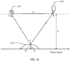
- a third manner of determining the height of the to-be-positioned object is as follows:
- a point A is a location of a projection device 1101
- a point B is a location of a camera 1102
- L2 is a distance between the camera 1102 and the projection device 1101.
- the camera 1102 and the projection device 1101 are installed on a same plane parallel to the target region.
- a height difference between a horizontal plane on which the camera 1102 and the projection device 1101 are located and a horizontal plane of the target region is L.
- the positioning engine obtains a location of a projected point E that is in the target region and onto which the projection device 1101 projects target light.
- the target light is one of a plurality of beams of light projected by the projection device 1101.
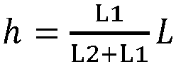
- the target light is reflected at a point C on a surface of the to-be-positioned object 1103, a specified location D is a location of a virtual image generated by reflected light after the reflected light enters the camera 1102, and a height from the to-be-positioned object 1103 to the point C on the surface of the object is h.
- L 1 L 2 h L ⁇ h
- L1 is a distance between the point D and the point E
- L2 is the distance between the point A and the point B.
- the positioning engine may substitute the detected L1, L2, and L into the fifth formula, so that the positioning engine can obtain the height h of the to-be-positioned object.
- the positioning engine can determine a width of each sub-region projected by the projection device onto the target region.
- the camera may simultaneously photograph the to-be-positioned object and a marker that are located in the target region. If the positioning engine has stored a size of the marker, the positioning engine may determine the width of each sub-region based on the size of the marker and a relative location of the marker in the target region. For example, if the positioning engine determines that the marker has a length of 1 meter, and the marker occupies two sub-regions, it indicates that the width of each sub-region is 0.5 meter.
- the positioning engine when the positioning engine, the projection device, and the camera cooperate with each other, the to-be-positioned object can be accurately positioned, and the to-be-positioned object can be positioned, provided that data is exchanged between the positioning engine, the camera, and the projection device. Therefore, dependence on the environment is low.
- the positioning engine can flexibly adjust the first optical pattern based on the environment, and the positioning engine can control the projection device to project first optical patterns with different sizes onto the target region. Therefore, different accuracy requirements for positioning the to-be-positioned object are satisfied.
- the specific process of correcting the first optical pattern projected by the projection device onto the target region is described based on FIG. 2 .
- the following describes, with reference to an embodiment shown in FIG. 12 , a specific process of quickly position the to-be-positioned object.
- Step 1201 The camera collects a second picture and sends the second picture to the positioning engine.
- Step 1202 The positioning engine receives the second picture.
- step 1201 and step 1202 in this embodiment For details about a specific execution process of step 1201 and step 1202 in this embodiment, refer to step 501 and step 502 in FIG. 5 . The specific execution process is not described in this embodiment again.
- Step 1203 The positioning engine determines a target sub-region in which the to-be-positioned object is located in the first optical pattern, where the target sub-region is a sub-region that is in a plurality of sub-regions in the first optical pattern and in which the to-be-positioned object is located.
- the target sub-region is a sub-region that is in the plurality of sub-regions in the first optical pattern and in which a target locating point of the to-be-positioned object is located.
- the target sub-region is the sub-region that is in the plurality of sub-regions in the first optical pattern and in which the target locating point of the to-be-positioned object is located.
- the positioning engine may determine that the to-be-positioned object 1304 is located in a sub-region 1303 in a plurality of sub-regions in the first optical pattern 1300.
- the sub-region 1303 is the target sub-region.
- Step 1204 The positioning engine controls the projection device to project a second optical pattern onto the target sub-region 1303.
- the positioning engine may send a projection instruction to the projection device.
- the projection instruction is used to instruct the projection device to project the second optical pattern onto the target sub-region 1303.
- the second optical pattern also includes a plurality of sub-regions, and an area of the sub-region included in the second optical pattern is less than an area of the sub-region included in the first optical pattern.
- the projection instruction is used to instruct the projection device to project the second optical pattern onto the target sub-region 1303.
- the area of the sub-region in the second optical pattern is less than the area of the sub-region included in the first optical pattern.
- the positioning engine determines that an area of a sub-region 1302 included in the first optical pattern is 1 m x 1 m.
- the positioning engine may project the second optical pattern in the target sub-region 1303.
- the second optical pattern includes a plurality of sub-regions with an area of 10 cm x 10 cm.
- the positioning engine in this embodiment may alternatively project optical patterns including a plurality of sub-regions with an area of 10 cm x 10 cm onto the target sub-region 1303 and a sub-region surrounding the target sub-region 1303.
- 10 sub-regions 1401 may be projected in the target sub-region 1303, and positioning accuracy of the to-be-positioned object changes from 1 m to 10 cm. Therefore, the positioning accuracy of the to-be-positioned object is improved.
- Step 1205 The positioning engine determines a target sub-region in which the to-be-positioned object is located in the second optical pattern, where the target sub-region is a sub-region that is in the plurality of sub-regions in the second optical pattern and in which the to-be-positioned object is located.
- the positioning engine when the positioning engine has projected the second optical pattern onto the target sub-region 1303, the target sub-region 1303 in the second optical pattern is divided into a plurality of smaller sub-regions.
- the positioning engine may further determine a sub-region that is in the plurality of sub-regions in the second optical pattern and in which the to-be-positioned object is located.
- Step 1206 The positioning engine determines a location of the to-be-positioned object in the target region based on a location of the target sub-region, determined in step 1205, in the second optical pattern.
- positioning accuracy of the to-be-positioned object can be further improved, and the to-be-positioned object can be roughly positioned by using the first optical pattern in this embodiment.
- the positioning engine may control the projection device to project the finer second optical pattern onto the target sub-region in the first optical pattern, to avoid projecting the second optical pattern with relatively high accuracy onto the entire target region. This can implement more accurate positioning, avoid complexity of positioning the to-be-positioned object, and improve efficiency of positioning the to-be-positioned object.
- the disclosed system, apparatus, and method may be implemented in other manners.
- the described apparatus embodiment is merely an example.
- the unit division is merely logical function division and may be other division in actual implementation.
- a plurality of units or components may be combined or integrated into another system, or some features may be ignored or not performed.
- the displayed or discussed mutual couplings or direct couplings or communication connections may be implemented by using some interfaces.
- the indirect couplings or communication connections between the apparatuses or units may be implemented in electronic, mechanical, or other forms.
- the units described as separate parts may or may not be physically separate, and parts displayed as units may or may not be physical units, may be located in one position, or may be distributed on a plurality of network units. Some or all of the units may be selected based on actual requirements to achieve the objectives of the solutions of the embodiments.
- functional units in the embodiments of the present invention may be integrated into one processing unit, or each of the units may exist alone physically, or two or more units are integrated into one unit.
- the integrated unit may be implemented in a form of hardware, or may be implemented in a form of a software functional unit.
- the integrated unit When the integrated unit is implemented in the form of a software functional unit and sold or used as an independent product, the integrated unit may be stored in a computer-readable storage medium. Based on such an understanding, the technical solutions of the present invention essentially, or the part contributing to the prior art, or all or some of the technical solutions may be implemented in the form of a software product.
- the computer software product is stored in a storage medium and includes one or more instructions for instructing a computer device (which may be a personal computer, a server, a network device, or the like) to perform all or some of the steps of the methods described in the embodiments of the present invention.
- the foregoing storage medium includes any medium that can store program code, such as a USB flash drive, a removable hard disk, a read-only memory (Read-Only Memory, ROM), a random access memory (Random Access Memory, RAM), a magnetic disk, or an optical disc.
- program code such as a USB flash drive, a removable hard disk, a read-only memory (Read-Only Memory, ROM), a random access memory (Random Access Memory, RAM), a magnetic disk, or an optical disc.
Landscapes
- Engineering & Computer Science (AREA)
- Radar, Positioning & Navigation (AREA)
- Remote Sensing (AREA)
- Physics & Mathematics (AREA)
- General Physics & Mathematics (AREA)
- Electromagnetism (AREA)
- Automation & Control Theory (AREA)
- Multimedia (AREA)
- Computer Vision & Pattern Recognition (AREA)
- Theoretical Computer Science (AREA)
- Computer Networks & Wireless Communication (AREA)
- Length Measuring Devices By Optical Means (AREA)
- Projection Apparatus (AREA)
Claims (13)
- Positionierungssystem, das mindestens eine Projektionsvorrichtung (102), mindestens eine Kamera (103) und eine Positionierungsmaschine (101) umfasst, wobei die Positionierungsmaschine (101) mit einer der mindestens einen Projektionsvorrichtung (102) verbunden ist und die Positionierungsmaschine (101) ferner mit einer der mindestens einen Kamera (103) verbunden ist;die mindestens eine Projektionsvorrichtung (102) dazu konfiguriert ist, ein erstes optisches Muster (100) auf eine Zielregion zu projizieren, wobei das erste optische Muster (100) eine Vielzahl von Unterregionen umfasst;die mindestens eine Kamera (103) dazu konfiguriert ist, ein zweites Bild zu sammeln und das zweite Bild an die Positionierungsmaschine (101) zu senden, wobei das zweite Bild das erste optische Muster (100) sowie ein Objekt, dessen Position zu bestimmen ist und das sich im ersten optischen Muster (100) befindet, umfasst; unddie Positionierungsmaschine (101) dazu konfiguriert ist, das zweite Bild zu empfangen und basierend auf einem Standort des Objekts, dessen Position zu bestimmen ist, im ersten optischen Muster (100) im zweiten Bild einen Standort des Objekts, dessen Position zu bestimmen ist, in der Zielregion zu bestimmen; und die mindestens eine Kamera (103) ferner dazu konfiguriert ist, ein erstes Bild zu sammeln und das erste Bild an die Positionierungsmaschine (101) zu senden, wobei das erste Bild das erste optische Muster (100) umfasst, das von der mindestens einen Projektionsvorrichtung (102) auf die Zielregion projiziert wird; unddie Positionierungsmaschine (101) ferner dazu konfiguriert ist, das erste Bild zu empfangen und die Zielregion basierend auf dem ersten Bild zu markieren;dadurch gekennzeichnet, dassdas System zwei Projektionsvorrichtungen (102) umfasst: eine erste Projektionsvorrichtung und eine zweite Projektionsvorrichtung und dass die Positionierungsmaschine (101) die Zielregion basierend auf dem ersten Bild durch Folgendes markiert:Empfangen von zwei ersten Bildern, wobei die zwei ersten Bilder von der mindestens einen Kamera gesammelt werden und ein erstes Bild, das das erste optische Muster (100) umfasst, das von der ersten Projektionsvorrichtung auf die Zielregion projiziert wird, und ein erstes Bild, das das erste optische Muster (100) umfasst, das von der zweiten Projektionsvorrichtung auf die Zielregion projiziert wird, sind;Identifizieren der Vielzahl von Unterregionen, die im ersten optischen Muster (100) umfasst sind, in jedem der zwei ersten Bilder undSenden von Anpassungsinformationen an die erste Projektionsvorrichtung und/oder die zweite Projektionsvorrichtung, derart, dass die erste Projektionsvorrichtung und/oder die zweite Projektionsvorrichtung eine Anpassung basierend auf den Anpassungsinformationen vornehmen/vornimmt und Unterregionen in den ersten optischen Mustern (100) in den zwei ersten Bildern ausgerichtet sind, wobei die Anpassungsinformationen verwendet werden, um eine Ausrichtung der Unterregionen in den ersten optischen Mustern (100) in den zwei ersten Bildern zu steuern.
- System nach Anspruch 1, wobeidie Positionierungsmaschine (101) dazu konfiguriert ist, eine Zielunterregion zu bestimmen, wobei die Zielunterregion eine Unterregion ist, die in der Vielzahl von Unterregionen im ersten optischen Muster (100) enthalten ist und in der sich das Objekt, dessen Position zu bestimmen ist, befindet;die Positionierungsmaschine (101) ferner dazu konfiguriert ist, eine Steuersignalisierung an die mindestens eine Projektionsvorrichtung (102) zu senden, wobei die Steuersignalisierung verwendet wird, um die mindestens eine Projektionsvorrichtung (102) zu steuern, um ein zweites optisches Muster auf die Zielunterregion zu projizieren, das zweite optische Muster eine Vielzahl von Unterregionen umfasst und ein Bereich der Unterregion, die im zweiten optischen Muster umfasst ist, kleiner ist als ein Bereich der Unterregion, die im ersten optischen Muster umfasst ist; unddie mindestens eine Projektionsvorrichtung (102) dazu konfiguriert ist, die Steuersignalisierung zu empfangen und das zweite optische Muster basierend auf der Steuersignalisierung auf die Zielunterregion zu projizieren.
- System nach Anspruch 2, wobei das zweite Bild ferner das zweite optische Muster sowie das Objekt umfasst, dessen Position zu bestimmen ist und das sich im zweiten optischen Muster befindet; und
die Positionierungsmaschine (101) ist ferner dazu konfiguriert, den Standort des Objekts, dessen Position zu bestimmen ist, basierend auf einem Standort des Objekts, dessen Position zu bestimmen ist, im zweiten optischen Muster im zweiten Bild in der Zielregion zu bestimmen. - System nach Anspruch 1, wobei
die Positionierungsmaschine (101) ferner zu Folgendem konfiguriert ist: Erhalten einer Breite einer Zielunterregion, wobei die Zielunterregion eine Unterregion ist, die in einer Vielzahl von Unterregionen enthalten ist, die in einem optischen Zielmuster umfasst sind, und in der sich das Objekt, dessen Position zu bestimmen ist, befindet, das optische Zielmuster das erste optische Muster oder das zweite optische Muster ist und der Bereich der Unterregion, der im zweiten optischen Muster umfasst ist, kleiner ist als der Bereich der Unterregion, die im ersten optischen Muster umfasst ist; und Bestimmen des Standorts des Objekts, dessen Position zu bestimmen ist, in der Zielregion basierend auf einem Standort der Zielunterregion im zweiten Bild und der Breite der Zielunterregion. - System nach Anspruch 1, wobeidie mindestens eine Kamera (103) ferner dazu konfiguriert ist, Höheninformationen zu sammeln, wobei die Höheninformationen verwendet werden, um eine Höhe des Objekts, dessen Position zu bestimmen ist, in der Zielregion anzuzeigen; unddie Positionierungsmaschine (101) ferner dazu konfiguriert ist, die Höheninformationen, die von der mindestens einen Kamera (103) gesammelt werden, zu erhalten.
- System nach Anspruch 2, wobei
die Positionierungsmaschine (101) ferner zu Folgendem konfiguriert ist: Erhalten der Breite d2 der Zielunterregion, wobei die Zielunterregion die Unterregion ist, die in der Vielzahl von Unterregionen enthalten ist, die im optischen Zielmuster umfasst sind, und in der sich das Objekt, dessen Position zu bestimmen ist, befindet, wobei das optische Zielmuster das erste optische Muster (100) oder das zweite optische Muster ist und der Bereich der Unterregion, der im zweiten optischen Muster umfasst ist, kleiner ist als der Bereich der Unterregion, die im ersten optischen Muster (100) umfasst ist; wenn sich das Objekt, dessen Position zu bestimmen ist, im optischen Zielmuster befindet, Erhalten einer Breite d1 einer Unterregion, die von der mindestens einen Projektionsvorrichtung auf eine Fläche des Objekts, dessen Position zu bestimmen ist, projiziert wird; und Erhalten einer Höhe h des Objekts, dessen Position zu bestimmen ist, in der Region gemäß einer Formel h = (1-d 1/d 2) L, wobei L ein Abstand von der Zielregion zu der mindestens einen Projektionsvorrichtung (102) ist. - System nach Anspruch 1, wobeidie mindestens eine Projektionsvorrichtung (102) ferner dazu konfiguriert ist, Ziellicht zu projizieren, wobei das Ziellicht einer von einer Vielzahl von Lichtstrahlen ist, die von der mindestens einen Projektionsvorrichtung (102) projiziert werden; unddie Positionierungsmaschine (101) ferner dazu konfiguriert ist, einen Standort eines projizierten Punkts zu erhalten, der sich in der Zielregion befindet und auf den das Ziellicht projiziert ist; und wenn sich das Objekt, dessen Standort zu lokalisieren ist, im optischen Zielmuster befindet, das optische Zielmuster das erste optische Muster oder das zweite optische Muster ist und der Bereich der Unterregion, der im zweiten optischen Muster umfasst ist, kleiner ist als der Bereich der Unterregion, die im ersten optischen Muster umfasst ist, die Positionierungsmaschine zu Folgendem konfiguriert ist: Erhalten eines spezifizierten Standorts, wobei der spezifizierte Standort ein Standort eines virtuellen Bildes ist, das von reflektiertem Licht im optischen Zielmuster erzeugt wird, nachdem das reflektierte Licht in eine der mindestens einen Kamera (103) eingetreten ist, und das reflektierte Licht Licht ist, das durch Reflektieren des Ziellichts von einer Fläche des Objekts, dessen Position zu bestimmen ist, erzeugt wird; und Erhalten einer Höhe h des Objekts, dessen Position zu bestimmen ist, in der Zielregion gemäß einer Formel

- Positionierungsverfahren, das Folgendes umfasst:Erhalten (203) eines ersten Bildes, das von mindestens einer Kamera (103) gesammelt wird, wobei das erste Bild ein erstes optisches Muster (100) umfasst, das von mindestens einer Projektionsvorrichtung (102) auf eine Zielregion projiziert wird, und das erste optische Muster (100) eine Vielzahl von Unterregionen umfasst; undMarkieren der Zielregion basierend auf dem ersten Bild;Erhalten eines zweiten Bildes, das von der mindestens einen Kamera (103) gesammelt wird, wobei das zweite Bild das erste optische Muster (100) umfasst, das von der mindestens einen Projektionsvorrichtung (102) auf die Zielregion und ein Objekt, dessen Position zu bestimmen ist und das sich im ersten optischen Muster (100) befindet, projiziert wird; undBestimmen eines Standorts des Objekts, dessen Position zu bestimmen ist, in der Zielregion basierend auf einem Standort des Objekts, dessen Position zu bestimmen ist, im ersten optischen Muster im zweiten Bild;dadurch gekennzeichnet, dassdas Markieren der Zielregion basierend auf dem ersten Bild Folgendes umfasst:Empfangen von zwei ersten Bildern, wobei die zwei ersten Bilder von der mindestens einen Kamera (103) gesammelt werden und ein erstes Bild, das das erste optische Muster (100) umfasst, das von einer ersten Projektionsvorrichtung auf die Zielregion projiziert wird, und ein erstes Bild, das das erste optische Muster (100) umfasst, das von einer zweiten Projektionsvorrichtung auf die Zielregion projiziert wird, sind;Identifizieren der Vielzahl von Unterregionen, die im ersten optischen Muster (100) umfasst sind, in jedem der zwei ersten Bilder; undSenden (207) von Anpassungsinformationen an die erste Projektionsvorrichtung und/oder die zweite Projektionsvorrichtung, derart, dass die erste Projektionsvorrichtung und/oder die zweite Projektionsvorrichtung eine Anpassung basierend auf den Anpassungsinformationen vornehmen/vornimmt, und Unterregionen in den ersten optischen Mustern (100) in den zwei ersten Bildern ausgerichtet sind, wobei die Anpassungsinformationen verwendet werden, um eine Ausrichtung der Unterregionen in den ersten optischen Mustern (100) in den zwei ersten Bildern zu steuern.
- Verfahren nach Anspruch 8, wobei das Verfahren ferner Folgendes umfasst:Bestimmen (1203) einer Zielunterregion, wobei die Zielunterregion eine Unterregion ist, die in der Vielzahl von Unterregionen im ersten optischen Muster (100) enthalten ist und in der sich das Objekt, dessen Position zu bestimmen ist, befindet; undSenden (1204) einer Steuersignalisierung an die mindestens eine Projektionsvorrichtung (102), wobei die Steuersignalisierung verwendet wird, um die mindestens eine Projektionsvorrichtung (102) zu steuern, um ein zweites optisches Muster auf die Zielunterregion zu projizieren, das zweite optische Muster eine Vielzahl von Unterregionen umfasst und ein Bereich der Unterregion, die im zweiten optischen Muster umfasst ist, kleiner ist als ein Bereich der Unterregion, die im ersten optischen Muster umfasst ist.
- Verfahren nach Anspruch 8,
wobei das Bestimmen (1203) eines Standorts des Objekts, dessen Position zu bestimmen ist, in der Zielregion basierend auf einem Standort des Objekts, dessen Position zu bestimmen ist, im ersten optischen Muster im zweiten Bild Folgendes umfasst:Bestimmen des Standorts des Objekts, dessen Position zu bestimmen ist, basierend auf einem Standort des Objekts, dessen Position zu bestimmen ist, im zweiten optischen Muster im zweiten Bild in der Zielregion undwobei das Bestimmen eines Standorts des Objekts, dessen Position zu bestimmen ist, in der Zielregion basierend auf einem Standort des Objekts, dessen Position zu bestimmen ist, im ersten optischen Muster im zweiten Bild Folgendes umfasst:Erhalten einer Breite einer Zielunterregion, wobei die Zielunterregion eine Unterregion ist, die in einer Vielzahl von Unterregionen enthalten ist, die in einem optischen Zielmuster umfasst sind, und in der sich das Objekt, dessen Position zu bestimmen ist, befindet, das optische Zielmuster das erste optische Muster (100) oder das zweite optische Muster ist und der Bereich der Unterregion, der im zweiten optischen Muster umfasst ist, kleiner ist als der Bereich der Unterregion, die im ersten optischen Muster (100) umfasst ist; undBestimmen des Standorts des Objekts, dessen Position zu bestimmen ist, in er Zielregion basierend auf einem Standort der Zielunterregion im zweiten Bild und der Breite der Zielunterregion. - Verfahren nach Anspruch 8, wobei das Verfahren ferner Folgendes umfasst:
Erhalten von Höheninformationen, die von der mindestens einen Kamera (103) gesammelt werden, wobei die Höheninformationen verwendet werden, um eine Höhe des Objekts, dessen Position zu bestimmen ist, in der Zielregion anzuzeigen. - Verfahren nach Anspruch 9, wobei das Bestimmen des Standorts des Objekts, dessen Position zu bestimmen ist, in der Zielregion basierend auf einem Standort der Zielunterregion im zweiten Bild und der Breite der Zielunterregion Folgendes umfasst:Erhalten der Breite d2 der Zielunterregion, wobei die Zielunterregion die Unterregion ist, die in der Vielzahl von Unterregionen enthalten ist, die im optischen Zielmuster umfasst sind, und in der sich das Objekt, dessen Position zu bestimmen ist, befindet, wobei das optische Zielmuster das erste optische Muster oder das zweite optische Muster ist und der Bereich der Unterregion, der im zweiten optischen Muster umfasst ist, kleiner ist als der Bereich der Unterregion, die im ersten optischen Muster umfasst ist;wenn sich das Objekt, dessen Position zu bestimmen ist, im optischen Zielmuster befindet, Erhalten einer Breite d1 einer Unterregion, die von mindestens einer Projektionsvorrichtung auf eine Fläche des Objekts, dessen Position zu bestimmen ist, projiziert wird; undErhalten einer Höhe h des Objekts, dessen Position zu bestimmen ist, in der Zielregion gemäß einer Formel h = (1-d 1/d 2) L, wobei L ein Abstand von der Zielregion zu der mindestens einen Projektionsvorrichtung (102) ist.
- Verfahren nach Anspruch 8, wobei das Bestimmen des Standorts des Objekts, dessen Position zu bestimmen ist, in der Zielregion basierend auf einem Standort der Zielunterregion im zweiten Bild und der Breite der Zielunterregion Folgendes umfasst:Erhalten eines Standorts eines projizierten Punkts, auf den die mindestens eine Projektionsvorrichtung Ziellicht projiziert, in der Zielregion, wobei das Ziellicht einer von einer Vielzahl von Lichtstrahlen ist, die von der mindestens einen Projektionsvorrichtung (102) projiziert werden;wenn sich das Objekt, dessen Position zu bestimmen ist, im optischen Zielmuster befindet, das optische Zielmuster das erste optische Muster (100) oder das zweite optische Muster ist undder Bereich der Unterregion, der im zweiten optischen Muster umfasst ist, kleiner ist als der Bereich der Unterregion, die im ersten optischen Muster (100) umfasst ist, Erhalten eines spezifizierten Standorts, wobei der spezifizierte Standort ein Standort eines virtuellen Bildes ist, das von reflektiertem Licht im optischen Zielmuster erzeugt wird, nachdem das reflektierte Licht in eine der mindestens einen Kamera (103) eingetreten ist, und das reflektierte Licht Licht ist, das durch Reflektieren des Ziellichts von einer Fläche des Objekts, dessen Position zu bestimmen ist, erzeugt wird; undErhalten einer Höhe h des Objekts, dessen Position zu bestimmen ist, in der Zielregion gemäß einer Formel
 der Kamera (103) ist, die sich auf einer selben horizontalen Ebene befinden und L ein Abstand von der Zielregion zu der mindestens einen Projektionsvorrichtung (102) ist.
Applications Claiming Priority (2)
| Application Number | Priority Date | Filing Date | Title |
|---|---|---|---|
| CN201710640551.8A CN109323691B (zh) | 2017-07-31 | 2017-07-31 | 一种定位系统以及定位方法 |
| PCT/CN2018/077742 WO2019024498A1 (zh) | 2017-07-31 | 2018-03-01 | 一种定位系统以及定位方法 |
Publications (3)
| Publication Number | Publication Date |
|---|---|
| EP3660452A1 EP3660452A1 (de) | 2020-06-03 |
| EP3660452A4 EP3660452A4 (de) | 2020-11-25 |
| EP3660452B1 true EP3660452B1 (de) | 2022-07-27 |
Family
ID=65232811
Family Applications (1)
| Application Number | Title | Priority Date | Filing Date |
|---|---|---|---|
| EP18841158.1A Active EP3660452B1 (de) | 2017-07-31 | 2018-03-01 | Positionierungssystem und positionierungsverfahren |
Country Status (3)
| Country | Link |
|---|---|
| EP (1) | EP3660452B1 (de) |
| CN (1) | CN109323691B (de) |
| WO (1) | WO2019024498A1 (de) |
Families Citing this family (2)
| Publication number | Priority date | Publication date | Assignee | Title |
|---|---|---|---|---|
| CN110708524A (zh) * | 2019-04-24 | 2020-01-17 | 广州星博科仪有限公司 | 一种基于光谱成像的目标投影指示装置 |
| DE102021205659B4 (de) | 2021-06-03 | 2023-08-10 | Fraunhofer-Gesellschaft zur Förderung der angewandten Forschung eingetragener Verein | Verfahren zum Prüfen von Bauteiloberflächen auf Fehler und/oder Bestimmen von Eigenschaften von Bauteilbeschichtungen |
Family Cites Families (10)
| Publication number | Priority date | Publication date | Assignee | Title |
|---|---|---|---|---|
| JPH0711420B2 (ja) * | 1990-05-23 | 1995-02-08 | 日本電気株式会社 | 距離画像取得方法及び装置 |
| DE10212364A1 (de) * | 2002-03-20 | 2003-10-16 | Steinbichler Optotechnik Gmbh | Verfahren und Vorrichtung zur Bestimmung der Absolut-Koordinaten eines Objekts |
| WO2008149923A1 (ja) * | 2007-06-07 | 2008-12-11 | The University Of Electro-Communications | 物体検出装置とそれを適用したゲート装置 |
| CN101661098B (zh) * | 2009-09-10 | 2011-07-27 | 上海交通大学 | 机器人餐厅多机器人自动定位系统 |
| US9200899B2 (en) * | 2012-03-22 | 2015-12-01 | Virtek Vision International, Inc. | Laser projection system and method |
| CN106461378B (zh) * | 2014-08-08 | 2019-10-25 | 塞姆布有限公司 | 具有用于非接触式测量的扫描系统的车辆装备 |
| US9857167B2 (en) * | 2015-06-23 | 2018-01-02 | Hand Held Products, Inc. | Dual-projector three-dimensional scanner |
| CN205909828U (zh) * | 2016-08-06 | 2017-01-25 | 中科院合肥技术创新工程院 | 一种用于室内移动机器人定位的红外路标 |
| CN106403941B (zh) * | 2016-08-29 | 2019-04-19 | 上海智臻智能网络科技股份有限公司 | 一种定位方法及装置 |
| CN106781476B (zh) * | 2016-12-22 | 2019-08-20 | 中国人民解放军第三军医大学第三附属医院 | 交通事故中车辆动态位置分析方法 |
-
2017
- 2017-07-31 CN CN201710640551.8A patent/CN109323691B/zh active Active
-
2018
- 2018-03-01 EP EP18841158.1A patent/EP3660452B1/de active Active
- 2018-03-01 WO PCT/CN2018/077742 patent/WO2019024498A1/zh not_active Ceased
Also Published As
| Publication number | Publication date |
|---|---|
| CN109323691A (zh) | 2019-02-12 |
| EP3660452A1 (de) | 2020-06-03 |
| EP3660452A4 (de) | 2020-11-25 |
| WO2019024498A1 (zh) | 2019-02-07 |
| CN109323691B (zh) | 2022-08-09 |
Similar Documents
| Publication | Publication Date | Title |
|---|---|---|
| CN111179358B (zh) | 标定方法、装置、设备及存储介质 | |
| JP6363863B2 (ja) | 情報処理装置および情報処理方法 | |
| EP3771198B1 (de) | Verfahren und vorrichtung zur zielverfolgung, bewegliche plattform und speichermedium | |
| JP7480882B2 (ja) | 情報処理装置、認識支援方法およびコンピュータプログラム | |
| JP6352208B2 (ja) | 三次元モデル処理装置およびカメラ校正システム | |
| JP6260891B2 (ja) | 画像処理装置および画像処理方法 | |
| JP2012215394A (ja) | 三次元計測装置および三次元計測方法 | |
| CN110753167B (zh) | 时间同步方法、装置、终端设备及存储介质 | |
| CN108509173A (zh) | 图像展示系统及方法、存储介质、处理器 | |
| CN110111394A (zh) | 基于机械手特征对摄像机自动标定的方法及装置 | |
| CN110880161B (zh) | 一种多主机多深度摄像头的深度图像拼接融合方法及系统 | |
| EP3660452B1 (de) | Positionierungssystem und positionierungsverfahren | |
| CN105184768B (zh) | 室内多摄像头同步高精度定位方法 | |
| KR20200042782A (ko) | 입체 모델 생성 장치 및 그 영상 표시 방법 | |
| JP2022067694A (ja) | 作業者管理システム | |
| US20220414916A1 (en) | Systems and methods for assigning a symbol to an object | |
| US12073506B2 (en) | Methods, systems, and media for generating images of multiple sides of an object | |
| JP5502771B2 (ja) | 電子黒板システム及びプログラム | |
| JP6022330B2 (ja) | カメラシステム | |
| JP6022331B2 (ja) | カメラシステム | |
| EP4597422A1 (de) | Vorrichtung, computerprogramm und verfahren | |
| KR102887139B1 (ko) | 전시품의 조명을 위한 전동식 스포트라이트 제어방법 및 장치 | |
| US20250111538A1 (en) | System and method for part profile identification | |
| CN114913505A (zh) | 交通标志识别方法及设备 | |
| CN121033178A (zh) | 基于相机屏幕一体化的外参标定方法及相关装置 |
Legal Events
| Date | Code | Title | Description |
|---|---|---|---|
| STAA | Information on the status of an ep patent application or granted ep patent |
Free format text: STATUS: THE INTERNATIONAL PUBLICATION HAS BEEN MADE |
|
| PUAI | Public reference made under article 153(3) epc to a published international application that has entered the european phase |
Free format text: ORIGINAL CODE: 0009012 |
|
| STAA | Information on the status of an ep patent application or granted ep patent |
Free format text: STATUS: REQUEST FOR EXAMINATION WAS MADE |
|
| 17P | Request for examination filed |
Effective date: 20200225 |
|
| AK | Designated contracting states |
Kind code of ref document: A1 Designated state(s): AL AT BE BG CH CY CZ DE DK EE ES FI FR GB GR HR HU IE IS IT LI LT LU LV MC MK MT NL NO PL PT RO RS SE SI SK SM TR |
|
| AX | Request for extension of the european patent |
Extension state: BA ME |
|
| RIC1 | Information provided on ipc code assigned before grant |
Ipc: G01C 21/00 20060101AFI20200715BHEP Ipc: G06T 7/73 20170101ALI20200715BHEP Ipc: G01B 11/00 20060101ALI20200715BHEP Ipc: G01B 11/25 20060101ALI20200715BHEP Ipc: G01C 11/02 20060101ALI20200715BHEP Ipc: G01C 21/20 20060101ALI20200715BHEP |
|
| DAV | Request for validation of the european patent (deleted) | ||
| DAX | Request for extension of the european patent (deleted) | ||
| RIC1 | Information provided on ipc code assigned before grant |
Ipc: G06T 7/73 20170101ALI20201015BHEP Ipc: G01B 11/00 20060101ALI20201015BHEP Ipc: G01C 21/00 20060101AFI20201015BHEP Ipc: G01C 11/02 20060101ALI20201015BHEP Ipc: G01C 21/20 20060101ALI20201015BHEP Ipc: G01B 11/25 20060101ALI20201015BHEP |
|
| A4 | Supplementary search report drawn up and despatched |
Effective date: 20201023 |
|
| RIC1 | Information provided on ipc code assigned before grant |
Ipc: G01C 11/02 20060101ALI20201019BHEP Ipc: G01B 11/00 20060101ALI20201019BHEP Ipc: G06T 7/73 20170101ALI20201019BHEP Ipc: G01C 21/20 20060101ALI20201019BHEP Ipc: G01C 21/00 20060101AFI20201019BHEP Ipc: G01B 11/25 20060101ALI20201019BHEP |
|
| REG | Reference to a national code |
Ref country code: DE Ref legal event code: R079 Ref document number: 602018038557 Country of ref document: DE Free format text: PREVIOUS MAIN CLASS: G01C0021000000 Ipc: G01C0011020000 |
|
| RIC1 | Information provided on ipc code assigned before grant |
Ipc: G06T 7/73 20170101ALI20220121BHEP Ipc: G01S 17/48 20060101ALI20220121BHEP Ipc: G01C 21/20 20060101ALI20220121BHEP Ipc: G01C 11/02 20060101AFI20220121BHEP |
|
| GRAP | Despatch of communication of intention to grant a patent |
Free format text: ORIGINAL CODE: EPIDOSNIGR1 |
|
| STAA | Information on the status of an ep patent application or granted ep patent |
Free format text: STATUS: GRANT OF PATENT IS INTENDED |
|
| INTG | Intention to grant announced |
Effective date: 20220318 |
|
| GRAS | Grant fee paid |
Free format text: ORIGINAL CODE: EPIDOSNIGR3 |
|
| GRAA | (expected) grant |
Free format text: ORIGINAL CODE: 0009210 |
|
| STAA | Information on the status of an ep patent application or granted ep patent |
Free format text: STATUS: THE PATENT HAS BEEN GRANTED |
|
| AK | Designated contracting states |
Kind code of ref document: B1 Designated state(s): AL AT BE BG CH CY CZ DE DK EE ES FI FR GB GR HR HU IE IS IT LI LT LU LV MC MK MT NL NO PL PT RO RS SE SI SK SM TR |
|
| REG | Reference to a national code |
Ref country code: CH Ref legal event code: EP |
|
| REG | Reference to a national code |
Ref country code: DE Ref legal event code: R096 Ref document number: 602018038557 Country of ref document: DE |
|
| REG | Reference to a national code |
Ref country code: AT Ref legal event code: REF Ref document number: 1507331 Country of ref document: AT Kind code of ref document: T Effective date: 20220815 |
|
| REG | Reference to a national code |
Ref country code: NL Ref legal event code: FP |
|
| REG | Reference to a national code |
Ref country code: IE Ref legal event code: FG4D |
|
| REG | Reference to a national code |
Ref country code: LT Ref legal event code: MG9D |
|
| PG25 | Lapsed in a contracting state [announced via postgrant information from national office to epo] |
Ref country code: SE Free format text: LAPSE BECAUSE OF FAILURE TO SUBMIT A TRANSLATION OF THE DESCRIPTION OR TO PAY THE FEE WITHIN THE PRESCRIBED TIME-LIMIT Effective date: 20220727 Ref country code: RS Free format text: LAPSE BECAUSE OF FAILURE TO SUBMIT A TRANSLATION OF THE DESCRIPTION OR TO PAY THE FEE WITHIN THE PRESCRIBED TIME-LIMIT Effective date: 20220727 Ref country code: PT Free format text: LAPSE BECAUSE OF FAILURE TO SUBMIT A TRANSLATION OF THE DESCRIPTION OR TO PAY THE FEE WITHIN THE PRESCRIBED TIME-LIMIT Effective date: 20221128 Ref country code: NO Free format text: LAPSE BECAUSE OF FAILURE TO SUBMIT A TRANSLATION OF THE DESCRIPTION OR TO PAY THE FEE WITHIN THE PRESCRIBED TIME-LIMIT Effective date: 20221027 Ref country code: LV Free format text: LAPSE BECAUSE OF FAILURE TO SUBMIT A TRANSLATION OF THE DESCRIPTION OR TO PAY THE FEE WITHIN THE PRESCRIBED TIME-LIMIT Effective date: 20220727 Ref country code: LT Free format text: LAPSE BECAUSE OF FAILURE TO SUBMIT A TRANSLATION OF THE DESCRIPTION OR TO PAY THE FEE WITHIN THE PRESCRIBED TIME-LIMIT Effective date: 20220727 Ref country code: FI Free format text: LAPSE BECAUSE OF FAILURE TO SUBMIT A TRANSLATION OF THE DESCRIPTION OR TO PAY THE FEE WITHIN THE PRESCRIBED TIME-LIMIT Effective date: 20220727 Ref country code: ES Free format text: LAPSE BECAUSE OF FAILURE TO SUBMIT A TRANSLATION OF THE DESCRIPTION OR TO PAY THE FEE WITHIN THE PRESCRIBED TIME-LIMIT Effective date: 20220727 |
|
| REG | Reference to a national code |
Ref country code: AT Ref legal event code: MK05 Ref document number: 1507331 Country of ref document: AT Kind code of ref document: T Effective date: 20220727 |
|
| PG25 | Lapsed in a contracting state [announced via postgrant information from national office to epo] |
Ref country code: PL Free format text: LAPSE BECAUSE OF FAILURE TO SUBMIT A TRANSLATION OF THE DESCRIPTION OR TO PAY THE FEE WITHIN THE PRESCRIBED TIME-LIMIT Effective date: 20220727 Ref country code: IS Free format text: LAPSE BECAUSE OF FAILURE TO SUBMIT A TRANSLATION OF THE DESCRIPTION OR TO PAY THE FEE WITHIN THE PRESCRIBED TIME-LIMIT Effective date: 20221127 Ref country code: HR Free format text: LAPSE BECAUSE OF FAILURE TO SUBMIT A TRANSLATION OF THE DESCRIPTION OR TO PAY THE FEE WITHIN THE PRESCRIBED TIME-LIMIT Effective date: 20220727 Ref country code: GR Free format text: LAPSE BECAUSE OF FAILURE TO SUBMIT A TRANSLATION OF THE DESCRIPTION OR TO PAY THE FEE WITHIN THE PRESCRIBED TIME-LIMIT Effective date: 20221028 |
|
| PG25 | Lapsed in a contracting state [announced via postgrant information from national office to epo] |
Ref country code: SM Free format text: LAPSE BECAUSE OF FAILURE TO SUBMIT A TRANSLATION OF THE DESCRIPTION OR TO PAY THE FEE WITHIN THE PRESCRIBED TIME-LIMIT Effective date: 20220727 Ref country code: RO Free format text: LAPSE BECAUSE OF FAILURE TO SUBMIT A TRANSLATION OF THE DESCRIPTION OR TO PAY THE FEE WITHIN THE PRESCRIBED TIME-LIMIT Effective date: 20220727 Ref country code: DK Free format text: LAPSE BECAUSE OF FAILURE TO SUBMIT A TRANSLATION OF THE DESCRIPTION OR TO PAY THE FEE WITHIN THE PRESCRIBED TIME-LIMIT Effective date: 20220727 Ref country code: CZ Free format text: LAPSE BECAUSE OF FAILURE TO SUBMIT A TRANSLATION OF THE DESCRIPTION OR TO PAY THE FEE WITHIN THE PRESCRIBED TIME-LIMIT Effective date: 20220727 Ref country code: AT Free format text: LAPSE BECAUSE OF FAILURE TO SUBMIT A TRANSLATION OF THE DESCRIPTION OR TO PAY THE FEE WITHIN THE PRESCRIBED TIME-LIMIT Effective date: 20220727 |
|
| REG | Reference to a national code |
Ref country code: DE Ref legal event code: R097 Ref document number: 602018038557 Country of ref document: DE |
|
| PG25 | Lapsed in a contracting state [announced via postgrant information from national office to epo] |
Ref country code: SK Free format text: LAPSE BECAUSE OF FAILURE TO SUBMIT A TRANSLATION OF THE DESCRIPTION OR TO PAY THE FEE WITHIN THE PRESCRIBED TIME-LIMIT Effective date: 20220727 Ref country code: EE Free format text: LAPSE BECAUSE OF FAILURE TO SUBMIT A TRANSLATION OF THE DESCRIPTION OR TO PAY THE FEE WITHIN THE PRESCRIBED TIME-LIMIT Effective date: 20220727 |
|
| PLBE | No opposition filed within time limit |
Free format text: ORIGINAL CODE: 0009261 |
|
| STAA | Information on the status of an ep patent application or granted ep patent |
Free format text: STATUS: NO OPPOSITION FILED WITHIN TIME LIMIT |
|
| PG25 | Lapsed in a contracting state [announced via postgrant information from national office to epo] |
Ref country code: AL Free format text: LAPSE BECAUSE OF FAILURE TO SUBMIT A TRANSLATION OF THE DESCRIPTION OR TO PAY THE FEE WITHIN THE PRESCRIBED TIME-LIMIT Effective date: 20220727 |
|
| 26N | No opposition filed |
Effective date: 20230502 |
|
| PG25 | Lapsed in a contracting state [announced via postgrant information from national office to epo] |
Ref country code: SI Free format text: LAPSE BECAUSE OF FAILURE TO SUBMIT A TRANSLATION OF THE DESCRIPTION OR TO PAY THE FEE WITHIN THE PRESCRIBED TIME-LIMIT Effective date: 20220727 |
|
| PG25 | Lapsed in a contracting state [announced via postgrant information from national office to epo] |
Ref country code: MC Free format text: LAPSE BECAUSE OF FAILURE TO SUBMIT A TRANSLATION OF THE DESCRIPTION OR TO PAY THE FEE WITHIN THE PRESCRIBED TIME-LIMIT Effective date: 20220727 |
|
| REG | Reference to a national code |
Ref country code: CH Ref legal event code: PL |
|
| REG | Reference to a national code |
Ref country code: BE Ref legal event code: MM Effective date: 20230331 |
|
| PG25 | Lapsed in a contracting state [announced via postgrant information from national office to epo] |
Ref country code: LU Free format text: LAPSE BECAUSE OF NON-PAYMENT OF DUE FEES Effective date: 20230301 |
|
| REG | Reference to a national code |
Ref country code: IE Ref legal event code: MM4A |
|
| PG25 | Lapsed in a contracting state [announced via postgrant information from national office to epo] |
Ref country code: LI Free format text: LAPSE BECAUSE OF NON-PAYMENT OF DUE FEES Effective date: 20230331 Ref country code: IE Free format text: LAPSE BECAUSE OF NON-PAYMENT OF DUE FEES Effective date: 20230301 Ref country code: FR Free format text: LAPSE BECAUSE OF NON-PAYMENT OF DUE FEES Effective date: 20230331 Ref country code: CH Free format text: LAPSE BECAUSE OF NON-PAYMENT OF DUE FEES Effective date: 20230331 |
|
| PG25 | Lapsed in a contracting state [announced via postgrant information from national office to epo] |
Ref country code: BE Free format text: LAPSE BECAUSE OF NON-PAYMENT OF DUE FEES Effective date: 20230331 |
|
| PG25 | Lapsed in a contracting state [announced via postgrant information from national office to epo] |
Ref country code: IT Free format text: LAPSE BECAUSE OF FAILURE TO SUBMIT A TRANSLATION OF THE DESCRIPTION OR TO PAY THE FEE WITHIN THE PRESCRIBED TIME-LIMIT Effective date: 20220727 |
|
| PG25 | Lapsed in a contracting state [announced via postgrant information from national office to epo] |
Ref country code: BG Free format text: LAPSE BECAUSE OF FAILURE TO SUBMIT A TRANSLATION OF THE DESCRIPTION OR TO PAY THE FEE WITHIN THE PRESCRIBED TIME-LIMIT Effective date: 20220727 |
|
| PG25 | Lapsed in a contracting state [announced via postgrant information from national office to epo] |
Ref country code: BG Free format text: LAPSE BECAUSE OF FAILURE TO SUBMIT A TRANSLATION OF THE DESCRIPTION OR TO PAY THE FEE WITHIN THE PRESCRIBED TIME-LIMIT Effective date: 20220727 |
|
| PG25 | Lapsed in a contracting state [announced via postgrant information from national office to epo] |
Ref country code: CY Free format text: LAPSE BECAUSE OF FAILURE TO SUBMIT A TRANSLATION OF THE DESCRIPTION OR TO PAY THE FEE WITHIN THE PRESCRIBED TIME-LIMIT; INVALID AB INITIO Effective date: 20180301 |
|
| PG25 | Lapsed in a contracting state [announced via postgrant information from national office to epo] |
Ref country code: HU Free format text: LAPSE BECAUSE OF FAILURE TO SUBMIT A TRANSLATION OF THE DESCRIPTION OR TO PAY THE FEE WITHIN THE PRESCRIBED TIME-LIMIT; INVALID AB INITIO Effective date: 20180301 |
|
| PG25 | Lapsed in a contracting state [announced via postgrant information from national office to epo] |
Ref country code: TR Free format text: LAPSE BECAUSE OF FAILURE TO SUBMIT A TRANSLATION OF THE DESCRIPTION OR TO PAY THE FEE WITHIN THE PRESCRIBED TIME-LIMIT Effective date: 20220727 |
|
| PGFP | Annual fee paid to national office [announced via postgrant information from national office to epo] |
Ref country code: NL Payment date: 20260213 Year of fee payment: 9 |
|
| PGFP | Annual fee paid to national office [announced via postgrant information from national office to epo] |
Ref country code: GB Payment date: 20260202 Year of fee payment: 9 |
|
| PGFP | Annual fee paid to national office [announced via postgrant information from national office to epo] |
Ref country code: DE Payment date: 20260204 Year of fee payment: 9 |