EP3660572A1 - Dispositif d'observation d'échantillon et procédé d'observation d'échantillon - Google Patents
Dispositif d'observation d'échantillon et procédé d'observation d'échantillon Download PDFInfo
- Publication number
- EP3660572A1 EP3660572A1 EP18839164.3A EP18839164A EP3660572A1 EP 3660572 A1 EP3660572 A1 EP 3660572A1 EP 18839164 A EP18839164 A EP 18839164A EP 3660572 A1 EP3660572 A1 EP 3660572A1
- Authority
- EP
- European Patent Office
- Prior art keywords
- light
- sample
- optical element
- observation
- image
- Prior art date
- Legal status (The legal status is an assumption and is not a legal conclusion. Google has not performed a legal analysis and makes no representation as to the accuracy of the status listed.)
- Granted
Links
Images







Classifications
-
- G—PHYSICS
- G01—MEASURING; TESTING
- G01N—INVESTIGATING OR ANALYSING MATERIALS BY DETERMINING THEIR CHEMICAL OR PHYSICAL PROPERTIES
- G01N21/00—Investigating or analysing materials by the use of optical means, i.e. using sub-millimetre waves, infrared, visible or ultraviolet light
- G01N21/17—Systems in which incident light is modified in accordance with the properties of the material investigated
- G01N21/47—Scattering, i.e. diffuse reflection
- G01N21/49—Scattering, i.e. diffuse reflection within a body or fluid
- G01N21/51—Scattering, i.e. diffuse reflection within a body or fluid inside a container, e.g. in an ampoule
-
- G—PHYSICS
- G02—OPTICS
- G02B—OPTICAL ELEMENTS, SYSTEMS OR APPARATUS
- G02B21/00—Microscopes
- G02B21/0004—Microscopes specially adapted for specific applications
- G02B21/002—Scanning microscopes
- G02B21/0024—Confocal scanning microscopes (CSOMs) or confocal "macroscopes"; Accessories which are not restricted to use with CSOMs, e.g. sample holders
- G02B21/0032—Optical details of illumination, e.g. light-sources, pinholes, beam splitters, slits, fibers
-
- G—PHYSICS
- G01—MEASURING; TESTING
- G01N—INVESTIGATING OR ANALYSING MATERIALS BY DETERMINING THEIR CHEMICAL OR PHYSICAL PROPERTIES
- G01N1/00—Sampling; Preparing specimens for investigation
- G01N1/02—Devices for withdrawing samples
- G01N1/10—Devices for withdrawing samples in the liquid or fluent state
- G01N1/20—Devices for withdrawing samples in the liquid or fluent state for flowing or falling materials
- G01N1/2035—Devices for withdrawing samples in the liquid or fluent state for flowing or falling materials by deviating part of a fluid stream, e.g. by drawing-off or tapping
-
- G—PHYSICS
- G01—MEASURING; TESTING
- G01N—INVESTIGATING OR ANALYSING MATERIALS BY DETERMINING THEIR CHEMICAL OR PHYSICAL PROPERTIES
- G01N15/00—Investigating characteristics of particles; Investigating permeability, pore-volume or surface-area of porous materials
- G01N15/10—Investigating individual particles
- G01N15/14—Optical investigation techniques, e.g. flow cytometry
- G01N15/1434—Optical arrangements
-
- G—PHYSICS
- G01—MEASURING; TESTING
- G01N—INVESTIGATING OR ANALYSING MATERIALS BY DETERMINING THEIR CHEMICAL OR PHYSICAL PROPERTIES
- G01N15/00—Investigating characteristics of particles; Investigating permeability, pore-volume or surface-area of porous materials
- G01N15/10—Investigating individual particles
- G01N15/14—Optical investigation techniques, e.g. flow cytometry
- G01N15/1468—Optical investigation techniques, e.g. flow cytometry with spatial resolution of the texture or inner structure of the particle
- G01N15/147—Optical investigation techniques, e.g. flow cytometry with spatial resolution of the texture or inner structure of the particle the analysis being performed on a sample stream
-
- G—PHYSICS
- G01—MEASURING; TESTING
- G01N—INVESTIGATING OR ANALYSING MATERIALS BY DETERMINING THEIR CHEMICAL OR PHYSICAL PROPERTIES
- G01N21/00—Investigating or analysing materials by the use of optical means, i.e. using sub-millimetre waves, infrared, visible or ultraviolet light
- G01N21/17—Systems in which incident light is modified in accordance with the properties of the material investigated
- G01N21/47—Scattering, i.e. diffuse reflection
- G01N21/49—Scattering, i.e. diffuse reflection within a body or fluid
- G01N21/53—Scattering, i.e. diffuse reflection within a body or fluid within a flowing fluid, e.g. smoke
- G01N21/534—Scattering, i.e. diffuse reflection within a body or fluid within a flowing fluid, e.g. smoke by measuring transmission alone, i.e. determining opacity
-
- G—PHYSICS
- G02—OPTICS
- G02B—OPTICAL ELEMENTS, SYSTEMS OR APPARATUS
- G02B21/00—Microscopes
- G02B21/0004—Microscopes specially adapted for specific applications
- G02B21/002—Scanning microscopes
- G02B21/0024—Confocal scanning microscopes (CSOMs) or confocal "macroscopes"; Accessories which are not restricted to use with CSOMs, e.g. sample holders
- G02B21/0052—Optical details of the image generation
- G02B21/0076—Optical details of the image generation arrangements using fluorescence or luminescence
-
- G—PHYSICS
- G02—OPTICS
- G02B—OPTICAL ELEMENTS, SYSTEMS OR APPARATUS
- G02B21/00—Microscopes
- G02B21/16—Microscopes adapted for ultraviolet illumination ; Fluorescence microscopes
-
- G—PHYSICS
- G02—OPTICS
- G02B—OPTICAL ELEMENTS, SYSTEMS OR APPARATUS
- G02B21/00—Microscopes
- G02B21/36—Microscopes arranged for photographic purposes or projection purposes or digital imaging or video purposes including associated control and data processing arrangements
- G02B21/361—Optical details, e.g. image relay to the camera or image sensor
-
- G—PHYSICS
- G02—OPTICS
- G02B—OPTICAL ELEMENTS, SYSTEMS OR APPARATUS
- G02B21/00—Microscopes
- G02B21/36—Microscopes arranged for photographic purposes or projection purposes or digital imaging or video purposes including associated control and data processing arrangements
- G02B21/365—Control or image processing arrangements for digital or video microscopes
- G02B21/367—Control or image processing arrangements for digital or video microscopes providing an output produced by processing a plurality of individual source images, e.g. image tiling, montage, composite images, depth sectioning, image comparison
-
- G—PHYSICS
- G02—OPTICS
- G02B—OPTICAL ELEMENTS, SYSTEMS OR APPARATUS
- G02B5/00—Optical elements other than lenses
- G02B5/04—Prisms
-
- G—PHYSICS
- G01—MEASURING; TESTING
- G01N—INVESTIGATING OR ANALYSING MATERIALS BY DETERMINING THEIR CHEMICAL OR PHYSICAL PROPERTIES
- G01N15/00—Investigating characteristics of particles; Investigating permeability, pore-volume or surface-area of porous materials
- G01N15/10—Investigating individual particles
- G01N2015/1006—Investigating individual particles for cytology
-
- G—PHYSICS
- G01—MEASURING; TESTING
- G01N—INVESTIGATING OR ANALYSING MATERIALS BY DETERMINING THEIR CHEMICAL OR PHYSICAL PROPERTIES
- G01N15/00—Investigating characteristics of particles; Investigating permeability, pore-volume or surface-area of porous materials
- G01N15/10—Investigating individual particles
- G01N15/14—Optical investigation techniques, e.g. flow cytometry
- G01N15/1434—Optical arrangements
- G01N2015/144—Imaging characterised by its optical setup
-
- G—PHYSICS
- G01—MEASURING; TESTING
- G01N—INVESTIGATING OR ANALYSING MATERIALS BY DETERMINING THEIR CHEMICAL OR PHYSICAL PROPERTIES
- G01N21/00—Investigating or analysing materials by the use of optical means, i.e. using sub-millimetre waves, infrared, visible or ultraviolet light
- G01N21/17—Systems in which incident light is modified in accordance with the properties of the material investigated
- G01N2021/1765—Method using an image detector and processing of image signal
-
- G—PHYSICS
- G01—MEASURING; TESTING
- G01N—INVESTIGATING OR ANALYSING MATERIALS BY DETERMINING THEIR CHEMICAL OR PHYSICAL PROPERTIES
- G01N21/00—Investigating or analysing materials by the use of optical means, i.e. using sub-millimetre waves, infrared, visible or ultraviolet light
- G01N21/17—Systems in which incident light is modified in accordance with the properties of the material investigated
- G01N21/47—Scattering, i.e. diffuse reflection
- G01N21/4738—Diffuse reflection, e.g. also for testing fluids, fibrous materials
- G01N2021/4764—Special kinds of physical applications
- G01N2021/4769—Fluid samples, e.g. slurries, granulates; Compressible powdery of fibrous samples
Definitions
- the present invention relates to a sample observation device and a sample observation method.
- a flow cell is designed on the basis of fluid dynamics, and a laminar flow is formed in the flow cell by a flow of a sample suspension liquid (a sample flow) including a sample and a flow of sheath liquid (a sheath flow). Hydrodynamic focusing occurs in the sample flow by setting a pressure of the sample flow to be slightly lower than a pressure of the sheath flow. Accordingly, a flow diameter of the sample flow surrounded by the sheath flow becomes very small, and fine samples can sequentially flow into the flow cell.
- TDI time delay integration
- Patent Literature 1 US Patent Application Publication No. 2002/0071121
- the pressure of a sample flow is set to be high and a flow rate of the sample flow is increased, such that a throughput until sample analysis results are obtained can be secured.
- the throughput is improved, there is concern that resolution will decrease or a background caused by autofluorescent light generated from the fluid in the flow cell will increase.
- the present invention has been made to solve the above problems, and an object of the present invention is to provide a sample observation device and a sample observation method capable of appropriately performing observation of samples even when a throughput is improved.
- a sample observation device includes a flow cell in which a fluid containing samples flows; an irradiation unit configured to irradiate the samples flowing in the flow cell with planar light; an image formation unit having an observation axis inclined with respect to an irradiation surface for the planar light, and configured to form an image of observation light generated in the sample due to the irradiation with the planar light; a two-dimensional imaging element configured to capture a light image including at least a cross section of the fluid among light images according to the observation light formed by the image formation unit, and output image data; and an analysis unit configured to analyze a light intensity profile of the sample in a flow direction of the fluid on the basis of the image data.
- the sample flowing in the flow cell is irradiated with the planar light, and the observation light from the sample is formed as an image by the image formation unit having the observation axis inclined with respect to the irradiation surface for the planar light. Further, the observation light formed as an image by the image formation unit is imaged by the two-dimensional imaging element, and image data based on the light image including at least a cross section of the fluid is generated. Therefore, even when there are a plurality of samples in the cross section of the fluid, the analysis unit can separate the observation light from the respective samples and analyze the light intensity profile. Therefore, even when the throughput has been improved, the samples can be appropriately observed.
- an optical axis of the planar light according to the irradiation unit may be orthogonal to an incidence surface of the planar light in the flow cell. In this case, position correction or the like of the image data acquired by the two-dimensional imaging element becomes unnecessary, and a light intensity profile analysis process can be facilitated.
- an optical axis of the planar light according to the irradiation unit may be orthogonal to the flow direction of the fluid in the flow cell. In this case, position correction or the like of the image data acquired by the two-dimensional imaging element becomes unnecessary, and a light intensity profile analysis process can be facilitated.
- the analysis unit may analyze a flow rate of the sample on the basis of the image data.
- a flow rate of the sample flow in the flow cell may be different between a center side of the sample flow and surroundings thereof. In this case, it is conceivable that it would be difficult to discriminate whether a difference in light intensity profile between the samples is based on a difference in size between the samples or on a difference between flow rates. Therefore, when the flow rate of the sample is analyzed, flow rate unevenness of the sample flow can be allowed, and control of flow cytometry is facilitated.
- the analysis unit may correct the light intensity profile on the basis of the flow rate of the sample. In this case, analysis accuracy of the sample can be increased through correction of the light intensity profile.
- the two-dimensional imaging element may capture, through subarray readout, the light image including at least a cross section of the fluid among the light images according to the observation light formed by the image formation unit.
- a frame rate of the two-dimensional imaging element can be increased, further improvement of a throughput can be achieved.
- the image formation unit may include an objective lens, and a first optical element disposed between the flow cell and the objective lens, and the first optical element may be an optical element having a refractive index greater than that of a disposition space of the image formation unit and configured to increase an inclination angle with respect to an irradiation surface for the planar light of the observation light emitted from the sample as compared with a case in which the first optical element is not disposed. Improvement of the Z-direction resolution of the observation image can be achieved due to the disposition of the first optical element even when the observation axis of the image formation unit is inclined with respect to the irradiation surface for the planar light.
- the first optical element may be a wedge prism. In this case, reduction of an astigmatism of the observation light can be achieved.
- the first optical element may be a doublet prism that is a combination of a pair of wedge prisms. In this case, reduction of a chromatic aberration of the observation light can be achieved.
- the image formation unit may include an image formation lens disposed on a rear side of the objective lens, and a second optical element disposed between the image formation lens and the two-dimensional imaging element, and the second optical element may be a non-axisymmetric optical element configured to bend rays on one axis of the observation light and not to bend rays on the other axis orthogonal to the one axis. With this disposition of the second optical element, reduction of the astigmatism of the observation light can be further achieved.
- the second optical element may be a wedge prism. Reduction of an astigmatism of the observation light can be further achieved.
- the second optical element may be a doublet prism that is a combination of a pair of wedge prisms. In this case, reduction of a chromatic aberration of the observation light can be further achieved.
- a sample observation method includes a fluid formation step of causing a fluid containing samples to flow in a flow cell; an irradiation step of irradiating the samples flowing in the flow cell with planar light; an image formation step of forming an image of observation light generated in the sample due to the irradiation with the planar light by an image formation unit having an observation axis inclined with respect to an irradiation surface for the planar light; an imaging step of capturing, by a two-dimensional imaging element, a light image including at least a cross section of the fluid among light images according to the observation light formed by the image formation unit, and outputting image data; and an analysis step of analyzing a light intensity profile of the sample in a flow direction of the fluid on the basis of the image data.
- the sample flowing in the flow cell is irradiated with the planar light, and the observation light from the sample is formed as an image by the image formation unit having the observation axis inclined with respect to the irradiation surface for the planar light. Further, the observation light formed as an image by the image formation unit is imaged by the two-dimensional imaging element, and image data based on the light image including at least a cross section of the fluid is generated. Therefore, even when there are a plurality of samples in the cross section of the fluid, the analysis unit can separate the observation light from the respective samples and analyze the light intensity profile. Therefore, even when the throughput has been improved, the samples can be appropriately observed.
- the irradiation step may include causing an optical axis of the planar light to be orthogonal to an incidence surface of the planar light in the flow cell. In this case, position correction or the like of the image data acquired by the two-dimensional imaging element becomes unnecessary, and a light intensity profile analysis process can be facilitated.
- the irradiation step may include causing an optical axis of the planar light to be orthogonal to the flow direction of the fluid in the flow cell. In this case, position correction or the like of the image data acquired by the two-dimensional imaging element becomes unnecessary, and a light intensity profile analysis process can be facilitated.
- the analysis step may include analyzing a flow rate of the sample on the basis of the image data.
- a flow rate of the sample flow in the flow cell may be different between a center side of the sample flow and surroundings thereof. In this case, it is conceivable that it would be difficult to discriminate whether a difference in light intensity profile between the samples is based on a difference in size between the samples or on a difference between flow rates. Therefore, when the flow rate of the sample is analyzed, flow rate unevenness of the sample flow can be allowed, and control of flow cytometry is facilitated.
- the analysis step may include correcting the light intensity profile on the basis of the flow rate of the sample. In this case, analysis accuracy of the sample can be increased through correction of the light intensity profile.
- the imaging step may include capturing, through subarray readout of the two-dimensional imaging element, the light image including at least the cross section of the fluid among the light images according to the observation light formed in the image formation step.
- the imaging step may include capturing, through subarray readout of the two-dimensional imaging element, the light image including at least the cross section of the fluid among the light images according to the observation light formed in the image formation step.
- the image formation step may include using an objective lens, and a first optical element disposed between the flow cell and the objective lens, and the first optical element may be an optical element having a refractive index greater than that of a disposition space of the image formation unit and configured to increase an inclination angle with respect to an irradiation surface for the planar light of the observation light emitted from the sample as compared with a case in which the first optical element is not disposed. Improvement of the Z-direction resolution of the observation image can be achieved due to the disposition of the first optical element even when the observation axis of the image formation unit is inclined with respect to the irradiation surface for the planar light.
- the first optical element may be a wedge prism. In this case, reduction of an astigmatism of the observation light can be achieved.
- the first optical element may be a doublet prism that is a combination of a pair of wedge prisms. In this case, reduction of a chromatic aberration of the observation light can be achieved.
- the image formation step may include using an image formation lens disposed on a rear side of the objective lens, and a second optical element disposed between the image formation lens and the two-dimensional imaging element, and the second optical element may be a non-axisymmetric optical element configured to bend rays on one axis of the observation light and not to bend rays on the other axis orthogonal to the one axis. With this disposition of the second optical element, reduction of the astigmatism of the observation light can be further achieved.
- the second optical element may be a wedge prism. Reduction of an astigmatism of the observation light can be further achieved.
- the second optical element may be a doublet prism that is a combination of a pair of wedge prisms. In this case, reduction of a chromatic aberration of the observation light can be further achieved.
- samples can be appropriately observed even when a throughput is improved.
- FIG. 1 is a block diagram illustrating an embodiment of a sample observation device.
- This sample observation device 1 is a device that causes fluorescent light or scattered light generated in a sample S to be formed as an image on an image formation surface to acquire observation image data of the sample S, and analyzes and evaluates the sample S on the basis of the observation image data.
- the sample observation device 1 is configured as a flow cytometer including a flow cell 2 through which a fluid containing the sample S flows. Examples of the sample S that is an observation target include a cell and a tissue of a human or animal.
- the flow cell 2 through which the fluid containing the sample S flows is designed on the basis of fluid dynamics.
- a laminar flow is formed of a flow of a sample suspension liquid containing the sample S (hereinafter referred to as a sample flow F1) and a flow of the sheath liquid (hereinafter referred to as a sheath flow F2) in a pipe 5 of the flow cell 2.
- the fluid that forms the sample flow F1 and the sheath flow F2 is, for example, water.
- a pressure of the sample flow F1 and a pressure of the sheath flow F2 are controlled by a compressor (not illustrated). Hydrodynamic focusing occurs in the sample flow F1 by setting the pressure of the sample flow F1 to be slightly lower than the pressure of the sheath flow F2. Accordingly, a flow diameter of the sample flow F1 surrounded by the sheath flow F2 becomes very small, and fine samples S such as cells can sequentially flow into the flow cell 2.
- the samples S may pass through an irradiation surface R (see FIG. 2 ) of the planar light L2 one by one, and a plurality of samples S may pass in an overlapping state in a flow direction or a radial direction of the sample flow F1. Further, these passing states may be mixed.
- the pipe 5 constituting the flow cell 2 is formed, for example, in a circular cross section using a member having transparency with respect to the planar light L2 to be described below.
- the member having transparency include glass, quartz, and synthetic resin.
- a side surface portion of the pipe 5 functions as an incidence surface 5a for the planar light L2.
- the sample observation device 1 includes an irradiation unit 11, an imaging unit 13, and a computer 14.
- the irradiation unit 11 irradiates the sample S with the planar light L2 as excitation light.
- the irradiation unit 11 includes a light source 15 and a planar light formation unit 16, as illustrated in FIG. 2 .
- the light source 15 outputs light L1 that is a formation source of the planar light L2.
- Examples of the light source 15 include a laser light source such as a laser diode and a solid-state laser light source. Further, the light source 15 may be a light emitting diode, a super luminescent diode, or a lamp light source.
- the light L1 output from the light source 15 is guided to the planar light formation unit 16.
- the planar light formation unit 16 shapes the light L1 output from the light source 15 into the planar light L2, and irradiates the sample S with the shaped planar light L2 along the optical axis P1.
- an optical axis of the planar light formation unit 16 is the optical axis P1 of the planar light L2.
- the planar light formation unit 16 includes a light shaping element such as a cylindrical lens, an axicon lens, or a spatial light modulator, and is optically coupled to the light source 15.
- the planar light formation unit 16 may include an objective lens, an optical shutter, and the like.
- the sample S flowing through the flow cell 2 is irradiated with the planar light L2 formed by the planar light formation unit 16.
- Observation light L3 is generated on the irradiation surface R for the planar light L2 due to the irradiation with the planar light L2.
- the observation light L3 includes, for example, fluorescent light excited at the sample S by the planar light L2, scattered light or diffused reflected light of the planar light L2 scattered on a surface of the sample S, and autofluorescent light generated from the sample flow F1 and the sheath flow F2 flowing in the flow cell 2.
- a direction of the optical axis P1 of the planar light L2 is referred to as a Z axis
- a flow direction of the sample S due to the flow cell 2 is referred to as a Y axis
- a direction orthogonal to the Y axis in a plane orthogonal to the optical axis P1 of the planar light L2 is referred to as an X axis.
- the irradiation surface R for the planar light L2 in the sample S is a surface in an XZ plane.
- the planar light L2 When observation is performed in a thickness direction of the sample S, it is preferable for the planar light L2 to be thin planar light having a thickness of 2 mm or less in consideration of resolution. Further, when a thickness of the sample S is very small, that is, when a sample S having a thickness equal to or less than Z-direction resolution is observed, a thickness of the planar light L2 does not affect the resolution. In this case, planar light L2 having a thickness exceeding 2 mm may be used.
- an image formation unit 17 that forms an image of the observation light generated in the sample S due to irradiation with the planar light L2 is provided.
- the image formation unit 17 includes, for example, an objective lens 18 and an image formation lens (not illustrated).
- An optical axis of the image formation unit 17 is an observation axis P2 of the observation light L3.
- the observation axis P2 of the image formation unit 17 is inclined at an inclination angle ⁇ with respect to the irradiation surface R for the planar light L2 in the sample S.
- the inclination angle ⁇ also coincides with an angle formed by the optical axis P1 of the planar light L2 directed to the sample S and the observation axis P2.
- the inclination angle ⁇ is 10° to 80°.
- the inclination angle ⁇ is preferably 20° to 70° from the viewpoint of improvement of resolution of the observation image. Further, the inclination angle ⁇ is more preferably 30° to 65° from the viewpoint of improvement of the resolution of the observation image and stability of the field of view.
- the imaging unit 13 captures a light image including at least a cross section of a fluid among the light images of the observation light L3 formed by the image formation unit 17.
- the imaging unit 13 includes a two-dimensional imaging element 20.
- An example of the two-dimensional imaging element 20 includes an area image sensor such as a CMOS image sensor and a CCD image sensor.
- the area image sensor is disposed on an image formation surface of the image formation unit 17 and captures a light image, for example, using a global shutter or a rolling shutter to generate two-dimensional image data (image data).
- partial image data may be output by subarray readout.
- a subarray in subarray readout, a subarray can be set in an imaging surface of an area image sensor 21, and only a pixel row 21a included in the set subarray can be read.
- the two-dimensional imaging element 20 can partially capture the light image according to the observation light L3 through subarray readout.
- all pixel rows of the area image sensor 21 may be set as readout areas, and a part of the two-dimensional image may be extracted as partial image data (image data) through a subsequent image processing.
- the computer 14 physically includes a memory such as a RAM and a ROM, a processor (an arithmetic circuit) such as a CPU, a communication interface, a storage unit such as a hard disk, and a display unit such as a display. Examples of such a computer 14 include a personal computer, a microcomputer, a cloud server, and a smart device (a smart phone, a tablet terminal, or the like).
- the computer 14 functions as a controller that controls operations of the light source 15 and the imaging unit 13 by a program stored in the memory being executed by a CPU of a computer system. Further, when the planar light formation unit 16 includes the spatial light modulator, the computer 14 may function as a controller that controls an operation of the spatial light modulator of the planar light formation unit 16.
- the computer 14 as the controller receives an input of a measurement start operation from the user, and drives the light source 15 and the imaging unit 13 in synchronization. Accordingly, the sample S flowing in the flow cell 2 is irradiated with the planar light L2, and at least a light image including a cross section of the fluid in the observation light L3 from the irradiation surface R is captured by the imaging unit 13. Image data based on the light image is output to the computer 14.
- the computer 14 may control the light source 15 so that the light source 15 continuously outputs the light L1, or may control ON/OFF of the output of the light L1 from the light source 15 according to the imaging in the imaging unit 13. Further, when the irradiation unit 11 includes an optical shutter, the computer 14 may turn on/off the irradiation with the light L1 by controlling the optical shutter.
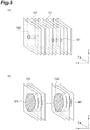
- the computer 14 includes an imaging result reception unit 31, an image processing unit 32, and an analysis unit 33 as functional components, as illustrated in FIG. 4 .
- the imaging result reception unit 31 is a unit that receives imaging data from the imaging unit 13. That is, the imaging result reception unit 31 receives the image data based on the light image including at least the cross section of the fluid in the light image according to the observation light L3 and outputs the image data to the image processing unit 32.
- the image processing unit 32 generates an observation image on the basis of the image data output from the imaging result reception unit 31.
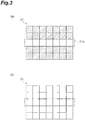
- the samples S flow in a Y-axis direction in the flow cell 2, and the irradiation surface R for the planar light L2 is located in the XZ plane, as described above. Therefore, a plurality of XZ images G1 based on the image data are output to the image processing unit 32 in the Y-axis direction, as illustrated in FIG. 5(a) .
- the image processing unit 32 specifies pixels constituting an XZ image (an observation image such as a fluorescence image) M1 of the sample S for each XZ image G1, and sets pixel values of pixels that do not constitute the XZ image M1 of the sample S in each XZ image G1 to a predetermined value (for example, zero) to generate an XZ image G1 in which a background has been suppressed.
- the image processing unit 32 outputs the plurality of generated XZ images G1 to the analysis unit 33 as XYZ data.
- the image processing unit 32 may extract an XZ image G2 corresponding to a portion including the XZ image M1 of the sample S from each XZ image G1 as illustrated in FIG. 5(b) , and output the plurality of XZ images G2 to the analysis unit 33 as XYZ data.
- the analysis unit 33 sets the XZ images G1 and G2 in the XYZ data received from the image processing unit 32 as analysis targets.
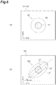
- FIG. 6(a) is a diagram illustrating an example of the XZ image M1 of the sample S that appears in the XZ image G1.
- a spreading component in a three-dimensional direction of the sample S in the XZ image G1 an optical aberration caused by an optical aberration of the lenses or the like included in the image formation unit 17 is included in an X-axis direction and a Z-axis direction. Therefore, as illustrated in FIG. 6(a) , a real image T1 of the light image according to the observation light L3, and a blur T2 of the real image generated around the real image T1 can be included in the XZ image M1 of the sample S that appears in the XZ image G1.
- FIG. 6(b) is a diagram illustrating an example of a YZ image M2 of the sample S that appears in the YZ image G3.
- a virtual image based on a profile of the planar light L2 with which the sample S is irradiated is included in a Y-axis direction. Therefore, as illustrated in FIG.
- a real image U1 of the light image according to the observation light L3, a virtual image U2 based on the profile of the planar light L2, and a blur U3 of the virtual image and the real image can be included in the YZ image M2 of the sample S that appears in the YZ image.
- the analysis unit 33 analyzes a light intensity profile of the sample S in the flow direction of the fluid with the XZ images G1 and G2 or the YZ image G3 being analysis targets.
- the analysis unit 33 generates the light intensity profile of the sample S on the basis of the XZ images G1 and G2 in the XYZ image.
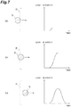
- FIGS. 7A to 7C are diagrams illustrating a state in which a light intensity profile is acquired for a sample.
- the light intensity profile of the sample S is represented as a temporal waveform of the light intensity of the observation light L3. As illustrated in FIG.
- the light intensity increases, and the light intensity has a peak when the sample S passes through a central portion of the irradiation surface R.
- the light intensity decreases, and the light intensity profile having a substantially Gaussian shape as a whole is obtained.
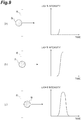
- FIGS. 8(a) to 8(c) are diagrams illustrating a state in which the light intensity profile is acquired for samples having different sizes.
- a case in which a size of the sample S is smaller than that in the case of FIG. 7 , and the flow rate and light quantity of the sample S are the same as those in the case of FIG. 7 is illustrated.
- time required for the sample S to pass through the irradiation surface R is shortened, and an integrated value of the light intensity of the sample S is the same as in the case of FIG. 7 . Therefore, the temporal waveform of the light intensity is a steep waveform of which a full width at half maximum is smaller and a peak is higher than in the case of FIG. 7 .
- the analysis unit 33 may be assumed for simplification of a process that a flow rate of the sample flow F1 is constant at any position in a radial direction of the flow.
- the analysis unit 33 may execute analysis of the flow rate and correction of the light intensity profile based on the analyzed flow rate in consideration of a difference between the flow rate at the central portion and the flow rate at the outer portion of the sample flow F1.
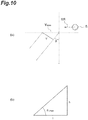
- An angle of the virtual image U2 with respect to a Y-axis direction in the YZ image M2 of the sample S illustrated in FIG. 6(b) (hereinafter referred to as a "virtual image angle ⁇ virtual ”) can be used for analysis of the flow rate.
- a moving speed of the sample S (a flow rate of the sample flow F1) is SR
- a field of view of the image formation unit 17 is V
- an inclination angle of the observation axis with respect to the irradiation surface is ⁇
- a distance in a flow direction at the inclination angle ⁇ of the field of view V is Y Reso as illustrated in FIG. 10(a)
- the moving speed SR of the sample S may be calculated as the amount of movement of the sample S during an exposure period. (Equation 1)
- Y Reso V / cos ⁇ ⁇
- the moving speed SR of the sample S may be obtained using the XZ images G1 and G2.
- the analysis unit 33 can specify positions of the virtual image U2 based on the profile of the planar light L2 in the plurality of XZ images G1 and G2 constituting the XYZ data, or the blur U3 of the virtual image and the real image to obtain the virtual image angle ⁇ virtual , and can calculate the moving speed SR of the sample S on the basis of the virtual image angle ⁇ virtual and Equations (1) and (2).
- FIG. 11 is a flowchart illustrating an example of the sample observation method using the sample observation device 1 illustrated in FIG. 1 .
- this sample observation method includes a fluid formation step (step S01), an irradiation step (step S02), an image formation step (step S03), an imaging step (step S04), and an analysis step (step S05).
- a fluid containing the samples S flows in the flow cell 2.
- a laminar flow is formed of the sample flow F1 and the sheath flow F2 in the pipe 5 of the flow cell 2, for example, through pressure adjustment using a compressor. Accordingly, the sample flow F1 surrounded by the sheath flow F2 is formed in the flow cell 2, and the samples S sequentially flow in the flow cell 2.
- the sample S is irradiated with the planar light L2.
- the light source 15 is driven on the basis of a control signal from the computer 14, and the light L 1 is output from the light source 15.
- the light L1 output from the light source 15 is shaped into the planar light L2 by the planar light formation unit 16, and the sample S flowing in the flow cell 2 is irradiated with the light L1.
- the observation light L3 generated on the sample S due to the irradiation with the planar light L2 is formed as an image by the image formation unit 17.
- the observation light L3 is formed as an image on the image formation surface of the two-dimensional imaging element 20 according to the observation axis P2 inclined with respect to the irradiation surface R.
- a light image including at least a cross section of the fluid among the light images of the observation light L3 formed by the image formation unit 17 is captured.
- the light image is captured through the subarray readout of the two-dimensional imaging element 20, for example.
- the plurality of XZ images G1 in the Y-axis direction output from the two-dimensional imaging element 20 are processed by the image processing unit 32, and a plurality of XZ images G1 with a reduced background are generated.
- the plurality of generated XZ images G1 are output to the analysis unit 33 as XYZ data.
- the light intensity profile of the sample S in the flow direction of the fluid is analyzed.
- the temporal waveform of the light intensity of the observation light L3 is analyzed for each sample S on the basis of the XYZ data.
- the flow rate of the sample S may be calculated using the virtual image angle ⁇ virtual of the sample S, and the light intensity profile may be corrected on the basis of the calculated flow rate.
- the correction of the light intensity profile based on the calculated flow rate is effective, for example, when the flow rate at the central portion and the flow rate at the outer portion of the sample flow F1 as described above are different or when the light intensity profiles obtained through different observations are compared.
- the sample S flowing in the flow cell 2 is irradiated with the planar light L2, and the observation light L3 from the sample S is formed as an image by the image formation unit 17 having the observation axis P2 inclined with respect to the irradiation surface R for the planar light L2. Further, the observation light L3 formed as an image by the image formation unit 17 is imaged by the two-dimensional imaging element 20, and image data based on the light image including at least a cross section of the fluid is generated. Therefore, even when there are a plurality of samples S in the cross section of the fluid, the analysis unit 33 can separate the observation light L3 from the respective samples S and analyze the light intensity profile. Therefore, even when the throughput has been improved, the samples S can be appropriately observed.
- the optical axis P1 of the planar light L2 due to the irradiation unit 11 is orthogonal to the incidence surface 5a of the planar light L2 in the flow cell 2. Further, the optical axis P1 of the planar light L2 from the irradiation unit 11 is orthogonal to a direction in which the fluid flows in the flow cell 2. Accordingly, position correction or the like of the image data acquired by the two-dimensional imaging element 20 becomes unnecessary, and the light intensity profile analysis process can be facilitated.
- the analysis unit 33 analyzes the flow rate of the sample S on the basis of the image data, and corrects the light intensity profile on the basis of the analyzed flow rate.
- the flow rate of the sample flow F1 in the flow cell 2 may be different between a center side of the sample flow F1 and surroundings thereof. In this case, it is conceivable that it would be difficult to discriminate whether the difference in light intensity profile between the samples S is based on a difference in size between the samples S or on a difference between flow rates. Therefore, when the flow rate of the sample S is analyzed, the flow rate unevenness of the sample flow F1 can be allowed, and control of flow cytometry is facilitated. Further, analysis accuracy of the sample S can be increased through correction of the light intensity profile.
- the light image including at least a cross section of the fluid among the light images from the observation light L3 formed by the image formation unit 17 can be captured through subarray readout of the two-dimensional imaging element 20.
- the further improvement of a throughput can be achieved.
- the embodiment since both a position at which the sample S flows in the flow cell 2 and the flow rate can be corrected, control of the flow cytometry can be performed roughly. Therefore, the embodiment can also be applied to a flow cytometry in which the sheath flow F2 is not used. Further, in the embodiment, it is possible to separate the observation light L3 generated from the sample S and the autofluorescent light generated from the sample flow F1 and the sheath flow F2 flowing in the flow cell 2.
- the present invention is not limited to the above embodiment.
- the optical axis P1 of the planar light L2 and the incidence surface 5a of the flow cell 2 may not necessarily be orthogonal to each other, and the optical axis P1 of the planar light L2 and the flow direction of the sample S may not necessarily be orthogonal to each other.
- a plurality of pairs of image formation unit 17 and two-dimensional imaging elements 20 may be disposed.
- the observation range can be expanded, and observation light L3 having a plurality of different wavelengths can be observed.
- a plurality of two-dimensional imaging elements 20 may be disposed for a single image formation unit 17, or a single two-dimensional imaging element 20 may be disposed for a plurality of image formation units 17.
- the light source 15 may include a plurality of light sources that output light having different wavelengths.
- the sample S can be irradiated with the planar light L2 having different wavelengths as excitation light.
- a prism may be disposed in the image formation unit 17 to reduce astigmatism.
- a prism may be disposed on the rear side of the objective lens 18 (between the objective lens 18 and the two-dimensional imaging element 20).
- an imaging surface of the two-dimensional imaging element 20 may be inclined with respect to the observation axis P2.
- a configuration in which a dichroic mirror or a prism is disposed between the image formation unit 17 and the two-dimensional imaging element 20 to perform wavelength separation of the observation light L3 may be adopted.
- FIG. 12 is a diagram illustrating an example in which the field of view is calculated in the sample observation device.
- the image formation unit 17 is located in a medium A having a refractive index n1
- the irradiation surface of the planar light is located in a medium B having a refractive index n2.
- Equations (3) to (5) below are established.
- V ′ L / tan ⁇ ⁇ ′
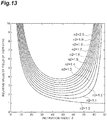
- FIG. 13 is a diagram illustrating a relationship between the inclination angle of the observation axis and the resolution.
- a horizontal axis indicates the inclination angle ⁇ of the observation axis
- a vertical axis is a relative value V'/V of the field of view.
- the value V'/V when the refractive index n1 of the medium A is 1 (air) and the refractive index n2 of the medium B is changed from 1.0 to 2.0 in increments of 0.1 is plotted with respect to the inclination angle ⁇ . It is shown that the smaller the value V'/V, the higher the resolution in a depth direction of the sample (hereinafter referred to as a "Z-direction resolution"), and the greater the value, the lower the Z-direction resolution.
- the inclination angle ⁇ at which the Z-direction resolution is maximized tends to decrease as the difference between the refractive index n1 and the refractive index n2 increases.
- the inclination angle ⁇ at which the Z-direction resolution is maximized is in a range of about 47° to about 57°.
- the refractive index n2 is 1.33 (water)
- the inclination angle ⁇ at which the Z-direction resolution is maximized is estimated to be about 52°.
- the inclination angle ⁇ at which the Z-direction resolution is maximized is estimated to be about 48°.
- parameters for determining the Z-direction resolution are L and ⁇ ', L is determined from ⁇ , and ⁇ ' is determined from ⁇ and (n1/n2). Therefore, the Z-direction resolution is determined from two parameters of ⁇ and (n1/n2) in a state in which V is determined. Since (n1/n2) is determined according to a measurement environment, ⁇ is adjusted to increase the Z-direction resolution. However, in simple adjustment of ⁇ , there is a theoretical limit value in improving the Z-direction resolution, as illustrated in FIG. 13 .
- the image formation unit 17 includes an objective lens 18 and an image formation lens 19, and a first optical element 41 is disposed between the flow cell 2 and the objective lens 18 in the image formation unit 17.
- the first optical element 41 is an optical element having a refractive index greater than that of the disposition space of the image formation unit 17.
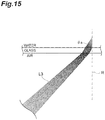
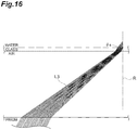
- the first optical element 41 is an optical element that increases an inclination angle ⁇ s (see FIGS. 15 and 16 ) of the observation light L3 emitted from the sample S with respect to the irradiation surface R for the planar light L2, in comparison with a case in which the first optical element 41 is not disposed.
- the disposition space of the image formation unit 17 is filled with, for example, a medium such as air, water, or oil. In the example of FIG. 14 , the image formation unit 17 is disposed in the air.
- the first optical element 41 includes, for example, a wedge prism.
- the wedge prism is a prism in which one main surface and the other main surface are parallel in one direction, but the other main surface is inclined at a certain angle with respect to the one main surface in the other direction orthogonal to the one direction. That is, the wedge prism is a prism of which a thickness changes uniformly in the one direction and does not change in the other direction orthogonal to the one direction. Therefore, the wedge prism functions as a non-axisymmetric optical element that bends rays on one axis of the observation light L3 with a predetermined declination according to an incident position, but does not bend rays on the other axis of the observation light L3 orthogonal to the one axis.
- the first optical element 41 is a doublet prism in which a pair of wedge prisms are combined.
- the doublet prism is configured of abutting inclined surfaces of a pair of wedge prisms and is disposed at a position close to the flow cell 2 so that a flat surface of one wedge prism is parallel to a side surface portion of the pipe 5 of the flow cell 2 on an optical path of the observation light L3 between the flow cell 2 and the objective lens 18.
- an inclination angle ⁇ of the observation axis P2 of the image formation unit 17 is 45°
- the inclination angle ⁇ s of the observation light L3 emitted from the sample S is about 32° as illustrated in FIG.
- the Z-direction resolution is estimated to be about 2.2.
- the inclination angle ⁇ s of the observation light L3 emitted from the sample S is about 35° as illustrated in FIG. 16 .
- the Z-direction resolution of the observation image can be achieved due to the disposition of the first optical element 41 even when the observation axis P2 of the image formation unit 17 is inclined with respect to the irradiation surface R for the planar light L2. Further, when the first optical element 41 is the wedge prism, reduction of the astigmatism of the observation light L3 is achieved, and when the first optical element 41 is the doublet prism that is a combination of a pair of wedge prisms, reduction of chromatic aberration of the observation light L3 is also achieved.
- the flat surface of the first optical element 41 and the side surface portion of the pipe 5 of the flow cell 2 may be in close contact with each other.
- the inclination angle ⁇ s of the observation light L3 emitted from the sample S can be further increased to some degree, and further improvement of the Z-direction resolution can be achieved. Further, aberration correction of the observation light L3 is facilitated.
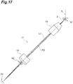
- a second optical element 42 may be disposed between the image formation lens 19 and the two-dimensional imaging element 20, as illustrated in FIG. 17 .
- the second optical element 42 is a non-axisymmetric optical element that bends rays on one axis of the observation light L3 and does not bend rays on the other axis orthogonal to the one axis.
- the second optical element 42 is a doublet prism in which a pair of wedge prisms have been combined.
- the doublet prism is disposed at a position close to the image formation lens 19 so that a flat surface on one side is orthogonal to the observation axis P2 and an inclined surface on the other side is inclined with respect to the observation axis P2 on an optical path of the observation light L3 between the image formation lens 19 and the two-dimensional imaging element 20. With this disposition of the second optical element 42, the reduction of the astigmatism of the observation light L3 can be further achieved.
- the second optical element 42 is the wedge prism
- the reduction of the astigmatism of the observation light L3 can be further achieved
- the second optical element 42 is the doublet prism that is a combination of a pair of wedge prisms such that reduction of the chromatic aberration of the observation light L3 can be further achieved.
Landscapes
- Physics & Mathematics (AREA)
- General Physics & Mathematics (AREA)
- Chemical & Material Sciences (AREA)
- Analytical Chemistry (AREA)
- Optics & Photonics (AREA)
- Life Sciences & Earth Sciences (AREA)
- General Health & Medical Sciences (AREA)
- Health & Medical Sciences (AREA)
- Immunology (AREA)
- Pathology (AREA)
- Biochemistry (AREA)
- Engineering & Computer Science (AREA)
- Multimedia (AREA)
- Dispersion Chemistry (AREA)
- Hydrology & Water Resources (AREA)
- Computer Vision & Pattern Recognition (AREA)
- Investigating Or Analysing Materials By Optical Means (AREA)
- Investigating, Analyzing Materials By Fluorescence Or Luminescence (AREA)
- Microscoopes, Condenser (AREA)
Applications Claiming Priority (2)
| Application Number | Priority Date | Filing Date | Title |
|---|---|---|---|
| JP2017144603 | 2017-07-26 | ||
| PCT/JP2018/020829 WO2019021621A1 (fr) | 2017-07-26 | 2018-05-30 | Dispositif d'observation d'échantillon et procédé d'observation d'échantillon |
Publications (3)
| Publication Number | Publication Date |
|---|---|
| EP3660572A1 true EP3660572A1 (fr) | 2020-06-03 |
| EP3660572A4 EP3660572A4 (fr) | 2021-06-23 |
| EP3660572B1 EP3660572B1 (fr) | 2025-09-03 |
Family
ID=65040465
Family Applications (1)
| Application Number | Title | Priority Date | Filing Date |
|---|---|---|---|
| EP18839164.3A Active EP3660572B1 (fr) | 2017-07-26 | 2018-05-30 | Dispositif d'observation d'échantillon et procédé d'observation d'échantillon |
Country Status (5)
| Country | Link |
|---|---|
| US (1) | US11874224B2 (fr) |
| EP (1) | EP3660572B1 (fr) |
| JP (1) | JP7058271B2 (fr) |
| CN (1) | CN110945403A (fr) |
| WO (1) | WO2019021621A1 (fr) |
Families Citing this family (5)
| Publication number | Priority date | Publication date | Assignee | Title |
|---|---|---|---|---|
| WO2019021621A1 (fr) * | 2017-07-26 | 2019-01-31 | 浜松ホトニクス株式会社 | Dispositif d'observation d'échantillon et procédé d'observation d'échantillon |
| US11032481B2 (en) * | 2018-07-06 | 2021-06-08 | Medos International Sarl | Camera scope electronic variable prism |
| EP4137864B1 (fr) | 2020-06-01 | 2025-02-19 | Hamamatsu Photonics K.K. | Dispositif et procédé d'observation d'échantillon |
| JP2022082060A (ja) * | 2020-11-20 | 2022-06-01 | 日産自動車株式会社 | 二次電池 |
| EP4320426A4 (fr) * | 2021-04-07 | 2025-03-12 | Illumina, Inc. | Motif d'éclairage adaptable pour analyse d'échantillon |
Family Cites Families (55)
| Publication number | Priority date | Publication date | Assignee | Title |
|---|---|---|---|---|
| US3705771A (en) * | 1970-01-14 | 1972-12-12 | Bio Physics Systems Inc | Photoanalysis apparatus |
| US3910702A (en) * | 1974-02-12 | 1975-10-07 | Particle Technology Inc | Apparatus for detecting particles employing apertured light emitting device |
| US3960449A (en) * | 1975-06-05 | 1976-06-01 | The Board Of Trustees Of Leland Stanford Junior University | Measurement of angular dependence of scattered light in a flowing stream |
| US4498766A (en) * | 1982-03-25 | 1985-02-12 | Becton, Dickinson And Company | Light beam focal spot elongation in flow cytometry devices |
| US5121988A (en) * | 1989-10-04 | 1992-06-16 | Tsi Incorporated | Single particle detector method and apparatus utilizing light extinction within a sheet of light |
| US5671046A (en) * | 1996-07-01 | 1997-09-23 | Particle Measuring Systems, Inc. | Device and method for optically detecting particles in a free liquid stream |
| ATE514072T1 (de) * | 1997-05-05 | 2011-07-15 | Chemometec As | Verfahren zur bestimmung von teilchen in einer flüssigen probe |
| JP3304053B2 (ja) | 1997-05-30 | 2002-07-22 | 松下電器産業株式会社 | 光ヘッドおよび光ディスク装置 |
| US6067157A (en) * | 1998-10-09 | 2000-05-23 | University Of Washington | Dual large angle light scattering detection |
| JP3658256B2 (ja) | 1998-11-20 | 2005-06-08 | 株式会社堀場製作所 | 粒径分布測定装置並びにこの装置に用いるアレイ検出器 |
| US6608682B2 (en) | 1999-01-25 | 2003-08-19 | Amnis Corporation | Imaging and analyzing parameters of small moving objects such as cells |
| US7217573B1 (en) * | 1999-10-05 | 2007-05-15 | Hitachi, Ltd. | Method of inspecting a DNA chip |
| US6784981B1 (en) * | 2000-06-02 | 2004-08-31 | Idexx Laboratories, Inc. | Flow cytometry-based hematology system |
| WO2002031467A1 (fr) * | 2000-10-12 | 2002-04-18 | Amnis Corporation | Cavite a passages multiples destinee a l'eclairage et a l'excitation d'objets en mouvement |
| JP4042323B2 (ja) | 2000-11-30 | 2008-02-06 | 日本ビクター株式会社 | 撮像装置 |
| WO2003021231A2 (fr) * | 2001-09-05 | 2003-03-13 | Genicon Sciences Corporation | Procede et appareil pour la normalisation et la deconvolution de donnees de dosage |
| JP4242617B2 (ja) * | 2002-08-28 | 2009-03-25 | オリンパス株式会社 | 走査型レーザ顕微鏡システム |
| US8634072B2 (en) * | 2004-03-06 | 2014-01-21 | Michael Trainer | Methods and apparatus for determining characteristics of particles |
| US7075647B2 (en) * | 2004-06-30 | 2006-07-11 | Beckman Coulter, Inc. | Back-scatter detection in flow cytometers |
| US7113266B1 (en) * | 2005-03-30 | 2006-09-26 | Beckman Coulter, Inc. | Flow cytometer for differentiating small particles in suspension |
| US7456960B2 (en) * | 2005-06-06 | 2008-11-25 | Particle Measuring Systems, Inc. | Particle counter with improved image sensor array |
| WO2007067999A2 (fr) * | 2005-12-09 | 2007-06-14 | Amnis Corporation | Systeme d'imagerie a profondeur de champ etendue pour analyse d'objets a grande vitesse |
| DE102007045897A1 (de) * | 2007-09-26 | 2009-04-09 | Carl Zeiss Microimaging Gmbh | Verfahren zur mikroskopischen dreidimensionalen Abbildung einer Probe |
| JP2009110765A (ja) * | 2007-10-29 | 2009-05-21 | Omron Corp | 面光源装置及び液晶表示装置 |
| CN101910821B (zh) | 2007-12-04 | 2012-09-05 | 粒子监测系统有限公司 | 非正交粒子检测系统和方法 |
| JP5216318B2 (ja) * | 2007-12-27 | 2013-06-19 | 株式会社日立ハイテクノロジーズ | 蛍光検出装置 |
| DK200801722A (en) | 2008-12-05 | 2010-06-06 | Unisensor As | Optical sectioning of a sample and detection of particles in a sample |
| JP5667079B2 (ja) * | 2008-12-18 | 2015-02-12 | アズビル株式会社 | 粒径及び蛍光の同時検出のための小型検出器 |
| JP5382852B2 (ja) * | 2009-02-06 | 2014-01-08 | 株式会社オンチップ・バイオテクノロジーズ | 使い捨てチップ型フローセルとそれを用いたフローサイトメーター |
| JP5537347B2 (ja) | 2009-11-30 | 2014-07-02 | シスメックス株式会社 | 粒子分析装置 |
| US8477307B1 (en) * | 2012-01-26 | 2013-07-02 | Ann Rachel Yufa | Methods and apparatus for biomedical agent multi-dimension measuring and analysis |
| EP2823297B1 (fr) * | 2012-03-05 | 2023-04-19 | Boehringer Ingelheim International GmbH | Procédé pour l'évaluation de la stabilité colloïdale d'une composition pharmaceutique liquide |
| US20170045441A1 (en) * | 2012-05-09 | 2017-02-16 | Archimej Technology | Sample analysis methods |
| DK2948761T3 (da) * | 2013-01-23 | 2023-09-04 | California Inst Of Techn | Indstilleligt miniaturelaserspektrometer til registrering af en sporgas |
| EP2988113B1 (fr) * | 2013-04-18 | 2024-09-18 | Nipro Corporation | Dispositif de mesure de concentration de fluide |
| US9372143B2 (en) | 2013-05-15 | 2016-06-21 | Captl Llc | Scanning image flow cytometer |
| CN103308440A (zh) * | 2013-05-28 | 2013-09-18 | 香港浸会大学深圳研究院 | 一种流式荧光显微成像装置及方法 |
| DE102013112595B4 (de) | 2013-11-15 | 2024-08-01 | Carl Zeiss Microscopy Gmbh | Anordnung zur Lichtblattmikroskopie |
| DE102013112596B4 (de) | 2013-11-15 | 2023-12-28 | Carl Zeiss Microscopy Gmbh | Anordnung zur Lichtblattmikroskopie |
| US10061111B2 (en) * | 2014-01-17 | 2018-08-28 | The Trustees Of Columbia University In The City Of New York | Systems and methods for three dimensional imaging |
| US9308306B2 (en) * | 2014-02-24 | 2016-04-12 | Fresenius Medical Care Holdings, Inc. | Self calibrating blood chamber |
| US9891155B2 (en) * | 2014-05-23 | 2018-02-13 | 7108789 Manitoba Inc. | Coulter mounted soil constituent sensor |
| US10900885B2 (en) * | 2014-12-19 | 2021-01-26 | Captl Llc | Flow cytometry using hydrodynamically planar flow |
| JP6635052B2 (ja) * | 2015-02-05 | 2020-01-22 | 株式会社ニコン | 構造化照明顕微鏡、及び観察方法 |
| CN104897591B (zh) | 2015-06-08 | 2018-09-21 | 苏州谱道光电科技有限公司 | 样品测量装置 |
| JP6796917B2 (ja) | 2015-09-18 | 2020-12-09 | シスメックス株式会社 | 粒子撮像装置および粒子撮像方法 |
| JP6667927B2 (ja) * | 2016-03-04 | 2020-03-18 | 国立研究開発法人理化学研究所 | 光検出装置、及び、生体情報取得装置 |
| US11385451B2 (en) * | 2017-02-08 | 2022-07-12 | The Regents Of The University Of California | Selective plane illumination in the conventional inverted microscope geometry by side illumination |
| WO2019021621A1 (fr) * | 2017-07-26 | 2019-01-31 | 浜松ホトニクス株式会社 | Dispositif d'observation d'échantillon et procédé d'observation d'échantillon |
| JP6932036B2 (ja) * | 2017-07-31 | 2021-09-08 | シスメックス株式会社 | 細胞撮像方法、細胞撮像装置、粒子撮像方法および粒子撮像装置 |
| EP3757550A4 (fr) * | 2017-12-27 | 2021-12-15 | Riken | Dispositif d'analyse spectroscopique, procédé d'analyse spectroscopique, programme, support d'enregistrement et microscope |
| JP7207860B2 (ja) * | 2018-04-09 | 2023-01-18 | 浜松ホトニクス株式会社 | 試料観察装置 |
| JP7260308B2 (ja) * | 2019-01-24 | 2023-04-18 | リオン株式会社 | 流体中浮遊物質測定用フローセル及び粒子計数装置 |
| JP7270907B2 (ja) * | 2019-02-27 | 2023-05-11 | 国立大学法人浜松医科大学 | 細胞観察システムおよび細胞観察方法 |
| US11237095B2 (en) * | 2019-04-25 | 2022-02-01 | Particle Measuring Systems, Inc. | Particle detection systems and methods for on-axis particle detection and/or differential detection |
-
2018
- 2018-05-30 WO PCT/JP2018/020829 patent/WO2019021621A1/fr not_active Ceased
- 2018-05-30 JP JP2019532410A patent/JP7058271B2/ja active Active
- 2018-05-30 CN CN201880048132.8A patent/CN110945403A/zh active Pending
- 2018-05-30 US US16/631,927 patent/US11874224B2/en active Active
- 2018-05-30 EP EP18839164.3A patent/EP3660572B1/fr active Active
Also Published As
| Publication number | Publication date |
|---|---|
| US20200158633A1 (en) | 2020-05-21 |
| WO2019021621A1 (fr) | 2019-01-31 |
| EP3660572A4 (fr) | 2021-06-23 |
| JP7058271B2 (ja) | 2022-04-21 |
| EP3660572B1 (fr) | 2025-09-03 |
| US11874224B2 (en) | 2024-01-16 |
| CN110945403A (zh) | 2020-03-31 |
| JPWO2019021621A1 (ja) | 2020-07-09 |
Similar Documents
| Publication | Publication Date | Title |
|---|---|---|
| US11874224B2 (en) | Sample observation device and sample observation method | |
| US10732095B2 (en) | Particle imaging device and particle imaging method | |
| US9715095B2 (en) | Microscope and method for SPIM microscopy | |
| US11449964B2 (en) | Image reconstruction method, device and microscopic imaging device | |
| EP3333612A2 (fr) | Appareil de capture d'images et procédé de capture d'images | |
| CN114402188A (zh) | 颗粒测量装置 | |
| JP6423841B2 (ja) | 試料観察装置及び試料観察方法 | |
| US12189108B2 (en) | Sample observation device and sample observation method | |
| US20150115176A1 (en) | Laser scanning microscope system and method of setting laser-light intensity value | |
| JP2018017970A (ja) | 光シート顕微鏡、及び、光シート顕微鏡の制御方法 | |
| US10379335B2 (en) | Illumination setting method, light sheet microscope apparatus, and recording medium | |
| CN110869747B (zh) | 试样观察装置和试样观察方法 | |
| EP3779555B1 (fr) | Dispositif d'observation d'échantillon | |
| WO2024166705A1 (fr) | Dispositif de mesure de distribution de diamètres de particules, procédé de mesure de distribution de diamètres de particules et programme de mesure de distribution de diamètres de particules | |
| JP2020503565A (ja) | 光学機器の合焦状態を測定するためのシステムと方法 | |
| JP2009192850A (ja) | 自動焦点制御システム | |
| JP7329113B2 (ja) | 試料観察装置 | |
| US12248132B2 (en) | Image capturing apparatus and image capturing method | |
| JP6978562B2 (ja) | 試料観察装置及び試料観察方法 | |
| KR20240118640A (ko) | 촬영 장치 및 촬영 방법 | |
| JP2019023751A (ja) | 試料観察装置及び試料観察方法 |
Legal Events
| Date | Code | Title | Description |
|---|---|---|---|
| STAA | Information on the status of an ep patent application or granted ep patent |
Free format text: STATUS: THE INTERNATIONAL PUBLICATION HAS BEEN MADE |
|
| PUAI | Public reference made under article 153(3) epc to a published international application that has entered the european phase |
Free format text: ORIGINAL CODE: 0009012 |
|
| STAA | Information on the status of an ep patent application or granted ep patent |
Free format text: STATUS: REQUEST FOR EXAMINATION WAS MADE |
|
| 17P | Request for examination filed |
Effective date: 20200116 |
|
| AK | Designated contracting states |
Kind code of ref document: A1 Designated state(s): AL AT BE BG CH CY CZ DE DK EE ES FI FR GB GR HR HU IE IS IT LI LT LU LV MC MK MT NL NO PL PT RO RS SE SI SK SM TR |
|
| AX | Request for extension of the european patent |
Extension state: BA ME |
|
| DAV | Request for validation of the european patent (deleted) | ||
| DAX | Request for extension of the european patent (deleted) | ||
| RIC1 | Information provided on ipc code assigned before grant |
Ipc: G02B 21/00 20060101ALI20210222BHEP Ipc: G02B 21/16 20060101ALI20210222BHEP Ipc: G01N 15/14 20060101ALI20210222BHEP Ipc: G01N 21/64 20060101ALI20210222BHEP Ipc: G01N 21/63 20060101ALI20210222BHEP Ipc: G02B 21/06 20060101AFI20210222BHEP Ipc: G02B 5/04 20060101ALI20210222BHEP Ipc: G02B 21/36 20060101ALI20210222BHEP Ipc: G01N 21/17 20060101ALI20210222BHEP |
|
| A4 | Supplementary search report drawn up and despatched |
Effective date: 20210527 |
|
| RIC1 | Information provided on ipc code assigned before grant |
Ipc: G02B 21/06 20060101AFI20210520BHEP Ipc: G01N 15/14 20060101ALI20210520BHEP Ipc: G01N 21/17 20060101ALI20210520BHEP Ipc: G01N 21/64 20060101ALI20210520BHEP Ipc: G01N 21/63 20060101ALI20210520BHEP Ipc: G02B 21/00 20060101ALI20210520BHEP Ipc: G02B 21/16 20060101ALI20210520BHEP Ipc: G02B 21/36 20060101ALI20210520BHEP Ipc: G02B 5/04 20060101ALI20210520BHEP |
|
| STAA | Information on the status of an ep patent application or granted ep patent |
Free format text: STATUS: EXAMINATION IS IN PROGRESS |
|
| 17Q | First examination report despatched |
Effective date: 20230704 |
|
| GRAP | Despatch of communication of intention to grant a patent |
Free format text: ORIGINAL CODE: EPIDOSNIGR1 |
|
| STAA | Information on the status of an ep patent application or granted ep patent |
Free format text: STATUS: GRANT OF PATENT IS INTENDED |
|
| RIC1 | Information provided on ipc code assigned before grant |
Ipc: G01N 15/10 20060101ALI20250409BHEP Ipc: G01N 15/1434 20240101ALI20250409BHEP Ipc: G02B 5/04 20060101ALI20250409BHEP Ipc: G02B 21/36 20060101ALI20250409BHEP Ipc: G02B 21/16 20060101ALI20250409BHEP Ipc: G02B 21/00 20060101ALI20250409BHEP Ipc: G01N 21/63 20060101ALI20250409BHEP Ipc: G01N 21/64 20060101ALI20250409BHEP Ipc: G01N 21/17 20060101ALI20250409BHEP Ipc: G01N 15/14 20060101ALI20250409BHEP Ipc: G02B 21/06 20060101AFI20250409BHEP |
|
| INTG | Intention to grant announced |
Effective date: 20250430 |
|
| GRAS | Grant fee paid |
Free format text: ORIGINAL CODE: EPIDOSNIGR3 |
|
| GRAA | (expected) grant |
Free format text: ORIGINAL CODE: 0009210 |
|
| STAA | Information on the status of an ep patent application or granted ep patent |
Free format text: STATUS: THE PATENT HAS BEEN GRANTED |
|
| AK | Designated contracting states |
Kind code of ref document: B1 Designated state(s): AL AT BE BG CH CY CZ DE DK EE ES FI FR GB GR HR HU IE IS IT LI LT LU LV MC MK MT NL NO PL PT RO RS SE SI SK SM TR |
|
| REG | Reference to a national code |
Ref country code: GB Ref legal event code: FG4D |
|
| REG | Reference to a national code |
Ref country code: CH Ref legal event code: EP |
|
| REG | Reference to a national code |
Ref country code: DE Ref legal event code: R096 Ref document number: 602018085295 Country of ref document: DE |
|
| REG | Reference to a national code |
Ref country code: IE Ref legal event code: FG4D |
|
| P01 | Opt-out of the competence of the unified patent court (upc) registered |
Free format text: CASE NUMBER: UPC_APP_7981_3660572/2025 Effective date: 20250925 |
|
| REG | Reference to a national code |
Ref country code: NL Ref legal event code: MP Effective date: 20250903 |
|
| PG25 | Lapsed in a contracting state [announced via postgrant information from national office to epo] |
Ref country code: NO Free format text: LAPSE BECAUSE OF FAILURE TO SUBMIT A TRANSLATION OF THE DESCRIPTION OR TO PAY THE FEE WITHIN THE PRESCRIBED TIME-LIMIT Effective date: 20251203 |
|
| REG | Reference to a national code |
Ref country code: LT Ref legal event code: MG9D |
|
| PG25 | Lapsed in a contracting state [announced via postgrant information from national office to epo] |
Ref country code: FI Free format text: LAPSE BECAUSE OF FAILURE TO SUBMIT A TRANSLATION OF THE DESCRIPTION OR TO PAY THE FEE WITHIN THE PRESCRIBED TIME-LIMIT Effective date: 20250903 |
|
| PG25 | Lapsed in a contracting state [announced via postgrant information from national office to epo] |
Ref country code: HR Free format text: LAPSE BECAUSE OF FAILURE TO SUBMIT A TRANSLATION OF THE DESCRIPTION OR TO PAY THE FEE WITHIN THE PRESCRIBED TIME-LIMIT Effective date: 20250903 |
|
| PG25 | Lapsed in a contracting state [announced via postgrant information from national office to epo] |
Ref country code: GR Free format text: LAPSE BECAUSE OF FAILURE TO SUBMIT A TRANSLATION OF THE DESCRIPTION OR TO PAY THE FEE WITHIN THE PRESCRIBED TIME-LIMIT Effective date: 20251204 |
|
| PG25 | Lapsed in a contracting state [announced via postgrant information from national office to epo] |
Ref country code: SE Free format text: LAPSE BECAUSE OF FAILURE TO SUBMIT A TRANSLATION OF THE DESCRIPTION OR TO PAY THE FEE WITHIN THE PRESCRIBED TIME-LIMIT Effective date: 20250903 |
|
| PG25 | Lapsed in a contracting state [announced via postgrant information from national office to epo] |
Ref country code: LV Free format text: LAPSE BECAUSE OF FAILURE TO SUBMIT A TRANSLATION OF THE DESCRIPTION OR TO PAY THE FEE WITHIN THE PRESCRIBED TIME-LIMIT Effective date: 20250903 |
|
| PG25 | Lapsed in a contracting state [announced via postgrant information from national office to epo] |
Ref country code: PL Free format text: LAPSE BECAUSE OF FAILURE TO SUBMIT A TRANSLATION OF THE DESCRIPTION OR TO PAY THE FEE WITHIN THE PRESCRIBED TIME-LIMIT Effective date: 20250903 Ref country code: BG Free format text: LAPSE BECAUSE OF FAILURE TO SUBMIT A TRANSLATION OF THE DESCRIPTION OR TO PAY THE FEE WITHIN THE PRESCRIBED TIME-LIMIT Effective date: 20250903 |
|
| PG25 | Lapsed in a contracting state [announced via postgrant information from national office to epo] |
Ref country code: RS Free format text: LAPSE BECAUSE OF FAILURE TO SUBMIT A TRANSLATION OF THE DESCRIPTION OR TO PAY THE FEE WITHIN THE PRESCRIBED TIME-LIMIT Effective date: 20251203 |
|
| PG25 | Lapsed in a contracting state [announced via postgrant information from national office to epo] |
Ref country code: ES Free format text: LAPSE BECAUSE OF FAILURE TO SUBMIT A TRANSLATION OF THE DESCRIPTION OR TO PAY THE FEE WITHIN THE PRESCRIBED TIME-LIMIT Effective date: 20250903 |
|
| REG | Reference to a national code |
Ref country code: AT Ref legal event code: MK05 Ref document number: 1833729 Country of ref document: AT Kind code of ref document: T Effective date: 20250903 |
|
| PG25 | Lapsed in a contracting state [announced via postgrant information from national office to epo] |
Ref country code: NL Free format text: LAPSE BECAUSE OF FAILURE TO SUBMIT A TRANSLATION OF THE DESCRIPTION OR TO PAY THE FEE WITHIN THE PRESCRIBED TIME-LIMIT Effective date: 20250903 |
|
| PG25 | Lapsed in a contracting state [announced via postgrant information from national office to epo] |
Ref country code: SM Free format text: LAPSE BECAUSE OF FAILURE TO SUBMIT A TRANSLATION OF THE DESCRIPTION OR TO PAY THE FEE WITHIN THE PRESCRIBED TIME-LIMIT Effective date: 20250903 |
|
| PGFP | Annual fee paid to national office [announced via postgrant information from national office to epo] |
Ref country code: GB Payment date: 20260323 Year of fee payment: 9 |
|
| PG25 | Lapsed in a contracting state [announced via postgrant information from national office to epo] |
Ref country code: AT Free format text: LAPSE BECAUSE OF FAILURE TO SUBMIT A TRANSLATION OF THE DESCRIPTION OR TO PAY THE FEE WITHIN THE PRESCRIBED TIME-LIMIT Effective date: 20250903 |
|
| PG25 | Lapsed in a contracting state [announced via postgrant information from national office to epo] |
Ref country code: IT Free format text: LAPSE BECAUSE OF FAILURE TO SUBMIT A TRANSLATION OF THE DESCRIPTION OR TO PAY THE FEE WITHIN THE PRESCRIBED TIME-LIMIT Effective date: 20250903 |
|
| PG25 | Lapsed in a contracting state [announced via postgrant information from national office to epo] |
Ref country code: IS Free format text: LAPSE BECAUSE OF FAILURE TO SUBMIT A TRANSLATION OF THE DESCRIPTION OR TO PAY THE FEE WITHIN THE PRESCRIBED TIME-LIMIT Effective date: 20260103 |
|
| PG25 | Lapsed in a contracting state [announced via postgrant information from national office to epo] |
Ref country code: PT Free format text: LAPSE BECAUSE OF FAILURE TO SUBMIT A TRANSLATION OF THE DESCRIPTION OR TO PAY THE FEE WITHIN THE PRESCRIBED TIME-LIMIT Effective date: 20260105 Ref country code: CZ Free format text: LAPSE BECAUSE OF FAILURE TO SUBMIT A TRANSLATION OF THE DESCRIPTION OR TO PAY THE FEE WITHIN THE PRESCRIBED TIME-LIMIT Effective date: 20250903 |
|
| PG25 | Lapsed in a contracting state [announced via postgrant information from national office to epo] |
Ref country code: EE Free format text: LAPSE BECAUSE OF FAILURE TO SUBMIT A TRANSLATION OF THE DESCRIPTION OR TO PAY THE FEE WITHIN THE PRESCRIBED TIME-LIMIT Effective date: 20250903 Ref country code: SK Free format text: LAPSE BECAUSE OF FAILURE TO SUBMIT A TRANSLATION OF THE DESCRIPTION OR TO PAY THE FEE WITHIN THE PRESCRIBED TIME-LIMIT Effective date: 20250903 |