EP3660657A1 - Procédé de traitement d'image, dispositif de pilotage, panneau d'affichage et dispositif vestimentaire - Google Patents
Procédé de traitement d'image, dispositif de pilotage, panneau d'affichage et dispositif vestimentaire Download PDFInfo
- Publication number
- EP3660657A1 EP3660657A1 EP18833378.5A EP18833378A EP3660657A1 EP 3660657 A1 EP3660657 A1 EP 3660657A1 EP 18833378 A EP18833378 A EP 18833378A EP 3660657 A1 EP3660657 A1 EP 3660657A1
- Authority
- EP
- European Patent Office
- Prior art keywords
- grayscale
- pixel
- region
- transition
- adjacent
- Prior art date
- Legal status (The legal status is an assumption and is not a legal conclusion. Google has not performed a legal analysis and makes no representation as to the accuracy of the status listed.)
- Granted
Links
Images




Classifications
-
- G—PHYSICS
- G09—EDUCATION; CRYPTOGRAPHY; DISPLAY; ADVERTISING; SEALS
- G09G—ARRANGEMENTS OR CIRCUITS FOR CONTROL OF INDICATING DEVICES USING STATIC MEANS TO PRESENT VARIABLE INFORMATION
- G09G3/00—Control arrangements or circuits, of interest only in connection with visual indicators other than cathode-ray tubes
- G09G3/20—Control arrangements or circuits, of interest only in connection with visual indicators other than cathode-ray tubes for presentation of an assembly of a number of characters, e.g. a page, by composing the assembly by combination of individual elements arranged in a matrix no fixed position being assigned to or needed to be assigned to the individual characters or partial characters
- G09G3/2007—Display of intermediate tones
-
- G—PHYSICS
- G09—EDUCATION; CRYPTOGRAPHY; DISPLAY; ADVERTISING; SEALS
- G09G—ARRANGEMENTS OR CIRCUITS FOR CONTROL OF INDICATING DEVICES USING STATIC MEANS TO PRESENT VARIABLE INFORMATION
- G09G5/00—Control arrangements or circuits for visual indicators common to cathode-ray tube indicators and other visual indicators
- G09G5/02—Control arrangements or circuits for visual indicators common to cathode-ray tube indicators and other visual indicators characterised by the way in which colour is displayed
- G09G5/026—Control of mixing and/or overlay of colours in general
-
- G—PHYSICS
- G06—COMPUTING OR CALCULATING; COUNTING
- G06F—ELECTRIC DIGITAL DATA PROCESSING
- G06F1/00—Details not covered by groups G06F3/00 - G06F13/00 and G06F21/00
- G06F1/16—Constructional details or arrangements
- G06F1/1613—Constructional details or arrangements for portable computers
- G06F1/163—Wearable computers, e.g. on a belt
-
- G—PHYSICS
- G06—COMPUTING OR CALCULATING; COUNTING
- G06F—ELECTRIC DIGITAL DATA PROCESSING
- G06F1/00—Details not covered by groups G06F3/00 - G06F13/00 and G06F21/00
- G06F1/16—Constructional details or arrangements
- G06F1/1613—Constructional details or arrangements for portable computers
- G06F1/1633—Constructional details or arrangements of portable computers not specific to the type of enclosures covered by groups G06F1/1615 - G06F1/1626
- G06F1/1637—Details related to the display arrangement, including those related to the mounting of the display in the housing
-
- G—PHYSICS
- G06—COMPUTING OR CALCULATING; COUNTING
- G06F—ELECTRIC DIGITAL DATA PROCESSING
- G06F3/00—Input arrangements for transferring data to be processed into a form capable of being handled by the computer; Output arrangements for transferring data from processing unit to output unit, e.g. interface arrangements
- G06F3/14—Digital output to display device ; Cooperation and interconnection of the display device with other functional units
- G06F3/147—Digital output to display device ; Cooperation and interconnection of the display device with other functional units using display panels
-
- G—PHYSICS
- G06—COMPUTING OR CALCULATING; COUNTING
- G06T—IMAGE DATA PROCESSING OR GENERATION, IN GENERAL
- G06T5/00—Image enhancement or restoration
- G06T5/20—Image enhancement or restoration using local operators
-
- G—PHYSICS
- G06—COMPUTING OR CALCULATING; COUNTING
- G06T—IMAGE DATA PROCESSING OR GENERATION, IN GENERAL
- G06T5/00—Image enhancement or restoration
- G06T5/70—Denoising; Smoothing
-
- G—PHYSICS
- G09—EDUCATION; CRYPTOGRAPHY; DISPLAY; ADVERTISING; SEALS
- G09G—ARRANGEMENTS OR CIRCUITS FOR CONTROL OF INDICATING DEVICES USING STATIC MEANS TO PRESENT VARIABLE INFORMATION
- G09G3/00—Control arrangements or circuits, of interest only in connection with visual indicators other than cathode-ray tubes
- G09G3/20—Control arrangements or circuits, of interest only in connection with visual indicators other than cathode-ray tubes for presentation of an assembly of a number of characters, e.g. a page, by composing the assembly by combination of individual elements arranged in a matrix no fixed position being assigned to or needed to be assigned to the individual characters or partial characters
- G09G3/2003—Display of colours
-
- G—PHYSICS
- G09—EDUCATION; CRYPTOGRAPHY; DISPLAY; ADVERTISING; SEALS
- G09G—ARRANGEMENTS OR CIRCUITS FOR CONTROL OF INDICATING DEVICES USING STATIC MEANS TO PRESENT VARIABLE INFORMATION
- G09G3/00—Control arrangements or circuits, of interest only in connection with visual indicators other than cathode-ray tubes
- G09G3/20—Control arrangements or circuits, of interest only in connection with visual indicators other than cathode-ray tubes for presentation of an assembly of a number of characters, e.g. a page, by composing the assembly by combination of individual elements arranged in a matrix no fixed position being assigned to or needed to be assigned to the individual characters or partial characters
- G09G3/22—Control arrangements or circuits, of interest only in connection with visual indicators other than cathode-ray tubes for presentation of an assembly of a number of characters, e.g. a page, by composing the assembly by combination of individual elements arranged in a matrix no fixed position being assigned to or needed to be assigned to the individual characters or partial characters using controlled light sources
- G09G3/30—Control arrangements or circuits, of interest only in connection with visual indicators other than cathode-ray tubes for presentation of an assembly of a number of characters, e.g. a page, by composing the assembly by combination of individual elements arranged in a matrix no fixed position being assigned to or needed to be assigned to the individual characters or partial characters using controlled light sources using electroluminescent panels
- G09G3/32—Control arrangements or circuits, of interest only in connection with visual indicators other than cathode-ray tubes for presentation of an assembly of a number of characters, e.g. a page, by composing the assembly by combination of individual elements arranged in a matrix no fixed position being assigned to or needed to be assigned to the individual characters or partial characters using controlled light sources using electroluminescent panels semiconductive, e.g. using light-emitting diodes [LED]
- G09G3/3208—Control arrangements or circuits, of interest only in connection with visual indicators other than cathode-ray tubes for presentation of an assembly of a number of characters, e.g. a page, by composing the assembly by combination of individual elements arranged in a matrix no fixed position being assigned to or needed to be assigned to the individual characters or partial characters using controlled light sources using electroluminescent panels semiconductive, e.g. using light-emitting diodes [LED] organic, e.g. using organic light-emitting diodes [OLED]
-
- G—PHYSICS
- G06—COMPUTING OR CALCULATING; COUNTING
- G06T—IMAGE DATA PROCESSING OR GENERATION, IN GENERAL
- G06T2207/00—Indexing scheme for image analysis or image enhancement
- G06T2207/20—Special algorithmic details
- G06T2207/20021—Dividing image into blocks, subimages or windows
-
- G—PHYSICS
- G06—COMPUTING OR CALCULATING; COUNTING
- G06T—IMAGE DATA PROCESSING OR GENERATION, IN GENERAL
- G06T2207/00—Indexing scheme for image analysis or image enhancement
- G06T2207/20—Special algorithmic details
- G06T2207/20172—Image enhancement details
- G06T2207/20192—Edge enhancement; Edge preservation
-
- G—PHYSICS
- G09—EDUCATION; CRYPTOGRAPHY; DISPLAY; ADVERTISING; SEALS
- G09G—ARRANGEMENTS OR CIRCUITS FOR CONTROL OF INDICATING DEVICES USING STATIC MEANS TO PRESENT VARIABLE INFORMATION
- G09G2310/00—Command of the display device
- G09G2310/02—Addressing, scanning or driving the display screen or processing steps related thereto
- G09G2310/0232—Special driving of display border areas
-
- G—PHYSICS
- G09—EDUCATION; CRYPTOGRAPHY; DISPLAY; ADVERTISING; SEALS
- G09G—ARRANGEMENTS OR CIRCUITS FOR CONTROL OF INDICATING DEVICES USING STATIC MEANS TO PRESENT VARIABLE INFORMATION
- G09G2320/00—Control of display operating conditions
- G09G2320/02—Improving the quality of display appearance
- G09G2320/0271—Adjustment of the gradation levels within the range of the gradation scale, e.g. by redistribution or clipping
-
- G—PHYSICS
- G09—EDUCATION; CRYPTOGRAPHY; DISPLAY; ADVERTISING; SEALS
- G09G—ARRANGEMENTS OR CIRCUITS FOR CONTROL OF INDICATING DEVICES USING STATIC MEANS TO PRESENT VARIABLE INFORMATION
- G09G2340/00—Aspects of display data processing
- G09G2340/14—Solving problems related to the presentation of information to be displayed
Definitions
- the embodiments of the present disclosure relate to an image processing method, a drive device, a display panel, and a wearable device.
- mainstream display devices include liquid crystal display (LCD) panels or active-matrix organic light-emitting diode (AMOLED) display panels.
- LCD liquid crystal display
- AMOLED active-matrix organic light-emitting diode
- the LCD panel has the advantages of rapider speed, higher contrast, wider viewing angle, lower power consumption, smaller module thickness, etc.
- the wearable product When the AMOLED is applied to a wearable product, the wearable product can be thinner and lightweight and portable in shape and specification. Therefore, currently, more and more wearable products adopt AMOLED as the display panel.
- most wearable products e.g., smart watches, require a round display.
- pixels arranged in an array are taken as a pixel array of a non-rectangular display such as a round display, due to problems such as real pixel arrangement, in an edge portion of the round display, for example, a severe sawtooth sense may occur at an intersection of the contours of the round display, resulting in poor viewing experience for customers.
- At least one embodiment of the present disclosure provides an image processing method of a display panel, the display panel comprises a display image region and a peripheral region; the peripheral region comprises grayscale transition regions; the grayscale transition regions are adjacent to the display image region; the display image region comprises a plurality of display pixels arranged along a row direction and a column direction; and the image processing method comprises: determining an adjacent display pixel adjacent to each grayscale transition region in the row direction or in the column direction in the display image region according to a position of the grayscale transition region; determining a transition pixel in the grayscale transition region; acquiring a first pixel grayscale, in which the first pixel grayscale is a grayscale of the adjacent display pixel; acquiring a second pixel grayscale; adjusting a third pixel grayscale of the transition pixel according to the first pixel grayscale, the second pixel grayscale and the transition pixel, in which the third pixel grayscale is between the first pixel grayscale and the second pixel grayscale; and transmitting the third pixel grayscale to the display panel
- the peripheral region further includes a background image region; the background image region includes a plurality of background pixels arranged along the row direction and the column direction; and acquiring the second pixel grayscale includes: determining an adjacent background pixel adjacent to the grayscale transition region in the row direction or in the column direction in the background image region, in which the second pixel grayscale is a grayscale of the adjacent background pixel.
- an edge of the display image region includes a polygonal line segment formed by connection of line segments extending along the row direction and the column direction, the row direction and the column direction are perpendicular to each other; and determining the transition pixel in the grayscale transition region includes: forming a virtual rectangular area in the peripheral region by taking adjacent two line segments as adjacent two sides; and determining a quantity and an arrangement mode of transition pixels in the grayscale transition region according to the virtual rectangular area.
- determining a quantity and an arrangement mode of transition pixels in the grayscale transition region according to the virtual rectangular area includes: when the virtual rectangular area includes one row and a plurality of columns of pixels, determining that the grayscale transition region includes a plurality of transition pixels disposed in the one row and adjacent to the display image region in the virtual rectangular area; when the virtual rectangular area includes a plurality of rows and one column of pixels, determining that the grayscale transition region includes a plurality of transition pixels disposed in the one column and adjacent to the display image region in the virtual rectangular area; and when the virtual rectangular area includes one row and one column of pixels, determining that the grayscale transition region includes one transition pixel adjacent to the display image region in the virtual rectangular area.
- a shape of the display image region includes a non-rectangular shape.
- the non-rectangular shape includes a round.
- determining the adjacent display pixel adjacent to the grayscale transition region in the row direction or in the column direction in the display image region according to the position of the grayscale transition region includes: determining an extending direction of the grayscale transition region according to the position of the grayscale transition region; and determining the adjacent display pixel adjacent to the grayscale transition region in the display image region in the extending direction of the grayscale transition region.
- a quantity of adjacent display pixels is at least one.
- adjusting the third pixel grayscale of the transition pixel according to the position of the grayscale transition region, the first pixel grayscale of the adjacent display pixel, the second pixel grayscale, and the transition pixel includes: when the first pixel grayscale of the adjacent display pixel is greater than the second pixel grayscale, in the extending direction of the grayscale transition region, adjusting third pixel grayscales of transition pixels in the grayscale transition region to be gradually decreased in a direction from the display image region to the peripheral region; or when the first pixel grayscale of the adjacent display pixel is less than the second pixel grayscale, in the extending direction of the grayscale transition region, adjusting third pixel grayscales of transition pixels in the grayscale transition region to be gradually increased in a direction from the display image region to the peripheral region.
- grayscale change step lengths of the third pixel grayscales of the transition pixels in the grayscale transition region are same.
- At least one embodiment of the present disclosure further provides a drive device of a display panel
- the display panel includes a display image region and a peripheral region;
- the peripheral region includes grayscale transition regions;
- the grayscale transition regions are adjacent to the display image region;
- the display image region includes a plurality of display pixels arranged along a row direction and a column direction;
- the drive device comprises: a data acquisition circuit configured to acquire a first pixel grayscale and a second pixel grayscale; a memory configured to store a position of a grayscale transition region; and a processor configured to: determining an adjacent display pixel adjacent to the grayscale transition region in the row direction or in the column direction in the display image region according to the position of the grayscale transition region stored, the first pixel grayscale being a grayscale of the adjacent display pixel; determine a transition pixel in the grayscale transition region; and adjust a third pixel grayscale of the transition pixel according to the first pixel grayscale, the second pixel grayscale and the transition pixel, in which the third
- the peripheral region further includes a background image region; the background image region includes a plurality of background pixels arranged along the row direction and the column direction; and the processor is also configured to determine an adjacent background pixel adjacent to the grayscale transition region in the row direction or in the column direction in the background image region according to the position of the grayscale transition region, in which the second pixel grayscale is a grayscale of the adjacent background pixel.
- an edge of the display image region includes a polygonal line segment formed by connection of line segments extending along the row direction and the column direction; the row direction and the column direction are perpendicular to each other; and a step of determining the transition pixel in the grayscale transition region, performed by the processor, includes: forming a virtual rectangular area in the peripheral region by taking adjacent two line segments as adjacent two sides; and determining a quantity and an arrangement mode of transition pixels in the grayscale transition region according to the virtual rectangular area.
- a step of determining the quantity and the arrangement mode of transition pixels in the grayscale transition region according to the virtual rectangular area includes: when the virtual rectangular area includes one row and a plurality of columns of pixels, determining that the grayscale transition region includes a plurality of transition pixels located in the one row and adjacent to the display image region in the virtual rectangular area; when the virtual rectangular area includes a plurality of rows and one column of pixels, determining that the grayscale transition region includes a plurality of transition pixels located in the one column and adjacent to the display image region in the virtual rectangular area; and when the virtual rectangular area includes one row and one column of pixels, determining that the grayscale transition region includes one transition pixel adjacent to the display image region in the virtual rectangular area.
- a shape of the display image region includes a non-rectangular shape.
- the processor when the first pixel grayscale of the adjacent display pixel is greater than the second pixel grayscale, the processor is configured to: in the extending direction of the grayscale transition region, adjust third pixel grayscales of transition pixels in the grayscale transition region to be gradually decreased in a direction from the display image region to the peripheral region; or when the first pixel grayscale of the adjacent display pixel is less than the second pixel grayscale, the processor is configured to: in the extending direction of the grayscale transition region, adjust third pixel grayscales of transition pixels in the grayscale transition region to be gradually increased in a direction from the display image region to the peripheral region.
- grayscale change step lengths of the third pixel grayscales of the transition pixels in the grayscale transition region are same.
- At least one embodiment of the present disclosure further provides a drive device of a display panel, the drive device comprises a memory configured to store non-transitory computer readable instructions; and a processor configured to execute the non-transitory computer readable instructions, when the non-transitory computer readable instructions are executed by the processor, one or more steps in the image processing method according to any one of the above embodiments is performed.
- At least one embodiment of the present disclosure further provides a display panel, comprising the drive device provided by any one embodiment of the present disclosure.
- At least one embodiment of the present disclosure further provides a wearable device, comprising the display panel provided by any one embodiment of the present disclosure.
- Embodiments of the present disclosure provide an image processing method of a display panel, a drive device, a display panel and a wearable device, which are used for solving a problem that severe sawtooth sense appears on a display edge portion when a conventional display panel displays a non-rectangular image area, thereby improving a visual effect of the display panel.
- FIG. 1 is a flowchart of an image processing method provided by an embodiment of the present disclosure.
- the display panel may comprises an active organic light-emitting diode (OLED) display panel or the like.
- OLED active organic light-emitting diode
- the display panel includes a display image region and a peripheral region.
- a pixel array arranged in an array is arranged on the display panel.
- the peripheral region includes grayscale transition regions.
- the grayscale transition regions are adjacent to the display image region.
- the display image region includes a plurality of display pixels arranged along a row direction and a column direction.
- the image processing method may comprise following steps:
- a shape of the display image region includes a non-rectangular shape.
- the non-rectangular shape may include a round but not limited thereto.
- the shape of the display image region may be triangular, rhombic, polygonal, elliptical or the like, and of course, may also be other irregular shapes.
- the display image region is generally disposed in the middle of the display panel. All areas on the display panel, except the display image region, are the peripheral region. Because pixels in the display panel are arranged in an array, for instance, as for a round display image region, there is a problem of edge sawteeth at a junction between the display image region and the peripheral region. Based on this, the image processing method provided by the embodiment of the present disclosure can adjust the grayscales of pixels disposed in the grayscale transition region and at the junction between the non-rectangular display image region and the peripheral region, thereby ameliorating the problem of edge sawteeth.
- the display panel may be a rectangular display panel, and may also be a special-shaped display panel such as a round display panel, an elliptical display panel or the like.
- the row direction and the column direction of the display pixels are perpendicular to each other.
- the second pixel grayscale may be preset according to actual demands, for instance, preset by users.
- the peripheral region may further include a background image region.
- the background image region includes a plurality of background pixels arranged in an array along the row direction and the column direction.
- the step S104 may include: according to the position of the grayscale transition region, determining an adjacent background pixel adjacent to the grayscale transition regions in the row direction or in the column direction in the background image region, the second pixel grayscale being a grayscale of the adjacent background pixel.
- pixel grayscales of the plurality of display pixels in the display image region may be different from each other and may also be all the same.
- Pixel grayscales of the plurality of background pixels in the background image region may be different from each other and may also be all the same.
- the embodiments of the present disclosure is not limited thereto.
- pixel grayscales may be provided for all pixels in the background image region; or pixel grayscales (namely the second pixel grayscale) may be provided for only a portion of pixels (e.g., the adjacent background pixels) adjacent to the grayscale transition regions in the background image region, and the pixel grayscales are not provided for pixels in remaining areas of the background image region; or pixels (e.g., the adjacent background pixels) may also be only arranged in areas adjacent to the grayscale transition regions of the background image region, and pixel grayscales (namely the second grayscale) are provided for these pixels.
- pixels in the pixel array that are disposed in the display image region are display pixels; pixels in the pixel array that are disposed in the grayscale transition regions are transition pixels; and pixels in the pixel array that are disposed in the background image region are background pixels.
- positions of the grayscale transition regions adjacent to the display image region can be predetermined and stored according to the shape of the display image region.
- the third pixel grayscale of the transition pixel in each grayscale transition region can be directly adjusted according to the stored position of each grayscale transition region, the first pixel grayscale and the second pixel grayscale, so that the third pixel grayscale can be between the first pixel grayscale of the adjacent display pixel and the second pixel grayscale, thereby reducing the brightness and the contrast of the edge between the display image region and the peripheral region, effectively ameliorating the problem of edge sawteeth, and enhancing customer experience.
- an image displayed on the display panel may be fixed and may also change over time.
- the image processing method provided by the present disclosure can determine positions of grayscale transition regions in real time according to the image displayed on the display panel and determine the third pixel grayscales of the transition pixels in the grayscale transition regions.
- the grayscale transition regions may be different according to different display images.
- the embodiment of the present disclosure is not limited thereto.
- the grayscale transition regions of the display panel can be preset according to the fixed display image, and a corresponding relationship among the third pixel grayscale of the transition pixel in the grayscale transition region, the first pixel grayscale of the adjacent display pixel and the second pixel grayscale can also be preset and stored in a memory of the display panel and directly read into cache for processing by a processor as required. At this point, the grayscale transition regions are fixed in the display process.
- FIG. 2 is a schematic structural view of a display panel to which the image processing method provided by an embodiment of the present disclosure is applied;
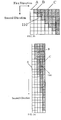
- FIG. 3a is a schematic diagram of a grayscale transition region in an area from 12 to 1 in FIG. 2 ;
- FIG. 3b is a schematic diagram of a grayscale transition region in an area from 1 to 2 in FIG. 2 ;
- FIG. 3c is a schematic diagram of a grayscale transition region in an area from 2 to 3 in FIG. 2 .
- FIG. 4 is another schematic structural view of a display panel to which the image processing method provided by one embodiment of the present disclosure is applied;
- FIG. 5a is a schematic diagram of a grayscale transition region at a boundary of a first triangular sub-area A1;
- FIG. 5b is a schematic diagram of a grayscale transition region at a boundary of a second triangular sub-area A2.
- an edge of the display image region includes a polygonal line segment formed by connection of first line segments 101 and second line segments 102 (the first line segment 101 indicates a line segment extending along the row direction, and the second line segment 102 indicates a line segment extending along the column direction) extending along the row direction and the column direction, and a boundary line between the display image region and the peripheral region here is the polygonal line segment formed by connection of a plurality of first line segments 101 and a plurality of second line segments 102.
- the boundary line between the display image region and the peripheral region is a saw-toothed polygonal line segment, that is, at the micro level (namely in the pixel level), the shape of the microscopic edge of the display image region is a sawtooth shape encircled by the polygonal line segments.
- the position of the grayscale transition region may be determined according to following methods.
- the step S102 may include: forming a virtual rectangular area in the peripheral region by taking adjacent two line segments as adjacent two sides; and determining a quantity and an arrangement mode of transition pixels in the grayscale transition region according to the virtual rectangular area.
- the virtual rectangle formed in the peripheral region by taking adjacent two line segments (e.g., the first line segment 102 and the second line segment 102) as adjacent two sides includes M rows and N columns of pixels, and both M and N are positive integers.
- a virtual rectangle 110 (disposed in elliptical dotted line) includes one row and a plurality of columns of pixels.
- determining a quantity and an arrangement mode of the transition pixels in the grayscale transition region according to the virtual rectangular area includes:
- the grayscale transition region may include one pixel disposed in the virtual rectangular area, namely the grayscale transition region may include one transition pixel.
- the grayscale transition region may include the four transition pixels disposed in the same row.
- adjacent four pixels in the same column of the virtual rectangular area may be transition pixels, namely the grayscale transition region may include the four transition pixels disposed in the same column.
- the transition pixels may include all the pixels in the virtual rectangular area and a portion of pixels in the peripheral region in an extending direction of the grayscale transition region.
- the grayscale transition region may include three pixels disposed in the virtual rectangular area and one pixel adjacent to the virtual rectangular area in a first direction (for instance, the first direction indicates the extending direction of the grayscale transition region), that is, the grayscale transition region may include four transition pixels disposed in the same row.
- the macroscopic edge of the display image region may be a straight line, or the macroscopic edge of the display image region may also be a curved line.
- the specific shape of the display image region is a triangle, a diamond or a polygon
- the case that the macroscopic edge of the display image region is a straight line may occur; and when the specific shape of the display image region is a circle or an ellipse, the case that the macroscopic edge of the display image region is a curved line may occur.
- the macroscopic edge of the display image region comprises a curved line and a straight line at the same time, and the present disclosure is not limited thereto.
- the macroscopic edge of the display image region indicates the boundary of the overall shape of the display image region at the macro level. For instance, if the display image region is round, the macroscopic edge of the display image region is a curved line; and if the boundary of the display image region is a polygon such as a triangle or a diamond, the macroscopic edge of the display image region is a straight line.
- the positions of the grayscale transition regions can be determined according to a following method:
- both the first default included angle ⁇ 1 and the second default included angle ⁇ 2 are acute angles; the first default included angle ⁇ 1 is greater than or equal to 45° and less than 90°, and the second default included angle ⁇ 2 is less than or equal to 45° and greater than 0°.
- the second default included angle ⁇ 2 is usually less than the first default included angle ⁇ 1.
- the second default included angle ⁇ 2 may be 30° and the first default included angle ⁇ 1 may be usually 60°.
- the second default included angle ⁇ 2 may also be equal to the first default included angle ⁇ 1.
- both the second default included angle ⁇ 2 and the first default included angle ⁇ 1 are 45°. No limitation will be given here.
- the display panel includes a display image region A and a peripheral region.
- a first macroscopic edge 100, a second macroscopic edge 110 and a third macroscopic edge 120 are located between the display image region A and the peripheral region.
- the peripheral region includes a background image region C and a grayscale transition region B (not shown in FIG. 2 ) disposed between the display image region A and the background image region C.
- the display image region A may be round.
- the first default included angle may be set to be 60°
- the second default included angle may be set to be 30°.
- the round display image region A can be equally divided into four portions along horizontal and vertical directions, and each portion is a sector with a 90 degree central angle.
- the sector may be divided into three equal parts along the central angle, and the three equal parts include a first sectorial sub-area from a number 12 to a number 1, a second sectorial sub-area from a number 1 to a number 2, and a third sectorial sub-area from a number 2 to a number 3.
- the first macroscopic edge 100 is between the first sectorial sub-area and the peripheral area
- the second macroscopic edge 110 is between the second sectorial sub-area and the peripheral area
- the third macroscopic edge 120 is between the third sectorial sub-area and the peripheral area.
- each of grayscale transition regions B adjacent to the first sectorial sub-area may include a plurality of transition pixels located in one row and adjacent to the first sectorial sub-area in the peripheral region.
- each of the grayscale transition regions B may include 2 to 4 transition pixels located in one row.
- each of grayscale transition regions B adjacent to the second sectorial sub-area may include one transition pixel adjacent to the second sectorial sub-area in the peripheral region.
- each of grayscale transition regions B adjacent to the third sectorial sub-area may include a plurality of transition pixels located in one column and adjacent to the third sectorial sub-area in the peripheral region.
- each of the grayscale transition regions B may include 4 or 5 transition pixels located in one column.
- the positions of the grayscale transition regions can be determined by a following method:
- the second default included angle ⁇ 2 is usually less than the first default included angle ⁇ 1.
- the second default included angle ⁇ 2 may be 30° and the first default included angle ⁇ 1 is generally 60°.
- the second default included angle ⁇ 2 may also be equal to the first default included angle ⁇ 1.
- both the second default included angle ⁇ 2 and the first default included angle ⁇ 1 are 45°.
- both the first default included angle ⁇ 1 and the second default included angle ⁇ 2 may be set to be 45°.
- the pentagonal display image region may be can be equally divided into 5 equal portions along a center and sides, and each portion is an isosceles triangle with a vertex angle of 72°.
- the 5 equal portions are respectively a first triangular sub-area A1, a second triangular sub-area A2, a third triangular sub-area A3, a fourth triangular sub-area A4 and a fifth triangular sub-area A5.
- a normal line direction of the macroscopic edge of the display image region does not coincide with the row direction 109 and the column direction 103 of the pixel array; and at a junction between the third triangular sub-area A3 and the peripheral region, a normal line direction of the macroscopic edge of the display image region coincides with the column direction 103 of the pixel array.
- grayscale transition regions (not shown in FIG. 4 ) are provided at the junctions between the peripheral region and the first triangular sub-area A1, the second triangular sub-area A2, the fourth triangular sub-area A4 and the fifth triangular sub-area A5.
- an included angle ⁇ 1 between a macroscopic edge 200 corresponding to the first triangular sub-area A1 and the column direction 103 of the pixel array is 54°, so the included angle ⁇ 1 is greater than 45°, namely greater than the first default included angle ⁇ 1.
- each of the grayscale transition regions B adjacent to the macroscopic edge 200 may include a plurality of transition pixels located in one row and adjacent to the first triangular sub-area A1 in the peripheral region.
- each of the grayscale transition regions B may include 3 or 4 transition pixels located in one row.
- an included angle ⁇ 2 between a macroscopic edge 210 corresponding to the second triangular sub-area A2 and the column direction 103 of the pixel array is 18°, so the included angle ⁇ 2 is less than 45°, namely less than the second default included angle ⁇ 2.
- each of the grayscale transition regions B adjacent to the macroscopic edge 210 may include a plurality of transition pixels located in one column and adjacent to the second triangular sub-area A2 in the peripheral region.
- each of the grayscale transition regions may include 4 or 5 transition pixels located in one column.
- the display image region is a pentagon as an example.
- the above image processing method provided by the embodiment of the present disclosure does not specifically limit the shape of the display image region.
- included angles are all acute angles.
- the position of the grayscale transition region may be determined according to the shape of the display image region.
- the number of the transition pixels included in each grayscale transition region may be different.
- the number of the transition pixels in each grayscale transition region may be greater than 1. Therefore, the third pixel grayscales of the transition pixels in each grayscale transition region can be adjusted by various methods, so as to achieve an effect of edge blurring and effectively weaken the sawtooth sense at the edge.
- the step S101 may include following steps: determining an extending direction of the grayscale transition region according to the position of the grayscale transition region; and determining the adjacent display pixel adjacent to the grayscale transition region in the display image region in the extending direction of the grayscale transition region.
- the step SI01 may further include: determining an extending direction of the grayscale transition region according to the position of the grayscale transition region; and determining the adjacent background pixel adjacent to the grayscale transition region in the background image region in the extending direction of the grayscale transition region.
- the second pixel grayscale is a grayscale of the adjacent background pixel.
- the extending direction of the grayscale transition region may indicate a direction in which the transition pixels are arranged in the grayscale transition region.
- the extending direction of the grayscale transition region may be the row direction of the pixel array, namely a first direction in FIGS. 3a and 5a .
- the extending direction of the grayscale transition region may be the column direction of the pixel array, namely the second direction in FIGS. 3c and 5b .
- the extending direction of the grayscale transition region may be the row direction of the pixel array (namely the first direction in FIG. 3b ), and may also be the column direction of the pixel array (namely the second direction in FIG. 3b ).
- the number of the adjacent display pixels may be 1.
- the number of the adjacent background pixels may also be 1. Taking a grayscale transition region in a first row shown in FIG. 3a as an example, in the display image region A, the adjacent display pixel is a pixel 10; and in the background image region C, the adjacent background pixel is a pixel 20.
- the first pixel grayscale of the adjacent display pixels indicates an average value of first pixel grayscales of the plurality of adjacent display pixels
- the second pixel grayscale of the adjacent background pixels indicates an average value of second pixel grayscales of the plurality of adjacent background pixels.
- adjusting the third pixel grayscale of the transition pixel according to the first pixel grayscale, the second pixel grayscale and the transition pixel may include: adjusting the third pixel grayscale of the transition pixel according to the first pixel grayscale, the second pixel grayscale, and the arrangement mode and the number of transition pixels in the grayscale transition region, and the like.
- third pixel grayscales of a plurality of transition pixels in the grayscale transition region may be set to be same value.
- the third pixel grayscales of the plurality of transition pixels in the grayscale transition region may be an average value of the first pixel grayscale of the adjacent display pixel and the second pixel grayscale (for instance, the grayscale of the adjacent background pixel).
- the step S105 may include: when the first pixel grayscale of the adjacent display pixel is greater than the second pixel grayscale, in the extending direction of the grayscale transition region, adjusting third pixel grayscales of transition pixels in the grayscale transition region to be gradually decreased in a direction from the display image region to the peripheral region. For instance, in a case of displaying a picture in white-black as shown in FIG.
- the first pixel grayscale of the adjacent display pixel is white (e.g., 255); and in the background image region, the second pixel grayscale of the adjacent background pixel is black (e.g., 0).
- the third pixel grayscales of the transition pixels in the grayscale transition region can be gradually decreased, to gradually reduce the brightness, thereby achieving the effect of edge blurring, and effectively weakening the sense of edge sawteeth.
- the step S105 may include: when the first pixel grayscale of the adjacent display pixel is less than the second pixel grayscale, in the extending direction of the grayscale transition region, adjusting the third pixel grayscales of the transition pixels in the grayscale transition region to be gradually increased in a direction from the display image region to the peripheral region. For instance, in the case of displaying a picture in white-black, in the display image region, the first pixel grayscale of the adjacent display pixel is black; and in the background image region, the second pixel grayscale of the adjacent background pixel is white.
- the third pixel grayscales of the transition pixels in the grayscale transition region can be gradually increased, to gradually increase the brightness, thereby achieving the effect of edge blurring, and effectively weakening the sense of edge sawteeth.
- grayscale change step lengths of the third pixel grayscales of the transition pixels in the grayscale transition region may be same, so as to achieve the optimum effect of edge blurring and effectively weaken the sense of edge sawteeth.
- the first pixel grayscale of the adjacent display pixel 10 is X
- the second pixel grayscale of the adjacent background pixel 20 is 0.
- the third pixel grayscales of four transition pixels in the grayscale transition region B is subjected to grayscale reduction processing with an equal step length, in which the step length is (X-0)/(4+1)(grayscale). For instance, when a value of X is 100, a value of the step length is 20.
- FIG. 6 is a schematic diagram of a grayscale transition region in a first row as shown in FIG. 3a .
- the brightness of the transition pixels in the grayscale transition region is slowly transitioned. Therefore, the local sawtooth sense can be weakened, the overall appearance can be blurred after edge processing, the edge contrast can be reduced, and the effect of reducing the sawtooth sensation can be achieved.
- the step S106 further includes: transmitting grayscales of display pixels in the display image region to the display image region for display.
- the step S106 further includes: transmitting grayscales of the background pixels in the background image region to the background image region for display.
- the grayscales of the display pixels in the display image region includes the first pixel grayscale; and the grayscales of the background pixels in the background image region includes the second pixel grayscale.
- the grayscales of the display pixels in the display image region, the grayscales of the background pixels in the background image region, and the third pixel grayscale can be transmitted to the display panel by a motherboard of the display panel.
- An embodiment of the present disclosure further provides a drive device of a display panel.
- the drive device may be applied to a display panel, e.g., an active organic electroluminescent display panel.
- FIG. 7 is a schematic structural view of a drive device of a display panel provided by an embodiment of the present disclosure.
- the drive device may comprise a data acquisition circuit 701, a memory 702, a processor 703, and a data transmission circuit 704.
- the display panel includes a display image region and a peripheral region; and a pixel array arranged in an array is arranged on the display panel.
- the peripheral region includes grayscale transition regions.
- the grayscale transition regions are adjacent to the display image region.
- the display image region includes a plurality of display pixels arranged along a row direction and a column direction.
- the data acquisition circuit 701 is configured to acquire a first pixel grayscale and a second pixel grayscale.
- the first pixel grayscale is a grayscale of an adjacent display pixel adjacent to a grayscale transition region in the display image region.
- the memory 702 is configured to store a position of the grayscale transition region.
- the processor 703 is configured to, according to the stored position of the grayscale transition region, determine the adjacent display pixel adjacent to the grayscale transition region in the row direction or in the column direction in the display image region, the first pixel grayscale being the grayscale of the adjacent display pixel; determine a transition pixel in the grayscale transition region; and adjust a third pixel grayscale of the transition pixel in the grayscale transition region according to the first pixel grayscale, the second pixel grayscale and the transition pixel.
- the third pixel grayscale is between the first pixel grayscale of the adjacent display pixel and the second pixel grayscale.
- the data transmission circuit 704 is configured to transmit the third pixel grayscale to the display panel for display.
- the memory 702 may also be configured to store the first pixel grayscale and/or the second pixel grayscale.
- the data transmission circuit 704 is also configured to transmit grayscales of display pixels in the display image region to the display image region for display.
- the data transmission circuit 704 is also configured to transmit grayscales of the background pixels in the background image region to the background image region for display.
- the background pixels can be arranged in an array along the row direction and the column direction.
- the processor 703 is also configured to determine an adjacent background pixel adjacent to the grayscale transition region in the row direction or in the column direction in the background image region according to the position of the grayscale transition region, the second pixel grayscale is a grayscale of the adjacent background pixel.
- a shape of the display image region includes a non-rectangular shape (e.g., round and so on).
- An edge of the display image region includes a polygonal line segment formed by connection of line segments extending along the row direction and the column direction. The row direction and the column direction may be perpendicular to each other.
- a step of determining the transition pixel in the grayscale transition region includes: forming a virtual rectangular area in the peripheral region by taking adjacent two line segments as adjacent two sides; and determining a quantity and an arrangement mode of transition pixels in the grayscale transition region according to the virtual rectangular area.
- a step of determining the quantity and the arrangement mode of transition pixels in the grayscale transition region according to the virtual rectangular area, performed by the processor includes:
- the detailed description on the step of determining the transition pixel in the grayscale transition region performed by the processor 703 may refer to relevant description in the embodiment of the image processing method, and the repeated descriptions will be omitted here.
- each grayscale transition region may include a plurality of transition pixels located in one row and adjacent to the display image region in the peripheral region; when the included angle between the macroscopic edge of the display image region and the column direction of the pixel array is greater than 0° and less than a second default included angle, each grayscale transition region may include a plurality of transition pixels located in one column and adjacent to the display image region in the peripheral region; when the included angle between the macroscopic edge of the display image region and the column direction of the pixel array is greater than or equal to the second default included angle and less than or equal to the first default included angle, each grayscale transition region may include one transition pixel adjacent to the display image region
- each grayscale transition region may include a plurality of transition pixels located in one row and adjacent to the display image region in the peripheral region; when the included angle between the tangential line of the macroscopic edge of the display image region and the column direction of the pixel array is greater than 0° and less than the second default included angle, each grayscale transition region may include a plurality of transition pixels located in one column and adjacent to the display image region in the peripheral region; and when the included angle between the tangential line of the macroscopic edge of the display image region and the column direction of the pixel array is greater than or equal to the second default included angle and less than or equal to the first default included angle,
- the display image region may be round, and in this case, the first default included angle may be 60° and the second default included angle may be 30°.
- the display image region may be pentagonal, and in this case, the first default included angle and the second default included angle both may be 45°.
- the processor 703 is configured to: in the extending direction of the grayscale transition region, adjust third pixel grayscales of transition pixel in the grayscale transition region to be gradually decreased in a direction from the display image region to the peripheral region.
- the processor 703 is configured to: in the extending direction of the grayscale transition region, adjust third pixel grayscales of transition pixel in the grayscale transition region to be gradually increased in a direction from the display image region to the peripheral region.
- grayscale change step lengths of the third pixel grayscales of the transition pixels in the grayscale transition region may be same.
- FIG. 8 is a schematic structural view of another drive device of a display panel provided by an embodiment of the present disclosure.
- the drive device may be applied to a display panel, e.g., an active organic electroluminescent display panel.
- the drive device may include a memory 810 and a processor 820.
- the memory 810 is configured to store non-transitory computer readable instructions.
- the processor 820 is configured to execute the non-transitory computer readable instructions. When the non-transitory computer readable instructions are execute by the processor, one or more steps in the image processing method provided by any one of the above embodiments can be performed.
- the memory 810 and the processor 820 may be connected with each other through a bus system and/or a connecting mechanism (not shown) in other forms.
- the processor 820 may be a central processing unit (CPU) or other forms of processing units having data processing capabilities and/or program execution capabilities, such as a graphics processing unit (GPU), a field-programmable gate array (FPGA), a tensor processing unit (TPU), or the like.
- the central processing unit (CPU) may be an X86, ARM architecture, or the like.
- the processor 820 may control other components in the drive device to perform desired functions.
- the storage 810 may comprise an arbitrary combination of one or more computer program products.
- the computer program products may comprise various forms of computer-readable storage media, such as volatile memory and/or non-volatile memory.
- the volatile memory may comprise, for example, a random access memory (RAM) and/or a cache or the like.
- the non-volatile memory may comprise, for example, a read only memory (ROM), a hard disk, an erasable programmable read only memory (EPROM), a portable compact disc-read only memory (CD-ROM), a USB memory, a flash memory, and the like.
- One or more computer programs may be stored on the computer-readable storage medium and the processor 820 may execute the non-transitory computer-readable instructions to implement various functions of the drive device.
- Various applications, various data, various data used and/or generated by the applications, and the like may also be stored in the computer-readable storage medium.
- FIG. 9 is a schematic block diagram of a display panel provided by an embodiment of the present disclosure.
- the display panel 500 may comprise a drive device 520 provided by any one of the foregoing embodiments of the present disclosure and a pixel array 510.
- the pixel array 510 is arranged in an array, and the drive device 520 is configured to drive the pixel array 510 to display.
- the display panel can reduce the brightness and the contrast of the edge between the display image region and the peripheral region, thereby effectively ameliorating the problem of edge sawteeth, improving the visual effect of the display panel, and enhancing customer experience.
- the display panel 500 may be an active organic electroluminescent display panel.
- the display panel 500 may be applied to a mobile phone, a tablet, a television, a monitor, a notebook computer, a digital photo frame, a navigator, or any products or components having a display function.
- FIG. 10 is a schematic block diagram of a wearable device provided by an embodiment of the present disclosure.
- the wearable device 600 provided by the embodiment of the present disclosure may comprise the display panel 500 provided by an embodiment of the present disclosure. Therefore, the wearable device 600 can reduce the brightness and the contrast of the edge between the display image region and the peripheral region, thereby effectively ameliorating the problem of edge sawteeth, improving the visual effect of the display panel, and enhancing customer experience.
- the wearable device 600 may be a smart watch, and a display image region of the smart watch may be round, elliptical, etc. But the present disclosure is not limited thereto, the wearable device 600 may also be a smart bracelet, smart eyeglasses, and the like, which is not limited by the embodiments of the present disclosure.
- the embodiments of the present disclosure can be implemented by hardware, or may also be implemented by means of software plus a necessary general hardware platform.
- the technical solution of the embodiments of the present disclosure can be embodied in a form of a software product, and the software product may be stored in a non-volatile storage medium (which may be a CD-ROM, a USB flash disk, a mobile hard disk, etc.) and includes a number of instructions which are configured to allow a computer device (which may be a personal computer, a server, a network device, etc.) to perform the methods of respective embodiments of the present disclosure.
- a non-volatile storage medium which may be a CD-ROM, a USB flash disk, a mobile hard disk, etc.
- a computer device which may be a personal computer, a server, a network device, etc.
- modules in the device provided by the embodiment can be distributed in the device provided by the embodiment according to the description of the embodiment, and can also be correspondingly changed and disposed in one or more devices different from the embodiment.
- the modules of the above embodiments can be combined into one module and can also be further split into a plurality of sub-modules.
- An image processing method of a display panel, a drive device, a display panel and a wearable device can determine the position of the grayscale transition region according to the shape of the display image region, and can adjust the third pixel grayscale of the transition pixel in the grayscale transition region according to the position of the grayscale transition region, the first pixel grayscale of the adjacent display pixel adjacent to the grayscale transition region in the display image region, and the second pixel grayscale to make the third pixel grayscale be between the first pixel grayscale and the second pixel grayscale, thereby reducing the brightness and the contrast of the edge between the display image region and the peripheral region, effectively ameliorating the problem of edge sawteeth, and enhancing customer experience.
Landscapes
- Engineering & Computer Science (AREA)
- Theoretical Computer Science (AREA)
- Computer Hardware Design (AREA)
- Physics & Mathematics (AREA)
- General Physics & Mathematics (AREA)
- Human Computer Interaction (AREA)
- General Engineering & Computer Science (AREA)
- Control Of Indicators Other Than Cathode Ray Tubes (AREA)
- Electroluminescent Light Sources (AREA)
- Control Of El Displays (AREA)
Applications Claiming Priority (2)
| Application Number | Priority Date | Filing Date | Title |
|---|---|---|---|
| CN201710632881.2A CN107450878B (zh) | 2017-07-28 | 2017-07-28 | Amoled的图像处理方法、驱动芯片及可穿戴设备 |
| PCT/CN2018/087734 WO2019019782A1 (fr) | 2017-07-28 | 2018-05-22 | Procédé de traitement d'image, dispositif de pilotage, panneau d'affichage et dispositif vestimentaire |
Publications (3)
| Publication Number | Publication Date |
|---|---|
| EP3660657A1 true EP3660657A1 (fr) | 2020-06-03 |
| EP3660657A4 EP3660657A4 (fr) | 2021-05-05 |
| EP3660657B1 EP3660657B1 (fr) | 2025-07-02 |
Family
ID=60490501
Family Applications (1)
| Application Number | Title | Priority Date | Filing Date |
|---|---|---|---|
| EP18833378.5A Active EP3660657B1 (fr) | 2017-07-28 | 2018-05-22 | Procédé de traitement d'image, dispositif de pilotage, panneau d'affichage et dispositif vestimentaire |
Country Status (4)
| Country | Link |
|---|---|
| US (1) | US11488511B2 (fr) |
| EP (1) | EP3660657B1 (fr) |
| CN (1) | CN107450878B (fr) |
| WO (1) | WO2019019782A1 (fr) |
Cited By (1)
| Publication number | Priority date | Publication date | Assignee | Title |
|---|---|---|---|---|
| EP4375981A4 (fr) * | 2021-07-19 | 2025-01-01 | Tcl China Star Optoelectronics Technology Co., Ltd. | Procédé et appareil de compensation d'affichage, et panneau d'affichage |
Families Citing this family (16)
| Publication number | Priority date | Publication date | Assignee | Title |
|---|---|---|---|---|
| CN107450878B (zh) * | 2017-07-28 | 2019-11-05 | 京东方科技集团股份有限公司 | Amoled的图像处理方法、驱动芯片及可穿戴设备 |
| CN108198534A (zh) * | 2018-01-12 | 2018-06-22 | 京东方科技集团股份有限公司 | 显示方法、显示优化装置、以及显示装置 |
| CN108196811B (zh) * | 2018-01-15 | 2021-08-10 | 惠州Tcl移动通信有限公司 | 一种图片清晰度处理方法、移动终端及存储介质 |
| CN108492773B (zh) * | 2018-03-30 | 2020-09-04 | 武汉华星光电半导体显示技术有限公司 | 一种图像显示方法、异形显示设备及具有存储功能的装置 |
| CN109408022B (zh) * | 2018-10-31 | 2026-03-31 | 北京小米移动软件有限公司 | 显示方法、装置、终端及存储介质 |
| US11127356B2 (en) | 2019-01-04 | 2021-09-21 | Chengdu Boe Optoelectronics Technology Co., Ltd. | Method for compensating brightness unevenness of a display device and related display device |
| CN109859709A (zh) * | 2019-02-12 | 2019-06-07 | 南京中电熊猫平板显示科技有限公司 | 一种异形显示装置 |
| CN110211534B (zh) * | 2019-05-20 | 2021-02-23 | 武汉华星光电半导体显示技术有限公司 | 图像显示方法、装置、控制器及存储介质 |
| CN112308868B (zh) * | 2019-07-26 | 2024-11-12 | 腾讯科技(深圳)有限公司 | 一种图像边缘锯齿点确定方法、装置、设备及存储介质 |
| CN110428411B (zh) * | 2019-07-31 | 2022-08-30 | 武汉精立电子技术有限公司 | 一种基于二次曝光的背光板检测方法及系统 |
| CN114822428B (zh) * | 2021-01-29 | 2023-11-21 | 奇景光电股份有限公司 | 显示面板的驱动电路及其操作方法 |
| CN114512103B (zh) * | 2022-04-19 | 2022-07-12 | 惠科股份有限公司 | 背光模组及显示装置 |
| TWI817668B (zh) * | 2022-08-22 | 2023-10-01 | 大陸商北京集創北方科技股份有限公司 | Oled顯示器之邊緣鋸齒顯示補償方法、驅動晶片及oled顯示裝置 |
| CN115188314B (zh) * | 2022-09-08 | 2023-01-31 | 惠科股份有限公司 | 异形屏的显示电路及显示设备 |
| CN115810325A (zh) * | 2022-12-16 | 2023-03-17 | 信利(仁寿)高端显示科技有限公司 | 一种异形屏像素光透过率调整方法及异形屏 |
| CN117036206B (zh) * | 2023-10-10 | 2024-03-26 | 荣耀终端有限公司 | 一种确定图像锯齿化程度的方法及相关电子设备 |
Family Cites Families (14)
| Publication number | Priority date | Publication date | Assignee | Title |
|---|---|---|---|---|
| US6731257B2 (en) * | 2001-01-22 | 2004-05-04 | Brillian Corporation | Image quality improvement for liquid crystal displays |
| JP5233920B2 (ja) * | 2009-09-01 | 2013-07-10 | セイコーエプソン株式会社 | 映像処理回路、その処理方法、液晶表示装置および電子機器 |
| EP2766852A1 (fr) | 2011-10-13 | 2014-08-20 | Pioneer Hi-Bred International | Détection automatique de pixels d'objet pour une analyse hyperspectrale |
| WO2014024691A1 (fr) * | 2012-08-07 | 2014-02-13 | シャープ株式会社 | Dispositif de traitement d'image, procédé de traitement d'image, programme de traitement d'image et dispositif d'affichage d'image |
| CN104200427B (zh) * | 2014-09-17 | 2017-12-15 | 厦门美图之家科技有限公司 | 一种消除图像边缘锯齿的方法 |
| CN104599625B (zh) | 2015-03-02 | 2017-06-06 | 京东方科技集团股份有限公司 | 边界判定方法和装置、显示驱动方法和装置 |
| CN106652899B (zh) * | 2015-10-29 | 2019-03-12 | 上海和辉光电有限公司 | 显示装置及显示面板的图像显示修正方法 |
| CN106886380B (zh) * | 2015-12-16 | 2020-01-14 | 上海和辉光电有限公司 | 显示装置、图像数据处理装置及方法 |
| US10643577B2 (en) * | 2015-12-22 | 2020-05-05 | Sharp Kabushiki Kaisha | Display device |
| CN105741774B (zh) * | 2016-01-28 | 2018-03-20 | 京东方科技集团股份有限公司 | 一种图像处理方法及其装置、显示装置 |
| CN105511152A (zh) * | 2016-02-02 | 2016-04-20 | 京东方科技集团股份有限公司 | 显示基板、显示面板和显示装置 |
| US10283062B2 (en) * | 2016-08-04 | 2019-05-07 | Apple Inc. | Display with pixel dimming for curved edges |
| CN106530993B (zh) * | 2016-12-28 | 2019-04-16 | 上海天马微电子有限公司 | 一种显示面板和显示装置 |
| CN107450878B (zh) | 2017-07-28 | 2019-11-05 | 京东方科技集团股份有限公司 | Amoled的图像处理方法、驱动芯片及可穿戴设备 |
-
2017
- 2017-07-28 CN CN201710632881.2A patent/CN107450878B/zh active Active
-
2018
- 2018-05-22 WO PCT/CN2018/087734 patent/WO2019019782A1/fr not_active Ceased
- 2018-05-22 EP EP18833378.5A patent/EP3660657B1/fr active Active
- 2018-05-22 US US16/320,390 patent/US11488511B2/en active Active
Cited By (1)
| Publication number | Priority date | Publication date | Assignee | Title |
|---|---|---|---|---|
| EP4375981A4 (fr) * | 2021-07-19 | 2025-01-01 | Tcl China Star Optoelectronics Technology Co., Ltd. | Procédé et appareil de compensation d'affichage, et panneau d'affichage |
Also Published As
| Publication number | Publication date |
|---|---|
| CN107450878B (zh) | 2019-11-05 |
| US11488511B2 (en) | 2022-11-01 |
| CN107450878A (zh) | 2017-12-08 |
| EP3660657B1 (fr) | 2025-07-02 |
| US20210335189A1 (en) | 2021-10-28 |
| EP3660657A4 (fr) | 2021-05-05 |
| WO2019019782A1 (fr) | 2019-01-31 |
Similar Documents
| Publication | Publication Date | Title |
|---|---|---|
| EP3660657B1 (fr) | Procédé de traitement d'image, dispositif de pilotage, panneau d'affichage et dispositif vestimentaire | |
| EP3667608B1 (fr) | Procédé d'affichage d'image, système d'affichage, et support d'informations lisible par ordinateur | |
| CN205281989U (zh) | 一种显示面板、显示装置 | |
| EP3850585B1 (fr) | Rendu fovéal adaptatif en vol | |
| US20180166003A1 (en) | Image processing method, apparatus, and display device | |
| US8775965B1 (en) | Immersive mode for a web browser | |
| CN109791431B (zh) | 视点渲染 | |
| US20160321986A1 (en) | Control device, display device, control method and program product | |
| US11474401B2 (en) | Display panel and fabrication method thereof, and display apparatus | |
| US10297234B2 (en) | Curved virtual display surface for displaying digital objects | |
| CN111476852B (zh) | 阅读器刷新方法、计算设备及计算机存储介质 | |
| CN104616631A (zh) | 一种应用于mva广视角液晶屏的显示方法及装置 | |
| CN107277419A (zh) | 一种显示装置及其显示方法 | |
| CN104094167A (zh) | 具有基本白屏关闭状态的电子显示投影组件 | |
| WO2020192493A1 (fr) | Procédé de commande d'affichage, support de stockage, appareil de commande d'affichage, et appareil d'affichage | |
| CN105467603B (zh) | 一种立体显示装置 | |
| US11158237B2 (en) | Driving method for display panel, and display device based on viewing distance | |
| KR102592143B1 (ko) | 디스플레이 장치 및 그의 구동 방법 | |
| US10838269B2 (en) | Curved display panel and display device | |
| WO2021102772A1 (fr) | Procédés et appareil pour lisser des parties de bord d'un dispositif d'affichage de forme irrégulière | |
| JP2002287150A (ja) | 液晶装置および電子機器 | |
| CN119105215B (zh) | 显示面板和显示装置 | |
| CN114815406A (zh) | 一种阵列基板、液晶显示面板和显示装置 | |
| US11513346B2 (en) | Method and apparatus for controlling virtual reality display device | |
| CN112988294B (zh) | 一种rh850液晶仪表虚拟指针优化方法和装置 |
Legal Events
| Date | Code | Title | Description |
|---|---|---|---|
| STAA | Information on the status of an ep patent application or granted ep patent |
Free format text: STATUS: UNKNOWN |
|
| STAA | Information on the status of an ep patent application or granted ep patent |
Free format text: STATUS: THE INTERNATIONAL PUBLICATION HAS BEEN MADE |
|
| PUAI | Public reference made under article 153(3) epc to a published international application that has entered the european phase |
Free format text: ORIGINAL CODE: 0009012 |
|
| STAA | Information on the status of an ep patent application or granted ep patent |
Free format text: STATUS: REQUEST FOR EXAMINATION WAS MADE |
|
| 17P | Request for examination filed |
Effective date: 20190131 |
|
| AK | Designated contracting states |
Kind code of ref document: A1 Designated state(s): AL AT BE BG CH CY CZ DE DK EE ES FI FR GB GR HR HU IE IS IT LI LT LU LV MC MK MT NL NO PL PT RO RS SE SI SK SM TR |
|
| AX | Request for extension of the european patent |
Extension state: BA ME |
|
| DAV | Request for validation of the european patent (deleted) | ||
| DAX | Request for extension of the european patent (deleted) | ||
| A4 | Supplementary search report drawn up and despatched |
Effective date: 20210406 |
|
| RIC1 | Information provided on ipc code assigned before grant |
Ipc: G06F 3/147 20060101AFI20210329BHEP Ipc: G09G 5/02 20060101ALI20210329BHEP Ipc: G09G 3/20 20060101ALI20210329BHEP Ipc: G06T 5/00 20060101ALI20210329BHEP Ipc: G06F 1/16 20060101ALI20210329BHEP Ipc: G09G 3/3208 20160101ALI20210329BHEP Ipc: G06T 5/20 20060101ALI20210329BHEP |
|
| STAA | Information on the status of an ep patent application or granted ep patent |
Free format text: STATUS: EXAMINATION IS IN PROGRESS |
|
| 17Q | First examination report despatched |
Effective date: 20230201 |
|
| GRAP | Despatch of communication of intention to grant a patent |
Free format text: ORIGINAL CODE: EPIDOSNIGR1 |
|
| STAA | Information on the status of an ep patent application or granted ep patent |
Free format text: STATUS: GRANT OF PATENT IS INTENDED |
|
| INTG | Intention to grant announced |
Effective date: 20250210 |
|
| GRAS | Grant fee paid |
Free format text: ORIGINAL CODE: EPIDOSNIGR3 |
|
| GRAA | (expected) grant |
Free format text: ORIGINAL CODE: 0009210 |
|
| STAA | Information on the status of an ep patent application or granted ep patent |
Free format text: STATUS: THE PATENT HAS BEEN GRANTED |
|
| AK | Designated contracting states |
Kind code of ref document: B1 Designated state(s): AL AT BE BG CH CY CZ DE DK EE ES FI FR GB GR HR HU IE IS IT LI LT LU LV MC MK MT NL NO PL PT RO RS SE SI SK SM TR |
|
| REG | Reference to a national code |
Ref country code: GB Ref legal event code: FG4D |
|
| REG | Reference to a national code |
Ref country code: CH Ref legal event code: EP |
|
| REG | Reference to a national code |
Ref country code: DE Ref legal event code: R096 Ref document number: 602018083264 Country of ref document: DE |
|
| REG | Reference to a national code |
Ref country code: IE Ref legal event code: FG4D |
|
| REG | Reference to a national code |
Ref country code: NL Ref legal event code: MP Effective date: 20250702 |
|
| PG25 | Lapsed in a contracting state [announced via postgrant information from national office to epo] |
Ref country code: PT Free format text: LAPSE BECAUSE OF FAILURE TO SUBMIT A TRANSLATION OF THE DESCRIPTION OR TO PAY THE FEE WITHIN THE PRESCRIBED TIME-LIMIT Effective date: 20251103 |
|
| PG25 | Lapsed in a contracting state [announced via postgrant information from national office to epo] |
Ref country code: NL Free format text: LAPSE BECAUSE OF FAILURE TO SUBMIT A TRANSLATION OF THE DESCRIPTION OR TO PAY THE FEE WITHIN THE PRESCRIBED TIME-LIMIT Effective date: 20250702 |
|
| REG | Reference to a national code |
Ref country code: AT Ref legal event code: MK05 Ref document number: 1809996 Country of ref document: AT Kind code of ref document: T Effective date: 20250702 |
|
| PG25 | Lapsed in a contracting state [announced via postgrant information from national office to epo] |
Ref country code: IS Free format text: LAPSE BECAUSE OF FAILURE TO SUBMIT A TRANSLATION OF THE DESCRIPTION OR TO PAY THE FEE WITHIN THE PRESCRIBED TIME-LIMIT Effective date: 20251102 |
|
| PG25 | Lapsed in a contracting state [announced via postgrant information from national office to epo] |
Ref country code: NO Free format text: LAPSE BECAUSE OF FAILURE TO SUBMIT A TRANSLATION OF THE DESCRIPTION OR TO PAY THE FEE WITHIN THE PRESCRIBED TIME-LIMIT Effective date: 20251002 |
|
| REG | Reference to a national code |
Ref country code: LT Ref legal event code: MG9D |
|
| PG25 | Lapsed in a contracting state [announced via postgrant information from national office to epo] |
Ref country code: AT Free format text: LAPSE BECAUSE OF FAILURE TO SUBMIT A TRANSLATION OF THE DESCRIPTION OR TO PAY THE FEE WITHIN THE PRESCRIBED TIME-LIMIT Effective date: 20250702 |
|
| PG25 | Lapsed in a contracting state [announced via postgrant information from national office to epo] |
Ref country code: FI Free format text: LAPSE BECAUSE OF FAILURE TO SUBMIT A TRANSLATION OF THE DESCRIPTION OR TO PAY THE FEE WITHIN THE PRESCRIBED TIME-LIMIT Effective date: 20250702 |
|
| PG25 | Lapsed in a contracting state [announced via postgrant information from national office to epo] |
Ref country code: HR Free format text: LAPSE BECAUSE OF FAILURE TO SUBMIT A TRANSLATION OF THE DESCRIPTION OR TO PAY THE FEE WITHIN THE PRESCRIBED TIME-LIMIT Effective date: 20250702 |
|
| PG25 | Lapsed in a contracting state [announced via postgrant information from national office to epo] |
Ref country code: GR Free format text: LAPSE BECAUSE OF FAILURE TO SUBMIT A TRANSLATION OF THE DESCRIPTION OR TO PAY THE FEE WITHIN THE PRESCRIBED TIME-LIMIT Effective date: 20251003 |
|
| PG25 | Lapsed in a contracting state [announced via postgrant information from national office to epo] |
Ref country code: SE Free format text: LAPSE BECAUSE OF FAILURE TO SUBMIT A TRANSLATION OF THE DESCRIPTION OR TO PAY THE FEE WITHIN THE PRESCRIBED TIME-LIMIT Effective date: 20250702 Ref country code: CZ Free format text: LAPSE BECAUSE OF FAILURE TO SUBMIT A TRANSLATION OF THE DESCRIPTION OR TO PAY THE FEE WITHIN THE PRESCRIBED TIME-LIMIT Effective date: 20250702 |
|
| PG25 | Lapsed in a contracting state [announced via postgrant information from national office to epo] |
Ref country code: LV Free format text: LAPSE BECAUSE OF FAILURE TO SUBMIT A TRANSLATION OF THE DESCRIPTION OR TO PAY THE FEE WITHIN THE PRESCRIBED TIME-LIMIT Effective date: 20250702 |
|
| PG25 | Lapsed in a contracting state [announced via postgrant information from national office to epo] |
Ref country code: PL Free format text: LAPSE BECAUSE OF FAILURE TO SUBMIT A TRANSLATION OF THE DESCRIPTION OR TO PAY THE FEE WITHIN THE PRESCRIBED TIME-LIMIT Effective date: 20250702 Ref country code: BG Free format text: LAPSE BECAUSE OF FAILURE TO SUBMIT A TRANSLATION OF THE DESCRIPTION OR TO PAY THE FEE WITHIN THE PRESCRIBED TIME-LIMIT Effective date: 20250702 |
|
| PG25 | Lapsed in a contracting state [announced via postgrant information from national office to epo] |
Ref country code: RS Free format text: LAPSE BECAUSE OF FAILURE TO SUBMIT A TRANSLATION OF THE DESCRIPTION OR TO PAY THE FEE WITHIN THE PRESCRIBED TIME-LIMIT Effective date: 20251002 |
|
| PG25 | Lapsed in a contracting state [announced via postgrant information from national office to epo] |
Ref country code: ES Free format text: LAPSE BECAUSE OF FAILURE TO SUBMIT A TRANSLATION OF THE DESCRIPTION OR TO PAY THE FEE WITHIN THE PRESCRIBED TIME-LIMIT Effective date: 20250702 |
|
| PG25 | Lapsed in a contracting state [announced via postgrant information from national office to epo] |
Ref country code: SM Free format text: LAPSE BECAUSE OF FAILURE TO SUBMIT A TRANSLATION OF THE DESCRIPTION OR TO PAY THE FEE WITHIN THE PRESCRIBED TIME-LIMIT Effective date: 20250702 |
|
| PG25 | Lapsed in a contracting state [announced via postgrant information from national office to epo] |
Ref country code: DK Free format text: LAPSE BECAUSE OF FAILURE TO SUBMIT A TRANSLATION OF THE DESCRIPTION OR TO PAY THE FEE WITHIN THE PRESCRIBED TIME-LIMIT Effective date: 20250702 |
|
| PG25 | Lapsed in a contracting state [announced via postgrant information from national office to epo] |
Ref country code: IT Free format text: LAPSE BECAUSE OF FAILURE TO SUBMIT A TRANSLATION OF THE DESCRIPTION OR TO PAY THE FEE WITHIN THE PRESCRIBED TIME-LIMIT Effective date: 20250702 |
|
| PG25 | Lapsed in a contracting state [announced via postgrant information from national office to epo] |
Ref country code: SK Free format text: LAPSE BECAUSE OF FAILURE TO SUBMIT A TRANSLATION OF THE DESCRIPTION OR TO PAY THE FEE WITHIN THE PRESCRIBED TIME-LIMIT Effective date: 20250702 Ref country code: EE Free format text: LAPSE BECAUSE OF FAILURE TO SUBMIT A TRANSLATION OF THE DESCRIPTION OR TO PAY THE FEE WITHIN THE PRESCRIBED TIME-LIMIT Effective date: 20250702 |