EP3660864B1 - Standard für mobile ausrüstung zur messung der strukturellen verformung eines kernbrennstabbündels - Google Patents
Standard für mobile ausrüstung zur messung der strukturellen verformung eines kernbrennstabbündels Download PDFInfo
- Publication number
- EP3660864B1 EP3660864B1 EP17919393.3A EP17919393A EP3660864B1 EP 3660864 B1 EP3660864 B1 EP 3660864B1 EP 17919393 A EP17919393 A EP 17919393A EP 3660864 B1 EP3660864 B1 EP 3660864B1
- Authority
- EP
- European Patent Office
- Prior art keywords
- standard
- nuclear fuel
- fuel assembly
- standard member
- protective cover
- Prior art date
- Legal status (The legal status is an assumption and is not a legal conclusion. Google has not performed a legal analysis and makes no representation as to the accuracy of the status listed.)
- Active
Links
Images



Classifications
-
- G—PHYSICS
- G21—NUCLEAR PHYSICS; NUCLEAR ENGINEERING
- G21C—NUCLEAR REACTORS
- G21C3/00—Reactor fuel elements and their assemblies; Selection of substances for use as reactor fuel elements
- G21C3/30—Assemblies of a number of fuel elements in the form of a rigid unit
- G21C3/32—Bundles of parallel pin-, rod-, or tube-shaped fuel elements
- G21C3/334—Assembling, maintenance or repair of the bundles
-
- G—PHYSICS
- G01—MEASURING; TESTING
- G01B—MEASURING LENGTH, THICKNESS OR SIMILAR LINEAR DIMENSIONS; MEASURING ANGLES; MEASURING AREAS; MEASURING IRREGULARITIES OF SURFACES OR CONTOURS
- G01B11/00—Measuring arrangements characterised by the use of optical techniques
- G01B11/16—Measuring arrangements characterised by the use of optical techniques for measuring the deformation in a solid, e.g. optical strain gauge
-
- G—PHYSICS
- G21—NUCLEAR PHYSICS; NUCLEAR ENGINEERING
- G21C—NUCLEAR REACTORS
- G21C17/00—Monitoring; Testing ; Maintaining
- G21C17/06—Devices or arrangements for monitoring or testing fuel or fuel elements outside the reactor core, e.g. for burn-up, for contamination
-
- G—PHYSICS
- G21—NUCLEAR PHYSICS; NUCLEAR ENGINEERING
- G21F—PROTECTION AGAINST X-RADIATION, GAMMA RADIATION, CORPUSCULAR RADIATION OR PARTICLE BOMBARDMENT; TREATING RADIOACTIVELY CONTAMINATED MATERIAL; DECONTAMINATION ARRANGEMENTS THEREFOR
- G21F5/00—Transportable or portable shielded containers
- G21F5/005—Containers for solid radioactive wastes, e.g. for ultimate disposal
- G21F5/008—Containers for fuel elements
- G21F5/012—Fuel element racks in the containers
-
- G—PHYSICS
- G21—NUCLEAR PHYSICS; NUCLEAR ENGINEERING
- G21F—PROTECTION AGAINST X-RADIATION, GAMMA RADIATION, CORPUSCULAR RADIATION OR PARTICLE BOMBARDMENT; TREATING RADIOACTIVELY CONTAMINATED MATERIAL; DECONTAMINATION ARRANGEMENTS THEREFOR
- G21F5/00—Transportable or portable shielded containers
- G21F5/06—Details of, or accessories to, the containers
-
- Y—GENERAL TAGGING OF NEW TECHNOLOGICAL DEVELOPMENTS; GENERAL TAGGING OF CROSS-SECTIONAL TECHNOLOGIES SPANNING OVER SEVERAL SECTIONS OF THE IPC; TECHNICAL SUBJECTS COVERED BY FORMER USPC CROSS-REFERENCE ART COLLECTIONS [XRACs] AND DIGESTS
- Y02—TECHNOLOGIES OR APPLICATIONS FOR MITIGATION OR ADAPTATION AGAINST CLIMATE CHANGE
- Y02E—REDUCTION OF GREENHOUSE GAS [GHG] EMISSIONS, RELATED TO ENERGY GENERATION, TRANSMISSION OR DISTRIBUTION
- Y02E30/00—Energy generation of nuclear origin
- Y02E30/30—Nuclear fission reactors
Definitions
- the present invention relates to a standard for mobile equipment for measuring structural deformation of a nuclear fuel assembly and, more particularly, to a standard for mobile equipment for measuring structural deformation of a nuclear fuel assembly, which enhances accuracy of measuring the structural deformation of the nuclear fuel assembly through calibration work of a scanner using a standard member corresponding to a nuclear fuel assembly standard specification.
- a nuclear power plant is configured to heat a primary coolant using energy generated during nuclear fission by using nuclear fuel inside a nuclear reactor, to transfer heated energy of the primary coolant to a steam generator, thereby transferring the energy to a secondary coolant and generating steam in the steam generator, to rotate a turbine using the steam, and to convert rotational energy of the turbine into electric power by a generator.
- Energy sources for the nuclear fission are provided by the nuclear fuel.
- the nuclear fuel arranged inside the nuclear reactor is composed of nuclear fuel assemblies 10, with each nuclear fuel assembly as a unit, as shown in FIG. 1 , and the nuclear fuel assembly 10 includes a framework composed of a top nozzle 11, a bottom nozzle 12, and spacer grid assemblies 13; and nuclear fuel rods 20 each inserted into the spacer grid assemblies 13 and supported by springs and dimples provided in the spacer grid assemblies 13.
- each of the nuclear fuel rods 20 is composed of a plurality of uranium pellets 21 and a zirconium alloy cladding tube 22 provided in the form of a long bar for protecting the uranium and preventing radiation leakage.
- a process of manufacturing the nuclear fuel assembly 10 is completed by inspecting gaps, warpage, full length, dimensions, and the like between the nuclear fuel rods 20.
- the nuclear fuel assembly 10 the manufacturing process of which is completed as described above, is not directly introduced into the nuclear reactor but is inspected to determine whether the nuclear fuel assembly 10 is structurally deformed.
- the collision with the neighboring nuclear fuel assemblies 10 may occur, and thus the cladding tube 22 of the nuclear fuel rod 20 may be damaged.
- the cladding tube 22 of the nuclear fuel rod 20 is damaged, radioactivity may be excessively leaked from the nuclear fuel, thereby intensifying contamination of the primary coolant.
- the nuclear fuel rods 20 may be dropped out and moved inside the nuclear reactor, thereby causing a highly risky situation.
- the nuclear fuel assembly 10 is required to have a high degree of reliability with respect to quality thereof, work of inspecting the structural deformation of the nuclear fuel assembly 10 is obviously a very important task.
- equipment for measuring a structure of the nuclear fuel assembly 10 has been provided but has been limited to measurement of a structure of the spacer grid assemblies 13 of the nuclear fuel assembly 10, thereby having a problem of being limited in measuring the nuclear fuel assembly 10 as a whole.
- US 2012/008729 discloses a shipping container for nuclear fuel assemblies.
- the shipping container has a lid frame.
- US 4,175,000 discloses a method of disassembling a nuclear reactor fuel element without destroying the individual fuel pins
- an object of the present invention is to provide a standard for mobile equipment for measuring structural deformation of a nuclear fuel assembly, wherein a standard member corresponding to a nuclear fuel assembly standard specification is provided in the measuring equipment in order to allow the calibration work of a scanner to be performed.
- the present invention provides a standard device for mobile equipment for measuring structural deformation of a nuclear fuel assembly, as defined in claim 1.
- the fixing frame may include: a protective cover provided with an accommodating groove configured to accommodate the standard member and with a fastening means configured to prevent the standard member accommodated in the accommodating groove from being removed; a lower support provided below the protective cover and fixed to the container; and an upper support installed between the protective cover and the lower support and configured to fix the protective cover to the lower support.
- a plurality of buffer members may be further provided between both side parts of the upper support and the lower support, in a longitudinal direction of the lower support.
- through holes may be provided on both side portions of one end portion of the protective cover; a shaft hole corresponding to the through holes may be provided on the one end portion of the standard member; and a rotating pin through the through holes and the shaft hole may be provided to allow the standard member to rotate with the one end portion of the protective covers.
- the standard for the mobile equipment for measuring structural deformation of the nuclear fuel assembly according to the present invention has following effects.
- the accuracy of measuring the nuclear fuel assembly through the calibrated scanner can be enhanced compared to measured value without the calibration work.
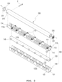
- standard device for mobile equipment for measuring structural deformation of a nuclear fuel assembly (hereinafter referred to as "standard device" according to an exemplary embodiment of the present invention will be described with reference to the accompanying FIGS. 2 to 6 .
- the standard device has a technical feature provided for scanner calibration for the mobile equipment for measuring the nuclear fuel assembly.
- the standard device includes a fixing frame 100 and a standard member 200.
- the fixing frame 100 is configured to fix the standard member 200, and is installed inside the container protecting the measurement equipment.
- the fixing frame 100 includes a protective cover 110, a lower support 120, and an upper support 130.
- the protective cover 110 protects the standard member 200 and is a portion to and from which the standard member 200 is attached and detached.
- the protective cover 110 is provided with an accommodating groove 111 to accommodate the standard member 200, wherein the accommodating groove 111 corresponds to a shape of the standard member 200.
- the accommodating groove 111 also has a quadrangular shape corresponding thereto, wherein a top portion of the accommodating groove 111 is open, whereby the standard member 200 may enter or exit the accommodating groove 111 therethrough.
- the protective cover 110 configured as described above is provided in a "U" shape consisting of a bottom surface 112 and opposite side parts 113, wherein the opposite side portions 113 of the protective cover 110 may be each provided with through holes 113a so as to reduce production cost and weight.
- both side portions of one end of the protective cover 110 may be each composed of extension portions 114 provided to extend to the outside.
- the extension parts 114 are provided with a through hole 114a penetrating both sides.
- the through hole 114a is configured to allow a rotating pin P to be passed so that the standard member 200 is axially coupled thereto.
- the standard member 200 may be axially coupled to the extension portions 114 having no bottom surface 112 and thus may not interfere with the bottom surface 112 when rotating. Accordingly, rotation of the standard member 200 may be smoothly performed.
- a fastening means 115 is installed at an opened portion of the protective cover 110.
- the fastening means 115 is configured to prevent the standard member 200 positioned in the accommodating groove 111 from being removed from the open portion.
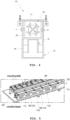
- the standard member 200 when transporting the measuring equipment, the standard member 200 is transported in a state of being laid in the accommodating groove 111 as shown in FIG. 3 . At this time, because the fastening means 115 is blocking the opened portion of the protective cover 110, the standard member 200 may be prevented in advance from being removed or moved upward.
- the rotating pin P is coupled to the protective cover 110, so that escape of the standard member 200 from the protective cover 110 does not occur.
- the plurality of the fastening means 115 may be provided in the longitudinal direction of the protective cover 110, but not limited to a specific configuration.
- one end of the fastening means 115 may be hinged to one side of the protective cover 110, and an opposite end of the fastening means 115 may be configured to fold upwardly or to fasten to an opposite side of the protective cover 110, with the one end of the fastening means 115 as the center.
- the lower support 120 is a configured to fix the protective cover 110 to the inside of the container of the measuring equipment and is located under the protective cover 110.
- the lower supporter 120 is fixed to the inside of the container and, the same as the protective cover 110, may be in the "U" shape consisting of a bottom surface 121 and opposite side parts 122.
- the through holes 122a may also be provided at the opposite side parts of the lower support 120.
- the upper support 130 serves to support the protective cover 110 to the lower support 120 and is fixed between the protective cover 110 and the lower support 120.
- the upper support 130 fixing means is not limited to a specific one and may be provided by a fixing means such as bolts and the like.
- the upper support 130 may include a top plate 131 corresponding to the bottom surface of the protective cover 110 and opposite side parts 132 bent downward from both sides of the top plate 131.
- width of the upper support 130 is provided smaller than width of the lower support 120, the opposite side parts 132 of the upper support 130 are located in the space between the opposite side parts 122 of the lower support 120.
- buffer members 140 may be further provided on both side parts 132 of the upper support 130, respectively.
- the vibration may be transferred from the container to the standard member 200 when transporting the container.
- the buffer member 140 interposed between the lower support 120 and the upper support 130 may attenuate the vibration, thereby preventing the standard member 200 from being damaged.
- the standard member 200 is a standard specification member for calibrating a scanner for measuring the nuclear fuel assembly.
- Standard member 200 is provided in a straight line and may be made of stone.
- the standard member 200 is made in a form corresponding to the accommodating groove 111 of the protective cover 110, and the length of the standard member 200 is provided to be longer than length of the protective cover 110 as shown in FIG. 3 .
- a shaft hole 210 is provided on both sides of one end of the standard member 200.
- the shaft hole 210 is provided in a shape corresponding to the through hole 114a of the protective cover 110.
- the rotating pin P is provided to provide a rotating reference of the standard member 200 by passing through the through hole 114a of the protective cover 110 and the shaft hole 210 of the standard member 200.
- the standard member 200 in order to move the standard member 200 from the protective cover 110, the standard member 200 is to be erected upright.
- the rotating pin P is configured to become a shaft when the standard member 200 is erected.
- an upper plate 220 and a lower plate 230 are installed at both end portions of the standard member 200, respectively.
- the upper plate 220 is a portion to which the transport means provided for erecting the standard member 200 is coupled in the process of erecting the standard member 200 with the rotating pin P as the center.
- the upper plate 220 provides a coupling means 221 for coupling with the transport means.
- the coupling means 221 is provided on the upper plate 220 and is good enough, provided the transport means such as a crane and the like is allowed to be hooked and coupled therewith.
- the coupling means 221 may be provided in a ring shape, as shown in FIGS. 2 to 4 , may be provided in a plurality of through holes.
- the lower plate 230 is configured to stably erect the standard member 200 and is detachably attached to one end of the standard member 200.
- the standard member 200 is configured to perform the calibration work of the scanner. To this end, the standard member 200 should be erected upright by being adjacent to one side of the column as shown in FIG. 6 . Since the lower plate 230 may be fixed to a floor adjacent to the one side of the column, the standard member 200 may be stably erected upright.
- the lower plate 230 includes an insertion protrusion 231, and an insertion means for inserting the insertion protrusion 231 may be provided on the floor adjacent to the one side of the column.
- the measuring equipment stored in the container is transported to a measurement site.
- the container may be transported by land, sea, or air.
- the container transported to the measurement site is removed of the cover thereof for measuring the nuclear fuel assembly, whereby the measuring equipment provided on a base is exposed to the outside.
- supports are rotated to and positioned at the outside of a boundary of the base, whereby the base is fixed to the ground without moving.
- the column is erected upright by operating a hydraulic cylinder.
- the calibration work of the scanner is performed.
- the standard member provided on one side of the base is fixed to the transport means.
- a crane may be provided as the transport means.
- a transport hanger 300 may be provided as a connection medium between the crane and the standard member 200.
- the crane is to lift the transport hanger 300.
- the fastening means 115 is released to open the opened portion of the protective cover 110.
- the standard member 200 is erected upright while being rotated between the extension portions 114.
- the rotating pin P is separated from the through hole 114a of the protective cover 110 and the shaft hole 210 of the standard 200.
- the standard member 200 becomes to be in a state free to move on the protective cover 110.
- the standard member 200 is fixed to the floor adjacent to the one side of the column by operating the crane.
- the insertion protrusion 231 provided on the lower plate 230 of the standard member 200 is coupled to the floor adjacent to the one side of the column, whereby the standard member 200 becomes to be in a state erected upright adjacent to the one side of the column as shown in FIG. 6 .
- the calibration work of the scanner is performed through measuring the standard member 200 by operating the scanner.
- the calibration work is performed through the standard member 200 with respect to standard values such as length, envelope, slope, and the like of the nuclear fuel assembly input to the scanner.
- the standard member 200 is laid and seated on the accommodating groove 111 of protective cover 110 by performing the above-described series of procedures in reverse order.
- the standard device for the mobile equipment for measuring structural deformation of the nuclear fuel assembly has a technical feature that allows the calibration work of the scanner to be performed in the mobile equipment for measuring structural deformation of the nuclear fuel assembly.
- the nuclear fuel assembly may be stably introduced into the nuclear reactor.
- fixing frame 110 protective cover 111: accommodating groove 112,121: bottom surface 113,122,132: side portion 113a, 122a: through hole 114: extension portion 114a: through hole 115: fastening means 120: lower support 130: upper support 131: top plate 140: buffer member 200: standard 210: shaft hole 220: upper plate 221: coupling means 230: lower plate 231: insertion protrusion 300: transport hanger
Landscapes
- Physics & Mathematics (AREA)
- Engineering & Computer Science (AREA)
- General Engineering & Computer Science (AREA)
- High Energy & Nuclear Physics (AREA)
- Plasma & Fusion (AREA)
- General Physics & Mathematics (AREA)
- Monitoring And Testing Of Nuclear Reactors (AREA)
Claims (4)
- Standardvorrichtung für mobile Ausrüstung, wobei die Standardvorrichtung ausgestattet ist mit einem Scanner zum Messen von struktureller Deformation einer Kernbrennstoffeinrichtung (10), wobei die Standardvorrichtung ferner aufweist:einen Behälter, eine Messausrüstung und einen Befestigungsrahmen (100) zum Befestigen eines Standardelements (200), wobei der Befestigungsrahmen an einer Seite der Messausrüstung befestigt ist, untergebracht in dem Behälter der Ausrüstung, und wobeidas Standardelement konfiguriert ist, um von dem Befestigungsrahmen abnehmbar zu sein, um um einen Endabschnitt des Befestigungsrahmens herum zu rotieren und um zu einer Kernbrennstoffeinrichtungsstandardspezifikation zu korrespondieren,wobei eine obere Platte (220), die mit einem Kupplungsmittel (221) versehen ist, das konfiguriert ist, um mit einem Transportmittel gekuppelt zu werden, mit einem Endabschnitt des Standardelements gekuppelt ist, und wobeieine untere Platte (230), die konfiguriert ist, um an einer Seite der Messausrüstung aufrecht errichtet und befestigt zu sein, mit einem entgegengesetzten Endabschnitt des Standardelements gekuppelt ist,wobei das Standardelement ein Standardspezifikationselement zum Kalibrieren des Scanners zum Messen der Nuklearbrennstoffeinrichtung ist, um die Genauigkeit des Messens der Nuklearbrennstoffeinrichtung zu erhöhen.
- Standardvorrichtung gemäß Anspruch 1, wobei der Befestigungsrahmen aufweist:eine Schutzabdeckung, die versehen ist mit einer Aufnahmenut, die konfiguriert ist, um das Standelement aufzunehmen, und mit einem Befestigungsmittel, das konfiguriert ist, um zu verhindern, dass das Standardelement, das in der Aufnahmenut aufgenommen ist, entnommen werden kann,einen unteren Halter, der unter der Schutzabdeckung bereitgestellt ist und an dem Behälter befestigt ist, und einen oberen Halter, der zwischen der Schutzabdeckung und dem unteren Halter installiert ist und der konfiguriert ist, um die Schutzabdeckung an dem unteren Halter zu befestigen.
- Standardvorrichtung gemäß Anspruch 2, wobei eine Mehrzahl von Pufferelementen ferner zwischen beiden Seitenabschnitten des oberen Halters und des unteren Halters in einer Längsrichtung des unteren Halters bereitgestellt sind.
- Standardvorrichtung gemäß Anspruch 2 oder 3, wobei Durchgangslöcher an beiden Seitenabschnitten eines Endabschnitts der Schutzabdeckung bereitgestellt sind,ein Schaftloch, das zu den Durchgangslöchern korrespondiert, an dem einen Endabschnitt des Standardelements bereitgestellt ist, undein Drehzapfen durch die Durchgangslöcher und das Schaftloch hindurch bereitgestellt ist, um es dem Standardelement zu ermöglichen, um den einen Endabschnitt der Schutzabdeckung zu rotieren.
Applications Claiming Priority (2)
| Application Number | Priority Date | Filing Date | Title |
|---|---|---|---|
| KR1020170094229A KR101906855B1 (ko) | 2017-07-25 | 2017-07-25 | 이동형 핵연료 집합체 구조 변형 측정장비의 스탠다드 |
| PCT/KR2017/011025 WO2019022298A1 (ko) | 2017-07-25 | 2017-09-29 | 이동형 핵연료 집합체 구조 변형 측정장비의 스탠다드 |
Publications (3)
| Publication Number | Publication Date |
|---|---|
| EP3660864A1 EP3660864A1 (de) | 2020-06-03 |
| EP3660864A4 EP3660864A4 (de) | 2021-04-07 |
| EP3660864B1 true EP3660864B1 (de) | 2024-11-06 |
Family
ID=63865047
Family Applications (1)
| Application Number | Title | Priority Date | Filing Date |
|---|---|---|---|
| EP17919393.3A Active EP3660864B1 (de) | 2017-07-25 | 2017-09-29 | Standard für mobile ausrüstung zur messung der strukturellen verformung eines kernbrennstabbündels |
Country Status (7)
| Country | Link |
|---|---|
| US (1) | US11232876B2 (de) |
| EP (1) | EP3660864B1 (de) |
| JP (1) | JP6876865B2 (de) |
| KR (1) | KR101906855B1 (de) |
| CN (1) | CN110945602B (de) |
| ES (1) | ES3002212T3 (de) |
| WO (1) | WO2019022298A1 (de) |
Families Citing this family (1)
| Publication number | Priority date | Publication date | Assignee | Title |
|---|---|---|---|---|
| RU2738751C1 (ru) * | 2020-07-01 | 2020-12-16 | Общество с ограниченной ответственностью Научно-производственная фирма "Сосны" | Способ ультразвукового контроля параметров формоизменения тепловыделяющих сборок ядерных реакторов |
Family Cites Families (19)
| Publication number | Priority date | Publication date | Assignee | Title |
|---|---|---|---|---|
| US4175000A (en) * | 1973-10-23 | 1979-11-20 | The Babcock & Wilcox Company | Method for inspecting nuclear reactor fuel elements |
| JPS60219590A (ja) * | 1984-04-14 | 1985-11-02 | 株式会社東芝 | 燃料チヤンネルボツクス測定装置 |
| JPS6165190A (ja) * | 1984-09-06 | 1986-04-03 | 株式会社東芝 | 燃料チヤンネル測定装置 |
| JPH0658426B2 (ja) | 1987-09-22 | 1994-08-03 | 三菱原子燃料株式会社 | 核燃料集合体直角度調整装置 |
| US5126098A (en) * | 1991-02-25 | 1992-06-30 | Westinghouse Electric Corp. | Method of straightening a bowed nuclear fuel assembly |
| US6017181A (en) * | 1994-05-27 | 2000-01-25 | J&R Engineering Co., Inc. | Cask transporter |
| US7388369B2 (en) * | 2004-11-30 | 2008-06-17 | Electric Power Research Institute, Inc. | Method and apparatus for measuring hydrogen concentration in zirconium alloy components in the fuel pool of a nuclear power plant |
| KR100680483B1 (ko) | 2005-12-16 | 2007-02-08 | 두산중공업 주식회사 | 핵연료 이송기의 수평수직 전환장치 |
| KR100958350B1 (ko) | 2008-07-18 | 2010-05-19 | 한전원자력연료 주식회사 | 핵연료 집합체의 검사/수리대 |
| FR2936048B1 (fr) * | 2008-09-15 | 2010-12-03 | Areva Nc | Dispositif de mesure et de correction d'un defaut de parallelisme d'un crayon de combustible nucleaire |
| KR101170080B1 (ko) | 2010-07-12 | 2012-07-31 | 한전원자력연료 주식회사 | 핵연료 집합체 운반용기용 리드프레임 및 핵연료 집합체 운반용기 |
| KR20120079867A (ko) * | 2011-01-06 | 2012-07-16 | 이보영 | 램프가 달린 우산 |
| KR101207890B1 (ko) * | 2011-02-01 | 2012-12-04 | 재단법인대구경북과학기술원 | 차량용 펄스 레이다의 다중 이동 타겟의 각도 탐지장치 및 방법 |
| KR101244865B1 (ko) * | 2011-07-08 | 2013-03-18 | 한전원자력연료 주식회사 | 핵연료집합체의 지지격자 폭 측정장치 |
| KR101362707B1 (ko) | 2012-06-18 | 2014-02-13 | 한국원자력연구원 | 핵연료 피복관의 변형량 측정장치 |
| JP6058426B2 (ja) * | 2013-02-27 | 2017-01-11 | フクダ電子株式会社 | 生体情報モニタおよびそのキャリア |
| EP2966652B1 (de) * | 2014-07-08 | 2017-04-05 | Ahlberg Cameras AB | System und Verfahren zur Messung der Kernbrennelementdeformation |
| KR101673346B1 (ko) * | 2015-03-18 | 2016-11-07 | 현대자동차 주식회사 | 전해질 막 검사 장치 |
| KR101906854B1 (ko) * | 2017-07-25 | 2018-10-11 | 한전원자력연료 주식회사 | 이동형 핵연료 집합체 구조 변형 측정장비 |
-
2017
- 2017-07-25 KR KR1020170094229A patent/KR101906855B1/ko active Active
- 2017-09-29 US US16/633,487 patent/US11232876B2/en active Active
- 2017-09-29 JP JP2020502299A patent/JP6876865B2/ja active Active
- 2017-09-29 ES ES17919393T patent/ES3002212T3/es active Active
- 2017-09-29 CN CN201780093450.1A patent/CN110945602B/zh active Active
- 2017-09-29 EP EP17919393.3A patent/EP3660864B1/de active Active
- 2017-09-29 WO PCT/KR2017/011025 patent/WO2019022298A1/ko not_active Ceased
Also Published As
| Publication number | Publication date |
|---|---|
| KR101906855B1 (ko) | 2018-10-11 |
| EP3660864A4 (de) | 2021-04-07 |
| US20200279663A1 (en) | 2020-09-03 |
| CN110945602A (zh) | 2020-03-31 |
| EP3660864A1 (de) | 2020-06-03 |
| JP2020527714A (ja) | 2020-09-10 |
| ES3002212T3 (en) | 2025-03-06 |
| WO2019022298A1 (ko) | 2019-01-31 |
| CN110945602B (zh) | 2022-06-21 |
| JP6876865B2 (ja) | 2021-05-26 |
| US11232876B2 (en) | 2022-01-25 |
Similar Documents
| Publication | Publication Date | Title |
|---|---|---|
| US11887739B2 (en) | Nuclear reactor refueling methods and apparatuses | |
| JP3121077B2 (ja) | 加圧水型原子炉における炉心計装装置 | |
| EP2946390B1 (de) | Vorrichtung und verfahren zum entfernen der obereinbauten aus einem kernreaktordruckbehälter | |
| GB2268313A (en) | Intergrated head package for top mounted nuclear insrumentation | |
| US20130003910A1 (en) | Hold-down spring unit for top nozzle of nuclear fuel assembly, and top nozzle for nuclear fuel assembly employing the hold-down spring unit | |
| KR20150106450A (ko) | 핵 구성요소의 차폐된 재배치를 위한 방법 및 장치 | |
| CN104919532B (zh) | 用于给具有器械穿透凸缘的核反应堆更换燃料的方法和装置 | |
| US11232876B2 (en) | Standard for mobile equipment for measuring structural deformation of nuclear fuel assembly | |
| US4859404A (en) | Reactor vessel internals storage area arrangement | |
| US4729869A (en) | Modular radiation shielding system | |
| EP3660863B1 (de) | Mobile ausrüstung zur messung der strukturellen verformung eines kernbrennstoffelements | |
| US20210158981A1 (en) | Decommissioning method of biodegradable concrete of pwr type nuclear power plant | |
| US4448744A (en) | Method of loading and/or unloading a nuclear reactor, and support member, especially for the foregoing method | |
| CN106575530A (zh) | 用于从压水式反应堆的堆芯中取出堆芯内仪表的方法 | |
| JP5730156B2 (ja) | 制御棒クラスタ案内管の支持ピン交換装置 | |
| EP3926644B1 (de) | Verfahren zur demontage von kernkraftwerken unter wasser | |
| Bosch et al. | Development of Instrumented Fuel Pin Testing in the BR2 Reactor for the P2M Project: Bosch, Gouat, Torres Oliver, Boer, Verwerft, Van den Bosch, Béjaoui, Vernier, and Ambard | |
| US5126098A (en) | Method of straightening a bowed nuclear fuel assembly | |
| JP6444199B2 (ja) | 下部炉心構造物の組立方法 | |
| US10128007B2 (en) | Chimneys having joinable upper and lower sections where the lower section has internal partitions | |
| US10090071B2 (en) | Systems and methods for disposing of one or more radioactive components from nuclear reactors of nuclear plants | |
| JPWO2001069609A1 (ja) | 機器の取扱方法 | |
| Gaillot et al. | Jules Horowitz reactor. development of an experimental loop integrating an optimized irradiation process. | |
| DISTRICT | HA LLAMNUCLEAR POWER FACI LITY | |
| JPH10332869A (ja) | 原子炉建屋用プールゲート構造 |
Legal Events
| Date | Code | Title | Description |
|---|---|---|---|
| STAA | Information on the status of an ep patent application or granted ep patent |
Free format text: STATUS: THE INTERNATIONAL PUBLICATION HAS BEEN MADE |
|
| PUAI | Public reference made under article 153(3) epc to a published international application that has entered the european phase |
Free format text: ORIGINAL CODE: 0009012 |
|
| STAA | Information on the status of an ep patent application or granted ep patent |
Free format text: STATUS: REQUEST FOR EXAMINATION WAS MADE |
|
| 17P | Request for examination filed |
Effective date: 20200214 |
|
| AK | Designated contracting states |
Kind code of ref document: A1 Designated state(s): AL AT BE BG CH CY CZ DE DK EE ES FI FR GB GR HR HU IE IS IT LI LT LU LV MC MK MT NL NO PL PT RO RS SE SI SK SM TR |
|
| AX | Request for extension of the european patent |
Extension state: BA ME |
|
| DAV | Request for validation of the european patent (deleted) | ||
| DAX | Request for extension of the european patent (deleted) | ||
| REG | Reference to a national code |
Ref country code: DE Ref legal event code: R079 Ref document number: 602017086025 Country of ref document: DE Free format text: PREVIOUS MAIN CLASS: G21C0017060000 Ipc: G21C0003334000 |
|
| A4 | Supplementary search report drawn up and despatched |
Effective date: 20210311 |
|
| RIC1 | Information provided on ipc code assigned before grant |
Ipc: G21F 5/012 20060101ALI20210304BHEP Ipc: G01B 11/16 20060101ALI20210304BHEP Ipc: G21F 5/06 20060101ALI20210304BHEP Ipc: G21C 17/06 20060101ALI20210304BHEP Ipc: G21C 3/334 20060101AFI20210304BHEP |
|
| GRAP | Despatch of communication of intention to grant a patent |
Free format text: ORIGINAL CODE: EPIDOSNIGR1 |
|
| STAA | Information on the status of an ep patent application or granted ep patent |
Free format text: STATUS: GRANT OF PATENT IS INTENDED |
|
| INTG | Intention to grant announced |
Effective date: 20240515 |
|
| GRAS | Grant fee paid |
Free format text: ORIGINAL CODE: EPIDOSNIGR3 |
|
| GRAA | (expected) grant |
Free format text: ORIGINAL CODE: 0009210 |
|
| STAA | Information on the status of an ep patent application or granted ep patent |
Free format text: STATUS: THE PATENT HAS BEEN GRANTED |
|
| AK | Designated contracting states |
Kind code of ref document: B1 Designated state(s): AL AT BE BG CH CY CZ DE DK EE ES FI FR GB GR HR HU IE IS IT LI LT LU LV MC MK MT NL NO PL PT RO RS SE SI SK SM TR |
|
| REG | Reference to a national code |
Ref country code: GB Ref legal event code: FG4D |
|
| REG | Reference to a national code |
Ref country code: CH Ref legal event code: EP |
|
| REG | Reference to a national code |
Ref country code: DE Ref legal event code: R096 Ref document number: 602017086025 Country of ref document: DE |
|
| REG | Reference to a national code |
Ref country code: IE Ref legal event code: FG4D |
|
| REG | Reference to a national code |
Ref country code: ES Ref legal event code: FG2A Ref document number: 3002212 Country of ref document: ES Kind code of ref document: T3 Effective date: 20250306 |
|
| REG | Reference to a national code |
Ref country code: LT Ref legal event code: MG9D |
|
| REG | Reference to a national code |
Ref country code: NL Ref legal event code: MP Effective date: 20241106 |
|
| PG25 | Lapsed in a contracting state [announced via postgrant information from national office to epo] |
Ref country code: HR Free format text: LAPSE BECAUSE OF FAILURE TO SUBMIT A TRANSLATION OF THE DESCRIPTION OR TO PAY THE FEE WITHIN THE PRESCRIBED TIME-LIMIT Effective date: 20241106 Ref country code: PT Free format text: LAPSE BECAUSE OF FAILURE TO SUBMIT A TRANSLATION OF THE DESCRIPTION OR TO PAY THE FEE WITHIN THE PRESCRIBED TIME-LIMIT Effective date: 20250306 Ref country code: IS Free format text: LAPSE BECAUSE OF FAILURE TO SUBMIT A TRANSLATION OF THE DESCRIPTION OR TO PAY THE FEE WITHIN THE PRESCRIBED TIME-LIMIT Effective date: 20250306 |
|
| PG25 | Lapsed in a contracting state [announced via postgrant information from national office to epo] |
Ref country code: FI Free format text: LAPSE BECAUSE OF FAILURE TO SUBMIT A TRANSLATION OF THE DESCRIPTION OR TO PAY THE FEE WITHIN THE PRESCRIBED TIME-LIMIT Effective date: 20241106 Ref country code: NL Free format text: LAPSE BECAUSE OF FAILURE TO SUBMIT A TRANSLATION OF THE DESCRIPTION OR TO PAY THE FEE WITHIN THE PRESCRIBED TIME-LIMIT Effective date: 20241106 |
|
| REG | Reference to a national code |
Ref country code: AT Ref legal event code: MK05 Ref document number: 1740329 Country of ref document: AT Kind code of ref document: T Effective date: 20241106 |
|
| PG25 | Lapsed in a contracting state [announced via postgrant information from national office to epo] |
Ref country code: BG Free format text: LAPSE BECAUSE OF FAILURE TO SUBMIT A TRANSLATION OF THE DESCRIPTION OR TO PAY THE FEE WITHIN THE PRESCRIBED TIME-LIMIT Effective date: 20241106 |
|
| PG25 | Lapsed in a contracting state [announced via postgrant information from national office to epo] |
Ref country code: NO Free format text: LAPSE BECAUSE OF FAILURE TO SUBMIT A TRANSLATION OF THE DESCRIPTION OR TO PAY THE FEE WITHIN THE PRESCRIBED TIME-LIMIT Effective date: 20250206 |
|
| PG25 | Lapsed in a contracting state [announced via postgrant information from national office to epo] |
Ref country code: GR Free format text: LAPSE BECAUSE OF FAILURE TO SUBMIT A TRANSLATION OF THE DESCRIPTION OR TO PAY THE FEE WITHIN THE PRESCRIBED TIME-LIMIT Effective date: 20250207 Ref country code: LV Free format text: LAPSE BECAUSE OF FAILURE TO SUBMIT A TRANSLATION OF THE DESCRIPTION OR TO PAY THE FEE WITHIN THE PRESCRIBED TIME-LIMIT Effective date: 20241106 Ref country code: AT Free format text: LAPSE BECAUSE OF FAILURE TO SUBMIT A TRANSLATION OF THE DESCRIPTION OR TO PAY THE FEE WITHIN THE PRESCRIBED TIME-LIMIT Effective date: 20241106 |
|
| PG25 | Lapsed in a contracting state [announced via postgrant information from national office to epo] |
Ref country code: PL Free format text: LAPSE BECAUSE OF FAILURE TO SUBMIT A TRANSLATION OF THE DESCRIPTION OR TO PAY THE FEE WITHIN THE PRESCRIBED TIME-LIMIT Effective date: 20241106 |
|
| PG25 | Lapsed in a contracting state [announced via postgrant information from national office to epo] |
Ref country code: RS Free format text: LAPSE BECAUSE OF FAILURE TO SUBMIT A TRANSLATION OF THE DESCRIPTION OR TO PAY THE FEE WITHIN THE PRESCRIBED TIME-LIMIT Effective date: 20250206 |
|
| PG25 | Lapsed in a contracting state [announced via postgrant information from national office to epo] |
Ref country code: SM Free format text: LAPSE BECAUSE OF FAILURE TO SUBMIT A TRANSLATION OF THE DESCRIPTION OR TO PAY THE FEE WITHIN THE PRESCRIBED TIME-LIMIT Effective date: 20241106 |
|
| PG25 | Lapsed in a contracting state [announced via postgrant information from national office to epo] |
Ref country code: DK Free format text: LAPSE BECAUSE OF FAILURE TO SUBMIT A TRANSLATION OF THE DESCRIPTION OR TO PAY THE FEE WITHIN THE PRESCRIBED TIME-LIMIT Effective date: 20241106 |
|
| PG25 | Lapsed in a contracting state [announced via postgrant information from national office to epo] |
Ref country code: EE Free format text: LAPSE BECAUSE OF FAILURE TO SUBMIT A TRANSLATION OF THE DESCRIPTION OR TO PAY THE FEE WITHIN THE PRESCRIBED TIME-LIMIT Effective date: 20241106 |
|
| PG25 | Lapsed in a contracting state [announced via postgrant information from national office to epo] |
Ref country code: RO Free format text: LAPSE BECAUSE OF FAILURE TO SUBMIT A TRANSLATION OF THE DESCRIPTION OR TO PAY THE FEE WITHIN THE PRESCRIBED TIME-LIMIT Effective date: 20241106 |
|
| PG25 | Lapsed in a contracting state [announced via postgrant information from national office to epo] |
Ref country code: SK Free format text: LAPSE BECAUSE OF FAILURE TO SUBMIT A TRANSLATION OF THE DESCRIPTION OR TO PAY THE FEE WITHIN THE PRESCRIBED TIME-LIMIT Effective date: 20241106 |
|
| PG25 | Lapsed in a contracting state [announced via postgrant information from national office to epo] |
Ref country code: IT Free format text: LAPSE BECAUSE OF FAILURE TO SUBMIT A TRANSLATION OF THE DESCRIPTION OR TO PAY THE FEE WITHIN THE PRESCRIBED TIME-LIMIT Effective date: 20241106 |
|
| REG | Reference to a national code |
Ref country code: DE Ref legal event code: R097 Ref document number: 602017086025 Country of ref document: DE |
|
| PG25 | Lapsed in a contracting state [announced via postgrant information from national office to epo] |
Ref country code: SE Free format text: LAPSE BECAUSE OF FAILURE TO SUBMIT A TRANSLATION OF THE DESCRIPTION OR TO PAY THE FEE WITHIN THE PRESCRIBED TIME-LIMIT Effective date: 20241106 |
|
| PLBE | No opposition filed within time limit |
Free format text: ORIGINAL CODE: 0009261 |
|
| STAA | Information on the status of an ep patent application or granted ep patent |
Free format text: STATUS: NO OPPOSITION FILED WITHIN TIME LIMIT |
|
| PGFP | Annual fee paid to national office [announced via postgrant information from national office to epo] |
Ref country code: DE Payment date: 20250923 Year of fee payment: 9 |
|
| 26N | No opposition filed |
Effective date: 20250807 |
|
| PGFP | Annual fee paid to national office [announced via postgrant information from national office to epo] |
Ref country code: GB Payment date: 20250925 Year of fee payment: 9 |
|
| PGFP | Annual fee paid to national office [announced via postgrant information from national office to epo] |
Ref country code: FR Payment date: 20250922 Year of fee payment: 9 |
|
| PGFP | Annual fee paid to national office [announced via postgrant information from national office to epo] |
Ref country code: CZ Payment date: 20250923 Year of fee payment: 9 |
|
| PGFP | Annual fee paid to national office [announced via postgrant information from national office to epo] |
Ref country code: ES Payment date: 20251029 Year of fee payment: 9 |
|
| REG | Reference to a national code |
Ref country code: CH Ref legal event code: H13 Free format text: ST27 STATUS EVENT CODE: U-0-0-H10-H13 (AS PROVIDED BY THE NATIONAL OFFICE) Effective date: 20260425 |