EP3660879A1 - Sicherheitsvorrichtung für ein hochspannungsrelais - Google Patents
Sicherheitsvorrichtung für ein hochspannungsrelais Download PDFInfo
- Publication number
- EP3660879A1 EP3660879A1 EP18208801.3A EP18208801A EP3660879A1 EP 3660879 A1 EP3660879 A1 EP 3660879A1 EP 18208801 A EP18208801 A EP 18208801A EP 3660879 A1 EP3660879 A1 EP 3660879A1
- Authority
- EP
- European Patent Office
- Prior art keywords
- voltage relay
- safety device
- position sensor
- driving means
- rack
- Prior art date
- Legal status (The legal status is an assumption and is not a legal conclusion. Google has not performed a legal analysis and makes no representation as to the accuracy of the status listed.)
- Withdrawn
Links
- 239000011810 insulating material Substances 0.000 claims description 9
- 125000006850 spacer group Chemical group 0.000 claims description 6
- 238000000034 method Methods 0.000 claims description 5
- 238000012423 maintenance Methods 0.000 description 4
- 229930040373 Paraformaldehyde Natural products 0.000 description 2
- 239000000853 adhesive Substances 0.000 description 2
- 230000001070 adhesive effect Effects 0.000 description 2
- 230000000295 complement effect Effects 0.000 description 2
- 230000008878 coupling Effects 0.000 description 2
- 238000010168 coupling process Methods 0.000 description 2
- 238000005859 coupling reaction Methods 0.000 description 2
- 230000002950 deficient Effects 0.000 description 2
- 230000004048 modification Effects 0.000 description 2
- 238000012986 modification Methods 0.000 description 2
- 229920006324 polyoxymethylene Polymers 0.000 description 2
- 238000005476 soldering Methods 0.000 description 2
- 229920002292 Nylon 6 Polymers 0.000 description 1
- 208000027418 Wounds and injury Diseases 0.000 description 1
- 230000004323 axial length Effects 0.000 description 1
- 230000006378 damage Effects 0.000 description 1
- 230000001419 dependent effect Effects 0.000 description 1
- 208000014674 injury Diseases 0.000 description 1
- 239000000463 material Substances 0.000 description 1
- 230000002093 peripheral effect Effects 0.000 description 1
- -1 polyoxymethylene Polymers 0.000 description 1
- 239000004800 polyvinyl chloride Substances 0.000 description 1
- 238000000926 separation method Methods 0.000 description 1
- 239000012815 thermoplastic material Substances 0.000 description 1
Images

Classifications
-
- H—ELECTRICITY
- H01—ELECTRIC ELEMENTS
- H01H—ELECTRIC SWITCHES; RELAYS; SELECTORS; EMERGENCY PROTECTIVE DEVICES
- H01H50/00—Details of electromagnetic relays
- H01H50/08—Indicators; Distinguishing marks
-
- H—ELECTRICITY
- H01—ELECTRIC ELEMENTS
- H01H—ELECTRIC SWITCHES; RELAYS; SELECTORS; EMERGENCY PROTECTIVE DEVICES
- H01H50/00—Details of electromagnetic relays
- H01H50/54—Contact arrangements
- H01H50/541—Auxiliary contact devices
- H01H50/545—Self-contained, easily replaceable microswitches
-
- H—ELECTRICITY
- H01—ELECTRIC ELEMENTS
- H01H—ELECTRIC SWITCHES; RELAYS; SELECTORS; EMERGENCY PROTECTIVE DEVICES
- H01H9/00—Details of switching devices, not covered by groups H01H1/00 - H01H7/00
- H01H9/16—Indicators for switching condition, e.g. "on" or "off"
- H01H9/167—Circuits for remote indication
Definitions
- the invention relates to a safety device for a high-voltage relay.
- High-voltage relays are widely used in high-voltage systems for automatically closing and interrupting an electric connection in a high-voltage circuit.
- high-voltage addresses a voltage of at least 1 kV DC (Directed Current) or a voltage of at least 1,5 kV AC (Alternating Current) between connecting contacts of the high-voltage relay when the electric connection between the connecting contacts is interrupted by the high-voltage relay.
- DC Directed Current
- AC Alternating Current
- a high-voltage relay usually has an elongate contact arm establishing an electric connection between connecting contacts of the high-voltage relay in a normal position and interrupting the electric connection between the connecting contacts in a deflected position, i.e. the contact arm is preloaded to the normal position and has to be displaced by applying a force to the contact arm for the deflected position.
- the contact arm may be configured to be a contact spring which may be elastically bended to the deflected position.
- the contact arm may be formed as a rigid element which may be displaced, particularly pivoted, to the deflected position and is preloaded to the normal position by a separate spring.
- the state of the high-voltage relay is called a closed state if the contact arm is in the normal position, and the state of the high-voltage relay is called an open state if the contact arm is in the deflected position.
- the normal position of the contact arm may instead correspond to the open state of the high-voltage relay, and the deflected position of the contact arm may instead correspond to the closed state of the high-voltage relay.
- the force is applied to the contact arm by an actuator being mechanically coupled to the contact arm.
- the actuator has a coupling portion for engaging the contact arm and a magnetizable portion which is arranged and guided displaceable within in a coil.
- the coil When an electric current is applied to the coil the coil generates a magnetic field magnetizing the magnetizable portion of the actuator.
- the magnetized portion of the actuator interacts with the magnetic field of the coil and experiences a magnetic force displacing the actuator which in turn bends or displaces the contact arm from the normal position to the deflected position thus interrupting the electric connection between the connecting contacts of the high-voltage relay.
- the high-voltage relay may further have a body for supporting and relatively arranging the coil, the actuator, the contact arm and the connecting contacts wherein the contact arm is arranged at an outer side of the body in many cases while the actuator extends from inside the body via a through-hole of the body to the outer contact arm.
- a high-voltage relay being mounted to a high-voltage system is often hidden by other components of the high-voltage system. In these cases, the state of the high-voltage relay of the high-voltage system cannot be recognized visually.
- the high-voltage systems is usually subjected to a regular maintenance. If the maintenance of the high-voltage system was performed when the high-voltage relay is in the closed state, there would be a high risk of death or at least injury for the maintenance personnel.
- the high-voltage relay should have a so called safety contact for connecting thereto a safety circuit which may, for example, block an access to the high-voltage system or, in case of an access, activate a safety interrupt if the high-voltage relay is defectively and unnoticeably in the closed state.
- the object to be solved by the invention is to provide a high-voltage relay with a safety contact.
- a safety device for a high-voltage relay In other words, a separate safety device is provided for complementing the high-voltage relay.
- the high-voltage relay for example, may be mounted to a high-voltage system. Note, that the high-voltage relay itself needs no modification due to the safety device. This is crucial for not losing the warranty of a manufacturer of the high-voltage relay.
- the safety device may have a rack.
- the rack provides a support for any further component of the safety device and allows for an attachment of the safety device.
- the safety device may further have a position sensor being fixed to the rack and having a probing element.
- the position sensor has connecting contacts and, thus, can provide the high-voltage relay with an external safety contact.
- the safety device has a driving means being joined to the probing element and being configured for mechanically engaging a contact arm of the high-voltage relay.
- the driving means thus, forms a mechanical coupling between the probing element of the position sensor and the contact arm of the high-voltage relay.
- Different high voltage relays may have contact arms which are formed and arranged differently.
- a skilled person may readily adapt the driving means to a contact arm of a particular high voltage relay by providing the driving means with a configuration, i.e. mechanical structure, properly matching the contact arm of the particular high voltage relay.
- the driving means provides a mechanical priority control, i.e. a mechanically forced guidance.
- the position sensor is provided as a switch pin and/or the position sensor has an elastic element preloading the probing element to a default state.
- Switch pins are commercially available in a large variety. Particularly, they may have very small dimensions, i.e. may be formed very thin, requiring little space in the mounted state.
- the elastic element may be a spiral spring or the like.
- the preloaded default state of the position sensor should correspond to the closed state of the high-voltage relay for safety reasons. In case the safety device itself is defective, at least the position sensor simulates the closed state of the high-voltage relay. In this way, safety may be achieved despite a defective safety device.
- the driving means preferably has a body section and two protrusions extending from the body section and being arranged at a distance.
- the protrusions may laterally engage the contact arm of the high-voltage relay by embracing the contact arm. Due to the distance between the protrusions the contact arm and the driving means may move relative to each other in the engaged state of the driving means.
- the driving means may have additional protrusions improving an insulating function of the driving means.
- a stroke of the position sensor is smaller than the distance of the two protrusions. This configuration allows position sensors to be used which have a smaller stroke than a stroke of the contact arm, i.e. the driving element may transform a stroke difference between the position sensor and the contact arm.
- the driving means has an insulating material or consists thereof and/or the driving means has a cylindric body section and/or the driving means has disc-shaped protrusions.
- the insulating material allows for a safe galvanic separation of the position sensor form the contact arm.
- Exemplary insulating materials are thermoplastic materials as polyoxymethylene (POM), polyethter-etherketone (PEEK), polyvinylchloride (PVC) or polyamide 6 (PA6).
- POM polyoxymethylene
- PEEK polyethter-etherketone
- PVC polyvinylchloride
- PA6 polyamide 6
- the body section of the driving means must be sufficiently large in order to ensure a certain minimal distance between the probing element of the position sensor and the contact arm of the high-voltage relay.
- the cylindric body section may have a plurality of axial sections having different diameters.
- the diameter of any cylindric body section may be in a range from 0.5 mm to 2.5 mm and more preferably in a range from 1.0 mm and 2.0 mm.
- the disc-shaped protrusions may have different diameters.
- the diameter of any disc-shaped protrusion may be in a range from 2.0 mm and 4.5 mm.
- An overall axial length of the driving means may be in a range from 7 mm to 13 mm and more preferably in a range from 9 mm to 11 mm.
- the cylindric shape of the body section and the disc-like shape of the peripheral protrusions result in a rotational symmetry of the driving means. Due to the rotational symmetry of the driving means any accidental rotation of the driving means does not affect the engagement with the contact arm.
- the driving means may have a recess for accommodating a free end of the probing element of the position sensor wherein particularly the free end of the probing element of the position sensor is accommodated in the recess and secured to the driving means.
- the recess in the body section of the driving member allows for an easy joint of the driving member to the probing element.
- the free end of the probing member may be tight fitted within the recess or inserted into and bonded to the recess by means of an adhesive.
- the rack preferably has an insulating material or consists thereof and/or the rack includes at least an abutment shoulder for aligning the safety device relative to the high-voltage relay. Due to the insulating material both the rack and any component of the safety device being fixed to the rack are electrically isolated from the high-voltage relay. The abutment shoulder allows for a defined exact relative position of the safety device in the mounted state.
- the rack is configured for securing the safety device to a high-voltage relay and/or the rack has two plates being arranged parallel and/or opposite to each other and at least one spacer being arranged between the plates and/or extending perpendicular to the plates and/or being connected to either plate.
- the rack may be shaped complementary to the high-voltage relay in order to provide a positive fit. If the rack has two opposite plates which are connected by one or more spacers, only the plates have to be shaped to fit the shape of the high-voltage relay.
- the rack may further include at least one protrusion engaging an undercut of the high-voltage relay. This is a clever way to provide a secure mechanical connection between the rack and the high-voltage relay on the one hand and to not at all modify the high-voltage relay on the other hand.
- the safety device has two or more position sensors and a corresponding number of driving means each being joined to one position sensor. These embodiments may be used for complex high-voltage relays having two or more contact arms.
- the safety device preferably has a printed circuit board being attached to the rack and electrically connected to each position sensor and/or having a pluggable connecting section.
- the printed circuit board (PCB) may be screwed to the rack, particularly opposite to the high-voltage relay. Connecting contacts of the position sensor may be electrically connected to the printed circuit board, particularly by means of soldering.
- the pluggable connection section of the printed circuit board allows a plug to be plugged to the safety device, i.e. a plug of an external safety circuit.
- Another subject of the invention is an arrangement comprising a high-voltage relay and a safety device according to the invention being secured to the high-voltage relay.
- This arrangement satisfies the safety provision concerning high-voltage relays and functionally corresponds to a high-voltage relay provided originally with a safety contact.
- an operating direction of the position sensor is at least substantially perpendicular to a main extension of the contact arm of the high-voltage relay. This arrangement is preferable when the contact arm is bended or displaced from a normal position to a deflected position in a direction perpendicular to its main extension.
- Yet another subject of the invention is a use of an arrangement according to the invention for satisfying a safety provision concerning a high-voltage relay.
- the inventive arrangement of a high-voltage relay and a safety device secured to the high-voltage relay may be used in conformity with the safety provision.
- a method for operating a high-voltage relay is suggested. The method is performed for operating a high-voltage relay without any original safety contact safely and in conformity with the safety provision.
- the method may have the step of driving a position sensor by a contact arm of a high voltage relay, the contact arm being mechanically engaged by a driving means joined to the position sensor.
- a priority control i.e. a mechanically forced guidance, is established between the contact arm and the position sensor.
- the method may have the further step of detecting a state of a high-voltage relay by way of a state of the position sensor. Due to the priority control, the state of the high-voltage relay is uniquely mapped to a state of the position sensor which may be evaluated instead.
- the high-voltage relay 60 is operated by alternatively applying or not applying an electric current to the coil 64. When no electric current is applied to the coil 64, consequently, no magnetic field is generated by the coil 64. In the absence of the magnetic force the actuator 63 is in a normal position allowing the contact arm 62 for closing the electric connection between the connecting contacts 65.
- the coil 64 When, on the other hand, an electric current is applied to the coil 64 the coil 64 generates a magnetic field applying a magnetic force to the actuator 63.
- the actuator 63 is displaced by the magnetic force from the normal position to an activated position. In the activated position the actuator 63 bends the contact arm 62 thus interrupting the electric connection between the connecting contacts 65.
- the inventive arrangement may have a different high-voltage relay as well.
- the normal and operating states of the actuator 63 and, respectively, the closing and interrupting positions of the contact arm 62 may be defined differently.
- the high-voltage relay may have more than two connecting contacts 65 thus forming a changeover relay or the like.
- the high-voltage relay may have two or more contact arms 62 for controlling two or more electric connections between connecting contacts 65.
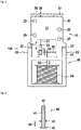
- the arrangement 100 further has a safety device 10 according to the invention.
- the safety device 10 is secured to the high-voltage relay 60.
- the arrangement 100 is used for satisfying a safety provision concerning the high-voltage relay 60 in case the safety provision is not originally satisfied by the high-voltage relay 60.
- the safety device 10 is shown in another lateral view.
- the safety device 10 has a rack 20 being configured for securing the safety device 10 to the high-voltage relay 60.
- the rack 20 consists of an insulating material and has two plates 21 being arranged parallel and opposite to each other and four spacers 24 which are arranged between the plates 21.
- the spacers 24 extend perpendicular to the plates 21 and are connected to either plate 21 by means of screws 25 (see figure 1 ).
- the rack 20 includes four protrusions 23 engaging a corresponding undercut (not shown) of the high-voltage relay 60 and four abutment shoulders 22 (see also figure 1 ) for aligning the safety device 10 relative to the high-voltage relay 60.
- the abutment shoulders 22 are formed and arranged on the plates 21 for abutting corresponding abutment surfaces of the body 61 of the high-voltage relay 60.
- the structure of the rack 20 individually depends on the shape of the body of the high-voltage relay 60 and is exemplary only.
- the rack may and should be freely adapted to the different structure of the high-voltage relay for being securable and alignable to the high-voltage relay.
- the safety device 10 also has a position sensor 30 being fixed to the rack 30 and provided as a switch pin.
- the position sensor 30 has a probing element 31 being displaceable between a default position and an activated position.
- the position sensor may have two connecting contacts wherein the electric connection between the connecting contacts is interrupted in the normal state and closed in the operating state or vice versa.
- the position sensor 30 further has an elastic element preloading the probing element 31 to the default position.
- an operating direction 33 of the position sensor 30 is perpendicular to a main extension of the contact arm 62 of the high-voltage relay 60.
- the safety device 10 has a printed circuit board (PCB) 50 being attached to the rack 20 opposite to the high-voltage relay 60 and electrically connected to the position sensor 30 by means of soldering.
- the printed circuit board has a pluggable connecting section 51 for connecting a safety circuit or the like via a complementary plug.
- the safety device 10 has a driving means 40 being joined to the probing element 31 and being configured for mechanically engaging the contact arm 62 of the high-voltage relay 60.
- the driving means 40 is shown in an enlarged cross-sectional view.
- the driving means 40 consists of an insulating material and has preferably a longitudinal body section 41 and two protrusions 43 extending from the body section 41 and being arranged at a distance 44.
- the distance 44 may be chosen such that a stroke of the position sensor 30 is smaller than the distance 44 of the two protrusions 43.
- the body section 41 has a cylindric shape, and the protrusions 43 are disc-shaped.
- the driving means 44 laterally engages the contact arm 62 by means of the protrusions 43 wherein a mechanical priority control, i.e. a mechanically forced guidance, is provided for the probing element 31 of the position sensor 30.
- the driving means 40 further has a recess 42 for accommodating a free end 32 of the probing element 31 of the position sensor 30.
- the recess 41 is formed in the body section 41.
- the free end 32 of the probing element 31 of the position sensor 30 is accommodated in the recess 42 and secured to the driving means 40 by means of an adhesive.
- Alternative ways of securing the probing element 31 to the driving means 40 i.e. tight fitting or screwing the free end 32 thereto, may be freely chosen by the skilled person.
- the safety device may have two or more position sensors 30 and a corresponding number of driving means 40 each being joined to one position sensor 30 in case the high-voltage relay has two or more contact arms.
- the position sensor 30 is driven by the contact arm 62 of the high voltage relay 60.
- the contact arm 62 interrupts the electric connection between the connecting contacts 65
- the moving member 31 of the position sensor 30 is in the default position.
- the contact arm 62 closes the electric connection between the connecting contacts 65
- the moving member 31 of the position sensor 30 is in the activated position.
- a state of the high-voltage relay 60 is detectable by evaluating the state of the position sensor 30, i.e. the position of the moving member 31.
- the state of the position sensor 30 may be evaluated by a safety circuit connected to the connecting section 51 of the printed circuit board 50.
- a substantial advantage of the inventive safety device is that the high-voltage relay may be subsequently upgraded for satisfying a safety regulation by simply forming the inventive arrangement and without any modification to the high-voltage relay itself.
- the subsequent upgrade is done very easily and at low costs.
- the high-voltage relay upgraded this way is safely operable in conformity with the safety regulation.
Landscapes
- Physics & Mathematics (AREA)
- Electromagnetism (AREA)
- Switch Cases, Indication, And Locking (AREA)
Priority Applications (1)
| Application Number | Priority Date | Filing Date | Title |
|---|---|---|---|
| EP18208801.3A EP3660879A1 (de) | 2018-11-28 | 2018-11-28 | Sicherheitsvorrichtung für ein hochspannungsrelais |
Applications Claiming Priority (1)
| Application Number | Priority Date | Filing Date | Title |
|---|---|---|---|
| EP18208801.3A EP3660879A1 (de) | 2018-11-28 | 2018-11-28 | Sicherheitsvorrichtung für ein hochspannungsrelais |
Publications (1)
| Publication Number | Publication Date |
|---|---|
| EP3660879A1 true EP3660879A1 (de) | 2020-06-03 |
Family
ID=64556729
Family Applications (1)
| Application Number | Title | Priority Date | Filing Date |
|---|---|---|---|
| EP18208801.3A Withdrawn EP3660879A1 (de) | 2018-11-28 | 2018-11-28 | Sicherheitsvorrichtung für ein hochspannungsrelais |
Country Status (1)
| Country | Link |
|---|---|
| EP (1) | EP3660879A1 (de) |
Citations (2)
| Publication number | Priority date | Publication date | Assignee | Title |
|---|---|---|---|---|
| DE102007002176A1 (de) * | 2007-01-15 | 2008-07-17 | Siemens Ag | Erfassungseinrichtung zum Erfassen des Schaltzustands eines elektromagnetischen Schaltgeräts |
| DE102013114073B3 (de) * | 2013-12-16 | 2015-06-18 | Eaton Electrical Ip Gmbh & Co. Kg | Hilfsschalter für ein Schaltgerät |
-
2018
- 2018-11-28 EP EP18208801.3A patent/EP3660879A1/de not_active Withdrawn
Patent Citations (2)
| Publication number | Priority date | Publication date | Assignee | Title |
|---|---|---|---|---|
| DE102007002176A1 (de) * | 2007-01-15 | 2008-07-17 | Siemens Ag | Erfassungseinrichtung zum Erfassen des Schaltzustands eines elektromagnetischen Schaltgeräts |
| DE102013114073B3 (de) * | 2013-12-16 | 2015-06-18 | Eaton Electrical Ip Gmbh & Co. Kg | Hilfsschalter für ein Schaltgerät |
Similar Documents
| Publication | Publication Date | Title |
|---|---|---|
| US10236681B2 (en) | Power cable assembly having a circuit protection device | |
| US8289026B2 (en) | Recording device for recording the switch state of an electromagnetic switch device | |
| US20070133150A1 (en) | Signal Input/Output Device | |
| CA2764161A1 (en) | Assembly for mounting of tube pinch type solenoid valve | |
| EP3682460B1 (de) | Relais-steuergerät mit grossem betriebsbereich | |
| US9349527B2 (en) | Current transformer having an automatic short-circuit device | |
| AU2020260673B2 (en) | Motor-driven medical suction pump and method for connecting such a suction pump to a power source | |
| CN109488805B (zh) | 阀门控制头 | |
| KR20160038018A (ko) | 구성가능한 스위치 에뮬레이터 모듈 | |
| CN111096092B (zh) | 模块化现场设备 | |
| EP1876616A2 (de) | Rücksetzungsvorrichtung für einen Begrenzungsschalter und Begrenzungsschalter mit einer solchen Vorrichtung | |
| EP1858043B1 (de) | Positionsschalter mit beweglichen Kontakten mit positivem Betrieb | |
| US10541101B1 (en) | Electric leakage protector | |
| RU2673372C1 (ru) | Серводвигатель для промышленного клапана или створки с соединительной платой и соединителем | |
| EP2911175B1 (de) | Elektromagnetisches Relais | |
| EP2637186B1 (de) | Stufenwähler und Verfahren zur Montage eines Stufenwählers | |
| US20250385445A1 (en) | Electrical connector | |
| US20170282378A1 (en) | Robot system | |
| CN112805799A (zh) | 电气元件的连接方法 | |
| US11366164B2 (en) | Switch circuit, switch device, and system | |
| JP5857239B2 (ja) | 高電圧用開閉装置 | |
| US20160181043A1 (en) | Electrical switching device equipped with means for signaling the presence of auxiliary blocks | |
| EP2482295A1 (de) | Relais mit mehreren Kontakten | |
| EP3465709B1 (de) | Stossfester elektrischer schalter | |
| KR101259859B1 (ko) | 지능형 릴레이 제어 장치 |
Legal Events
| Date | Code | Title | Description |
|---|---|---|---|
| PUAI | Public reference made under article 153(3) epc to a published international application that has entered the european phase |
Free format text: ORIGINAL CODE: 0009012 |
|
| STAA | Information on the status of an ep patent application or granted ep patent |
Free format text: STATUS: THE APPLICATION HAS BEEN PUBLISHED |
|
| AK | Designated contracting states |
Kind code of ref document: A1 Designated state(s): AL AT BE BG CH CY CZ DE DK EE ES FI FR GB GR HR HU IE IS IT LI LT LU LV MC MK MT NL NO PL PT RO RS SE SI SK SM TR |
|
| AX | Request for extension of the european patent |
Extension state: BA ME |
|
| STAA | Information on the status of an ep patent application or granted ep patent |
Free format text: STATUS: THE APPLICATION IS DEEMED TO BE WITHDRAWN |
|
| 18D | Application deemed to be withdrawn |
Effective date: 20201204 |