EP3660947B1 - Module de batterie - Google Patents
Module de batterie Download PDFInfo
- Publication number
- EP3660947B1 EP3660947B1 EP18839174.2A EP18839174A EP3660947B1 EP 3660947 B1 EP3660947 B1 EP 3660947B1 EP 18839174 A EP18839174 A EP 18839174A EP 3660947 B1 EP3660947 B1 EP 3660947B1
- Authority
- EP
- European Patent Office
- Prior art keywords
- batteries
- outer peripheral
- battery
- electrode
- lead plate
- Prior art date
- Legal status (The legal status is an assumption and is not a legal conclusion. Google has not performed a legal analysis and makes no representation as to the accuracy of the status listed.)
- Active
Links
Images




Classifications
-
- H—ELECTRICITY
- H01—ELECTRIC ELEMENTS
- H01M—PROCESSES OR MEANS, e.g. BATTERIES, FOR THE DIRECT CONVERSION OF CHEMICAL ENERGY INTO ELECTRICAL ENERGY
- H01M50/00—Constructional details or processes of manufacture of the non-active parts of electrochemical cells other than fuel cells, e.g. hybrid cells
- H01M50/50—Current conducting connections for cells or batteries
- H01M50/572—Means for preventing undesired use or discharge
- H01M50/574—Devices or arrangements for the interruption of current
- H01M50/578—Devices or arrangements for the interruption of current in response to pressure
-
- H—ELECTRICITY
- H01—ELECTRIC ELEMENTS
- H01M—PROCESSES OR MEANS, e.g. BATTERIES, FOR THE DIRECT CONVERSION OF CHEMICAL ENERGY INTO ELECTRICAL ENERGY
- H01M50/00—Constructional details or processes of manufacture of the non-active parts of electrochemical cells other than fuel cells, e.g. hybrid cells
- H01M50/20—Mountings; Secondary casings or frames; Racks, modules or packs; Suspension devices; Shock absorbers; Transport or carrying devices; Holders
- H01M50/204—Racks, modules or packs for multiple batteries or multiple cells
- H01M50/207—Racks, modules or packs for multiple batteries or multiple cells characterised by their shape
- H01M50/213—Racks, modules or packs for multiple batteries or multiple cells characterised by their shape adapted for cells having curved cross-section, e.g. round or elliptic
-
- H—ELECTRICITY
- H01—ELECTRIC ELEMENTS
- H01M—PROCESSES OR MEANS, e.g. BATTERIES, FOR THE DIRECT CONVERSION OF CHEMICAL ENERGY INTO ELECTRICAL ENERGY
- H01M50/00—Constructional details or processes of manufacture of the non-active parts of electrochemical cells other than fuel cells, e.g. hybrid cells
- H01M50/30—Arrangements for facilitating escape of gases
-
- H—ELECTRICITY
- H01—ELECTRIC ELEMENTS
- H01M—PROCESSES OR MEANS, e.g. BATTERIES, FOR THE DIRECT CONVERSION OF CHEMICAL ENERGY INTO ELECTRICAL ENERGY
- H01M50/00—Constructional details or processes of manufacture of the non-active parts of electrochemical cells other than fuel cells, e.g. hybrid cells
- H01M50/50—Current conducting connections for cells or batteries
-
- H—ELECTRICITY
- H01—ELECTRIC ELEMENTS
- H01M—PROCESSES OR MEANS, e.g. BATTERIES, FOR THE DIRECT CONVERSION OF CHEMICAL ENERGY INTO ELECTRICAL ENERGY
- H01M50/00—Constructional details or processes of manufacture of the non-active parts of electrochemical cells other than fuel cells, e.g. hybrid cells
- H01M50/50—Current conducting connections for cells or batteries
- H01M50/502—Interconnectors for connecting terminals of adjacent batteries; Interconnectors for connecting cells outside a battery casing
- H01M50/503—Interconnectors for connecting terminals of adjacent batteries; Interconnectors for connecting cells outside a battery casing characterised by the shape of the interconnectors
-
- H—ELECTRICITY
- H01—ELECTRIC ELEMENTS
- H01M—PROCESSES OR MEANS, e.g. BATTERIES, FOR THE DIRECT CONVERSION OF CHEMICAL ENERGY INTO ELECTRICAL ENERGY
- H01M50/00—Constructional details or processes of manufacture of the non-active parts of electrochemical cells other than fuel cells, e.g. hybrid cells
- H01M50/50—Current conducting connections for cells or batteries
- H01M50/502—Interconnectors for connecting terminals of adjacent batteries; Interconnectors for connecting cells outside a battery casing
- H01M50/514—Methods for interconnecting adjacent batteries or cells
-
- H—ELECTRICITY
- H01—ELECTRIC ELEMENTS
- H01M—PROCESSES OR MEANS, e.g. BATTERIES, FOR THE DIRECT CONVERSION OF CHEMICAL ENERGY INTO ELECTRICAL ENERGY
- H01M50/00—Constructional details or processes of manufacture of the non-active parts of electrochemical cells other than fuel cells, e.g. hybrid cells
- H01M50/50—Current conducting connections for cells or batteries
- H01M50/528—Fixed electrical connections, i.e. not intended for disconnection
-
- Y—GENERAL TAGGING OF NEW TECHNOLOGICAL DEVELOPMENTS; GENERAL TAGGING OF CROSS-SECTIONAL TECHNOLOGIES SPANNING OVER SEVERAL SECTIONS OF THE IPC; TECHNICAL SUBJECTS COVERED BY FORMER USPC CROSS-REFERENCE ART COLLECTIONS [XRACs] AND DIGESTS
- Y02—TECHNOLOGIES OR APPLICATIONS FOR MITIGATION OR ADAPTATION AGAINST CLIMATE CHANGE
- Y02E—REDUCTION OF GREENHOUSE GAS [GHG] EMISSIONS, RELATED TO ENERGY GENERATION, TRANSMISSION OR DISTRIBUTION
- Y02E60/00—Enabling technologies; Technologies with a potential or indirect contribution to GHG emissions mitigation
- Y02E60/10—Energy storage using batteries
Definitions
- the present invention relates to a battery module in which a projecting electrode side of a battery is thermally coupled to a potting resin, and particularly to a battery module including a discharge valve disposed on a projecting electrode side of a battery.
- a battery module in which a projecting electrode side of a battery is thermally coupled to a potting resin has been developed (see PTL 1).
- a battery module having this structure allows adjacent batteries to be thermally coupled to each other through a potting resin and thus is characterized by being able to reduce unevenness in temperatures of the batteries arranged at fixed positions.
- Each of the batteries with an outlet of a discharge valve formed in a projecting electrode is required to prevent the potting resin from flowing inside through the outlet when an end of the battery is buried under the potting resin. This is because the potting resin that has flowed inside hinders proper operation of the discharge valve.
- the inventors of the present invention developed, as shown in an enlarged cross-sectional view of FIG. 7 , a structure in which sealing label 106 is stuck on projecting electrode 111 of battery 101 and an end of the battery is buried under a potting resin.
- a battery module in this drawing includes ring-shaped sealing label 106 that breaks by an exhaust gas and that is stuck on an end face of the battery adjacent to projecting electrode 111.
- a center of sealing label 106 has attachment hole 107 that is opened to expose a middle of projecting electrode 111, and an outer peripheral part of the sealing label is stuck on an outer peripheral part of sealing plate 112.
- Sealing label 106 is stuck on both an outer peripheral part of projecting electrode 111 and the outer peripheral part of sealing plate 112 and covers outlet 113 formed in an upright part of projecting electrode 111 to prevent inflow of the potting resin through outlet 113.
- the battery module shown in FIG. 7 because of difficulty in connecting lead plate 103 used to connect a battery to an adjacent battery in series or in parallel, has a disadvantage of not allowing stable and reliable connection of lead plate 103 to projecting electrode 111. This is because ring-shaped sealing label 106 stuck on the outer peripheral part of projecting electrode 111 narrows an exposed area of the projecting electrode.
- Lead plate 103 a metal sheet, is connected to exposed face 111A formed on a surface of projecting electrode 111 by spot welding, laser welding, or ultrasonic welding while the lead plate is reliably in contact with the exposed face.
- connection part 133 of lead plate 103 is not allowed to be reliably in contact with exposed face 111A on the surface of projecting electrode 111, reliable and stable connection is not possible.
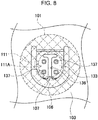
- spot welding has a characteristic of enabling reliable and stable connection of lead plate 103, and this method, as shown in an enlarged plan view of FIG. 8 , involves pressing a pair of welding electrodes against two welding points 137 formed on either side of slit 136 to avoid reactive current and passing a current between the electrodes to weld lead plate 103.
- a failure of contact with any welding point 137 hinders stable connection.
- a battery commonly called “18650” that is frequently used as a cylindrical lithium ion secondary battery in a variety of applications is formed into a circular cylinder that measures 18 mm in outside diameter and 650 mm in overall length.
- a smaller projecting electrode is disposed on an end face of the battery with an outside diameter of 18 mm, and a lead plate is connected to the projecting electrode.
- the present invention has been accomplished to solve the above problem. It is an object of the present invention to provide a battery module that allows a lead plate to be stably and reliably connected to a projecting electrode while preventing inflow of a potting resin through an outlet formed in the projecting electrode.
- a battery module includes a plurality of batteries 1 each including an outlet of a discharge valve disposed in a projecting electrode 11 on an end face of each of the plurality of batteries, a battery holder 2 arranging the batteries 1 parallel to each other at fixed positions, a lead plate 3 connected to the projecting electrode 11 of each of the batteries 1 that are arranged at the fixed positions by the battery holder 2, the end face of each of the batteries 1 being disposed on a same plane, and potting resin 13 thermally coupled to the lead plate 3.
- the discharge valve is configured to open when an internal pressure of each of the batteries 1 rises to a set pressure.
- the battery holder 2 includes an outer peripheral cover 21 having an electrode window 24 to expose the projecting electrode 11 and being disposed on a plane facing an outer peripheral edge of the projecting electrode 11.
- the lead plate 3 includes a planar part 31 disposed over a surface of the outer peripheral cover 21 and a connection recess 32 disposed in the planar part 31. The connection recess is guided into the electrode window 24 in the battery holder 2 and protrudes toward the projecting electrode 11 to connect a protrusion face 33 to the projecting electrode 11.
- a first double-sided tape 4 provides a tight fit between an outer peripheral part of each of the batteries 1 and the outer peripheral cover of the battery holder 2 to ensure that the outer peripheral part of each of the battery 1 fits tightly over the outer peripheral cover 21.
- a second double-sided tape 5 provides a tight fit between the outer peripheral cover 21 of the battery holder 2 and the planar part 31 of the lead plate 3 to ensure that the outer peripheral cover 21 fits tightly over the planar part 31 of the lead plate 3.
- a sealing label 6 is put into intimate contact with the planar part 31 of the lead plate 3 to ensure that the sealing label 6 closes an opening of the connection recess 32 of the lead plate 3.
- the first double-sided tape 4, the second double-sided tape 5, and the sealing label 6 constitute a structure that prevents the potting resin 13 from flowing into the outlet disposed in the projecting electrode 11 of each of the batteries.
- the battery module described above is characterized by allowing the lead plate to be stably and reliably connected to the projecting electrode while preventing the potting resin from flowing inside through the outlet formed in the projecting electrode. This is because the battery module is able to prevent inflow of the potting resin through the outlet without a sealing label stuck on a surface of the projecting electrode.
- the sealing label 6 is not stuck on the projecting electrode 11 but is stuck on a surface of the lead plate 3 connected to the projecting electrode 11.
- the battery module includes the first double-sided tape 4 and the second double-sided tape 5 stuck on both sides of the outer peripheral cover 21 of the battery holder 2 to prevent the potting resin 13 from flowing through any gap between an outer peripheral edge of each of the batteries 1 and the outer peripheral cover 21 of the lead plate 3.
- the battery module described above is without the sealing label stuck on the projecting electrode and is able to prevent the potting resin from flowing inside through the outlet formed in the projecting electrode by means of the sealing label and the double-sided tape.
- the battery module described above eliminates the need for precisely sticking a sealing label on an outer peripheral edge of a small projecting electrode. This makes a process of sticking a sealing label simple and effortless and enables efficient mass production of the battery module.
- the battery module allows the lead plate to be connected to a fully exposed surface of the projecting electrode and hence contributes to reliable and stable connection of the lead plate.
- the lead plate is stuck to the battery holder through the double-sided tape, and the battery holder is stuck to the end face of the electrode of the battery through the double-sided tape.
- This configuration allows the lead plate to be connected to the projecting electrode while the lead plate is temporarily fixed through the double-sided tape to avoid misalignment. This also allows the lead plate to be connected to the projecting electrode with increased reliability and stability.
- the batteries 1 may be cylindrical batteries.
- the sealing label 6 may have an external shape that covers a series of a plurality of connection recesses 32 being adjacent to each other and being connected to a plurality of projecting electrodes 11.
- the configuration described above enables a single sheet of the sealing label to close a series of the plurality of the connection recesses adjacent to each other.
- An entire area of the sealing label can be widened to cover an area including the plurality of the connection recesses and close the connection recesses, and an adhesive layer can also be disposed on an area between the connection recesses adjacent to each other.
- This enables the sealing label to display increased adhesive strength for the lead plate and reliably close the connection recesses.
- a single sheet of the sealing label closes the plurality of the connection recesses. This helps to reduce time required for manufacturing as well as manufacturing costs.
- first double-sided tape 4 may have a ring shape and may have an inside diameter substantially equal to an inside diameter of the electrode window 24 and an outside diameter substantially equal to an outside diameter of the battery 1.
- the configuration described above enables the first double-sided tape with a widened area to be put into intimate contact with the outer peripheral part of each of the batteries and the outer peripheral cover of the battery holder and provide reliable sealing.
- This configuration also enables an entire surface of the projecting electrode of the battery to be reliably exposed out of the electrode window.
- the second double-sided tape 5 may have an external shape substantially identical to an external shape of the lead plate 3, cover an area including a plurality of the electrode windows 24 opened in the battery holder 2, and include through-holes 5A that are opened at places facing the respective electrode windows 24 so as to be similar in outline to the electrode windows 24.
- the plurality of connection recesses 32 are disposed in the respective through-holes 5A.
- the configuration described above enables the second double-sided tape with a widened area to be put into intimate contact with the planar part of the lead plate and opening edges of the plurality of the electrode windows opened in the outer peripheral cover and provide reliable sealing.
- This configuration also enables the connection recesses that are disposed in the through-holes opened in the second double-sided tape to be reliably put into contact with the projecting electrodes exposed out of the respective electrode windows. Further, a single sheet of the second double-sided tape is put into intimate contact with the opening edges of the plurality of the electrode windows and the planar part of the lead plate. This helps to reduce time required for manufacturing as well as manufacturing costs.
- a single member may be configured to serve as a plurality of elements of the present invention.
- a function of a single element of the present invention may be achieved by a plurality of members.
- Contents described in some examples or in the exemplary embodiment can be used, for example, in other examples or exemplary embodiments.
- a vertical direction described in the specification is specified in the drawings.
- Battery module 10 shown in a perspective view of FIG. 3 and a plan view of FIG. 4 includes, as shown in an exploded perspective view of FIG. 5 , a plurality of batteries 1, battery holder 2 to arrange the plurality of batteries 1 parallel to one another at fixed positions, lead plates 3 to connect electrodes of batteries 1 arranged on same planes, and potting resin 13 thermally coupled to lead plates 3.
- the plurality of batteries 1 are arranged at fixed positions by battery holder 2, lead plates 3 are connected to both ends of batteries 1, and as shown in a vertical sectional view of FIG. 6 , pieces of potting resin 13 are disposed outside lead plates 3 and thermally coupled to lead plates 3 and the ends of batteries 1.
- Battery module 10 further includes first double-sided tape 4, second double-sided tape 5, and sealing labels 6 to prevent liquid or pasty potting resin 13 from permeating inside through an outlet of a discharge valve formed in projecting electrode 11 of each battery 1 while being filled with potting resin 13.
- Battery 1 has positive and negative electrodes on both ends.
- One of the electrodes constitutes projecting electrode 11 formed on a sealing plate and the other end is plane electrode 12 formed on a bottom of an exterior can.
- Battery 1 is a cylindrical lithium ion secondary battery provided with an outlet formed in projecting electrode 11.
- the lithium ion secondary battery has a large capacity relative to its size and weight and enables battery module 10 to have an increased overall capacity.
- batteries 1 for the battery module of the present invention are not limited to lithium ion secondary batteries.
- Batteries 1 may be, for example, nickel metal hydride batteries, nickelcadmium batteries, or other rechargeable batteries.
- batteries 1 are cylindrical batteries.
- the batteries may, however, be prismatic batteries.
- Lead plates 3 are welded to projecting electrodes 11 on both ends of batteries 1 by spot welding or another technique to connect adjacent batteries 1 in series or in parallel.
- Battery 1 has a discharge valve (not shown) inside the sealing plate.
- the discharge valve opens when an internal pressure of battery 1 gets higher than a set pressure and thereby prevents a case of the battery from rupturing.
- the opened discharge valve discharges an exhaust gas outside to prevent the internal pressure from rising.
- the sealing plate has an outlet on a periphery of projecting electrode 11 to discharge the exhaust gas from the opened discharge valve.
- battery 1 lets the discharge valve open to discharge an exhaust gas outside through the outlet formed on the periphery of projecting electrode 11 and prevent a rupture caused by a rise in the internal pressure.
- Battery holder 2 arranges batteries 1 parallel to one another at fixed positions such that end faces of the batteries where projecting electrodes 11 and plane electrodes 12 exist are arranged on respective same planes.
- Battery holder 2 is made by molding an insulating material such as a plastic.
- Battery holder 2 shown in FIGS. 3 and 4 includes a pair of outer peripheral covers 21 to cover both end surfaces of batteries 1, both end faces of which are arranged on the respective same planes, and insertion parts 22 that batteries 1 are inserted into and are thereby arranged at fixed positions.
- Each of the outer peripheral covers and the corresponding insertion parts are integrally molded.
- Battery holder 2 arranges batteries 1 at fixed positions such that all the batteries are parallel to one another.
- Lead plates 3 are welded to and connected to both ends of batteries 1. To make sure that planar lead plates 3 are connected to the end faces of batteries 1, battery holder 2 allows batteries 1 to be inserted into insertion parts 22 and be arranged at specified positions such that both ends of the batteries are substantially flush with respective same level surfaces.
- Battery holder 2 shown in the exploded perspective view of FIG. 5 is divided into two members on both sides of batteries 1 (divisible into two of upper and lower members in FIG. 5 ) and is molded from a plastic. Further, battery holder 2 shown in FIGS. 3 and 4 has filling room 23 in a surface of each outer peripheral cover 21 covering batteries 1. The filling room is filled with potting resin 13. In FIG. 5 , filling room 23 is formed in an upper surface of the member of battery holder 2 disposed on an upper side, and filling room 23 is formed in a lower surface of the member of battery holder 2 disposed on a lower side.
- Battery holder 2 has insertion parts 22, which batteries 1 are inserted into and are arranged at fixed positions.
- batteries 1 are cylindrical batteries, and hence insertion parts 22 are each cylindrical.
- An inside diameter of cylindrical insertion part 22 is slightly larger than an outside diameter of battery 1 to enable smooth insertion of battery 1. While the battery is being inserted into the insertion part, a tiny gap is left between a surface of battery 1 and an inner surface of insertion part 22.
- Battery holder 2 may have insertion parts 22 that are formed inside cylindrical shapes molded from a plastic or may have insertion parts 22 by molding a plastic into a block and making cylindrical through-holes inside the block.
- Battery holder 2 including the insertion parts molded from a plastic into cylindrical shapes arranges batteries 1 at fixed positions by allowing the batteries to be inserted into cylindrical insertion parts 22. This battery holder 2 is able to effectively prevent thermal runaway because adjacent batteries 1 are inserted into separately molded insertion parts 22. Battery holder 2 that allows batteries 1 to be inserted into through-hole insertion parts 22 has a large heat capacity and is thus able to absorb heat from battery 1 to prevent a rise in temperature of battery 1 and make a temperature difference between adjacent batteries 1 smaller.
- Battery holder 2 has outer peripheral covers 21 on both ends of pairs of insertion parts 22.
- the outer peripheral covers have electrode windows 24 through which the ends of batteries 1 are exposed and connected to lead plates 3.
- Electrode windows 24 each expose the end face of battery 1 inserted into insertion part 22 to an outside, i.e., a bottom of filling room 23, out of insertion part 22.
- Lead plates 3 are welded to the electrodes on both ends of each battery 1 exposed to filling rooms 23 through respective electrode windows 24.
- Lead plates 3 welded to the electrodes are disposed at the bottoms of respective filling rooms 23.
- peripheral wall 25 is formed along an outer periphery of a zone filled with potting resin 13, and the zone inside each peripheral wall 25 constitutes filling room 23.
- a thickness of potting resin 13 loaded into filling room 23 can be controlled by a height of peripheral wall 25.
- High peripheral wall 25 means that deep filling room 23 can be filled with a large amount of potting resin 13.
- a depth of filling room 23 ranges, for example, from about 1 mm to 10 mm so that potting resin 13 loaded into the filling room has a thickness to facilitate heat conduction and decrease temperature difference between adjacent batteries 1.
- Lead plates 3 are metal sheets that are connected to the ends of adjacent batteries 1 to connect batteries 1 in series or in parallel. Lead plates 3 are connected to projecting electrodes 11 and plane electrodes 12, positive and negative electrodes of batteries 1, to connect batteries 1 in series or in parallel. Lead plate 3 includes planar part 31 and connection recesses 32 formed in the planar part. Planar part 31 is disposed over a bottom surface of filling room 23 in battery holder 2, i.e., an outer surface of outer peripheral cover 21 included in battery holder 2, whereas connection recesses 32 are guided into electrode windows 24 in outer peripheral cover 21 to let protrusion faces 33 protruding toward the electrodes of batteries 1 be connected to batteries 1. Planar part 31 is present around each connection recess 32, and lead plate 3 is shaped such that openings of connection recesses 32 are closed with sealing label 6 bonded to planar part 31.
- connection recesses 32 in which connection recesses 32 are formed in planar part 31 is made by cutting a planar metal sheet and bending the cut metal sheet. Since protrusion faces 33 are connected to projecting electrodes 11 and plane electrodes 12 formed on the end faces of batteries 1, connection recesses 32 are disposed at places facing projecting electrodes 11 and plane electrodes 12 of batteries 1 that are disposed at fixed positions by battery holder 2.
- Lead plate 3 has separation slits 34 that are each formed along an outer periphery of connection recess 32. Separation slit 34 is formed partly along the outer periphery of connection recess 32, and a part of the outer periphery where no separation slit 34 is present constitutes linking part 35.
- Protrusion faces 33 are linked to planar part 31 through respective linking parts 35.
- Linking part 35 is bend and shaped such that protrusion face 33 of connection recess 32 is inserted into electrode window 24 and is put into contact with and connected to the electrode of battery 1.
- Lead plate 3 having separation slit 34 between protrusion face 33 and planar part 31 puts connection recess 32 at a deep level, or in other words, lets protrusion face 33 protrude from planar part 31 to a high degree and thereby enables the protrusion face to be connected to the electrode of battery 1.
- a lead plate does not necessarily have a separation slit on an outer peripheral edge of a connection recess and may let a protrusion face protrude from a planar part without a separation slit to enable the protrusion face to be connected to an electrode of a battery.
- Protrusion face 33 connected to the electrode of battery 1 includes welding slit 36 extending to a side away from linking part 35 and welding points 37 disposed on both sides of welding slit 36.
- the welding points are designed to be pressed by positive and negative welding electrodes and be welded to the electrode of the battery.
- lead plate 3 has two welding points 37 on either side of every welding slit 36 and a welding protrusion on each welding point 37. This structure enables the lead plate to be reliably welded to the electrode of battery 1.
- Lead plate 3 is shaped such that, when the lead plate is set in filling room 23 in battery holder 2, connection recesses 32 are guided into electrode windows 24 and the welding protrusions are put into contact with projecting electrodes 11 and plane electrodes 12 of batteries 1.
- the welding protrusions can be pressed by positive and negative welding electrodes so as to be put into contact with and be connected to the electrodes of batteries 1.
- This configuration allows protrusion faces 33 to be reliably and stably connected to the electrodes of batteries 1 by spot welding.
- the present invention is not intended to limit a way of connecting protrusion faces 33 to the electrodes of batteries 1 to spot welding. This is because the protrusion faces can be connected to the electrodes of the batteries by laser welding or ultrasonic welding.
- a process of connecting protrusion faces 33 to the electrodes of batteries 1 by laser welding involves pressing protrusion faces 33 to put the protrusion faces into contact with the electrodes of batteries 1 while the welding points are irradiated with laser beams.
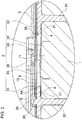
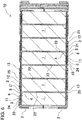
- battery module 10 To prevent potting resin 13 from permeating inside through the outlet formed in projecting electrode 11 of each battery, battery module 10, as shown in the enlarged principal part sectional views of FIGS. 1 and 2 , includes first double-sided tape 4 and second double-sided tape 5 stuck on both respective surfaces of each outer peripheral cover 21 and sealing label 6 that is stuck on a surface of each lead plate 3 so as to close connection recesses 32.
- First double-sided tape 4, second double-sided tape 5, and sealing label 6 are used to prevent potting resin 13 that has not been cured from permeating inside through the outlet formed in each projecting electrode 11 and thus are stuck on only a surface area adjacent to projecting electrodes 11 of batteries 1.
- a piece of first double-sided tape 4 has a ring shape and provides a tight fit between an outer peripheral part of battery 1, i.e., an outer peripheral part of the sealing plate that is outside projecting electrode 11, and outer peripheral cover 21 of battery holder 2.
- First double-sided tape 4 ensures that the outer peripheral part of battery 1 fits tightly over outer peripheral cover 21 of battery holder 2 without a gap to prevent potting resin 13 from permeating through any gap between the sealing plate and outer peripheral cover 21.
- First double-sided tape 4 shown in FIGS. 1 and 2 is shaped into a ring that has an inside diameter substantially equal to an inside diameter of electrode window 24 and an outside diameter substantially equal to or, more precisely, slightly smaller than the outside diameter of battery 1 to provide a tight fit between the sealing plate of battery 1 and outer peripheral cover 21.
- First double-sided tape 4 is larger than an outside diameter of projecting electrode 11 and is shaped such that a surface of projecting electrode 11 is fully exposed while the first double-sided tape is stuck on the sealing plate.
- First double-sided tape 4 is tape that includes adhesive layers on both sides, is disposed between the outer peripheral part of battery 1 and outer peripheral cover 21, and presses outer peripheral cover 21 to provide close adhesion.
- Apiece of second double-sided tape 5 provides a tight fit between outer peripheral cover 21 of battery holder 2 and planar part 31 of lead plate 3 and ensures that a surface of outer peripheral cover 21 fits tightly over planar part 31 of lead plate 3 to prevent potting resin 13 from permeating through any gap between outer peripheral cover 21 and lead plate 3.
- An external shape of second double-sided tape 5 is larger than an external shape of first double-sided tape 4. The second double-sided tape covering a large area is put into intimate contact with the surface of outer peripheral cover 21 to securely seal a joint between outer peripheral cover 21 and lead plate 3. Second double-sided tape 5 shown in FIG.
- second double-sided tape 5 has an external shape that is similar to an internal shape of filling room 23 so as to cover an area including opening edges of a plurality of electrode windows 24 opened in outer peripheral cover 21 of battery holder 2.
- the external shape of second double-sided tape 5 is made identical to an external shape of lead plate 3 such that a single piece of second double-sided tape 5 can cover overall lead plate 3.
- second double-sided tape 5 has through-holes 5A that are opened at places facing the plurality of electrode windows 24 opened in the bottom surface of filling room 23.
- Connection recesses 32 of lead plate 3 are configured to pass through through-holes 5A and be connected to projecting electrodes 11 exposed out of electrode windows 24.
- Second double-sided tape 5 is also tape that includes adhesive layers on both sides, is disposed between outer peripheral cover 21 and lead plate 3, and presses lead plate 3 to provide close adhesion.
- Sealing label 6 is tape that potting resin 13 is not allowed to pass through and that has an adhesive layer on one side. Sealing label 6 is put into intimate contact with planar part 31 of lead plate 3 so as to close the openings of connection recesses 32. Sealing label 6 is shaped such that sealing label 6 comes into intimate contact with planar part 31 adjacent to an entire periphery of each connection recess 32 and is put into intimate contact with planar part 31 to prevent potting resin 13 from flowing into connection recesses 32. Sealing label 6 in FIGS. 4 and 5 has an external shape that covers a series of a plurality of connection recesses 32 adjacent to each other so as to cover an area including the plurality of connection recesses 32 connected to projecting electrodes 11 and close the connection recesses.
- sealing label 6 shown in the drawings is a zigzag shape that enables the sealing label to close four connection recesses 34 arranged in a zigzag line at a time. Sealing label 6 is stuck on a surface of each lead plate 3 and is put into intimate contact with an entire area contiguous to the plurality of connection recesses 32 adjacent to each other to securely close the openings of connection recesses 32.
- Battery module 10 having the configuration described above is assembled through steps described below.
- a battery module of the present invention is optimally applicable to a battery module having a structure in which an end face of a battery adjacent to a discharge valve is sealed with a potting resin.
Landscapes
- Chemical & Material Sciences (AREA)
- Chemical Kinetics & Catalysis (AREA)
- Electrochemistry (AREA)
- General Chemical & Material Sciences (AREA)
- Battery Mounting, Suspending (AREA)
- Connection Of Batteries Or Terminals (AREA)
- Gas Exhaust Devices For Batteries (AREA)
Claims (5)
- Module de batterie comprenant :une pluralité de batteries comprenant chacune une sortie d'une valve de décharge disposée dans une électrode en saillie sur une face d'extrémité de chacune de la pluralité de batteries, la valve de décharge étant configurée pour s'ouvrir lorsqu'une pression interne de chacune de la pluralité de batteries, monte jusqu'à une pression de consigne ;un support de batterie agençant la pluralité de batteries parallèlement entre elles dans des positions fixes ;une plaque conductrice raccordée à l'électrode en saillie de chacune de la pluralité de batteries qui sont agencées dans des positions fixes grâce au support de batterie ; la face d'extrémité de chacune de la pluralité de batteries étant disposée sur un même plan ; etune résine d'enrobage thermiquement couplée à la plaque conductrice,dans lequel le support de batterie comprend un couvercle périphérique externe ayant une fenêtre d'électrode pour exposer l'électrode en saillie et étant disposé sur un plan faisant face à un bord périphérique externe de l'électrode en saillie,la plaque conductrice comprend :une partie planaire disposée sur une surface du couvercle périphérique externe ; etun évidement de raccordement disposé dans la partie planaire, l'évidement de raccordement étant guidé dans la fenêtre d'électrode dans le support de batterie et faisant saillie vers l'électrode en saillie pour raccorder une face de saillie de l'évidement de raccordement à l'électrode en saillie,une première bande double face fournit un ajustement avec serrage entre une partie périphérique externe de chacune de la pluralité de batteries et le couvercle périphérique externe du support de batterie afin de garantir que la partie périphérique externe de chacune de la pluralité de batteries s'adapte, avec serrage, sur le couvercle périphérique externe,une seconde bande double face fournit un ajustement avec serrage entre le couvercle périphérique externe du support de batterie et la partie planaire de la plaque conductrice afin de garantir que le couvercle périphérique s'adapte, avec serrage, sur la partie planaire de la plaque conductrice,une étiquette d'étanchéité est placée en contact immédiat avec la partie planaire de la plaque conductrice pour garantir que l'étiquette d'étanchéité ferme une ouverture de l'évidement de raccordement de la plaque conductrice, etla première bande double face, la seconde bande double face et l'étiquette d'étanchéité constituent une structure qui empêche la résine d'enrobage de s'écouler dans la sortie disposée dans l'électrode en saillie.
- Module de batterie selon la revendication 1, dans lequel chacune de la pluralité de batteries est une batterie cylindrique.
- Module de batterie selon la revendication 1 ou 2, dans lequel l'étiquette d'étanchéité a une forme externe qui recouvre une série d'une pluralité d'évidements de raccordement qui sont adjacents entre eux et étant raccordés à une pluralité d'électrodes en saillie.
- Module de batterie selon l'une quelconque des revendications 1 à 3, dans lequel la première bande double face a une forme annulaire et a un diamètre interne sensiblement égal à un diamètre interne de la fenêtre d'électrode et un diamètre externe sensiblement égal à un diamètre externe de chacune de la pluralité de batteries.
- Module de batterie selon l'une quelconque des revendications 1 à 4, dans lequel :la seconde bande double face a une forme externe sensiblement identique à une forme externe de la plaque conductrice, recouvre une zone comprenant une pluralité de fenêtres d'électrode ouvertes dans le support de batterie, et comprend des trous débouchants qui sont ouverts à des emplacements faisant face aux fenêtres d'électrode respectives afin d'être similaires du point de vue du contour à la pluralité de fenêtres d'électrode, etla pluralité d'évidements de raccordement sont disposés dans les trous débouchants respectifs.
Applications Claiming Priority (2)
| Application Number | Priority Date | Filing Date | Title |
|---|---|---|---|
| JP2017144774 | 2017-07-26 | ||
| PCT/JP2018/027415 WO2019021980A1 (fr) | 2017-07-26 | 2018-07-23 | Module de batterie |
Publications (3)
| Publication Number | Publication Date |
|---|---|
| EP3660947A1 EP3660947A1 (fr) | 2020-06-03 |
| EP3660947A4 EP3660947A4 (fr) | 2020-07-08 |
| EP3660947B1 true EP3660947B1 (fr) | 2021-09-01 |
Family
ID=65040263
Family Applications (1)
| Application Number | Title | Priority Date | Filing Date |
|---|---|---|---|
| EP18839174.2A Active EP3660947B1 (fr) | 2017-07-26 | 2018-07-23 | Module de batterie |
Country Status (6)
| Country | Link |
|---|---|
| US (1) | US11276906B2 (fr) |
| EP (1) | EP3660947B1 (fr) |
| JP (1) | JP7160808B2 (fr) |
| AU (1) | AU2018307012B2 (fr) |
| NZ (1) | NZ761684A (fr) |
| WO (1) | WO2019021980A1 (fr) |
Families Citing this family (25)
| Publication number | Priority date | Publication date | Assignee | Title |
|---|---|---|---|---|
| WO2018022964A1 (fr) | 2016-07-29 | 2018-02-01 | Crynamt Management Llc | Blocs-batteries ayant des éléments structuraux pour améliorer la gestion thermique |
| US11757149B1 (en) | 2016-09-20 | 2023-09-12 | Apple Inc. | Battery liquid quench system and methods of manufacture thereof |
| US10923788B1 (en) | 2016-11-30 | 2021-02-16 | Apple Inc. | Directed quench systems and components |
| US11870092B1 (en) | 2017-02-01 | 2024-01-09 | Apple Inc. | On-board vent gas abatement |
| US11469471B1 (en) | 2018-02-02 | 2022-10-11 | Apple Inc. | Battery pack heat dispensing systems |
| KR102828348B1 (ko) * | 2019-09-09 | 2025-07-03 | 삼성에스디아이 주식회사 | 배터리 팩 |
| KR102828349B1 (ko) | 2019-09-09 | 2025-07-03 | 삼성에스디아이 주식회사 | 배터리 팩 |
| KR102572650B1 (ko) * | 2019-11-29 | 2023-08-31 | 삼성에스디아이 주식회사 | 배터리 팩 |
| KR102561801B1 (ko) | 2019-11-29 | 2023-07-31 | 삼성에스디아이 주식회사 | 배터리 팩 |
| KR20210067647A (ko) | 2019-11-29 | 2021-06-08 | 삼성에스디아이 주식회사 | 배터리 팩 |
| KR102574517B1 (ko) | 2019-11-29 | 2023-09-04 | 삼성에스디아이 주식회사 | 배터리 팩 |
| KR102533159B1 (ko) | 2019-11-29 | 2023-05-17 | 삼성에스디아이 주식회사 | 배터리 팩 |
| KR102501080B1 (ko) | 2019-11-29 | 2023-02-17 | 삼성에스디아이 주식회사 | 배터리 팩 |
| US11764431B2 (en) | 2020-10-22 | 2023-09-19 | Apple Inc. | Battery pack structures and systems |
| JP7633288B2 (ja) * | 2021-02-09 | 2025-02-19 | エルジー エナジー ソリューション リミテッド | バッテリーモジュール、それを含むバッテリーパック及び自動車 |
| EP4322312A4 (fr) * | 2021-05-06 | 2025-03-05 | LG Energy Solution, Ltd. | Ensemble barre omnibus, bloc-batterie le comprenant et automobile |
| KR102598325B1 (ko) * | 2021-07-13 | 2023-11-02 | (주)코미트 | 원형니켈단자가 표면실장된 전극결합판을 갖는 직병렬 리튬이온배터리팩 |
| US12009655B2 (en) | 2021-09-15 | 2024-06-11 | Apple Inc. | Switchable pyro fuse |
| JP7652914B2 (ja) * | 2021-12-16 | 2025-03-27 | エルジー エナジー ソリューション リミテッド | 安全性が向上したバッテリーモジュール |
| EP4550561A4 (fr) * | 2022-06-30 | 2025-10-22 | Panasonic Energy Co Ltd | Bloc-batterie |
| CN115621648B (zh) * | 2022-11-07 | 2024-08-27 | 哈尔滨理工大学 | 一种双凸极电池连接结构及电池模块 |
| KR20240155809A (ko) * | 2023-04-20 | 2024-10-29 | 주식회사 엘지에너지솔루션 | 배터리모듈 및 이를 포함하는 배터리팩 |
| WO2024219873A1 (fr) * | 2023-04-20 | 2024-10-24 | 주식회사 엘지에너지솔루션 | Module de batterie et bloc-batterie le comprenant |
| DE102023111889A1 (de) * | 2023-05-08 | 2024-11-14 | Bayerische Motoren Werke Aktiengesellschaft | Elektrischer Energiespeicher für ein Kraftfahrzeug, insbesondere für einen Kraftwagen, sowie Kraftfahrzeug |
| US20260112751A1 (en) * | 2024-10-17 | 2026-04-23 | Toyota Jidosha Kabushiki Kaisha | Power storage device, and manufacturing method and inspection method thereof |
Family Cites Families (7)
| Publication number | Priority date | Publication date | Assignee | Title |
|---|---|---|---|---|
| JP4601432B2 (ja) | 2005-01-12 | 2010-12-22 | 三洋電機株式会社 | パック電池 |
| JP5173227B2 (ja) * | 2007-03-30 | 2013-04-03 | 三洋電機株式会社 | パック電池 |
| JP2012054121A (ja) * | 2010-09-02 | 2012-03-15 | Sanyo Electric Co Ltd | 電池パック |
| JP5341156B2 (ja) | 2011-09-06 | 2013-11-13 | 三洋電機株式会社 | 電源装置 |
| WO2014184993A1 (fr) * | 2013-05-15 | 2014-11-20 | 三洋電機株式会社 | Bloc-batterie et procédé de fabrication de bloc-batterie |
| JP5831608B2 (ja) * | 2014-08-29 | 2015-12-09 | ソニー株式会社 | 電池ユニット |
| JP2018106796A (ja) | 2015-05-07 | 2018-07-05 | 三洋電機株式会社 | 電池パック及び電池パックの製造方法 |
-
2018
- 2018-07-23 EP EP18839174.2A patent/EP3660947B1/fr active Active
- 2018-07-23 NZ NZ761684A patent/NZ761684A/en unknown
- 2018-07-23 AU AU2018307012A patent/AU2018307012B2/en active Active
- 2018-07-23 US US16/633,019 patent/US11276906B2/en active Active
- 2018-07-23 JP JP2019532579A patent/JP7160808B2/ja active Active
- 2018-07-23 WO PCT/JP2018/027415 patent/WO2019021980A1/fr not_active Ceased
Also Published As
| Publication number | Publication date |
|---|---|
| EP3660947A4 (fr) | 2020-07-08 |
| EP3660947A1 (fr) | 2020-06-03 |
| JPWO2019021980A1 (ja) | 2020-05-28 |
| US20200220147A1 (en) | 2020-07-09 |
| US11276906B2 (en) | 2022-03-15 |
| AU2018307012A1 (en) | 2020-02-27 |
| JP7160808B2 (ja) | 2022-10-25 |
| AU2018307012B2 (en) | 2024-02-22 |
| WO2019021980A1 (fr) | 2019-01-31 |
| NZ761684A (en) | 2026-01-30 |
Similar Documents
| Publication | Publication Date | Title |
|---|---|---|
| EP3660947B1 (fr) | Module de batterie | |
| CN101048890B (zh) | 锁定型电池包 | |
| EP1744384B1 (fr) | Batterie secondaire de type stratifiée et bloc de batterie à partir de celle-ci | |
| CN108389983B (zh) | 多功能离子袋状电池单元框架 | |
| RU2355070C1 (ru) | Аккумуляторный источник питания очень малой толщины | |
| EP1501141B1 (fr) | Separateur destine a une pile a combustible | |
| JP2007157678A (ja) | ラミネート電池の安全機構 | |
| CN101540381A (zh) | 帽组件和使用该帽组件的蓄电池 | |
| CN106611864B (zh) | 燃料电池用带树脂框的电解质膜-电极构造体 | |
| US20150104700A1 (en) | Sealed battery and method for manufacturing the same | |
| KR20200132294A (ko) | 연료전지용 탄성체 셀 프레임 및 그 제조방법과 이를 이용한 연료전지 스택 | |
| EP3555935B1 (fr) | Boîtier de module de batterie, module de batterie et batterie | |
| JP7067300B2 (ja) | 電池モジュール及び電池モジュールの製造方法 | |
| JPWO2017104212A1 (ja) | 燃料電池スタックのシール構造及びその製造方法 | |
| CN120883433A (zh) | 通过加强件来简化爆破膜的组装 | |
| KR101142682B1 (ko) | 배터리 팩 | |
| JP4091769B2 (ja) | 角形密閉式電池 | |
| KR20200077304A (ko) | 비대칭 형태의 오목부를 포함하는 파우치형 전지케이스 | |
| JP2013251123A (ja) | 角形二次電池 | |
| JP7103033B2 (ja) | 蓄電モジュール及び蓄電モジュールの製造方法 | |
| JP4172350B2 (ja) | 燃料電池セパレータ | |
| CN114824412A (zh) | 二次电池和电池组 | |
| JP7764949B2 (ja) | 電池パック | |
| CN223193922U (zh) | 电池壳体和电池装置 | |
| CN223871472U (zh) | 锂离子电池 |
Legal Events
| Date | Code | Title | Description |
|---|---|---|---|
| STAA | Information on the status of an ep patent application or granted ep patent |
Free format text: STATUS: THE INTERNATIONAL PUBLICATION HAS BEEN MADE |
|
| PUAI | Public reference made under article 153(3) epc to a published international application that has entered the european phase |
Free format text: ORIGINAL CODE: 0009012 |
|
| STAA | Information on the status of an ep patent application or granted ep patent |
Free format text: STATUS: REQUEST FOR EXAMINATION WAS MADE |
|
| 17P | Request for examination filed |
Effective date: 20200213 |
|
| AK | Designated contracting states |
Kind code of ref document: A1 Designated state(s): AL AT BE BG CH CY CZ DE DK EE ES FI FR GB GR HR HU IE IS IT LI LT LU LV MC MK MT NL NO PL PT RO RS SE SI SK SM TR |
|
| AX | Request for extension of the european patent |
Extension state: BA ME |
|
| A4 | Supplementary search report drawn up and despatched |
Effective date: 20200605 |
|
| RIC1 | Information provided on ipc code assigned before grant |
Ipc: H01M 2/20 20060101ALI20200529BHEP Ipc: H01M 2/34 20060101ALI20200529BHEP Ipc: H01M 2/22 20060101ALI20200529BHEP Ipc: H01M 2/12 20060101ALI20200529BHEP Ipc: H01M 2/10 20060101AFI20200529BHEP |
|
| DAV | Request for validation of the european patent (deleted) | ||
| DAX | Request for extension of the european patent (deleted) | ||
| REG | Reference to a national code |
Ref country code: DE Ref legal event code: R079 Ref document number: 602018023060 Country of ref document: DE Free format text: PREVIOUS MAIN CLASS: H01M0002100000 Ipc: H01M0050213000 |
|
| GRAP | Despatch of communication of intention to grant a patent |
Free format text: ORIGINAL CODE: EPIDOSNIGR1 |
|
| STAA | Information on the status of an ep patent application or granted ep patent |
Free format text: STATUS: GRANT OF PATENT IS INTENDED |
|
| RIC1 | Information provided on ipc code assigned before grant |
Ipc: H01M 50/578 20210101ALI20210315BHEP Ipc: H01M 50/528 20210101ALI20210315BHEP Ipc: H01M 50/502 20210101ALI20210315BHEP Ipc: H01M 50/30 20210101ALI20210315BHEP Ipc: H01M 50/213 20210101AFI20210315BHEP |
|
| INTG | Intention to grant announced |
Effective date: 20210406 |
|
| GRAS | Grant fee paid |
Free format text: ORIGINAL CODE: EPIDOSNIGR3 |
|
| GRAA | (expected) grant |
Free format text: ORIGINAL CODE: 0009210 |
|
| STAA | Information on the status of an ep patent application or granted ep patent |
Free format text: STATUS: THE PATENT HAS BEEN GRANTED |
|
| AK | Designated contracting states |
Kind code of ref document: B1 Designated state(s): AL AT BE BG CH CY CZ DE DK EE ES FI FR GB GR HR HU IE IS IT LI LT LU LV MC MK MT NL NO PL PT RO RS SE SI SK SM TR |
|
| REG | Reference to a national code |
Ref country code: GB Ref legal event code: FG4D |
|
| RIN1 | Information on inventor provided before grant (corrected) |
Inventor name: FUKUSHIMA KOUJI Inventor name: MURAMATSU KOICHI Inventor name: HAINO MASAMI |
|
| REG | Reference to a national code |
Ref country code: CH Ref legal event code: EP Ref country code: AT Ref legal event code: REF Ref document number: 1427170 Country of ref document: AT Kind code of ref document: T Effective date: 20210915 |
|
| REG | Reference to a national code |
Ref country code: DE Ref legal event code: R096 Ref document number: 602018023060 Country of ref document: DE |
|
| REG | Reference to a national code |
Ref country code: IE Ref legal event code: FG4D |
|
| REG | Reference to a national code |
Ref country code: LT Ref legal event code: MG9D |
|
| REG | Reference to a national code |
Ref country code: NL Ref legal event code: MP Effective date: 20210901 |
|
| PG25 | Lapsed in a contracting state [announced via postgrant information from national office to epo] |
Ref country code: LT Free format text: LAPSE BECAUSE OF FAILURE TO SUBMIT A TRANSLATION OF THE DESCRIPTION OR TO PAY THE FEE WITHIN THE PRESCRIBED TIME-LIMIT Effective date: 20210901 Ref country code: BG Free format text: LAPSE BECAUSE OF FAILURE TO SUBMIT A TRANSLATION OF THE DESCRIPTION OR TO PAY THE FEE WITHIN THE PRESCRIBED TIME-LIMIT Effective date: 20211201 Ref country code: HR Free format text: LAPSE BECAUSE OF FAILURE TO SUBMIT A TRANSLATION OF THE DESCRIPTION OR TO PAY THE FEE WITHIN THE PRESCRIBED TIME-LIMIT Effective date: 20210901 Ref country code: NO Free format text: LAPSE BECAUSE OF FAILURE TO SUBMIT A TRANSLATION OF THE DESCRIPTION OR TO PAY THE FEE WITHIN THE PRESCRIBED TIME-LIMIT Effective date: 20211201 Ref country code: SE Free format text: LAPSE BECAUSE OF FAILURE TO SUBMIT A TRANSLATION OF THE DESCRIPTION OR TO PAY THE FEE WITHIN THE PRESCRIBED TIME-LIMIT Effective date: 20210901 Ref country code: RS Free format text: LAPSE BECAUSE OF FAILURE TO SUBMIT A TRANSLATION OF THE DESCRIPTION OR TO PAY THE FEE WITHIN THE PRESCRIBED TIME-LIMIT Effective date: 20210901 Ref country code: FI Free format text: LAPSE BECAUSE OF FAILURE TO SUBMIT A TRANSLATION OF THE DESCRIPTION OR TO PAY THE FEE WITHIN THE PRESCRIBED TIME-LIMIT Effective date: 20210901 Ref country code: ES Free format text: LAPSE BECAUSE OF FAILURE TO SUBMIT A TRANSLATION OF THE DESCRIPTION OR TO PAY THE FEE WITHIN THE PRESCRIBED TIME-LIMIT Effective date: 20210901 |
|
| REG | Reference to a national code |
Ref country code: AT Ref legal event code: MK05 Ref document number: 1427170 Country of ref document: AT Kind code of ref document: T Effective date: 20210901 |
|
| PG25 | Lapsed in a contracting state [announced via postgrant information from national office to epo] |
Ref country code: PL Free format text: LAPSE BECAUSE OF FAILURE TO SUBMIT A TRANSLATION OF THE DESCRIPTION OR TO PAY THE FEE WITHIN THE PRESCRIBED TIME-LIMIT Effective date: 20210901 Ref country code: LV Free format text: LAPSE BECAUSE OF FAILURE TO SUBMIT A TRANSLATION OF THE DESCRIPTION OR TO PAY THE FEE WITHIN THE PRESCRIBED TIME-LIMIT Effective date: 20210901 Ref country code: GR Free format text: LAPSE BECAUSE OF FAILURE TO SUBMIT A TRANSLATION OF THE DESCRIPTION OR TO PAY THE FEE WITHIN THE PRESCRIBED TIME-LIMIT Effective date: 20211202 |
|
| PG25 | Lapsed in a contracting state [announced via postgrant information from national office to epo] |
Ref country code: AT Free format text: LAPSE BECAUSE OF FAILURE TO SUBMIT A TRANSLATION OF THE DESCRIPTION OR TO PAY THE FEE WITHIN THE PRESCRIBED TIME-LIMIT Effective date: 20210901 |
|
| PG25 | Lapsed in a contracting state [announced via postgrant information from national office to epo] |
Ref country code: IS Free format text: LAPSE BECAUSE OF FAILURE TO SUBMIT A TRANSLATION OF THE DESCRIPTION OR TO PAY THE FEE WITHIN THE PRESCRIBED TIME-LIMIT Effective date: 20220101 Ref country code: SM Free format text: LAPSE BECAUSE OF FAILURE TO SUBMIT A TRANSLATION OF THE DESCRIPTION OR TO PAY THE FEE WITHIN THE PRESCRIBED TIME-LIMIT Effective date: 20210901 Ref country code: SK Free format text: LAPSE BECAUSE OF FAILURE TO SUBMIT A TRANSLATION OF THE DESCRIPTION OR TO PAY THE FEE WITHIN THE PRESCRIBED TIME-LIMIT Effective date: 20210901 Ref country code: RO Free format text: LAPSE BECAUSE OF FAILURE TO SUBMIT A TRANSLATION OF THE DESCRIPTION OR TO PAY THE FEE WITHIN THE PRESCRIBED TIME-LIMIT Effective date: 20210901 Ref country code: PT Free format text: LAPSE BECAUSE OF FAILURE TO SUBMIT A TRANSLATION OF THE DESCRIPTION OR TO PAY THE FEE WITHIN THE PRESCRIBED TIME-LIMIT Effective date: 20220103 Ref country code: NL Free format text: LAPSE BECAUSE OF FAILURE TO SUBMIT A TRANSLATION OF THE DESCRIPTION OR TO PAY THE FEE WITHIN THE PRESCRIBED TIME-LIMIT Effective date: 20210901 Ref country code: EE Free format text: LAPSE BECAUSE OF FAILURE TO SUBMIT A TRANSLATION OF THE DESCRIPTION OR TO PAY THE FEE WITHIN THE PRESCRIBED TIME-LIMIT Effective date: 20210901 Ref country code: CZ Free format text: LAPSE BECAUSE OF FAILURE TO SUBMIT A TRANSLATION OF THE DESCRIPTION OR TO PAY THE FEE WITHIN THE PRESCRIBED TIME-LIMIT Effective date: 20210901 Ref country code: AL Free format text: LAPSE BECAUSE OF FAILURE TO SUBMIT A TRANSLATION OF THE DESCRIPTION OR TO PAY THE FEE WITHIN THE PRESCRIBED TIME-LIMIT Effective date: 20210901 |
|
| REG | Reference to a national code |
Ref country code: DE Ref legal event code: R097 Ref document number: 602018023060 Country of ref document: DE |
|
| PLBE | No opposition filed within time limit |
Free format text: ORIGINAL CODE: 0009261 |
|
| STAA | Information on the status of an ep patent application or granted ep patent |
Free format text: STATUS: NO OPPOSITION FILED WITHIN TIME LIMIT |
|
| PG25 | Lapsed in a contracting state [announced via postgrant information from national office to epo] |
Ref country code: DK Free format text: LAPSE BECAUSE OF FAILURE TO SUBMIT A TRANSLATION OF THE DESCRIPTION OR TO PAY THE FEE WITHIN THE PRESCRIBED TIME-LIMIT Effective date: 20210901 |
|
| 26N | No opposition filed |
Effective date: 20220602 |
|
| PG25 | Lapsed in a contracting state [announced via postgrant information from national office to epo] |
Ref country code: SI Free format text: LAPSE BECAUSE OF FAILURE TO SUBMIT A TRANSLATION OF THE DESCRIPTION OR TO PAY THE FEE WITHIN THE PRESCRIBED TIME-LIMIT Effective date: 20210901 |
|
| PG25 | Lapsed in a contracting state [announced via postgrant information from national office to epo] |
Ref country code: MC Free format text: LAPSE BECAUSE OF FAILURE TO SUBMIT A TRANSLATION OF THE DESCRIPTION OR TO PAY THE FEE WITHIN THE PRESCRIBED TIME-LIMIT Effective date: 20210901 |
|
| REG | Reference to a national code |
Ref country code: CH Ref legal event code: PL |
|
| GBPC | Gb: european patent ceased through non-payment of renewal fee |
Effective date: 20220723 |
|
| REG | Reference to a national code |
Ref country code: BE Ref legal event code: MM Effective date: 20220731 |
|
| PG25 | Lapsed in a contracting state [announced via postgrant information from national office to epo] |
Ref country code: LU Free format text: LAPSE BECAUSE OF NON-PAYMENT OF DUE FEES Effective date: 20220723 Ref country code: CH Free format text: LAPSE BECAUSE OF NON-PAYMENT OF DUE FEES Effective date: 20220731 Ref country code: LI Free format text: LAPSE BECAUSE OF NON-PAYMENT OF DUE FEES Effective date: 20220731 |
|
| PG25 | Lapsed in a contracting state [announced via postgrant information from national office to epo] |
Ref country code: GB Free format text: LAPSE BECAUSE OF NON-PAYMENT OF DUE FEES Effective date: 20220723 Ref country code: BE Free format text: LAPSE BECAUSE OF NON-PAYMENT OF DUE FEES Effective date: 20220731 |
|
| PG25 | Lapsed in a contracting state [announced via postgrant information from national office to epo] |
Ref country code: IE Free format text: LAPSE BECAUSE OF NON-PAYMENT OF DUE FEES Effective date: 20220723 |
|
| P01 | Opt-out of the competence of the unified patent court (upc) registered |
Effective date: 20230808 |
|
| PG25 | Lapsed in a contracting state [announced via postgrant information from national office to epo] |
Ref country code: MK Free format text: LAPSE BECAUSE OF FAILURE TO SUBMIT A TRANSLATION OF THE DESCRIPTION OR TO PAY THE FEE WITHIN THE PRESCRIBED TIME-LIMIT Effective date: 20210901 Ref country code: CY Free format text: LAPSE BECAUSE OF FAILURE TO SUBMIT A TRANSLATION OF THE DESCRIPTION OR TO PAY THE FEE WITHIN THE PRESCRIBED TIME-LIMIT Effective date: 20210901 |
|
| PG25 | Lapsed in a contracting state [announced via postgrant information from national office to epo] |
Ref country code: HU Free format text: LAPSE BECAUSE OF FAILURE TO SUBMIT A TRANSLATION OF THE DESCRIPTION OR TO PAY THE FEE WITHIN THE PRESCRIBED TIME-LIMIT; INVALID AB INITIO Effective date: 20180723 |
|
| PG25 | Lapsed in a contracting state [announced via postgrant information from national office to epo] |
Ref country code: MT Free format text: LAPSE BECAUSE OF FAILURE TO SUBMIT A TRANSLATION OF THE DESCRIPTION OR TO PAY THE FEE WITHIN THE PRESCRIBED TIME-LIMIT Effective date: 20210901 |
|
| REG | Reference to a national code |
Ref country code: DE Ref legal event code: R081 Ref document number: 602018023060 Country of ref document: DE Owner name: PANASONIC ENERGY CO., LTD., MORIGUCHI-SHI, JP Free format text: FORMER OWNER: SANYO ELECTRIC CO., LTD., DAITO-SHI, OSAKA, JP |
|
| PGFP | Annual fee paid to national office [announced via postgrant information from national office to epo] |
Ref country code: DE Payment date: 20250722 Year of fee payment: 8 |
|
| PGFP | Annual fee paid to national office [announced via postgrant information from national office to epo] |
Ref country code: IT Payment date: 20250724 Year of fee payment: 8 |
|
| PGFP | Annual fee paid to national office [announced via postgrant information from national office to epo] |
Ref country code: FR Payment date: 20250725 Year of fee payment: 8 |
|
| PG25 | Lapsed in a contracting state [announced via postgrant information from national office to epo] |
Ref country code: TR Free format text: LAPSE BECAUSE OF FAILURE TO SUBMIT A TRANSLATION OF THE DESCRIPTION OR TO PAY THE FEE WITHIN THE PRESCRIBED TIME-LIMIT Effective date: 20210901 |