EP3661022B1 - Structure de rotor stratifiée pour une machine synchrone à aimant permanent - Google Patents
Structure de rotor stratifiée pour une machine synchrone à aimant permanent Download PDFInfo
- Publication number
- EP3661022B1 EP3661022B1 EP20152437.8A EP20152437A EP3661022B1 EP 3661022 B1 EP3661022 B1 EP 3661022B1 EP 20152437 A EP20152437 A EP 20152437A EP 3661022 B1 EP3661022 B1 EP 3661022B1
- Authority
- EP
- European Patent Office
- Prior art keywords
- rotor
- permanent magnets
- disposed
- pair
- magnets
- Prior art date
- Legal status (The legal status is an assumption and is not a legal conclusion. Google has not performed a legal analysis and makes no representation as to the accuracy of the status listed.)
- Active
Links
Images

Classifications
-
- H—ELECTRICITY
- H02—GENERATION; CONVERSION OR DISTRIBUTION OF ELECTRIC POWER
- H02K—DYNAMO-ELECTRIC MACHINES
- H02K9/00—Arrangements for cooling or ventilating
- H02K9/02—Arrangements for cooling or ventilating by ambient air flowing through the machine
- H02K9/04—Arrangements for cooling or ventilating by ambient air flowing through the machine having means for generating a flow of cooling medium
- H02K9/06—Arrangements for cooling or ventilating by ambient air flowing through the machine having means for generating a flow of cooling medium with fans or impellers driven by the machine shaft
-
- H—ELECTRICITY
- H02—GENERATION; CONVERSION OR DISTRIBUTION OF ELECTRIC POWER
- H02K—DYNAMO-ELECTRIC MACHINES
- H02K1/00—Details of the magnetic circuit
- H02K1/06—Details of the magnetic circuit characterised by the shape, form or construction
- H02K1/22—Rotating parts of the magnetic circuit
- H02K1/223—Rotor cores with windings and permanent magnets
-
- H—ELECTRICITY
- H02—GENERATION; CONVERSION OR DISTRIBUTION OF ELECTRIC POWER
- H02K—DYNAMO-ELECTRIC MACHINES
- H02K1/00—Details of the magnetic circuit
- H02K1/06—Details of the magnetic circuit characterised by the shape, form or construction
- H02K1/22—Rotating parts of the magnetic circuit
- H02K1/27—Rotor cores with permanent magnets
- H02K1/2706—Inner rotors
- H02K1/272—Inner rotors the magnetisation axis of the magnets being perpendicular to the rotor axis
- H02K1/274—Inner rotors the magnetisation axis of the magnets being perpendicular to the rotor axis the rotor consisting of two or more circumferentially positioned magnets
- H02K1/2753—Inner rotors the magnetisation axis of the magnets being perpendicular to the rotor axis the rotor consisting of two or more circumferentially positioned magnets the rotor consisting of magnets or groups of magnets arranged with alternating polarity
- H02K1/276—Magnets embedded in the magnetic core, e.g. interior permanent magnets [IPM]
- H02K1/2766—Magnets embedded in the magnetic core, e.g. interior permanent magnets [IPM] having a flux concentration effect
-
- H—ELECTRICITY
- H02—GENERATION; CONVERSION OR DISTRIBUTION OF ELECTRIC POWER
- H02K—DYNAMO-ELECTRIC MACHINES
- H02K1/00—Details of the magnetic circuit
- H02K1/06—Details of the magnetic circuit characterised by the shape, form or construction
- H02K1/22—Rotating parts of the magnetic circuit
- H02K1/32—Rotating parts of the magnetic circuit with channels or ducts for flow of cooling medium
-
- H—ELECTRICITY
- H02—GENERATION; CONVERSION OR DISTRIBUTION OF ELECTRIC POWER
- H02K—DYNAMO-ELECTRIC MACHINES
- H02K9/00—Arrangements for cooling or ventilating
- H02K9/02—Arrangements for cooling or ventilating by ambient air flowing through the machine
Definitions
- the invention relates to a laminated rotor structure of a rotor for a permanent magnet synchronous machine as defined in the preamble of claim 1.
- the permanent magnets are disposed inside the rotor body in a ring-type V-shape configuration known per se, i.e. the first ends of the permanent magnets are close to the surface of the rotor and the second ends are closer to the central axis but disposed at an angle to the radial direction.
- every second magnet is inclined in one direction and every second in the other direction relative to the radial direction.
- This type of structure has been disclosed in publication JP 2006050821 . The purpose of said structure has been to minimize the leakage flux and at the same time to achieve sufficient rigidity of the rotor when using permanent magnets that are embedded in the rotor.
- patent US 4445062 Another structure representing the prior art has been disclosed in patent US 4445062 . It features permanent magnet rods embedded in the rotor, in radial grooves on the surface thereof, in such a way that the poles of the permanent magnets are disposed one after the other in the circumferential direction.
- the bottom of a groove is so dimensioned or shaped relative to the permanent magnet as to form on the bottom of the groove a gap that can act as a cooling air channel that extends axially through the rotor.
- the purpose of the structure is simply and securely to fix the magnets in place in the rotor.
- the publication does not discuss minimization of the leakage flux of the magnets.
- the ferromagnetic disk pack constitutes a good body for the rotor around the magnets, but heating of the rotor and particularly of the magnets causes problems specifically in large machines. Another problem is the leakage flux of the rotor and the armature reaction, i.e. the magnetic flux tends to move sideways on the rotor pole, which is not a desirable phenomenon.
- Publication WO2010047657 describes an electric motor that comprises a stator and a rotor of hybrid type.
- the rotor comprises a rotor core comprising an annular radially outer section of asynchronous type and an annular radially inner section of synchronous type arranged radially inside said outer section.
- Publication JP2009195088 describes a permanent magnet rotor having a core formed by stacking a plurality of electromagnetic steel plates.
- a through-hole is formed outward from a position where a permanent magnet is embedded to extend in a shaft direction.
- a cylindrical fastening member for fastening the electromagnetic steel plates in cooperation with the end plates is arranged to penetrate through the through-hole.
- a first communicating hole communicating to the inside of the cylindrical fastening member is formed on one of the end plates, and a gap between the inner surface of the through-hole and the cylindrical fastening member is filled with a resin supplied from the first communicating hole and entering the gap by a suction action from a second communicating hole via a hole formed on the cylindrical fastening member.
- Publication US4445062 describes a rotor assembly that comprises wedge-shaped permanent magnets and anchors with undulating sides for attaching a rotor hub to pole bodies.
- Publication JP2010193660 describes a core of a rotor that is split into outer circumferential side core pieces relatively positioned on an outer circumference of the rotor, and a rotary shaft side core piece relatively positioned on the rotary shaft side of the rotor.
- the outer circumferential side core pieces and the rotary shaft side core are fitted to core piece coupling members between two permanent magnets configuring a same pole.
- the objective of the invention is to remedy the defects of the prior art referred to above.
- the objective of the invention is to disclose a novel laminate rotor structure wherein the excessive heating of the magnets has been prevented and wherein the magnetic fluxes are made to move in an optimal fashion, minimizing the leakage fluxes.
- a new laminated rotor structure of a rotor for a permanent magnet synchronous machine is provided.
- the laminated rotor structure of the rotor is defined in an accompanying independent claim.
- the laminated rotor structure of the rotor according to the invention provides considerable advantages as compared to the prior art.
- the temperature of the rotor and, most importantly, of the magnets therein can be kept within allowable limits to maintain their magnetic properties.
- the magnetic flux is made to move in the rotor structure in an optimal fashion by virtue of properly placed flux blocks, minimizing leakage fluxes of the permanent magnets, which has a considerable effect on the size of the electric machine.
- the rotor is made mechanically robust by virtue of the inventive structure.
- a laminated rotor structure of a rotor according to an exemplifying embodiment is defined in an accompanying dependent claim.
- Fig. 1 presents the structure of a rotor that has been laminated from ferromagnetic disks in a permanent magnet synchronous machine. More specifically, a sectional view of a sector delimited by dash lines, including one V-shaped pair of permanent magnets. There are a number of these kinds of sectors present in the rotor, for example at least eight or even much more.
- the rotor thus consists of a large number of ferromagnetic round disks tightly disposed side by side as a single pack in the axial direction of the rotor.
- the structures included in the sector extend axially, identically and unchangeably, through the entire disk pack structure of the rotor.
- In proximity to the surface 2 of a disk 1 inside the rotor there are a number of generally copper-made bars 3 of a damper winding, connected in a manner known per se to copper short-circuiting rings disposed at each end of the rotor.
- Two permanent magnets 4 are disposed at an angle ⁇ to each other so that the first ends 5 of the magnets are disposed at a distance from each other close to the outer surface 2 of the rotor and the second ends 6 are disposed closer to the shaft of the rotor adjacent to each other but not entirely engaged to each other.
- the angle ⁇ between the magnets 4 that opens outward encompasses a support structure formed by two non-ferromagnetic support bolts 11 mounted in the radial direction on the bisector of the angle ⁇ and by an air gap 12 to connect them, having a width that is smaller than the diameter of the bolts.
- the support bolts and the air gap together constitute a non-ferromagnetic structure that directs the magnetic flux in the area of the angle ⁇ to the radial direction of the rotor.
- the air channel system 7 is formed by two subchannels 9, and between the subchannels there is a radial neck 8 disposed in the direction of the bisector of the angle ⁇ that is made of the same monolithic material as the disk 1.
- the subchannels 9 are so shaped as to be in direct heat transfer communication to the second end 6 of the respective magnet 4 over a specific segment 13 of the end of the magnet.
- the purpose of the neck 8 made from the material of the disk 1 is effectively to direct the magnetic flux around the subchannels 9 in order to minimize the leakage flux.
- Another purpose of the neck 8 is mechanically to support the rotor structure in the radial direction, as the strong centrifugal forces that act on the magnets 4 and the bars 3 could damage the rotor without the neck 8 giving support to the structure.
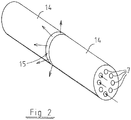
- Fig. 2 presents one embodiment of the invention wherein the rotor having a laminate structure consists of two subrotors 14 that are disposed axially one after the other.
- the subrotors are mechanically and fixedly joined together to form a jointly operating assembly, while having a radial gap 15 therebetween.
- the gap 15 extends to the outer surface of the rotor from the air channel systems 7 that run axially inside the rotor from one end to the other.
- the subrotors 14 may even be fixedly mounted to each other in the rotor inward from the air channel systems 7.
- the air channel systems 7 act as air supply channels for the radial gap or gaps 15 that effectively supply in the radial direction the air flow that flows axially through the rotor to the stator as the cooling air it needs.
- the cooling flow is provided in this structure effectively and even in the correct order because the rotor that is more critical in terms of excessive heating is cooled first, and the stator is cooled thereafter by the same air flow.
- the radial gap and any possible blades or corresponding members therein constitute an effective centrifugal blower by which the cooling of the rotor and the stator is carried out effectively.
Landscapes
- Engineering & Computer Science (AREA)
- Power Engineering (AREA)
- Permanent Field Magnets Of Synchronous Machinery (AREA)
- Iron Core Of Rotating Electric Machines (AREA)
Claims (2)
- Structure de rotor laminée d'un rotor pour une machine synchrone à aimants permanents, la structure de rotor laminée comprenant des disques (1) de matériau ferromagnétique constituant un corps du rotor qui incluent des barres (3) d'un bobinage amortisseur s'étendant axialement tout près d'une surface extérieure (2) du rotor, d'une extrémité du corps du rotor vers une autre extrémité du corps du rotor, et un cercle d'aimants permanents (4) agencés pour constituer des paires d'aimants permanents de façon à ce que les aimants permanents de chaque paire d'aimants permanents soient disposés dans une configuration en V formant une zone en V tout près d'un périmètre extérieur du rotor et entre les deux aimants de chaque paire d'aimants permanents à l'intérieur d'un cercle formé par les barres, dans laquelle des premières extrémités (5) des aimants permanents de chaque paire d'aimants permanents sont disposées tout près du périmètre extérieur du rotor et des secondes extrémités (6) des aimants permanents de chaque paire d'aimants permanents sont disposées plus près d'un axe central du rotor que les premières extrémités des aimants permanents, et dans laquelle les aimants permanents de chaque paire d'aimants permanents sont disposés à un angle (α) l'un par rapport à l'autre de façon à ce que leurs premières extrémités (5) soient disposées à distance l'une de l'autre et leurs secondes extrémités (6) à proximité l'une de l'autre, et dans laquelle chaque paire d'aimants permanents inclut un système de canal d'air (7) qui s'étend axialement à travers la structure de rotor laminée du rotor et est en contact de transfert thermique direct avec les secondes extrémités (6) des aimants permanents de la paire d'aimants permanents, dans laquelle chaque zone en V inclut une structure de support (10) non-ferromagnétique qui s'étend axialement à travers le rotor, caractérisée en ce que la structure de support (10) inclut deux boulons de support (11) non-ferromagnétiques disposés à distance l'un de l'autre dans une direction radiale du rotor et un entrefer (12) prévu dans la direction radiale du rotor pour les relier, dans laquelle chaque système de canal d'air (7) est symétrique par rapport à une bissectrice de l'angle (α) dans la direction radiale du rotor, et chaque système de canal d'air (7) inclut un col ferromagnétique (8) disposé dans la direction de la bissectrice de l'angle, divisant le système de canal d'air en question en deux sous-canaux (9) qui sont symétriques par rapport au col.
- Structure de rotor laminée d'un rotor selon la revendication 1, caractérisée en ce que chaque structure de support (10) est formée par une structure disposée sur une bissectrice de l'angle (α) dans la direction radiale du rotor.
Applications Claiming Priority (3)
| Application Number | Priority Date | Filing Date | Title |
|---|---|---|---|
| FI20115076A FI20115076A0 (fi) | 2011-01-26 | 2011-01-26 | Kestomagneettitahtikoneen laminoitu roottorirakenne |
| PCT/FI2012/050065 WO2012101328A1 (fr) | 2011-01-26 | 2012-01-25 | Structure de rotor stratifiée pour moteur synchrone à aimants permanents |
| EP12739830.3A EP2668711A4 (fr) | 2011-01-26 | 2012-01-25 | Structure de rotor stratifiée pour moteur synchrone à aimants permanents |
Related Parent Applications (1)
| Application Number | Title | Priority Date | Filing Date |
|---|---|---|---|
| EP12739830.3A Division EP2668711A4 (fr) | 2011-01-26 | 2012-01-25 | Structure de rotor stratifiée pour moteur synchrone à aimants permanents |
Publications (2)
| Publication Number | Publication Date |
|---|---|
| EP3661022A1 EP3661022A1 (fr) | 2020-06-03 |
| EP3661022B1 true EP3661022B1 (fr) | 2022-01-05 |
Family
ID=43528562
Family Applications (2)
| Application Number | Title | Priority Date | Filing Date |
|---|---|---|---|
| EP12739830.3A Ceased EP2668711A4 (fr) | 2011-01-26 | 2012-01-25 | Structure de rotor stratifiée pour moteur synchrone à aimants permanents |
| EP20152437.8A Active EP3661022B1 (fr) | 2011-01-26 | 2012-01-25 | Structure de rotor stratifiée pour une machine synchrone à aimant permanent |
Family Applications Before (1)
| Application Number | Title | Priority Date | Filing Date |
|---|---|---|---|
| EP12739830.3A Ceased EP2668711A4 (fr) | 2011-01-26 | 2012-01-25 | Structure de rotor stratifiée pour moteur synchrone à aimants permanents |
Country Status (4)
| Country | Link |
|---|---|
| US (1) | US9178399B2 (fr) |
| EP (2) | EP2668711A4 (fr) |
| FI (1) | FI20115076A0 (fr) |
| WO (1) | WO2012101328A1 (fr) |
Cited By (1)
| Publication number | Priority date | Publication date | Assignee | Title |
|---|---|---|---|---|
| WO2023194675A1 (fr) * | 2022-04-07 | 2023-10-12 | Novares France | Rotor pour moteur electrique muni d'un circuit de refroidissement |
Families Citing this family (8)
| Publication number | Priority date | Publication date | Assignee | Title |
|---|---|---|---|---|
| JP5757281B2 (ja) * | 2012-11-02 | 2015-07-29 | 株式会社デンソー | 回転電機のロータ |
| CN103973005A (zh) * | 2013-01-24 | 2014-08-06 | 艾默生环境优化技术(苏州)有限公司 | 一种转子以及包含该转子的电动机和压缩机 |
| JP6169496B2 (ja) * | 2014-01-09 | 2017-07-26 | 株式会社日立製作所 | 永久磁石式回転電機 |
| US10491066B2 (en) * | 2015-06-16 | 2019-11-26 | Danfoss Editron Oy | Method and arrangement for adjusting the magnetization of a permanent magnet machine |
| US11139707B2 (en) | 2015-08-11 | 2021-10-05 | Genesis Robotics And Motion Technologies Canada, Ulc | Axial gap electric machine with permanent magnets arranged between posts |
| RU2018108629A (ru) | 2015-08-11 | 2019-09-12 | Дженезис Роботикс Энд Мотион Текнолоджиз Канада, Улс | Электрическая машина |
| US11043885B2 (en) | 2016-07-15 | 2021-06-22 | Genesis Robotics And Motion Technologies Canada, Ulc | Rotary actuator |
| WO2022051778A1 (fr) * | 2020-09-07 | 2022-03-10 | ElectromagnetiX LLC | Moteur de pompe submersible électrique stabilisé par des électroaimants |
Family Cites Families (19)
| Publication number | Priority date | Publication date | Assignee | Title |
|---|---|---|---|---|
| US4445062A (en) | 1978-12-26 | 1984-04-24 | The Garrett Corporation | Rotor assembly having anchors with undulating sides |
| DE4033454A1 (de) | 1990-10-20 | 1992-04-23 | Bosch Gmbh Robert | Permanentmagnetrotor |
| JP2000139063A (ja) | 1998-11-02 | 2000-05-16 | Meidensha Corp | 永久磁石形同期回転電機 |
| JP2000287395A (ja) * | 1999-03-30 | 2000-10-13 | Toshiba Corp | 永久磁石式リラクタンス型回転電機の回転子 |
| CN1210860C (zh) * | 1999-07-16 | 2005-07-13 | 松下电器产业株式会社 | 永久磁铁同步电动机 |
| JP4358703B2 (ja) | 2004-08-05 | 2009-11-04 | アスモ株式会社 | 埋込磁石型モータ |
| CA2620345A1 (fr) * | 2005-08-25 | 2007-03-01 | Power Group International, Inc. | Dispositif et procede de blocage et de verrouillage d'aimants permanents et d'amelioration du refroidissement dans une machine electrique rotative |
| JP4660406B2 (ja) * | 2005-09-07 | 2011-03-30 | 株式会社東芝 | 回転電機 |
| US7772736B2 (en) * | 2006-06-09 | 2010-08-10 | Hitachi Appliances, Inc. | Permanent magnet synchronous motor, rotor of the same, and compressor using the same |
| BRPI0603363B1 (pt) * | 2006-08-16 | 2018-03-13 | Whirlpool S.A. | "máquina síncrona" |
| WO2008137709A2 (fr) * | 2007-05-04 | 2008-11-13 | A. O. Smith Corporation | Moteur et rotor à aimants permanents internes |
| JP4757238B2 (ja) | 2007-07-13 | 2011-08-24 | アイシン・エィ・ダブリュ株式会社 | 回転電機の冷却構造及び冷却方法 |
| JP4528825B2 (ja) * | 2007-12-21 | 2010-08-25 | 日立アプライアンス株式会社 | 自己始動型永久磁石同期電動機及びこれを用いた圧縮機 |
| JP2009195088A (ja) * | 2008-02-18 | 2009-08-27 | Toyota Industries Corp | 回転電機及びその製造方法 |
| KR101067550B1 (ko) * | 2008-07-16 | 2011-09-27 | 엘지전자 주식회사 | 공기 조화 시스템 및 그 제어 방법 |
| SE534248C2 (sv) * | 2008-10-23 | 2011-06-14 | Itt Mfg Enterprises Inc | Omröraraggregat med rotor innefattande sektioner av synkron och asynkron typ |
| CN201294443Y (zh) | 2008-12-01 | 2009-08-19 | 东元总合科技(杭州)有限公司 | 永磁自启动同步电机转子 |
| JP5387033B2 (ja) * | 2009-02-19 | 2014-01-15 | 新日鐵住金株式会社 | 分割型回転子及び電動機 |
| CN101867272A (zh) * | 2010-06-30 | 2010-10-20 | 无锡哈电电机有限公司 | 双笼三相异步电动机的转子铁芯 |
-
2011
- 2011-01-26 FI FI20115076A patent/FI20115076A0/fi not_active Application Discontinuation
-
2012
- 2012-01-25 WO PCT/FI2012/050065 patent/WO2012101328A1/fr not_active Ceased
- 2012-01-25 US US13/981,749 patent/US9178399B2/en active Active
- 2012-01-25 EP EP12739830.3A patent/EP2668711A4/fr not_active Ceased
- 2012-01-25 EP EP20152437.8A patent/EP3661022B1/fr active Active
Non-Patent Citations (1)
| Title |
|---|
| None * |
Cited By (2)
| Publication number | Priority date | Publication date | Assignee | Title |
|---|---|---|---|---|
| WO2023194675A1 (fr) * | 2022-04-07 | 2023-10-12 | Novares France | Rotor pour moteur electrique muni d'un circuit de refroidissement |
| FR3134486A1 (fr) * | 2022-04-07 | 2023-10-13 | Novares France | Rotor pour moteur electrique muni d’un circuit de refroidissement |
Also Published As
| Publication number | Publication date |
|---|---|
| EP2668711A4 (fr) | 2018-07-04 |
| FI20115076A0 (fi) | 2011-01-26 |
| EP3661022A1 (fr) | 2020-06-03 |
| WO2012101328A1 (fr) | 2012-08-02 |
| US20130307358A1 (en) | 2013-11-21 |
| EP2668711A1 (fr) | 2013-12-04 |
| US9178399B2 (en) | 2015-11-03 |
Similar Documents
| Publication | Publication Date | Title |
|---|---|---|
| EP3661022B1 (fr) | Structure de rotor stratifiée pour une machine synchrone à aimant permanent | |
| EP2961043B1 (fr) | Rotor de machine électrique rotative | |
| EP2973949B1 (fr) | Rotor pour machine électrique tournante et machine électrique tournante | |
| US6229238B1 (en) | Transversal flux machine | |
| EP2622716B1 (fr) | Rotor magnétique à ponts insérés pour favoriser le refroidissement | |
| US10069357B2 (en) | Spoke permanent magnet rotor | |
| US20150028710A1 (en) | Rotor for rotating electric machine, rotating electric machine, and method for manufacturing rotor for rotating electric machine | |
| US10483817B2 (en) | Rotor for an electric motor including a structure for retaining rotor segments and permanent magnets on a hub thereof | |
| US20210091610A1 (en) | Stator tooth arrangement | |
| US10158265B2 (en) | Embedded permanent magnet type rotating electric machine | |
| CN116918227A (zh) | 轴向磁通电机的定子 | |
| US20130249342A1 (en) | Cantilevered Rotor Magnet Support | |
| JP2017046545A (ja) | 回転電機用ロータ | |
| US11545860B2 (en) | Inserts for motor rotor core | |
| US11296577B2 (en) | Electric drive motor | |
| CN106068599A (zh) | 旋转电机转子 | |
| US9866082B2 (en) | Rotor and a motor and compressor comprising the rotor | |
| JP2012019623A (ja) | ロータコア | |
| EP3648310A1 (fr) | Rotor et moteur ipm l'utilisant | |
| CN114287098A (zh) | 用于转子的层叠转子芯以及用于制造层叠转子芯的方法 | |
| EP2477313B1 (fr) | Machine électrique | |
| EP1966870B1 (fr) | Moteur électrique | |
| US20200052536A1 (en) | Hybrid module including rotor having coolant flow channels | |
| US9973069B2 (en) | Rotor for synchronous reluctance motor with reduced flux leakage and residual stress | |
| EP3804094B1 (fr) | Rotor pour une machine électrique comprenant des éléments de refroidissement à l'air et machine électrique comprenant ledit rotor |
Legal Events
| Date | Code | Title | Description |
|---|---|---|---|
| PUAI | Public reference made under article 153(3) epc to a published international application that has entered the european phase |
Free format text: ORIGINAL CODE: 0009012 |
|
| STAA | Information on the status of an ep patent application or granted ep patent |
Free format text: STATUS: THE APPLICATION HAS BEEN PUBLISHED |
|
| STAA | Information on the status of an ep patent application or granted ep patent |
Free format text: STATUS: REQUEST FOR EXAMINATION WAS MADE |
|
| AC | Divisional application: reference to earlier application |
Ref document number: 2668711 Country of ref document: EP Kind code of ref document: P |
|
| AK | Designated contracting states |
Kind code of ref document: A1 Designated state(s): AL AT BE BG CH CY CZ DE DK EE ES FI FR GB GR HR HU IE IS IT LI LT LU LV MC MK MT NL NO PL PT RO RS SE SI SK SM TR |
|
| 17P | Request for examination filed |
Effective date: 20200512 |
|
| RBV | Designated contracting states (corrected) |
Designated state(s): AL AT BE BG CH CY CZ DE DK EE ES FI FR GB GR HR HU IE IS IT LI LT LU LV MC MK MT NL NO PL PT RO RS SE SI SK SM TR |
|
| STAA | Information on the status of an ep patent application or granted ep patent |
Free format text: STATUS: EXAMINATION IS IN PROGRESS |
|
| 17Q | First examination report despatched |
Effective date: 20200715 |
|
| GRAP | Despatch of communication of intention to grant a patent |
Free format text: ORIGINAL CODE: EPIDOSNIGR1 |
|
| STAA | Information on the status of an ep patent application or granted ep patent |
Free format text: STATUS: GRANT OF PATENT IS INTENDED |
|
| INTG | Intention to grant announced |
Effective date: 20210924 |
|
| GRAS | Grant fee paid |
Free format text: ORIGINAL CODE: EPIDOSNIGR3 |
|
| GRAA | (expected) grant |
Free format text: ORIGINAL CODE: 0009210 |
|
| STAA | Information on the status of an ep patent application or granted ep patent |
Free format text: STATUS: THE PATENT HAS BEEN GRANTED |
|
| AC | Divisional application: reference to earlier application |
Ref document number: 2668711 Country of ref document: EP Kind code of ref document: P |
|
| AK | Designated contracting states |
Kind code of ref document: B1 Designated state(s): AL AT BE BG CH CY CZ DE DK EE ES FI FR GB GR HR HU IE IS IT LI LT LU LV MC MK MT NL NO PL PT RO RS SE SI SK SM TR |
|
| REG | Reference to a national code |
Ref country code: GB Ref legal event code: FG4D |
|
| REG | Reference to a national code |
Ref country code: CH Ref legal event code: EP |
|
| REG | Reference to a national code |
Ref country code: AT Ref legal event code: REF Ref document number: 1461461 Country of ref document: AT Kind code of ref document: T Effective date: 20220115 |
|
| REG | Reference to a national code |
Ref country code: DE Ref legal event code: R096 Ref document number: 602012077515 Country of ref document: DE |
|
| REG | Reference to a national code |
Ref country code: IE Ref legal event code: FG4D |
|
| REG | Reference to a national code |
Ref country code: SE Ref legal event code: TRGR |
|
| REG | Reference to a national code |
Ref country code: FI Ref legal event code: FGE |
|
| REG | Reference to a national code |
Ref country code: NO Ref legal event code: T2 Effective date: 20220105 |
|
| REG | Reference to a national code |
Ref country code: LT Ref legal event code: MG9D |
|
| REG | Reference to a national code |
Ref country code: NL Ref legal event code: MP Effective date: 20220105 |
|
| REG | Reference to a national code |
Ref country code: AT Ref legal event code: MK05 Ref document number: 1461461 Country of ref document: AT Kind code of ref document: T Effective date: 20220105 |
|
| PG25 | Lapsed in a contracting state [announced via postgrant information from national office to epo] |
Ref country code: NL Free format text: LAPSE BECAUSE OF FAILURE TO SUBMIT A TRANSLATION OF THE DESCRIPTION OR TO PAY THE FEE WITHIN THE PRESCRIBED TIME-LIMIT Effective date: 20220105 |
|
| PG25 | Lapsed in a contracting state [announced via postgrant information from national office to epo] |
Ref country code: RS Free format text: LAPSE BECAUSE OF FAILURE TO SUBMIT A TRANSLATION OF THE DESCRIPTION OR TO PAY THE FEE WITHIN THE PRESCRIBED TIME-LIMIT Effective date: 20220105 Ref country code: PT Free format text: LAPSE BECAUSE OF FAILURE TO SUBMIT A TRANSLATION OF THE DESCRIPTION OR TO PAY THE FEE WITHIN THE PRESCRIBED TIME-LIMIT Effective date: 20220505 Ref country code: LT Free format text: LAPSE BECAUSE OF FAILURE TO SUBMIT A TRANSLATION OF THE DESCRIPTION OR TO PAY THE FEE WITHIN THE PRESCRIBED TIME-LIMIT Effective date: 20220105 Ref country code: HR Free format text: LAPSE BECAUSE OF FAILURE TO SUBMIT A TRANSLATION OF THE DESCRIPTION OR TO PAY THE FEE WITHIN THE PRESCRIBED TIME-LIMIT Effective date: 20220105 Ref country code: ES Free format text: LAPSE BECAUSE OF FAILURE TO SUBMIT A TRANSLATION OF THE DESCRIPTION OR TO PAY THE FEE WITHIN THE PRESCRIBED TIME-LIMIT Effective date: 20220105 Ref country code: BG Free format text: LAPSE BECAUSE OF FAILURE TO SUBMIT A TRANSLATION OF THE DESCRIPTION OR TO PAY THE FEE WITHIN THE PRESCRIBED TIME-LIMIT Effective date: 20220405 |
|
| PG25 | Lapsed in a contracting state [announced via postgrant information from national office to epo] |
Ref country code: PL Free format text: LAPSE BECAUSE OF FAILURE TO SUBMIT A TRANSLATION OF THE DESCRIPTION OR TO PAY THE FEE WITHIN THE PRESCRIBED TIME-LIMIT Effective date: 20220105 Ref country code: LV Free format text: LAPSE BECAUSE OF FAILURE TO SUBMIT A TRANSLATION OF THE DESCRIPTION OR TO PAY THE FEE WITHIN THE PRESCRIBED TIME-LIMIT Effective date: 20220105 Ref country code: GR Free format text: LAPSE BECAUSE OF FAILURE TO SUBMIT A TRANSLATION OF THE DESCRIPTION OR TO PAY THE FEE WITHIN THE PRESCRIBED TIME-LIMIT Effective date: 20220406 Ref country code: AT Free format text: LAPSE BECAUSE OF FAILURE TO SUBMIT A TRANSLATION OF THE DESCRIPTION OR TO PAY THE FEE WITHIN THE PRESCRIBED TIME-LIMIT Effective date: 20220105 |
|
| REG | Reference to a national code |
Ref country code: CH Ref legal event code: PL |
|
| PG25 | Lapsed in a contracting state [announced via postgrant information from national office to epo] |
Ref country code: IS Free format text: LAPSE BECAUSE OF FAILURE TO SUBMIT A TRANSLATION OF THE DESCRIPTION OR TO PAY THE FEE WITHIN THE PRESCRIBED TIME-LIMIT Effective date: 20220505 |
|
| REG | Reference to a national code |
Ref country code: BE Ref legal event code: MM Effective date: 20220131 |
|
| REG | Reference to a national code |
Ref country code: DE Ref legal event code: R097 Ref document number: 602012077515 Country of ref document: DE |
|
| PG25 | Lapsed in a contracting state [announced via postgrant information from national office to epo] |
Ref country code: SM Free format text: LAPSE BECAUSE OF FAILURE TO SUBMIT A TRANSLATION OF THE DESCRIPTION OR TO PAY THE FEE WITHIN THE PRESCRIBED TIME-LIMIT Effective date: 20220105 Ref country code: SK Free format text: LAPSE BECAUSE OF FAILURE TO SUBMIT A TRANSLATION OF THE DESCRIPTION OR TO PAY THE FEE WITHIN THE PRESCRIBED TIME-LIMIT Effective date: 20220105 Ref country code: RO Free format text: LAPSE BECAUSE OF FAILURE TO SUBMIT A TRANSLATION OF THE DESCRIPTION OR TO PAY THE FEE WITHIN THE PRESCRIBED TIME-LIMIT Effective date: 20220105 Ref country code: MC Free format text: LAPSE BECAUSE OF FAILURE TO SUBMIT A TRANSLATION OF THE DESCRIPTION OR TO PAY THE FEE WITHIN THE PRESCRIBED TIME-LIMIT Effective date: 20220105 Ref country code: LU Free format text: LAPSE BECAUSE OF NON-PAYMENT OF DUE FEES Effective date: 20220125 Ref country code: EE Free format text: LAPSE BECAUSE OF FAILURE TO SUBMIT A TRANSLATION OF THE DESCRIPTION OR TO PAY THE FEE WITHIN THE PRESCRIBED TIME-LIMIT Effective date: 20220105 Ref country code: DK Free format text: LAPSE BECAUSE OF FAILURE TO SUBMIT A TRANSLATION OF THE DESCRIPTION OR TO PAY THE FEE WITHIN THE PRESCRIBED TIME-LIMIT Effective date: 20220105 Ref country code: CZ Free format text: LAPSE BECAUSE OF FAILURE TO SUBMIT A TRANSLATION OF THE DESCRIPTION OR TO PAY THE FEE WITHIN THE PRESCRIBED TIME-LIMIT Effective date: 20220105 |
|
| PLBE | No opposition filed within time limit |
Free format text: ORIGINAL CODE: 0009261 |
|
| STAA | Information on the status of an ep patent application or granted ep patent |
Free format text: STATUS: NO OPPOSITION FILED WITHIN TIME LIMIT |
|
| PG25 | Lapsed in a contracting state [announced via postgrant information from national office to epo] |
Ref country code: BE Free format text: LAPSE BECAUSE OF NON-PAYMENT OF DUE FEES Effective date: 20220131 Ref country code: AL Free format text: LAPSE BECAUSE OF FAILURE TO SUBMIT A TRANSLATION OF THE DESCRIPTION OR TO PAY THE FEE WITHIN THE PRESCRIBED TIME-LIMIT Effective date: 20220105 |
|
| 26N | No opposition filed |
Effective date: 20221006 |
|
| PG25 | Lapsed in a contracting state [announced via postgrant information from national office to epo] |
Ref country code: LI Free format text: LAPSE BECAUSE OF NON-PAYMENT OF DUE FEES Effective date: 20220131 Ref country code: CH Free format text: LAPSE BECAUSE OF NON-PAYMENT OF DUE FEES Effective date: 20220131 |
|
| PG25 | Lapsed in a contracting state [announced via postgrant information from national office to epo] |
Ref country code: IE Free format text: LAPSE BECAUSE OF NON-PAYMENT OF DUE FEES Effective date: 20220125 |
|
| PG25 | Lapsed in a contracting state [announced via postgrant information from national office to epo] |
Ref country code: SI Free format text: LAPSE BECAUSE OF FAILURE TO SUBMIT A TRANSLATION OF THE DESCRIPTION OR TO PAY THE FEE WITHIN THE PRESCRIBED TIME-LIMIT Effective date: 20220105 |
|
| P01 | Opt-out of the competence of the unified patent court (upc) registered |
Effective date: 20230617 |
|
| REG | Reference to a national code |
Ref country code: NO Ref legal event code: CREP Ref country code: NO Ref legal event code: CHAD Owner name: DANFOSS A/S, DK |
|
| REG | Reference to a national code |
Ref country code: FI Ref legal event code: PCE Owner name: DANFOSS A/S |
|
| REG | Reference to a national code |
Ref country code: GB Ref legal event code: 732E Free format text: REGISTERED BETWEEN 20240229 AND 20240306 |
|
| PG25 | Lapsed in a contracting state [announced via postgrant information from national office to epo] |
Ref country code: MK Free format text: LAPSE BECAUSE OF FAILURE TO SUBMIT A TRANSLATION OF THE DESCRIPTION OR TO PAY THE FEE WITHIN THE PRESCRIBED TIME-LIMIT Effective date: 20220105 Ref country code: CY Free format text: LAPSE BECAUSE OF FAILURE TO SUBMIT A TRANSLATION OF THE DESCRIPTION OR TO PAY THE FEE WITHIN THE PRESCRIBED TIME-LIMIT Effective date: 20220105 |
|
| PG25 | Lapsed in a contracting state [announced via postgrant information from national office to epo] |
Ref country code: HU Free format text: LAPSE BECAUSE OF FAILURE TO SUBMIT A TRANSLATION OF THE DESCRIPTION OR TO PAY THE FEE WITHIN THE PRESCRIBED TIME-LIMIT; INVALID AB INITIO Effective date: 20120125 |
|
| PG25 | Lapsed in a contracting state [announced via postgrant information from national office to epo] |
Ref country code: TR Free format text: LAPSE BECAUSE OF FAILURE TO SUBMIT A TRANSLATION OF THE DESCRIPTION OR TO PAY THE FEE WITHIN THE PRESCRIBED TIME-LIMIT Effective date: 20220105 |
|
| PG25 | Lapsed in a contracting state [announced via postgrant information from national office to epo] |
Ref country code: MT Free format text: LAPSE BECAUSE OF FAILURE TO SUBMIT A TRANSLATION OF THE DESCRIPTION OR TO PAY THE FEE WITHIN THE PRESCRIBED TIME-LIMIT Effective date: 20220105 |
|
| REG | Reference to a national code |
Ref country code: DE Ref legal event code: R081 Ref document number: 602012077515 Country of ref document: DE Owner name: DANFOSS A/S, DK Free format text: FORMER OWNER: DANFOSS EDITRON OY, LAPPEENRANTA, FI |
|
| PGFP | Annual fee paid to national office [announced via postgrant information from national office to epo] |
Ref country code: GB Payment date: 20251219 Year of fee payment: 15 |
|
| PGFP | Annual fee paid to national office [announced via postgrant information from national office to epo] |
Ref country code: FI Payment date: 20251230 Year of fee payment: 15 |
|
| PGFP | Annual fee paid to national office [announced via postgrant information from national office to epo] |
Ref country code: FR Payment date: 20251222 Year of fee payment: 15 |
|
| PGFP | Annual fee paid to national office [announced via postgrant information from national office to epo] |
Ref country code: SE Payment date: 20251210 Year of fee payment: 15 |
|
| PGFP | Annual fee paid to national office [announced via postgrant information from national office to epo] |
Ref country code: NO Payment date: 20260109 Year of fee payment: 15 Ref country code: DE Payment date: 20251203 Year of fee payment: 15 |
|
| PGFP | Annual fee paid to national office [announced via postgrant information from national office to epo] |
Ref country code: IT Payment date: 20251219 Year of fee payment: 15 |