EP3661031A1 - Moteur électrique amélioré pour machines à laver - Google Patents
Moteur électrique amélioré pour machines à laver Download PDFInfo
- Publication number
- EP3661031A1 EP3661031A1 EP19209588.3A EP19209588A EP3661031A1 EP 3661031 A1 EP3661031 A1 EP 3661031A1 EP 19209588 A EP19209588 A EP 19209588A EP 3661031 A1 EP3661031 A1 EP 3661031A1
- Authority
- EP
- European Patent Office
- Prior art keywords
- shield
- electric motor
- assembly
- motor
- stator
- Prior art date
- Legal status (The legal status is an assumption and is not a legal conclusion. Google has not performed a legal analysis and makes no representation as to the accuracy of the status listed.)
- Pending
Links
Images


Classifications
-
- H—ELECTRICITY
- H02—GENERATION; CONVERSION OR DISTRIBUTION OF ELECTRIC POWER
- H02K—DYNAMO-ELECTRIC MACHINES
- H02K5/00—Casings; Enclosures; Supports
- H02K5/04—Casings or enclosures characterised by the shape, form or construction thereof
-
- H—ELECTRICITY
- H02—GENERATION; CONVERSION OR DISTRIBUTION OF ELECTRIC POWER
- H02K—DYNAMO-ELECTRIC MACHINES
- H02K15/00—Processes or apparatus specially adapted for manufacturing, assembling, maintaining or repairing of dynamo-electric machines
- H02K15/16—Centring rotors within the stators
-
- H—ELECTRICITY
- H02—GENERATION; CONVERSION OR DISTRIBUTION OF ELECTRIC POWER
- H02K—DYNAMO-ELECTRIC MACHINES
- H02K15/00—Processes or apparatus specially adapted for manufacturing, assembling, maintaining or repairing of dynamo-electric machines
- H02K15/14—Casings; Enclosures; Supports
-
- H—ELECTRICITY
- H02—GENERATION; CONVERSION OR DISTRIBUTION OF ELECTRIC POWER
- H02K—DYNAMO-ELECTRIC MACHINES
- H02K5/00—Casings; Enclosures; Supports
- H02K5/04—Casings or enclosures characterised by the shape, form or construction thereof
- H02K5/06—Cast metal casings
-
- H—ELECTRICITY
- H02—GENERATION; CONVERSION OR DISTRIBUTION OF ELECTRIC POWER
- H02K—DYNAMO-ELECTRIC MACHINES
- H02K5/00—Casings; Enclosures; Supports
- H02K5/04—Casings or enclosures characterised by the shape, form or construction thereof
- H02K5/15—Mounting arrangements for bearing-shields or end plates
-
- H—ELECTRICITY
- H02—GENERATION; CONVERSION OR DISTRIBUTION OF ELECTRIC POWER
- H02K—DYNAMO-ELECTRIC MACHINES
- H02K5/00—Casings; Enclosures; Supports
- H02K5/04—Casings or enclosures characterised by the shape, form or construction thereof
- H02K5/16—Means for supporting bearings, e.g. insulating supports or means for fitting bearings in the bearing-shields
- H02K5/161—Means for supporting bearings, e.g. insulating supports or means for fitting bearings in the bearing-shields radially supporting the rotary shaft at both ends of the rotor
-
- H—ELECTRICITY
- H02—GENERATION; CONVERSION OR DISTRIBUTION OF ELECTRIC POWER
- H02K—DYNAMO-ELECTRIC MACHINES
- H02K5/00—Casings; Enclosures; Supports
- H02K5/04—Casings or enclosures characterised by the shape, form or construction thereof
- H02K5/16—Means for supporting bearings, e.g. insulating supports or means for fitting bearings in the bearing-shields
- H02K5/173—Means for supporting bearings, e.g. insulating supports or means for fitting bearings in the bearing-shields using bearings with rolling contact, e.g. ball bearings
- H02K5/1732—Means for supporting bearings, e.g. insulating supports or means for fitting bearings in the bearing-shields using bearings with rolling contact, e.g. ball bearings radially supporting the rotary shaft at both ends of the rotor
-
- H—ELECTRICITY
- H02—GENERATION; CONVERSION OR DISTRIBUTION OF ELECTRIC POWER
- H02K—DYNAMO-ELECTRIC MACHINES
- H02K5/00—Casings; Enclosures; Supports
- H02K5/24—Casings; Enclosures; Supports specially adapted for suppression or reduction of noise or vibrations
Definitions
- the present invention refers to an improved brushless permanent magnet electric motor, which is intended to be used to rotate the drum of a washing machine.
- the improvement concerns in particular the shields, or caps, wherein the stator and rotor assemblies are enclosed, forming the constructive mechanical structure of the motor.
- Brushless permanent magnet electric motors for washing machines substantially consist of a stator and a rotor, each of which is made up of a stack of magnetic laminations.
- the stator is provided with windings that generate the magnetic field, while in the rotor a shaft is inserted that is supported at its ends by respective bearings.
- the bearings are housed in their respective shields, or caps, which completely enclose the motor.
- the shields are generally obtained by die-casting in aluminum alloy. Subsequently, both shields are machined by chip removal in some of their parts to produce surfaces and references with adequate tolerances to ensure the necessary precision in assembly. In effect, when the motor is finished, the precision of the coupling and the perfect operation of the components must be guaranteed.
- the parts of the shields that are machined are: the housing seats of the bearings, the support base of the stator, and the reference surfaces for centering the stator on the motor axis.
- the motor may be mounted manually, semi-automatically or automatically.
- the process involves: the assembly of the two shields, front and rear, with the stator; the insertion of the rotor, already pre-assembled, balanced and pre-magnetized; the tightening of the rotor assembly and the stator assembly by means of screws.
- the assembly operation is carried out automatically, as is increasingly the case, a specific machine is used, which aligns the various components, front shield, stator assembly, rotor assembly, and rear shield. Also in this case, however, the alignment that is obtained may not be optimal, because at least one of the two shields is positioned in the machine in reference to the outer surface of the shield, which cannot offer precise abutment zones, being a rough product of die-casting.
- the present invention proposes the object of overcoming the aforementioned problems by obtaining on the outer surface of at least one of the two shields of the motor an abutment zone that is precision machined so as to allow it to be taken as an exact reference for the positioning and centering of the components in the assembly process of the motor.
- the most suitable outer surface to meet the needs of the required machining is the outer ring of the bearing housing. In effect, this surface is easily accessible and workable with common machine tools, without requiring tools or work cycles significantly different from the traditional ones. Moreover, this surface does not require any significant changes in the design of the rough shield and in the manufacture of the die-casting molds. Finally, the bearing zone is one of the few "invariants" available, being the same for all motor configurations.
- the predefined object is achieved with a motor according to the invention, the technical characteristics of which are defined in the claims of the present patent.
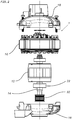
- a BPM motor 1 is substantially composed of: a stator 10; in which a rotor 12 is inserted, provided with a shaft 14 that penetrates it axially; a first shield 16, mounted on one end of the shaft 14; and a second shield 18, mounted on the opposite end of the shaft 14.
- Fig. 2 shows the motor (1) in exploded view in the assembly stage, arranged with the axis of rotation in the vertical direction and with the shields open, i.e. apart from each other.
- the stator 10 is made up of a stack of magnetic laminations, and is equipped with windings (not shown) that generate the variable magnetic field.
- the rotor 12 is supported by the shaft 14 by means of a first bearing 20 and a second bearing 22, housed in their respective shields 16 and 18.
- the shield 16 is provided centrally with a ring 24 provided with an axial opening through which one end of the shaft 14 passes.
- the shield 18 is provided with a ring 26 provided with an axial opening through which the other end of the shaft 14 passes.
- the ring 24 extends inside the shield 16 to form a seat 28 in which the first bearing 20 is housed.
- the machining accuracy of the inner surface of the seat 28 of the bearing 20 is sufficient to ensure the correct axial alignment between the shield 16 and the axis of the rotor 12.
- the ring 26 extends inside the shield 18 to form a seat 30 in which the second bearing 22 is housed.
- the shaft 14, when the motor 1 is assembled, extends outside the shield 18 to support a pulley 32, on which a belt (not shown) runs that transmits the rotation to the drum of the washing machine (not shown) for which the motor is used according to the invention.
- the essential characteristic of the present invention is represented in that an outer cylindrical surface 40 of the seat 30 of the bearing 22 housed in the shield 18, at the end of the shaft 14 that supports the pulley, is subjected to precision machining, such as turning, milling or the like, in order to be able to carry out the function of centering the components of the motor.
- This machining is particularly advantageous when it is carried out simultaneously with the machining of the inner surface of the seat 30 of the bearing 20. In effect, performing these processes simultaneously ensures the concentricity of the outer cylindrical surface 40 with the seat 30 of the bearing.
- Fig. 3 is a perspective view from the inside of the shield 18 of the motor 1 according to the invention.
- the shield 18 has a preferably square shape and it is recalled that, normally, the inner surface of the seat 30 of the bearing 22 is bored with a preferably circular section.
- the square shape of shield 18 allows one to obtain at the four corners of the shield the same number of support and closure surfaces S of the stator.
- Fig. 4 is a perspective view from the outside of the shield 18 of the motor according to the invention.
- the shield 18 has a preferably square shape and is substantially analogous to the shield 16.
- the shield 18 is provided with a ring 26, formed by an axial opening, through which one end of the shaft 14 passes.
- the cylindrical outer surface 40 of the ring 26, which projects out of the shield 18, is subjected to precision machining, such as turning, milling or the like.
- This surface 40 is easily accessible and workable with common machine tools, without requiring tools or work cycles significantly different from the traditional ones.
- this surface does not require any significant changes in the design of the rough shield and in the manufacture of the die-casting molds.
- the bearing zone is one of the few "invariants" available, being the same for all motor configurations.
- the manufacturing process of the electric motor 1 comprises the steps of: assembling the stator 10 assembly consisting of a stack of magnetic laminations and provided with windings that generate a magnetic field; assembling the rotor 12 assembly in which the driving shaft 14 is inserted and which rotates axially inside the stator and the bearings 20 and 22; inserting vertically the first and the second shield 16, 18, obtained by die-casting in aluminum, in the respective bearings opposite to the two ends of the driving shaft, so as to enclose between them the stator assembly 10 and the rotor assembly 12; aligning and centering of the rotor axis with the stator axis by means of a device with self-centering jaws (known per se and not shown).
- At least one of the first shield and the second shield 16, 18 is mechanically machined first, by milling, turning or the like, on at least one outer surface 40 thereof to create a precise reference area so as to allow the same shield to be centered with reference to at least one of the geometric axes thereof.
- said previously machined outer surface 40 of said one of the first and second shield is the cylindrical outer surface of the bearing seat, projecting axially out of the shield.
- said previously machined surface may be the surface 41 of the molding impression on the outer surface of the shield.
- the prior machining of the outer reference surface is carried out simultaneously with the boring of the bearing seat in the respective shield.
Landscapes
- Engineering & Computer Science (AREA)
- Power Engineering (AREA)
- Manufacturing & Machinery (AREA)
- Motor Or Generator Frames (AREA)
- Iron Core Of Rotating Electric Machines (AREA)
- Detergent Compositions (AREA)
Applications Claiming Priority (1)
| Application Number | Priority Date | Filing Date | Title |
|---|---|---|---|
| IT102018000010733A IT201800010733A1 (it) | 2018-11-30 | 2018-11-30 | Motore elettrico perfezionato per macchine lavabiancheria |
Publications (1)
| Publication Number | Publication Date |
|---|---|
| EP3661031A1 true EP3661031A1 (fr) | 2020-06-03 |
Family
ID=65685880
Family Applications (1)
| Application Number | Title | Priority Date | Filing Date |
|---|---|---|---|
| EP19209588.3A Pending EP3661031A1 (fr) | 2018-11-30 | 2019-11-15 | Moteur électrique amélioré pour machines à laver |
Country Status (3)
| Country | Link |
|---|---|
| EP (1) | EP3661031A1 (fr) |
| CN (1) | CN111262372A (fr) |
| IT (1) | IT201800010733A1 (fr) |
Citations (4)
| Publication number | Priority date | Publication date | Assignee | Title |
|---|---|---|---|---|
| JPS642577U (fr) * | 1987-06-24 | 1989-01-09 | ||
| FR2639160A1 (fr) * | 1988-11-15 | 1990-05-18 | Crouzet Sa | Dispositif d'ajustage de jeu axial pour moteur electrique |
| DE69738100T2 (de) * | 1996-10-03 | 2008-05-29 | General Electric Co. | Dynamoelektrische Maschine und Herstellungsverfahren derselben |
| DE102012100776A1 (de) * | 2012-01-31 | 2013-08-01 | Valeo Systèmes d'Essuyage | Scheibenwischermotor |
Family Cites Families (2)
| Publication number | Priority date | Publication date | Assignee | Title |
|---|---|---|---|---|
| JPS60144123A (ja) * | 1983-12-29 | 1985-07-30 | Fanuc Ltd | 交流サ−ボモ−タ及びその製造方法 |
| CN206595811U (zh) * | 2017-03-23 | 2017-10-27 | 广东威灵电机制造有限公司 | 用于电机的端盖和具有其的电机 |
-
2018
- 2018-11-30 IT IT102018000010733A patent/IT201800010733A1/it unknown
-
2019
- 2019-11-08 CN CN201911085992.1A patent/CN111262372A/zh active Pending
- 2019-11-15 EP EP19209588.3A patent/EP3661031A1/fr active Pending
Patent Citations (4)
| Publication number | Priority date | Publication date | Assignee | Title |
|---|---|---|---|---|
| JPS642577U (fr) * | 1987-06-24 | 1989-01-09 | ||
| FR2639160A1 (fr) * | 1988-11-15 | 1990-05-18 | Crouzet Sa | Dispositif d'ajustage de jeu axial pour moteur electrique |
| DE69738100T2 (de) * | 1996-10-03 | 2008-05-29 | General Electric Co. | Dynamoelektrische Maschine und Herstellungsverfahren derselben |
| DE102012100776A1 (de) * | 2012-01-31 | 2013-08-01 | Valeo Systèmes d'Essuyage | Scheibenwischermotor |
Also Published As
| Publication number | Publication date |
|---|---|
| IT201800010733A1 (it) | 2020-05-30 |
| CN111262372A (zh) | 2020-06-09 |
Similar Documents
| Publication | Publication Date | Title |
|---|---|---|
| EP0341317A1 (fr) | Structure de rotor pour moteur a induction a grande vitesse | |
| US10355546B2 (en) | Spindle structure, electric motor, and machine tool formed with through hole for passage of fluid | |
| US4796352A (en) | AC servomotor and a method of manufacturing the same | |
| CN103929011A (zh) | 动力工具的电机 | |
| US3320660A (en) | Methods for assembling end shield members in dynamoelectric machines | |
| US4859889A (en) | Dynamoelectric machine | |
| WO2020238265A1 (fr) | Moteur électrique et procédé d'assemblage pour moteur électrique | |
| US20190296603A1 (en) | End shield for a brushless electric motor | |
| WO2011162946A1 (fr) | Flasque de moteur ajusté à serrage | |
| CN102629798B (zh) | 旋转装置 | |
| US5894653A (en) | Method of machining motor frame body and motor machined by the method | |
| US20220045561A1 (en) | Rotor of rotary electric machine | |
| JP2021061646A (ja) | ロータ組み立て治具およびそれを用いたロータの組み立て方法 | |
| US4125791A (en) | Stator for an electrical machine | |
| EP3661031A1 (fr) | Moteur électrique amélioré pour machines à laver | |
| US12040681B2 (en) | Rotary electric machine | |
| CN105827083A (zh) | 同步水冷电主轴 | |
| JP6203344B1 (ja) | モータの組み立て治具および組み立て方法 | |
| KR20220100001A (ko) | 축방향 자속 기계용의 개선된 회전자 조립체 | |
| IT201900017300A1 (it) | Struttura di motoruota perfezionata | |
| CN211958917U (zh) | 自锁结构及使用该自锁结构的电机 | |
| US4284917A (en) | Electric motor construction | |
| JP3456824B2 (ja) | 回転電機の固定子およびその鉄心の支持方法 | |
| JP7571812B2 (ja) | 回転機 | |
| JPS5836216Y2 (ja) | 固定子および回転子を有する回転電機 |
Legal Events
| Date | Code | Title | Description |
|---|---|---|---|
| PUAI | Public reference made under article 153(3) epc to a published international application that has entered the european phase |
Free format text: ORIGINAL CODE: 0009012 |
|
| STAA | Information on the status of an ep patent application or granted ep patent |
Free format text: STATUS: THE APPLICATION HAS BEEN PUBLISHED |
|
| AK | Designated contracting states |
Kind code of ref document: A1 Designated state(s): AL AT BE BG CH CY CZ DE DK EE ES FI FR GB GR HR HU IE IS IT LI LT LU LV MC MK MT NL NO PL PT RO RS SE SI SK SM TR |
|
| AX | Request for extension of the european patent |
Extension state: BA ME |
|
| STAA | Information on the status of an ep patent application or granted ep patent |
Free format text: STATUS: REQUEST FOR EXAMINATION WAS MADE |
|
| 17P | Request for examination filed |
Effective date: 20201118 |
|
| RBV | Designated contracting states (corrected) |
Designated state(s): AL AT BE BG CH CY CZ DE DK EE ES FI FR GB GR HR HU IE IS IT LI LT LU LV MC MK MT NL NO PL PT RO RS SE SI SK SM TR |
|
| STAA | Information on the status of an ep patent application or granted ep patent |
Free format text: STATUS: EXAMINATION IS IN PROGRESS |
|
| 17Q | First examination report despatched |
Effective date: 20210531 |
|
| P01 | Opt-out of the competence of the unified patent court (upc) registered |
Effective date: 20230329 |
|
| RAP3 | Party data changed (applicant data changed or rights of an application transferred) |
Owner name: NIDEC GLOBAL APPLIANCE EUROPE S.R.L. |
|
| GRAP | Despatch of communication of intention to grant a patent |
Free format text: ORIGINAL CODE: EPIDOSNIGR1 |
|
| STAA | Information on the status of an ep patent application or granted ep patent |
Free format text: STATUS: GRANT OF PATENT IS INTENDED |
|
| INTG | Intention to grant announced |
Effective date: 20260122 |