EP3661044A1 - Genset - Google Patents
Genset Download PDFInfo
- Publication number
- EP3661044A1 EP3661044A1 EP19211649.9A EP19211649A EP3661044A1 EP 3661044 A1 EP3661044 A1 EP 3661044A1 EP 19211649 A EP19211649 A EP 19211649A EP 3661044 A1 EP3661044 A1 EP 3661044A1
- Authority
- EP
- European Patent Office
- Prior art keywords
- variable speed
- generator set
- control module
- module
- set according
- Prior art date
- Legal status (The legal status is an assumption and is not a legal conclusion. Google has not performed a legal analysis and makes no representation as to the accuracy of the status listed.)
- Withdrawn
Links
- 239000000446 fuel Substances 0.000 claims abstract description 6
- 238000004146 energy storage Methods 0.000 claims description 12
- 238000002485 combustion reaction Methods 0.000 claims description 10
- 238000001816 cooling Methods 0.000 claims description 10
- 239000002184 metal Substances 0.000 claims description 6
- 238000009423 ventilation Methods 0.000 claims description 6
- 230000007935 neutral effect Effects 0.000 claims description 4
- 239000004020 conductor Substances 0.000 claims description 3
- 229910001416 lithium ion Inorganic materials 0.000 claims description 3
- 239000007789 gas Substances 0.000 description 4
- 238000010586 diagram Methods 0.000 description 2
- 238000005265 energy consumption Methods 0.000 description 1
- 238000005516 engineering process Methods 0.000 description 1
- 230000005284 excitation Effects 0.000 description 1
- 239000002803 fossil fuel Substances 0.000 description 1
- 239000005431 greenhouse gas Substances 0.000 description 1
- 230000002028 premature Effects 0.000 description 1
- 230000001360 synchronised effect Effects 0.000 description 1
- 238000004804 winding Methods 0.000 description 1
Images


Classifications
-
- H—ELECTRICITY
- H02—GENERATION; CONVERSION OR DISTRIBUTION OF ELECTRIC POWER
- H02P—CONTROL OR REGULATION OF ELECTRIC MOTORS, ELECTRIC GENERATORS OR DYNAMO-ELECTRIC CONVERTERS; CONTROLLING TRANSFORMERS, REACTORS OR CHOKE COILS
- H02P9/00—Arrangements for controlling electric generators for the purpose of obtaining a desired output
- H02P9/48—Arrangements for obtaining a constant output value at varying speed of the generator, e.g. on vehicle
-
- F—MECHANICAL ENGINEERING; LIGHTING; HEATING; WEAPONS; BLASTING
- F01—MACHINES OR ENGINES IN GENERAL; ENGINE PLANTS IN GENERAL; STEAM ENGINES
- F01P—COOLING OF MACHINES OR ENGINES IN GENERAL; COOLING OF INTERNAL-COMBUSTION ENGINES
- F01P11/00—Component parts, details, or accessories not provided for in, or of interest apart from, groups F01P1/00 - F01P9/00
- F01P11/10—Guiding or ducting cooling-air, to, or from, liquid-to-air heat exchangers
-
- F—MECHANICAL ENGINEERING; LIGHTING; HEATING; WEAPONS; BLASTING
- F01—MACHINES OR ENGINES IN GENERAL; ENGINE PLANTS IN GENERAL; STEAM ENGINES
- F01P—COOLING OF MACHINES OR ENGINES IN GENERAL; COOLING OF INTERNAL-COMBUSTION ENGINES
- F01P3/00—Liquid cooling
- F01P3/20—Cooling circuits not specific to a single part of engine or machine
-
- F—MECHANICAL ENGINEERING; LIGHTING; HEATING; WEAPONS; BLASTING
- F01—MACHINES OR ENGINES IN GENERAL; ENGINE PLANTS IN GENERAL; STEAM ENGINES
- F01P—COOLING OF MACHINES OR ENGINES IN GENERAL; COOLING OF INTERNAL-COMBUSTION ENGINES
- F01P5/00—Pumping cooling-air or liquid coolants
- F01P5/02—Pumping cooling-air; Arrangements of cooling-air pumps, e.g. fans or blowers
- F01P5/06—Guiding or ducting air to, or from, ducted fans
-
- F—MECHANICAL ENGINEERING; LIGHTING; HEATING; WEAPONS; BLASTING
- F02—COMBUSTION ENGINES; HOT-GAS OR COMBUSTION-PRODUCT ENGINE PLANTS
- F02B—INTERNAL-COMBUSTION PISTON ENGINES; COMBUSTION ENGINES IN GENERAL
- F02B63/00—Adaptations of engines for driving pumps, hand-held tools or electric generators; Portable combinations of engines with engine-driven devices
- F02B63/04—Adaptations of engines for driving pumps, hand-held tools or electric generators; Portable combinations of engines with engine-driven devices for electric generators
- F02B63/044—Adaptations of engines for driving pumps, hand-held tools or electric generators; Portable combinations of engines with engine-driven devices for electric generators the engine-generator unit being placed on a frame or in an housing
-
- H—ELECTRICITY
- H02—GENERATION; CONVERSION OR DISTRIBUTION OF ELECTRIC POWER
- H02P—CONTROL OR REGULATION OF ELECTRIC MOTORS, ELECTRIC GENERATORS OR DYNAMO-ELECTRIC CONVERTERS; CONTROLLING TRANSFORMERS, REACTORS OR CHOKE COILS
- H02P9/00—Arrangements for controlling electric generators for the purpose of obtaining a desired output
- H02P9/10—Control effected upon generator excitation circuit to reduce harmful effects of overloads or transients, e.g. sudden application of load, sudden removal of load, sudden change of load
Definitions
- the present description relates, as its title indicates, to a generator set that has an electronic converter to supply electrical energy and in which the heat engine rotates at variable speed, depending on the power demanded by the load.
- the invention relates to the field of generator sets, specifically variable speed generator sets.
- This type of device includes an electric generator or alternator, which is attached to a heat engine of different types - diesel, petrol, gas or any other -, and at its output, generates alternating current electrical energy at a voltage, defined by the alternator winding, and frequency, defined by the speed at which the combustion engine rotates.
- a heat engine of different types - diesel, petrol, gas or any other -, and at its output, generates alternating current electrical energy at a voltage, defined by the alternator winding, and frequency, defined by the speed at which the combustion engine rotates.
- a generator set capable of supplying electrical energy at a fixed frequency and voltage has been devised, using a combustion heat engine rotating at variable speed.
- the generator set comprises a heat engine powered by different fuels, - for example diesel, petrol or gas, - which rotates at different speeds depending on the type of engine used.
- This heat engine is attached to an electric machine, which may be an alternator or any other type of electric machine, such as a permanent magnet alternator, a reluctance machine, or any other type of generator that creates different voltage and frequency depending on the speed at which the combustion engine rotates.
- the electrical output of the electric machine is connected to a converter module that is responsible for providing alternating current voltage to the output connectors, for the load.
- This converter module transforms the voltage and variable frequency into direct current voltage by means of a DC/AC inverter module.
- the next step is an inverting stage that uses that DC voltage to produce an AC voltage of an amplitude and frequency fixed by the converter configuration.
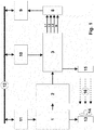
- variable speed generator set can be seen to comprise:
- the three control modules (9, 10, 11) are interconnected to each other by means of a digital communications bus (12), which shall preferably be of the CANbus type.
- Figure 2 shows that the electronic converter module (3) comprises
- the energy storage devices (7) can be chosen from any group formed by Li-Ion batteries, lead batteries and supercapacitors, and may be a combination thereof.
- This energy storage device (7) provides the DC bus before the DC/AC inverter module (5) with additional capacity to supply current, so that it reacts more quickly to rapid variations or surges of the load associated with the output connectors for the load (8), using the stored energy, while the heat engine (1) is requested to increase speed to supply power to the load.
- the heat engine (1) is a combustion type engine and its fuel is chosen from the group formed by diesel, petrol or gas.
- This heat engine (1) comprises a radiator (13) associated with a forced ventilation device (14), which creates a flow of cooling air (16), while the electronic converter module (3) also has a radiator (15) for heat evacuation, inserted at the input of the course of the cooling air flow (16), providing better cooling of the electronic circuits using a passive radiator (13) without any need for additional forced ventilation.
- the electric machine (2) generating energy may be a permanent magnet alternator or a reluctance machine, or any other type of generator that creates a different voltage and frequency depending on the rotation speed of the heat engine (1).
- the electrical energy at the output connectors for the load (8) is preferably in the form of three-phase voltage, with three conductors L1, L2 and L3 plus neutral N.
- the metal chassis (17) shall be provided with wheels, openings for a pallet-jack or hooks for transportation and lifting, or a combination of thereof.
- variable speed generator set presented here affords multiple advantages over currently available equipment, the most important being that it allows for a reduction of up to approximately 60% in fuel consumption compared to a traditional generator with the same power rating, with the consequent savings in operating costs.
- Another advantage of the present invention is that, due to the electronic output stage, its capacity to provide current is approximately 4 times greater than a traditional generator of its power rating, thus enabling it to replace generators of a greater volume, weight and economic cost.
- variable speed technology in the combustion engine is that it works at its optimal regime for any power delivery, which optimises its service life, thus improving its cost performance and reducing its wear and tear.
- the electronic circuit radiator is located at the input of the course of the cooling air flow of the heat engine, it provides better cooling of the electronic circuits using a passive radiator, without any need for additional forced ventilation for them. This results in greater reliability and durability of the electronic parts and a lower number of failures.
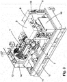
- variable speed generator set To gain a better understanding of the object of this invention, a preferred practical embodiment of a variable speed generator set has been depicted in the attached drawing.
- variable speed generator set can be seen to comprise
- the generator control modules (9), the converter module control module (10) and the engine control module (11) are interconnected to each other by means of a digital communications bus (12), which shall preferably be of the CANbus type.
- Figure 2 shows that the electronic converter module (3) comprises
- the energy storage devices (7) are chosen from the group formed by Li-Ion batteries, lead batteries and supercapacitors, and may be a combination thereof.
- This energy storage device (7) provides the DC bus before the DC/AC inverter module (5) with additional capacity to supply current, so that it reacts more quickly to rapid variations or surges of the load associated with the output connectors for the load (8), using the energy stored, while the heat engine (1) is requested to increase speed to supply power to the load.
- the heat engine (1) is a combustion-type engine and its fuel is chosen from the group formed by diesel, petrol or gas.
- This heat engine (1) comprises a radiator (13) associated with a forced ventilation device (14), which creates a flow of cooling air (16), while the electronic converter module (3) also has a radiator (15) for heat evacuation inserted at the input of the course of the cooling air flow (16), providing better cooling of the electronic circuits using a passive radiator (13) without any need for additional forced ventilation.
- the electric machine (2) generating energy may be a permanent magnet alternator or a reluctance machine, or any other type of generator that creates a different voltage and frequency depending on the rotation speed of the heat engine (1).
- the electrical energy at the output connectors for the load (8) is preferably in the form of three-phase voltage, with three conductors L1, L2 and L3 plus neutral N.
- the metal chassis (17) shall be provided with wheels, openings for a pallet-jack or hooks for its transportation or lifting, or a combination thereof.
Landscapes
- Engineering & Computer Science (AREA)
- Chemical & Material Sciences (AREA)
- Combustion & Propulsion (AREA)
- Mechanical Engineering (AREA)
- General Engineering & Computer Science (AREA)
- Power Engineering (AREA)
- Control Of Eletrric Generators (AREA)
Applications Claiming Priority (1)
| Application Number | Priority Date | Filing Date | Title |
|---|---|---|---|
| ES201831856U ES1225959Y (es) | 2018-11-29 | 2018-11-29 | Grupo electrogeno de velocidad variable |
Publications (1)
| Publication Number | Publication Date |
|---|---|
| EP3661044A1 true EP3661044A1 (de) | 2020-06-03 |
Family
ID=65581054
Family Applications (1)
| Application Number | Title | Priority Date | Filing Date |
|---|---|---|---|
| EP19211649.9A Withdrawn EP3661044A1 (de) | 2018-11-29 | 2019-11-26 | Genset |
Country Status (2)
| Country | Link |
|---|---|
| EP (1) | EP3661044A1 (de) |
| ES (1) | ES1225959Y (de) |
Citations (9)
| Publication number | Priority date | Publication date | Assignee | Title |
|---|---|---|---|---|
| ES2225715T3 (es) | 2001-11-17 | 2005-03-16 | Semikron Elektronik Gmbh | Conjunto de circuitos. |
| US20070227470A1 (en) * | 2003-08-28 | 2007-10-04 | Mainstream Engineering Corporation | Lightweight Portable Electric Generator with Integrated Starter/Alternator |
| EP1881177A1 (de) * | 2006-07-21 | 2008-01-23 | C.R.F. Società Consortile per Azioni | Modulares Energieerzeugungssystem |
| CN101162885A (zh) | 2007-11-14 | 2008-04-16 | 深圳市京能纺系统集成有限公司 | 变速柴油发电机 |
| US20090045761A1 (en) | 2006-03-07 | 2009-02-19 | Siemens Aktiengesellschaft | Diesel-electric drive system having a synchronous generator with permanent-magnet excitation |
| US20090072772A1 (en) | 2006-03-07 | 2009-03-19 | Siemens Aktiengesellschaft | Diesel-electric drive system having a synchronous generator with permanent magnet excitation |
| CH701753A1 (de) | 2009-09-03 | 2011-03-15 | Ids Holding Ag | Generatorsystem mit direkt netzgekoppeltem Generator und Verfahren zum Durchfahren von Netzstörungen. |
| ES2459940T3 (es) | 2010-04-29 | 2014-05-13 | Ingeteam Power Technology, S.A. | Sistema y procedimiento de control de un generador eléctrico |
| GB2527805A (en) * | 2014-07-02 | 2016-01-06 | Bamford Excavators Ltd | A generator set |
-
2018
- 2018-11-29 ES ES201831856U patent/ES1225959Y/es not_active Expired - Fee Related
-
2019
- 2019-11-26 EP EP19211649.9A patent/EP3661044A1/de not_active Withdrawn
Patent Citations (9)
| Publication number | Priority date | Publication date | Assignee | Title |
|---|---|---|---|---|
| ES2225715T3 (es) | 2001-11-17 | 2005-03-16 | Semikron Elektronik Gmbh | Conjunto de circuitos. |
| US20070227470A1 (en) * | 2003-08-28 | 2007-10-04 | Mainstream Engineering Corporation | Lightweight Portable Electric Generator with Integrated Starter/Alternator |
| US20090045761A1 (en) | 2006-03-07 | 2009-02-19 | Siemens Aktiengesellschaft | Diesel-electric drive system having a synchronous generator with permanent-magnet excitation |
| US20090072772A1 (en) | 2006-03-07 | 2009-03-19 | Siemens Aktiengesellschaft | Diesel-electric drive system having a synchronous generator with permanent magnet excitation |
| EP1881177A1 (de) * | 2006-07-21 | 2008-01-23 | C.R.F. Società Consortile per Azioni | Modulares Energieerzeugungssystem |
| CN101162885A (zh) | 2007-11-14 | 2008-04-16 | 深圳市京能纺系统集成有限公司 | 变速柴油发电机 |
| CH701753A1 (de) | 2009-09-03 | 2011-03-15 | Ids Holding Ag | Generatorsystem mit direkt netzgekoppeltem Generator und Verfahren zum Durchfahren von Netzstörungen. |
| ES2459940T3 (es) | 2010-04-29 | 2014-05-13 | Ingeteam Power Technology, S.A. | Sistema y procedimiento de control de un generador eléctrico |
| GB2527805A (en) * | 2014-07-02 | 2016-01-06 | Bamford Excavators Ltd | A generator set |
Also Published As
| Publication number | Publication date |
|---|---|
| ES1225959Y (es) | 2019-05-28 |
| ES1225959U (es) | 2019-03-06 |
Similar Documents
| Publication | Publication Date | Title |
|---|---|---|
| US8022572B2 (en) | Genset system with energy storage for transient response | |
| CN105576921B (zh) | 可动态重构的电机、电机系统及电机动态重构方法 | |
| US20150349687A1 (en) | Electric Power Generation and Distribution for Islanded or Weakly-Connected Systems | |
| US20090218970A1 (en) | Starting and Generating Multiplying Cotnrol System,and Method for Using the System, and an Electromotion Mixed Dynamic Vehicle | |
| US20100085787A1 (en) | System and method for powering a hybrid electric vehicle | |
| JP6824383B2 (ja) | 回転電機システム | |
| US12027940B2 (en) | Rectifier | |
| US20100207590A1 (en) | High frequency generator without rotating diode rectifier | |
| US20150275750A1 (en) | Mixed Fuel Electric Power System | |
| EP2719888A1 (de) | Startergenerator für einen Dualer-Gleichstrom-Bus | |
| CN101399459A (zh) | 一种用于永磁发电机的可控调压方法及其装置 | |
| EP3065260A1 (de) | Bodenstromaggregat mit geringer Lärm- und Schadstoffemission | |
| Mese et al. | Investigating operating modes and converter options of dual winding permanent magnet synchronous machines for hybrid electric vehicles | |
| Bram et al. | Variable speed genset with full rated power converter using readily available industrial products | |
| US7710058B2 (en) | Motor drive architecture for high frequency AC bus | |
| EP3661044A1 (de) | Genset | |
| CN105207334A (zh) | 用于向负载供应电力的系统以及对应电力供应方法 | |
| Aizza et al. | Coordinated speed and voltage regulation of a DC power generation system based on a woundfield split-phase generator supplying multiple rectifiers | |
| Chakraborty et al. | A new series of brushless and permanent magnetless synchronous machines | |
| CN207559825U (zh) | 基于异步电机自励磁的船舶直流组网电力推进系统 | |
| Fukao et al. | Voltage control of super high-speed reluctance generator system with a PWM voltage source converter | |
| RU150254U1 (ru) | Устройство электропитания постоянным током автономного транспортного судна | |
| CN103190059A (zh) | 具有集成逆变器的电机 | |
| US11128139B2 (en) | Power electronics conditioning system with half-winding generator setup | |
| RU2419957C1 (ru) | Электроэнергетическая установка |
Legal Events
| Date | Code | Title | Description |
|---|---|---|---|
| PUAI | Public reference made under article 153(3) epc to a published international application that has entered the european phase |
Free format text: ORIGINAL CODE: 0009012 |
|
| STAA | Information on the status of an ep patent application or granted ep patent |
Free format text: STATUS: THE APPLICATION HAS BEEN PUBLISHED |
|
| AK | Designated contracting states |
Kind code of ref document: A1 Designated state(s): AL AT BE BG CH CY CZ DE DK EE ES FI FR GB GR HR HU IE IS IT LI LT LU LV MC MK MT NL NO PL PT RO RS SE SI SK SM TR |
|
| AX | Request for extension of the european patent |
Extension state: BA ME |
|
| STAA | Information on the status of an ep patent application or granted ep patent |
Free format text: STATUS: REQUEST FOR EXAMINATION WAS MADE |
|
| 17P | Request for examination filed |
Effective date: 20201202 |
|
| RBV | Designated contracting states (corrected) |
Designated state(s): AL AT BE BG CH CY CZ DE DK EE ES FI FR GB GR HR HU IE IS IT LI LT LU LV MC MK MT NL NO PL PT RO RS SE SI SK SM TR |
|
| STAA | Information on the status of an ep patent application or granted ep patent |
Free format text: STATUS: EXAMINATION IS IN PROGRESS |
|
| 17Q | First examination report despatched |
Effective date: 20211112 |
|
| P01 | Opt-out of the competence of the unified patent court (upc) registered |
Effective date: 20230529 |
|
| STAA | Information on the status of an ep patent application or granted ep patent |
Free format text: STATUS: THE APPLICATION IS DEEMED TO BE WITHDRAWN |
|
| 18D | Application deemed to be withdrawn |
Effective date: 20240103 |