EP3661088B1 - Hybrides automatisches wiederholungsanforderungsergebnisrückkopplungsverfahren und vorrichtung - Google Patents
Hybrides automatisches wiederholungsanforderungsergebnisrückkopplungsverfahren und vorrichtung Download PDFInfo
- Publication number
- EP3661088B1 EP3661088B1 EP17918788.5A EP17918788A EP3661088B1 EP 3661088 B1 EP3661088 B1 EP 3661088B1 EP 17918788 A EP17918788 A EP 17918788A EP 3661088 B1 EP3661088 B1 EP 3661088B1
- Authority
- EP
- European Patent Office
- Prior art keywords
- uplink carrier
- target
- downlink
- group
- carrier group
- Prior art date
- Legal status (The legal status is an assumption and is not a legal conclusion. Google has not performed a legal analysis and makes no representation as to the accuracy of the status listed.)
- Active
Links
Images




Classifications
-
- H—ELECTRICITY
- H04—ELECTRIC COMMUNICATION TECHNIQUE
- H04L—TRANSMISSION OF DIGITAL INFORMATION, e.g. TELEGRAPHIC COMMUNICATION
- H04L1/00—Arrangements for detecting or preventing errors in the information received
- H04L1/12—Arrangements for detecting or preventing errors in the information received by using return channel
- H04L1/16—Arrangements for detecting or preventing errors in the information received by using return channel in which the return channel carries supervisory signals, e.g. repetition request signals
- H04L1/18—Automatic repetition systems, e.g. Van Duuren systems
- H04L1/1806—Go-back-N protocols
-
- H—ELECTRICITY
- H04—ELECTRIC COMMUNICATION TECHNIQUE
- H04L—TRANSMISSION OF DIGITAL INFORMATION, e.g. TELEGRAPHIC COMMUNICATION
- H04L1/00—Arrangements for detecting or preventing errors in the information received
- H04L1/12—Arrangements for detecting or preventing errors in the information received by using return channel
- H04L1/16—Arrangements for detecting or preventing errors in the information received by using return channel in which the return channel carries supervisory signals, e.g. repetition request signals
- H04L1/18—Automatic repetition systems, e.g. Van Duuren systems
- H04L1/1812—Hybrid protocols; Hybrid automatic repeat request [HARQ]
-
- H—ELECTRICITY
- H04—ELECTRIC COMMUNICATION TECHNIQUE
- H04L—TRANSMISSION OF DIGITAL INFORMATION, e.g. TELEGRAPHIC COMMUNICATION
- H04L1/00—Arrangements for detecting or preventing errors in the information received
- H04L1/12—Arrangements for detecting or preventing errors in the information received by using return channel
- H04L1/16—Arrangements for detecting or preventing errors in the information received by using return channel in which the return channel carries supervisory signals, e.g. repetition request signals
- H04L1/1607—Details of the supervisory signal
- H04L1/1628—List acknowledgements, i.e. the acknowledgement message consisting of a list of identifiers, e.g. of sequence numbers
-
- H—ELECTRICITY
- H04—ELECTRIC COMMUNICATION TECHNIQUE
- H04L—TRANSMISSION OF DIGITAL INFORMATION, e.g. TELEGRAPHIC COMMUNICATION
- H04L1/00—Arrangements for detecting or preventing errors in the information received
- H04L1/004—Arrangements for detecting or preventing errors in the information received by using forward error control
- H04L1/0056—Systems characterized by the type of code used
- H04L1/0061—Error detection codes
-
- H—ELECTRICITY
- H04—ELECTRIC COMMUNICATION TECHNIQUE
- H04L—TRANSMISSION OF DIGITAL INFORMATION, e.g. TELEGRAPHIC COMMUNICATION
- H04L1/00—Arrangements for detecting or preventing errors in the information received
- H04L1/12—Arrangements for detecting or preventing errors in the information received by using return channel
- H04L1/16—Arrangements for detecting or preventing errors in the information received by using return channel in which the return channel carries supervisory signals, e.g. repetition request signals
- H04L1/18—Automatic repetition systems, e.g. Van Duuren systems
- H04L1/1829—Arrangements specially adapted for the receiver end
- H04L1/1854—Scheduling and prioritising arrangements
-
- H—ELECTRICITY
- H04—ELECTRIC COMMUNICATION TECHNIQUE
- H04L—TRANSMISSION OF DIGITAL INFORMATION, e.g. TELEGRAPHIC COMMUNICATION
- H04L5/00—Arrangements affording multiple use of the transmission path
- H04L5/0001—Arrangements for dividing the transmission path
- H04L5/0003—Two-dimensional division
- H04L5/0005—Time-frequency
- H04L5/0007—Time-frequency the frequencies being orthogonal, e.g. OFDM(A) or DMT
- H04L5/0008—Wavelet-division
-
- H—ELECTRICITY
- H04—ELECTRIC COMMUNICATION TECHNIQUE
- H04L—TRANSMISSION OF DIGITAL INFORMATION, e.g. TELEGRAPHIC COMMUNICATION
- H04L5/00—Arrangements affording multiple use of the transmission path
- H04L5/0001—Arrangements for dividing the transmission path
- H04L5/0003—Two-dimensional division
- H04L5/0005—Time-frequency
- H04L5/0007—Time-frequency the frequencies being orthogonal, e.g. OFDM(A) or DMT
- H04L5/001—Time-frequency the frequencies being orthogonal, e.g. OFDM(A) or DMT the frequencies being arranged in component carriers
-
- H—ELECTRICITY
- H04—ELECTRIC COMMUNICATION TECHNIQUE
- H04L—TRANSMISSION OF DIGITAL INFORMATION, e.g. TELEGRAPHIC COMMUNICATION
- H04L5/00—Arrangements affording multiple use of the transmission path
- H04L5/003—Arrangements for allocating sub-channels of the transmission path
- H04L5/0053—Allocation of signalling, i.e. of overhead other than pilot signals
- H04L5/0055—Physical resource allocation for ACK/NACK
-
- H—ELECTRICITY
- H04—ELECTRIC COMMUNICATION TECHNIQUE
- H04L—TRANSMISSION OF DIGITAL INFORMATION, e.g. TELEGRAPHIC COMMUNICATION
- H04L5/00—Arrangements affording multiple use of the transmission path
- H04L5/0091—Signalling for the administration of the divided path, e.g. signalling of configuration information
-
- H—ELECTRICITY
- H04—ELECTRIC COMMUNICATION TECHNIQUE
- H04W—WIRELESS COMMUNICATION NETWORKS
- H04W72/00—Local resource management
- H04W72/04—Wireless resource allocation
-
- H—ELECTRICITY
- H04—ELECTRIC COMMUNICATION TECHNIQUE
- H04W—WIRELESS COMMUNICATION NETWORKS
- H04W72/00—Local resource management
- H04W72/20—Control channels or signalling for resource management
- H04W72/21—Control channels or signalling for resource management in the uplink direction of a wireless link, i.e. towards the network
-
- H—ELECTRICITY
- H04—ELECTRIC COMMUNICATION TECHNIQUE
- H04W—WIRELESS COMMUNICATION NETWORKS
- H04W74/00—Wireless channel access
- H04W74/08—Non-scheduled access, e.g. ALOHA
- H04W74/0808—Non-scheduled access, e.g. ALOHA using carrier sensing, e.g. carrier sense multiple access [CSMA]
-
- H—ELECTRICITY
- H04—ELECTRIC COMMUNICATION TECHNIQUE
- H04W—WIRELESS COMMUNICATION NETWORKS
- H04W76/00—Connection management
- H04W76/20—Manipulation of established connections
- H04W76/27—Transitions between radio resource control [RRC] states
-
- H—ELECTRICITY
- H04—ELECTRIC COMMUNICATION TECHNIQUE
- H04W—WIRELESS COMMUNICATION NETWORKS
- H04W80/00—Wireless network protocols or protocol adaptations to wireless operation
- H04W80/02—Data link layer protocols
Definitions
- the present disclosure generally relates to the technical field of communications, and more particularly, to methods, devices and a computer-readable storage medium for feeding back a Hybrid Automatic Repeat reQuest (HARQ) result.
- HARQ Hybrid Automatic Repeat reQuest
- a feedback about a downlink HARQ result is a feedback from a terminal to a Physical Downlink Shared Channel (PDSCH) and is for notifying a base station whether the PDSCH is successfully decoded or not.
- PDSCH Physical Downlink Shared Channel
- a Physical Uplink Control Channel can only be transmitted in a master cell corresponding to a terminal, and thus a terminal can transmit only one PUCCH in one subframe. This means that HARQ results associated with downlink data sent by multiple downlink component carriers are required to be sent on the same uplink component carrier.
- a terminal may add a Cyclic Redundancy Check (CRC) bit to a new PUCCH format before channel coding is implemented, and CRC may be performed on received PUCCH information on a base station side.
- CRC Cyclic Redundancy Check
- a channel situation change may cause an information transmission error of a PUCCH to further cause a PUCCH CRC failure, and in such case, a base station cannot receive a HARQ result fed back by a terminal on the PUCCH and data on all carriers related to feedback information is required to be retransmitted. Consequently, transmission resources are greatly wasted, and system performance is degraded.
- LAA License Assisted Access
- 3GPP 3rd Generation Partnership Project
- LAA is one of key technologies for solving a problem about LTE network expansion by use of an unauthorized spectrum.
- Enhanced LAA eLAA
- 3GPP Release 14 3rd Generation Partnership Project
- LBT Listen Before Talk
- CCA Channel Clear Assessment
- Dual Connectivity DC
- DC Dual Connectivity
- the reliability of a feedback on a HARQ result through a PUCCH in the LAA system is relatively low.
- first, second, third and the like may be adopted to describe various information in the present disclosure, the information should not be limited to these terms. These terms are only adopted to distinguish the information of the same type.
- first information may also be called second information and, similarly, second information may also be called first information.
- second information may also be called first information.
- term “if” used here may be explained as “while” or “when” or “responsive to determining”, which depends on the context.
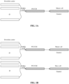
- uplink CA only supports a PUCCH in a master cell, and all PDSCHs are fed back on one PUCCH.
- a mapping manner for feeding back a HARQ result through a PUCCH is shown in FIG. 1A .
- APUCCH in a slave cell is introduced into 3GPP Release 13, and at most two PUCCHs may be supported.
- the PUCCH is only configured on a granted carrier.
- a mapping manner for feeding back a HARQ result through a PUCCH is shown in FIG. 1B .
- the embodiments of the present disclosure provide the following method and device for feeding back a HARQ result.
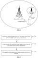
- FIG. 2 A scenario of feeding back a HARQ result provided in the embodiments of the present disclosure is shown in FIG. 2 .
- a master base station is deployed in a granted spectrum
- a slave base station is deployed in an unauthorized spectrum
- enhanced CA is implemented for the LAA system
- a terminal may support multiple PUCCHs, and each PUCCH may carry a HARQ result.
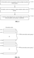
- FIG. 3 is a flowchart illustrating a method for feeding back a HARQ result according to an exemplary embodiment. The method may be applied to a base station and includes the following steps.
- Step 101 a mapping relationship between each downlink carrier group and each uplink carrier group is determined, each downlink carrier group includes at least one downlink carrier and each uplink carrier group includes at least one uplink carrier.
- Step 102 a target manner for acquiring a target uplink carrier from the each uplink carrier group is determined, the target uplink carrier is an uplink carrier configured to carry a target HARQ result in a present uplink carrier group, and the target HARQ result includes HARQ results of downlink data carried on all the downlink carriers in a downlink carrier group corresponding to the present uplink carrier group.
- Step 103 the mapping relationship and the target manner are sent to a terminal to enable the terminal to feed back the target HARQ result through the target uplink carrier after determining the target uplink carrier in the present uplink carrier group according to the target manner.
- the base station may send the mapping relationship between each downlink carrier group and each uplink carrier group and the target manner for acquiring the target uplink carrier from the each uplink carrier group to the terminal, and the terminal, after determining the target uplink carrier in the present uplink carrier group according to the target manner, feeds back the target HARQ result through the target uplink carrier;
- the target uplink carrier is an uplink carrier configured to carry the target HARQ result in the present uplink carrier group and the target HARQ result includes the HARQ results of downlink data carried on all the downlink carriers in a downlink carrier group corresponding to the present uplink carrier group.
- FIG. 4 is a flowchart illustrating another method for feeding back a HARQ result according to the embodiment shown in FIG. 3 .
- Step 101 may include the following steps.
- Step 101-1 all downlink carriers are grouped to obtain multiple downlink carrier groups.
- the base station may group all the downlink carriers, thereby obtaining the multiple downlink carrier groups.
- grouping may be performed according to the total number of the downlink carriers.
- a first situation is that: the total number of all the downlink carriers exceeds a first threshold.
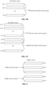
- the number of downlink component carriers is relatively large, and correspondingly, more HARQ results are needed to be fed back, which may result in that a PUCCH is overloaded. Therefore, when the downlink carriers are grouped, non-overlapping grouping may be performed on the downlink carriers. All the downlink carriers may be divided into a target number of first downlink carrier groups, any two first downlink carrier groups may include different downlink carriers and the target number may be the number of PUCCHs supported by the terminal.
- downlink carrier CC1 to downlink carrier CC16 are divided into a group, and downlink carrier CC17 to downlink carrier CC32 are divided into another group.
- a second situation is that: the total number of all the downlink carriers is less than a second threshold.
- the second threshold is less than the first threshold.
- the number of the downlink component carriers is relatively small, HARQ results corresponding to all the downlink carriers may completely be carried through a PUCCH, and then complete overlapping grouping may be performed. All the downlink carriers may be divided into a group to obtain a second downlink carrier group, and the HARQ results corresponding to all the downlink carriers may be subsequently fed back through different target uplink carriers, so that reliability of a feedback on a HARQ result can be improved.
- downlink carriers when enhanced CA is deployed in the unauthorized spectrum in the DC scenario, 5 downlink carriers are aggregated, and the terminal supports two PUCCHs. In such case, the total number of the downlink carriers is relatively small and less than the second threshold, and all the downlink carriers are divided into a group to obtain the second downlink carrier group. As shown in FIG. 5B , downlink carrier CC1 to downlink carrier CC5 are divided into the same group.
- a third situation is that: the total number of all the downlink carriers ranges from the second threshold to the first threshold.
- the total number of the downlink carriers ranges from the second threshold to the first threshold; if the HARQ results corresponding to all the downlink carriers are fed back through one PUCCH, the PUCCH may be overloaded, and if the downlink carriers are divided into multiple downlink carrier groups that are completely non-overlapping, waste may be brought. Therefore, partial overlapping grouping may be performed on all the downlink carriers to divide the downlink carrier carrying data with higher priority into different downlink carrier groups in an overlapping manner to obtain multiple third downlink carrier groups.
- the number of the third downlink carrier groups may also be the number of the PUCCHs supported by the terminal. The reliability of a feedback on a HARQ result can be improved.
- downlink component CC1 to downlink carrier CC9 may be divided into a group, and the downlink carrier CC8 to downlink carrier CC16 may be divided into another group.
- the downlink carrier CC8 and downlink carrier CC9 which have higher priority belong to both third downlink carrier group 1 and third downlink carrier group 2.
- Step 101-2 all uplink carriers are grouped to obtain multiple uplink carrier groups.
- the base station may further perform non-overlapping grouping on all the uplink carriers, and all the uplink carriers are divided into the target number of groups, the target number being the number of the PUCCHs supported by the terminal.
- uplink carrier CC1 to uplink carrier CC3 may be divided into uplink carrier group 1
- uplink carrier CC4 and uplink carrier CC5 may be divided into uplink carrier group 2.
- Step 101-3 the mapping relationship between each downlink carrier group and each uplink carrier group is established.
- the base station has divided all the downlink carriers and all the uplink carriers, and if the group number of the downlink carrier groups is the target number, a mapping relationship that each downlink carrier group corresponds to each uplink carrier group one to one may be established because the number of the uplink carrier groups is also the target number.
- the base station divides the downlink carrier CC1 to the downlink carrier CC16 into the first downlink carrier group 1 and divides the downlink carrier CC17 to the downlink carrier CC32 into the first downlink carrier group 2, and in addition, the base station divides the uplink carrier CC1 to the uplink carrier CC3 into the uplink carrier group 1 and divides the uplink carrier CC4 and the uplink carrier CC5 into the uplink carrier group 2.
- the established mapping relationship is shown in Table 1.
- Uplink carrier group Uplink carrier group First downlink carrier group 1 (downlink carrier CC1 to downlink carrier CC 16) Uplink carrier group 1 (uplink carrier CC1 to uplink carrier CC3) First downlink carrier group 2 (downlink carrier CC16 to downlink carrier CC32) Uplink carrier group 2 (uplink carrier CC4 and uplink carrier CC5)
- the group number of the downlink carrier groups is 1, a mapping relationship between the downlink carrier group and each uplink carrier group is established.
- the base station divides the downlink carrier CC1 to the downlink carrier CC5 into the same group to obtain the second downlink carrier group, and in addition, the base station divides the uplink carrier CC1 to the uplink carrier CC3 into the uplink carrier group 1 and divides the uplink carrier CC4 and the uplink carrier CC5 into the uplink carrier group 2.
- the established mapping relationship may be shown in Table 2.
- Table 2 Downlink carrier group Uplink carrier group
- Second downlink carrier group (downlink carrier CC1 to downlink carrier CC5)
- Uplink carrier group 1 uplink carrier CC1 to uplink carrier CC3
- Second downlink carrier group downlink carrier CC1 to downlink carrier CC5
- Uplink carrier group 2 uplink carrier CC4 and uplink carrier CC5
- the base station may further determine for the terminal the target manner for acquiring the target uplink carrier from the each uplink carrier group.
- the target uplink carrier may be an uplink carrier configured to carry the target HARQ result in the present uplink carrier group, and the target HARQ result may include the HARQ results of downlink data carried on all the downlink carriers in the downlink carrier group corresponding to the present uplink carrier group.
- the present uplink carrier group includes the uplink carrier CC1, the uplink carrier CC2 and the uplink carrier CC3, and the downlink carrier group corresponding to the present uplink carrier group is the first downlink carrier group 1 and includes the downlink carrier CC1 to the downlink carrier CC16.
- the target uplink carrier is one of the uplink carrier CC1, the uplink carrier CC2 and the uplink carrier CC3, and is configured to carry HARQ results of the downlink data carried on the downlink carrier CC1 to the downlink carrier CC16.
- the target manner for acquiring the target uplink carrier may include any one of that:
- the base station may specify any manner as the target manner for acquiring, by the terminal, the target uplink carrier in the uplink carrier group.
- the base station may send the mapping relationship and the target manner to the terminal through target signaling.
- the target signaling may be RRC signaling, a system message, a MAC CE or physical-layer signaling, etc.
- the mapping relationship and the target manner may be pre-specified in a communication protocol, and the terminal may group all the downlink carriers and all the uplink carriers according to the specification in the communication protocol and according to the abovementioned manner and further establish the mapping relationship.
- the terminal may also directly determine the target manner for acquiring the target uplink carrier in the present uplink carrier group according to the content specified in the communication protocol.
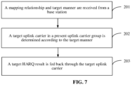
- FIG. 7 is a flowchart illustrating another method for feeding back a HARQ result according to an exemplary embodiment. The method may be applied to a terminal and includes the following steps.
- Step 201 a mapping relationship and a target manner are received from a base station, the mapping relationship being a mapping relationship between each downlink carrier group and each uplink carrier group and the target manner being a manner for acquiring a target uplink carrier from the each uplink carrier group.
- Step 202 the target uplink carrier in a present uplink carrier group is determined according to the target manner.
- Step 203 a target HARQ result is fed back through the target uplink carrier.
- Each downlink carrier group includes at least one downlink carrier, each uplink carrier group includes at least one uplink carrier, the target uplink carrier is an uplink carrier configured to carry the target HARQ result in the present uplink carrier group, and the target HARQ result includes HARQ results of downlink data carried on all the downlink carriers in a downlink carrier group corresponding to the present uplink carrier group.
- the terminal after receiving the mapping relationship and the target manner from the base station, may determine the target uplink carrier in the present uplink carrier group according to the target manner. Furthermore, the terminal may feed back the target HARQ result through the target uplink carrier.
- the mapping relationship may be a mapping relationship between each downlink carrier group and each uplink carrier group
- the target manner may be a manner for acquiring the target uplink carrier from the each uplink carrier group.
- Each downlink carrier group may include the at least one downlink carrier, each uplink carrier group may include the at least one uplink carrier, the target uplink carrier may be the uplink carrier configured to carry the target HARQ result in the present uplink carrier group, and the target HARQ result may include the HARQ results of the downlink data carried on all the downlink carriers in the downlink carrier group corresponding to the present uplink carrier group.
- the base station may send the mapping relationship and the target manner to the terminal through target signaling, and the terminal directly receives them.
- the mapping relationship may be a mapping relationship between each downlink carrier group and each uplink carrier group, and the target manner may be a manner for acquiring the target uplink carrier from the each uplink carrier group.
- the target uplink carrier may be an uplink carrier configured to carry the target HARQ result in the present uplink carrier group, and the target HARQ result may include the HARQ results of downlink data carried on all the downlink carriers in a downlink carrier group corresponding to the present uplink carrier group.
- the terminal may determine the target uplink carrier in the present uplink carrier group according to the target manner specified by the base station.
- the terminal may perform LBT on each uplink carrier in the present uplink carrier group according to the related art, thereby obtaining an LBT result corresponding to each uplink carri er.
- the terminal may determine the uplink carrier with the highest channel quality in the idle channel in the present uplink carrier group as the target uplink carrier according to the LBT result corresponding to each uplink carrier.
- the target uplink carrier may be an uplink carrier with the highest channel quality in the idle channel.
- the terminal may determine the uplink carrier CC3 as the target uplink carrier.
- Determining the target uplink carrier in such a target manner may improve accuracy of transmission.
- the target uplink carrier may also be determined in another target manner, and the target manner may be that an uplink carrier is selected from each uplink carrier group as the target uplink carrier according to a sequence that is notified through signaling or is predefined. Then, the terminal may number all uplink carriers in the present uplink carrier group according to a sequence from smallest to largest and then determine the first uplink carrier of which the LBT result is success as the target uplink carrier according to numbers of all the uplink carriers.
- the sequence notified through the signaling may be a sequence notified by the base station through target signaling to the terminal to select the uplink carrier as the target uplink carrier.
- the target signaling may be RRC signaling, system information, a MAC CE and physical-layer signaling.
- the base station may send the sequence from smallest to largest to the terminal through any signaling in the target signaling.
- the predefined sequence may be a sequence that has been defined for selecting the target uplink carrier in a communication protocol. For example, it has been specified in the communication protocol that the terminal may sequentially select the uplink carrier as the target uplink carrier according to the sequence from smallest to largest.
- the terminal may perform LBT on the uplink carrier CC1 and, if an LBT result is success, the terminal may determine the uplink carrier CC1 as the target uplink carrier; if the LBT result of the uplink carrier CC1 is failure, the terminal may continue performing LBT on the uplink carrier CC2 and, if an LBT result corresponding to the uplink carrier CC2 is success, the terminal may determine the uplink carrier CC2 as the target uplink carrier; and if the LBT result corresponding to the uplink carrier CC2 is failure, LBT may be continued to be performed on the uplink carrier CC3, etc. until the target uplink carrier is found.
- Determining the target uplink carrier in the second target manner may greatly reduce complexity of blind detection of the base station over a PUCCH.
- the terminal may select the target uplink carrier according to the LBT result, so that uncertain channel availability when the PUCCH is configured in an unauthorized carrier can be effectively alleviated, and reliability of a feedback on a HARQ result can be improved.
- the terminal can obtain the target uplink carrier in the present uplink carrier group in either manner. Assuming that the mapping relationship between each downlink carrier group and each uplink carrier group is as shown in Table 1 and the terminal obtains in any manner a target uplink carrier which is the uplink carrier CC3 from uplink carrier group 1 and obtains a target uplink carrier which is the uplink carrier CC5 from uplink carrier group 2, then, a mapping relationship among a downlink carrier group, an uplink carrier group and a target uplink carrier may be as shown in Table 3.
- Uplink carrier group Target uplink carrier First downlink carrier group 1 (downlink carrier CC1 to downlink carrier CC16) Uplink carrier group 1 (uplink carrier CC1 to uplink carrier CC3) Uplink carrier CC3 First downlink carrier group 2 (downlink carrier CC16 to downlink carrier CC32) Uplink carrier group 1 (uplink carrier CC4 and uplink carrier CC5) Uplink carrier CC5
- the terminal may feed back the target HARQ result through the target uplink carrier determined in the abovementioned step according to the related art. That is, the HARQ results of the downlink data carried on all the downlink carriers in the downlink carrier group corresponding to the present uplink carrier group are fed back through the target uplink carrier.
- the terminal may feed back HARQ results of downlink data carried on downlink carrier CC1 to downlink carrier CC16 through the uplink carrier CC3 and feed back HARQ results of downlink data carried on the downlink carrier CC16 to downlink carrier CC32 through uplink carrier CC5.
- the HARQ result may include an Acknowledgement (ACK) or a Negative Acknowledgement (NACK).
- ACK Acknowledgement
- NACK Negative Acknowledgement
- the base station upon when receiving the ACK, may determine that the corresponding downlink data has been successfully received by the terminal, and the base station, upon when receiving the NACK, may determine that the corresponding downlink data is not successfully received by the terminal and is required to be retransmitted.
- the problem that massive data has to be retransmitted because of a PUCCH CRC failure of the base station can be effectively alleviated, and reliability of a feedback on a HARQ result through a PUCCH in the LAA system can be improved.
- FIG. 8 is a flowchart illustrating another method for feeding back a HARQ result according to an exemplary embodiment. The method includes the following steps.
- Step 301 a base station groups all downlink carriers to obtain multiple downlink carrier groups.
- Step 302 the base station groups all uplink carriers to obtain multiple uplink carrier groups.
- Step 303 the base station establishes a mapping relationship between each downlink carrier group and each uplink carrier group.
- Step 304 the base station determines a target manner for acquiring a target uplink carrier from the each uplink carrier group.
- the target uplink carrier may be an uplink carrier configured to carry a target HARQ result in a present uplink carrier group, and the target HARQ result may include HARQ results of downlink data carried on all the downlink carriers in a downlink carrier group corresponding to the present uplink carrier group.
- the target manner may include that: an uplink carrier with highest channel quality in an idle channel in each uplink carrier group is determined as the target uplink carrier; or an uplink carrier is selected from each uplink carrier group as the target uplink carrier according to a sequence that is notified through signaling or is predefined.
- Step 305 the base station sends the mapping relationship and the target manner to a terminal through target signaling.
- the target signaling may be RRC signaling, system information, a MAC CE or physical-layer signaling, which is convenient for implementation and has high applicability.
- Step 306 the terminal determines the target uplink carrier in the present uplink carrier group according to the target manner.
- Step 307 the terminal feeds back the target HARQ result through the target uplink carrier.
- the base station when DC is implemented between an LTE system and an LAA system, if the base station fails in CRC over a PDCCH, only downlink data carried on all the downlink carriers in the downlink carrier group corresponding to the uplink carrier group is required to be retransmitted, so that the problem that massive downlink data has to be retransmitted because of a PUCCH CRC failure of the base station can be effectively alleviated, and reliability of a feedback on a HARQ result through a PUCCH in the LAA system can be improved.
- the terminal supports two PUCCHs.
- the downlink carrier CC1 to the downlink carrier CC16 may be divided into first downlink carrier group 1 and mapped to uplink carrier group 1 for transmission, and the downlink carrier CC16 to the downlink carrier CC32 may be divided into first downlink carrier group 2 and mapped to an uplink carrier group 2 for transmission.
- the uplink carrier CC1 to the uplink carrier CC3 may be divided into the uplink carrier group 1, and the uplink carrier CC4 and the uplink carrier CC5 may be divided into the uplink carrier group 2.
- the target manner may be that the uplink carrier with the highest channel quality in the idle channel in each uplink carrier group is determined as the target uplink carrier.
- the terminal may select the uplink carrier CC1 and uplink carrier CC4 which have the highest channel quality in the idle channel according to the LBT result to transmit PUCCH1 and PUCCH2 respectively, the PUCCH1 and the PUCCH2 correspondingly transmitting the HARQ results of the downlink data carried on all the downlink carriers in the first downlink carrier group 1 and the first downlink carrier group 2 respectively.
- the base station may feed back the HARQ results of the downlink data in different first downlink carrier groups through the target uplink carriers in different uplink carrier groups.
- DC is implemented between the LTE system and the LAA system
- the base station fails in CRC over a PDCCH
- only downlink data carried on all the downlink carriers in the downlink carrier group corresponding to the uplink carrier group is required to be retransmitted, so that the problem that massive data has to be retransmitted because of a PUCCH CRC failure of the base station can be effectively alleviated, and reliability of a feedback on a HARQ result through a PUCCH in the LAA system can be improved.
- the downlink carrier CC1 to the downlink carrier CC5 may be divided into the same group, i.e., a second downlink carrier group, for transmission.
- the uplink carrier CC1 and the uplink carrier CC2 may be divided into the uplink carrier group 1, and the uplink carrier CC3 and the uplink carrier CC4 may be divided into the uplink carrier group 2.
- the target manner may be that the uplink carrier with the highest channel quality in the idle channel in each uplink carrier group is determined as the target uplink carrier.
- the terminal may select the uplink carrier CC1 and uplink carrier CC3 which have the highest channel quality in the idle channel according to the LBT result to transmit a PUCCH1 and a PUCCH2 respectively, both the PUCCH1 and the PUCCH2 correspondingly transmitting the HARQ results of the downlink data carried on all the downlink carriers in the second downlink carrier group.
- the base station may feed back HARQ results of downlink data in all the downlink carriers through the target uplink carriers in different uplink carrier groups, and when the base station succeeds in CRC over a PDCCH, no downlink data is required to be retransmitted, so that reliability of a feedback on a HARQ result through a PUCCH in the LAA system can be improved.
- the terminal supports two PUCCHs. Considering that the number of the downlink carriers ranges from a second threshold to a first threshold, partial overlapping grouping may be adopted for the downlink carriers.
- the downlink data carried on the downlink carrier CC8 and the downlink carrier CC9 has higher priority.
- the downlink carrier CC1 to the downlink carrier CC9 may be divided into a group to obtain third downlink carrier group 1
- the downlink carrier CC17 to the downlink carrier CC32 may be divided into a group to obtain third downlink carrier group 2.
- the uplink carrier CC1 to the uplink carrier CC3 may be divided into the uplink carrier group 1
- the uplink carrier CC4 to the uplink carrier CC6 may be divided into the uplink carrier group 2.
- the target manner may be that the uplink carrier with the highest channel quality in the idle channel in each uplink carrier group may be determined as the target uplink carrier.
- the terminal may select the uplink carrier CC1 and uplink carrier CC5 which have the highest channel quality in the idle channel according to the LBT result to transmit PUCCH1 and PUCCH2 respectively, both the PUCCH1 and the PUCCH2 correspondingly transmitting the HARQ results of the downlink data carried on all the downlink carriers in the third downlink carrier group 1 and the third downlink carrier group 2.
- the base station may allocate the downlink carrier corresponding to the target data with higher priority into at least two third downlink carrier groups, and HARQ results of downlink data in different third downlink carrier groups may be fed back through the target uplink carriers in different uplink carrier groups. Reliability of feedback from the terminal on a HARQ result of the downlink data with high priority can be improved.
- each of the abovementioned method embodiments is expressed as a combination of a series of operations. Some steps may be executed in other sequences or at the same time according to the present disclosure.
- the present disclosure also provides an application function realization device and a corresponding embodiment.
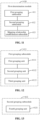
- FIG. 10 is a block diagram of a device for feeding back a HARQ result according to an exemplary embodiment.
- the device is applied to a base station.
- the device includes:
- the base station may send the mapping relationship between each downlink carrier group and each uplink carrier group and the target manner for acquiring the target uplink carrier from the each uplink carrier group to the terminal, and the terminal, after determining the target uplink carrier in the present uplink carrier group according to the target manner, may feed back the target HARQ result through the target uplink carrier
- the target uplink carrier may be an uplink carrier configured to carry the target HARQ result in the present uplink carrier group
- the target HARQ result may include the HARQ results of downlink data carried on all the downlink carriers in the downlink carrier group corresponding to the present uplink carrier group.
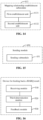
- FIG. 11 is a block diagram of another device for feeding back a HARQ result based on the embodiment shown in FIG. 10 .
- the first determination module 410 includes:
- the base station may group the downlink carriers and the uplink carriers respectively, thereby establishing the mapping relationship between each downlink carrier group and each uplink carrier group to ensure that the target HARQ result may subsequently be fed back through the target uplink carriers in different uplink carrier groups.
- the target HARQ result may include the HARQ results of the downlink data carried on all the downlink carriers in the downlink carrier group corresponding to the present uplink carrier group.
- FIG. 12 is a block diagram of another device for feeding back a HARQ result based on the embodiment shown in FIG. 11 .
- the first grouping submodule 411 may include:
- the base station may divide the downlink carriers into different downlink carrier groups according to the total number of the downlink carriers; when the total number of the downlink carriers is relatively large, non-overlapping grouping may be performed to obtain the target number of first downlink carrier groups; when the total number of the downlink carriers is relatively small, complete overlapping grouping may be performed to divide all the downlink carriers into a group, thereby obtaining the second downlink carrier group; and when the total number of the downlink carriers is proper, namely ranging from the second threshold to the first threshold, partial overlapping grouping may be performed to divide the downlink carriers carrying downlink data which have higher priority into at least two third downlink carrier groups.
- FIG. 13 is a block diagram of another device for feeding back a HARQ result based on the embodiment shown in FIG. 11 .
- the second grouping submodule 412 may include: a fourth grouping unit 4121, configured to group all the uplink carriers to obtain the target number of uplink carrier groups, any two uplink carrier groups including different uplink carriers and the target number being the number of PUCCHs supported by the terminal.
- the base station may perform non-overlapping grouping on the uplink carriers to establish the mapping relationship between uplink carrier groups and downlink carrier groups, thereby achieving high applicability.
- FIG. 14 is a block diagram of another device for feeding back a HARQ result based on the embodiment shown in FIG. 12 or FIG. 13 .
- the mapping relationship establishment submodule 413 may include:
- the mapping relationship that each downlink carrier group corresponds to each uplink carrier group one to one may be established; and when the number of the downlink carrier groups is 1, the mapping relationship that the downlink carrier group corresponds to each uplink carrier group may be established.
- the target manner may include that:
- the base station may specify a target manner for acquiring a target uplink carrier for a terminal, and furthermore, the terminal may determine a target uplink carrier required to carry a target HARQ result in a present uplink carrier group according to the target manner specified by the base station.
- the uncertainty of channel availability when the PUCCH is configured on an unauthorized carrier can be effectively alleviated.
- FIG. 15 is a block diagram of another device for feeding back a HARQ result based on the embodiment shown in FIG. 10 .
- the sending module 430 may include: a sending submodule 431, configured to send the mapping relationship and the target manner to the terminal through target signaling, the target signaling including at least one of:
- RRC signaling system information
- MAC CE physical-layer signaling
- the base station may send the mapping relationship and the target manner to the terminal through the target signaling, the target signaling including at least one of: the RRC signaling, the system information, the MAC CE and the physical-layer signaling. Convenience for implementation and high applicability are achieved.
- FIG. 16 is a block diagram of another device for feeding back a HARQ result according to an exemplary embodiment.
- the device is applied to a terminal.
- the device includes:
- the terminal after receiving the mapping relationship and the target manner from the base station, may determine the target uplink carrier in the present uplink carrier group according to the target manner. Furthermore, the terminal may feed back the target HARQ result through the target uplink carrier.
- the mapping relationship may be a mapping relationship between each downlink carrier group and each uplink carrier group
- the target manner may be a manner for acquiring the target uplink carrier from the each uplink carrier group.
- Each downlink carrier group may include at least one downlink carrier, each uplink carrier group may include at least one uplink carrier, the target uplink carrier may be an uplink carrier configured to carry the target HARQ result in the present uplink carrier group, and the target HARQ result may include the HARQ results of the downlink data carried on all the downlink carriers in the downlink carrier group corresponding to the present uplink carrier group.
- the target manner may include that:
- FIG. 17 is a block diagram of another device for feeding back a HARQ result based on the embodiment shown in FIG. 16 .
- the third determination module 520 may include:
- FIG. 18 is a block diagram of another device for feeding back a HARQ result based on the embodiment shown in FIG. 16 .
- the third determination module 520 may include:
- the target manner provided for the terminal by the base station may include that: an uplink carrier with the highest channel quality in the idle channel in each uplink carrier group is determined as the target uplink carrier; or an uplink carrier is selected from each uplink carrier group as the target uplink carrier according to the sequence that is notified through the signaling or is predefined.
- the terminal may perform LBT on each uplink carrier in the present uplink carrier group according to the target manner to obtain an LBT result, thereby selecting the uplink carrier with the highest channel quality in the idle channel as the target uplink carrier according to the LBT result.
- all the uplink carriers in the present uplink carrier group may be numbered according to the sequence from smallest to largest, and a first uplink carrier of which the LBT result is success may be determined as the target uplink carrier according to the sequencing numbers.
- the terminal may select the target uplink carrier according to the LBT result, so that the problem of channel availability uncertainty when the PUCCH is configured on an unauthorized carrier can be effectively alleviated, and reliability of a feedback on a HARQ result can be improved.
- the device embodiments substantially correspond to the method embodiments, and thus the related parts may refer to part of descriptions of the method embodiments.
- the device embodiments described above are only schematic, units described as separate parts therein can be physically separated or not; and parts displayed as units can be physical units or not, which namely may be located in the same place or may be distributed to multiple network units. Part or all of the modules therein may be selected according to a practical requirement to achieve the purpose of the solutions of the present disclosure. Those of ordinary skill in the art may understand and implement without creative work.
- the present disclosure also provides a computer-readable storage medium, which can have a computer program stored thereon for executing any method for feeding back a HARQ result applied to a base station side.
- the present disclosure also provides a computer-readable storage medium, which can have a computer program stored thereon for executing any method for feeding back a HARQ result applied to a terminal side.
- the present disclosure also provides a device for feeding back a HARQ result, which is applied to a base station and includes:
- FIG. 19 is a structure diagram of a device 1900 for feeding back a HARQ result according to an exemplary embodiment of the present disclosure.
- the device 1900 may be provided as a base station.
- the device 1900 includes a processing component 1922, a wireless transmission/receiving component 1924, an antenna component 1926 and a wireless interface-specific signal processing part, and the processing component 1922 may further include one or more processors.
- One processor in the processing component 1922 may be configured to:
- the present disclosure also provides a device for feeding back a HARQ result, which is applied to a terminal and includes:
- FIG. 20 is a structure diagram of a device for feeding back a HARQ result according to an exemplary embodiment.
- FIG. 20 illustrates a device 2000 for feeding back a HARQ result according to an exemplary embodiment.
- the device 2000 may be a terminal such as a computer, a mobile phone, a digital broadcast terminal, a messaging device, a gaming console, a tablet, a medical device, exercise equipment and a personal digital assistant.
- the device 2000 may include one or more of the following components: a processing component 2001, a memory 2002, a power component 2003, a multimedia component 2004, an audio component 2005, an Input/Output (I/O) interface 2006, a sensor component 2007, and a communication component 2008.
- a processing component 2001 may include one or more of the following components: a processing component 2001, a memory 2002, a power component 2003, a multimedia component 2004, an audio component 2005, an Input/Output (I/O) interface 2006, a sensor component 2007, and a communication component 2008.
- the processing component 2001 is typically configured to control overall operations of the device 2000, such as the operations associated with display, telephone calls, data communications, camera operations, and recording operations.
- the processing component 2001 may include one or more processors 2009 to execute instructions to perform all or part of the steps in the abovementioned method.
- the processing component 2001 may include one or more modules which facilitate interaction between the processing component 2001 and other components.
- the processing component 2001 may include a multimedia module to facilitate interaction between the multimedia component 2004 and the processing component 2001.
- the memory 2002 is configured to store various types of data to support the operation of the device 2000. Examples of such data may include instructions for any application programs or methods operated on the device 2000, contact data, phonebook data, messages, pictures, video, etc.
- the memory 2002 may be implemented by any type of volatile or non-volatile memory devices, or a combination thereof, such as a Static Random Access Memory (SRAM), an Electrically Erasable Programmable Read-Only Memory (EEPROM), an Erasable Programmable Read-Only Memory (EPROM), a Programmable Read-Only Memory (PROM), a Read-Only Memory (ROM), a magnetic memory, a flash memory, and a magnetic or optical disk.
- SRAM Static Random Access Memory
- EEPROM Electrically Erasable Programmable Read-Only Memory
- EPROM Erasable Programmable Read-Only Memory
- PROM Programmable Read-Only Memory
- ROM Read-Only Memory
- magnetic memory a magnetic memory
- flash memory and a magnetic or optical disk.
- the power component 2003 may provide power for various components of the device 2000.
- the power component 2003 may include a power management system, one or more power supplies, and other components associated with generation, management and distribution of power for the device 2000.
- the multimedia component 2004 may include a screen providing an output interface between the device 2000 and a user.
- the screen may include a Liquid Crystal Display (LCD) and a Touch Panel (TP). If the screen includes the TP, the screen may be implemented as a touch screen to receive an input signal from the user.
- the TP includes one or more touch sensors to sense touches, swipes and gestures on the TP. The touch sensors cannot only sense a boundary of a touch or swipe action but also detect a duration and pressure associated with the touch or swipe action.
- the multimedia component 2004 includes a front camera and/or a rear camera. The front camera and/or the rear camera may receive external multimedia data when the device 2000 is in an operation mode, such as a photographing mode or a video mode. Each of the front camera and the rear camera may be a fixed optical lens system or have focusing and optical zooming capabilities.
- the audio component 2005 is configured to output and/or input an audio signal.
- the audio component 2005 includes a Microphone (MIC), and the MIC is configured to receive an external audio signal when the device 2000 is in the operation mode, such as a call mode, a recording mode and a voice recognition mode.
- the received audio signal may further be stored in the memory 2002 or sent through the communication component 2008.
- the audio component 2005 further includes a speaker configured to output the audio signal.
- the I/O interface 2006 may provide an interface between the processing component 2001 and a peripheral interface module, and the peripheral interface module may be a keyboard, a click wheel, a button and the like.
- the button may include, but not limited to: a home button, a volume button, a starting button and a locking button.
- the sensor component 2007 may include one or more sensors configured to provide status assessment in various aspects for the device 2000. For instance, the sensor component 2007 may detect an on/off status of the device 2000 and relative positioning of components, such as a display and small keyboard of the device 2000, and the sensor component 2007 may further detect a change in a position of the device 2000 or a component of the device 2000, presence or absence of contact between the user and the device 2000, orientation or acceleration/deceleration of the device 2000 and a change in temperature of the device 2000.
- the sensor component 2007 may include a proximity sensor configured to detect presence of an obj ect nearby without any physical contact.
- the sensor component 2007 may also include a light sensor, such as a Complementary Metal Oxide Semiconductor (CMOS) or Charge Coupled Device (CCD) image sensor, configured for use in an imaging application.
- CMOS Complementary Metal Oxide Semiconductor
- CCD Charge Coupled Device
- the sensor component 2007 may also include an acceleration sensor, a gyroscope sensor, a magnetic sensor, a pressure sensor or a temperature sensor.
- the communication component 2008 is configured to facilitate wired or wireless communication between the device 2000 and another device.
- the device 2000 may access a communication-standard-based wireless network, such as a Wireless Fidelity (WiFi) network, a 2nd-Generation (2G) or 3rd-Generation (3G) network or a combination thereof.
- WiFi Wireless Fidelity
- 2G 2nd-Generation
- 3G 3rd-Generation
- the communication component 2008 receives a broadcast signal or broadcast associated information from an external broadcast management system through a broadcast channel.
- the communication component 2008 further includes a Near Field Communication (NFC) module to facilitate short-range communication.
- NFC Near Field Communication
- the NFC module may be implemented based on a Radio Frequency Identification (RFID) technology, an Infrared Data Association (IrDA) technology, an Ultra-WideBand (UWB) technology, a Bluetooth (BT) technology and another technology.
- RFID Radio Frequency Identification
- IrDA Infrared Data Association
- UWB Ultra-WideBand
- BT Bluetooth
- the device 2000 may be implemented by one or more Application Specific Integrated Circuits (ASICs), Digital Signal Processors (DSPs), Digital Signal Processing Devices (DSPDs), Programmable Logic Devices (PLDs), Field Programmable Gate Arrays (FPGAs), controllers, micro-controllers, microprocessors or other electronic components, and is configured to execute the abovementioned method.
- ASICs Application Specific Integrated Circuits
- DSPs Digital Signal Processors
- DSPDs Digital Signal Processing Devices
- PLDs Programmable Logic Devices
- FPGAs Field Programmable Gate Arrays
- controllers micro-controllers, microprocessors or other electronic components, and is configured to execute the abovementioned method.
- non-transitory computer-readable storage medium including instructions, such as the memory 2002 including instructions, and the instructions may be executed by the processor 2009 of the device 2000 to implement the abovementioned method.
- the non-transitory computer-readable storage medium may be a Read-Only Memory (ROM), a Random Access Memory (RAM), a Compact Disc Read-Only Memory (CD-ROM), a magnetic tape, a floppy disc, an optical data storage device and the like.
- the instructions in the storage medium may be executed by the processor to enable the device 2000 to implement any method for feeding back a HARQ result on a terminal side.
Landscapes
- Engineering & Computer Science (AREA)
- Signal Processing (AREA)
- Computer Networks & Wireless Communication (AREA)
- Mobile Radio Communication Systems (AREA)
Claims (8)
- Verfahren zur Rückführung eines Hybrid Automatic Repeat ReQuest (HARQ)-Ergebnisses, das von einer Basisstation implementiert wird, wobei das Verfahren Folgendes umfasst:Bestimmen (101) einer Zuordnungsbeziehung zwischen jeder Downlink-Trägergruppe und jeder Uplink-Trägergruppe, wobei die jeweilige Downlink-Trägergruppe mindestens einen Downlink-Träger und die jeweilige Uplink-Trägergruppe mindestens einen Uplink-Träger umfasst;Bestimmen (102) einer Zielart zum Erfassen eines Ziel-Uplink-Trägers von jeder Uplink-Trägergruppe, wobei der Ziel-Uplink-Träger ein Uplink-Träger ist, der so konfiguriert ist, dass er ein Ziel-HARQ-Ergebnis in einer gegenwärtigen Uplink-Trägergruppe trägt und das Ziel-HARQ-Ergebnis HARQ-Ergebnisse von Downlink-Daten umfasst, die auf allen Downlink-Trägern in einer Downlink-Trägergruppe getragen werden, die der gegenwärtigen Uplink-Trägergruppe entspricht; undSenden (103) der Zuordnungsbeziehung und der Zielart an ein Endgerät, damit das Endgerät das Ziel-HARQ-Ergebnis über den Ziel-Uplink-Träger zurücksenden kann, nachdem der Ziel-Uplink-Träger in der gegenwärtigen Uplink-Trägergruppe gemäß der Zielart bestimmt wurde,wobei das Bestimmen (101) der Zuordnungsbeziehung zwischen der jeweiligen Downlink-Trägergruppe und der jeweiligen Uplink-Trägergruppe Folgendes umfasst:Gruppierung (101-1) aller Downlink-Träger, um mehrere Downlink-Trägergruppen zu erhalten;Gruppierung (101-2) aller Uplink-Träger, um mehrere Uplink-Trägergruppen zu erhalten; undHerstellung (101-3) der Zuordnungsbeziehung zwischen jeder Downlink-Trägergruppe und jeder Uplink-Trägergruppe,dadurch gekennzeichnet, dass das Gruppieren (101-1) aller Downlink-Träger, um die Mehrfach-Downlink-Trägergruppen zu erhalten, Folgendes umfasst:wenn eine Gesamtanzahl aller Uplink-Träger einen ersten Schwellenwert überschreitet, Aufteilen aller Uplink-Träger in eine Zielanzahl von ersten Uplink-Trägergruppen, wobei zwei beliebige erste Uplink-Trägergruppen unterschiedliche Uplink-Träger umfassen und die Zielanzahl die Anzahl der von dem Endgerät unterstützten physikalischen Uplink-Steuerkanäle (PUCCHs) ist;wenn die Gesamtanzahl aller Downlink-Träger kleiner als ein zweiter Schwellenwert ist, Aufteilen aller Downlink-Träger in eine selbe Gruppe, um eine zweite Downlink-Trägergruppe zu erhalten, wobei der erste Schwellenwert größer als der zweite Schwellenwert ist; undwenn die Gesamtanzahl aller Downlink-Träger im Bereich zwischen dem zweiten Schwellenwert und dem ersten Schwellenwert liegt, Aufteilen aller Downlink-Träger in eine Zielanzahl dritter Downlink-Trägergruppen, wobei ein Downlink-Träger, der so konfiguriert ist, dass er Zieldaten mit einer höheren Priorität als der vorbestimmten Priorität trägt, zu mindestens zwei dritten Downlink-Trägergruppen gehört.
- Verfahren nach Anspruch 1, wobei das Herstellen der Zuordnungsbeziehung zwischen der jeweiligen Downlink-Trägergruppe und der jeweiligen Uplink-Trägergruppe Folgendes umfasst:wenn eine Gruppenanzahl der Downlink-Trägergruppen die Zielanzahl ist, Herstellen der Zuordnungsbeziehung, dass die jeweilige Downlink-Trägergruppe der jeweiligen Uplink-Trägergruppe eins zu eins entspricht; undwenn die Gruppenanzahl der Downlink-Trägergruppen 1 ist, Herstellung der Zuordnungsbeziehung, dass die Downlink-Trägergruppe der jeweiligen Uplink-Trägergruppe entspricht.
- Verfahren nach Anspruch 1, wobei die Zielart umfasst, dass:ein Uplink-Träger mit der höchsten Kanalqualität in einem freien Kanal in jeder Uplink-Trägergruppe als Ziel-Uplink-Träger bestimmt wird; oderein Uplink-Träger aus jeder Uplink-Trägergruppe als der Ziel-Uplink-Träger gemäß einer Sequenz ausgewählt wird, die durch Signalisierung mitgeteilt wird oder vordefiniert ist.
- Verfahren nach Anspruch 1, wobei das Senden der Zuordnungsbeziehung und der Zielart an das Endgerät Folgendes umfasst:
Senden der Zuordnungsbeziehung und der Zielart an das Endgerät durch Zielsignalisierung, wobei die Zielsignalisierung mindestens eines der Folgenden umfasst:
Radio Resource Control (RRC)-Signalisierung, Systeminformationen, Media Access Control (MAC), Control Element (CE) und Physical-Layer-Signalisierung. - Verfahren zur Rückführung eines Hybrid Automatic Repeat ReQuest (HARQ)-Ergebnisses, das von einem Endgerät implementiert wird, wobei das Verfahren Folgendes umfasst:Empfangen (201) einer Zuordnungsbeziehung und einer Zielart von einer Basisstation, wobei die Zuordnungsbeziehung eine Zuordnungsbeziehung zwischen jeder Downlink-Trägergruppe und jeder Uplink-Trägergruppe ist und die Zielart eine Art zum Erfassen eines Ziel-Uplink-Trägers von jeder Uplink-Trägergruppe ist;Bestimmen (202) des Ziel-Uplink-Trägers in einer gegenwärtigen Uplink-Trägergruppe gemäß der Zielart; undRückführung (203) eines Ziel-HARQ-Ergebnisses über den Ziel-Uplink-Träger,wobei jede Downlink-Trägergruppe mindestens einen Downlink-Träger umfasst, jede Uplink-Trägergruppe mindestens einen Uplink-Träger umfasst, der Ziel-Uplink-Träger ein Uplink-Träger ist, der so konfiguriert ist, dass er das Ziel-HARQ-Ergebnis in der gegenwärtigen Uplink-Trägergruppe trägt, und das Ziel-HARQ-Ergebnis HARQ-Ergebnisse von Downlink-Daten umfasst, die auf allen Downlink-Trägern in einer Downlink-Trägergruppe getragen werden, die der gegenwärtigen Uplink-Trägergruppe entspricht,wobei die Zielart umfasst, dass:ein Uplink-Träger mit der höchsten Kanalqualität in einem freien Kanal in jeder Uplink-Trägergruppe als Ziel-Uplink-Träger bestimmt wird; oderein Uplink-Träger aus jeder Uplink-Trägergruppe als der Ziel-Uplink-Träger gemäß einer Sequenz ausgewählt wird, die durch Signalisierung mitgeteilt wird oder vordefiniert ist,dadurch gekennzeichnet, dass das Bestimmen des Ziel-Uplink-Trägers in der gegenwärtigen Uplink-Trägergruppe gemäß der Zielart Folgendes umfasst:für den Fall, dass die Zielart darin besteht, dass der Uplink-Träger mit der höchsten Kanalqualität im freien Kanal in jeder Uplink-Trägergruppe als Ziel-Uplink-Träger bestimmt wird,Durchführen von Listen Before Talk (LBT) auf jedem Uplink-Träger in der gegenwärtigen Uplink-Trägergruppe, um ein LBT-Ergebnis zu erhalten; undAuswählen des Uplink-Trägers mit der höchsten Kanalqualität im freien Kanal aus der gegenwärtigen Uplink-Trägergruppe als Ziel-Uplink-Träger gemäß dem LBT-Ergebnis;
oderdadurch gekennzeichnet, dass das Bestimmen des Ziel-Uplink-Trägers in der gegenwärtigen Uplink-Trägergruppe gemäß der Zielart Folgendes umfasst:
für den Fall, dass die Zielart darin besteht, dass der Uplink-Träger aus jeder Uplink-Trägergruppe als Ziel-Uplink-Träger gemäß der durch die Signalisierung mitgeteilten oder vordefinierten Sequenz ausgewählt wird,Nummerierung aller Uplink-Träger in der gegenwärtigen Uplink-Trägergruppe gemäß einer Reihenfolge vom kleinsten zum größten; undBestimmen eines ersten Uplink-Trägers, dessen LBT-Ergebnis ein Erfolg ist, als Ziel-Uplink-Träger gemäß den Anzahlen aller Uplink-Träger. - Vorrichtung zur Rückführung eines Hybrid Automatic Repeat ReQuest (HARQ)-Ergebnisses, das von einer Basisstation implementiert wird, wobei die Vorrichtung Folgendes umfasst:ein erstes Bestimmungsmodul (410), das so konfiguriert ist, dass es eine Zuordnungsbeziehung zwischen jeder Downlink-Trägergruppe und jeder Uplink-Trägergruppe bestimmt, wobei jede Downlink-Trägergruppe mindestens einen Downlink-Träger umfasst und jede Uplink-Trägergruppe mindestens einen Uplink-Träger umfasst;ein zweites Bestimmungsmodul (420), das so konfiguriert ist, dass es eine Zielart zum Erfassen eines Ziel-Uplink-Trägers von jeder Uplink-Trägergruppe bestimmt, wobei der Ziel-Uplink-Träger ein Uplink-Träger ist, der so konfiguriert ist, dass er ein Ziel-HARQ-Ergebnis in einer gegenwärtigen Uplink-Trägergruppe trägt und das Ziel-HARQ-Ergebnis HARQ-Ergebnisse von Downlink-Daten umfasst, die auf allen Downlink-Trägern in einer Downlink-Trägergruppe getragen werden, die der gegenwärtigen Uplink-Trägergruppe entspricht; undein Sendemodul (430), das so konfiguriert ist, dass es die Zuordnungsbeziehung und die Zielart an ein Endgerät sendet, damit das Endgerät das Ziel-HARQ-Ergebnis über den Ziel-Uplink-Träger zurücksenden kann, nachdem der Ziel-Uplink-Träger in der gegenwärtigen Uplink-Trägergruppe gemäß der Zielart bestimmt wurde,wobei das erste Bestimmungsmodul 410 Folgendes umfasst:ein erstes Gruppierungssubmodul (411), das so konfiguriert ist, dass es alle Downlink-Träger gruppiert, um mehrere Downlink-Trägergruppen zu erhalten;ein zweites Gruppierungssubmodul (412), das so konfiguriert ist, dass es alle Uplink-Träger gruppiert, um mehrere Uplink-Trägergruppen zu erhalten; undein Submodul (413) zum Einrichten der Zuordnungsbeziehung, das so konfiguriert ist, dass es die Zuordnungsbeziehung zwischen jeder Downlink-Trägergruppe und jeder Uplink-Trägergruppe einrichtet,dadurch gekennzeichnet, dass das erste Gruppierungssubmodul (411) Folgendes umfasst:eine erste Gruppierungseinheit (4111), die so konfiguriert ist, dass sie, wenn eine Gesamtanzahl aller Uplink-Träger einen ersten Schwellenwert überschreitet, alle Uplink-Träger in eine Zielanzahl von ersten Uplink-Trägergruppen aufteilt, wobei zwei beliebige erste Uplink-Trägergruppen unterschiedliche Uplink-Träger umfassen und die Zielanzahl die Anzahl der von dem Endgerät unterstützten physikalischen Uplink-Steuerkanäle (PUCCHs) ist;eine zweite Gruppierungseinheit (4112), die so konfiguriert ist, dass sie, wenn die Gesamtanzahl aller Downlink-Träger kleiner als ein zweiter Schwellenwert ist, alle Downlink-Träger in eine selbe Gruppe unterteilt, um eine zweite Downlink-Trägergruppe zu erhalten, wobei der erste Schwellenwert größer als der zweite Schwellenwert ist; undeine dritte Gruppierungseinheit (4113), die so konfiguriert ist, dass sie, wenn die Gesamtanzahl aller Downlink-Träger im Bereich zwischen dem zweiten Schwellenwert und dem ersten Schwellenwert liegt, alle Downlink-Träger in eine Zielanzahl dritter Downlink-Trägergruppen aufteilt, wobei ein Downlink-Träger, der so konfiguriert ist, dass er Zieldaten mit einer höheren Priorität als der vorbestimmten Priorität trägt, zu mindestens zwei dritten Downlink-Trägergruppen gehört.
- Vorrichtung zur Rückführung eines Hybrid Automatic Repeat reQuest (HARQ)-Ergebnisses, das von einem Endgerät implementiert wird, wobei die Vorrichtung Folgendes umfasst:ein Empfangsmodul (510), das so konfiguriert ist, dass es eine Zuordnungsbeziehung und eine Zielart von einer Basisstation empfängt, wobei die Zuordnungsbeziehung eine Zuordnungsbeziehung zwischen jeder Downlink-Trägergruppe und jeder Uplink-Trägergruppe ist und die Zielart eine Art zum Erfassen eines Ziel-Uplink-Trägers von jeder Uplink-Trägergruppe ist;ein drittes Bestimmungsmodul (520), das so konfiguriert ist, dass es den Ziel-Uplink-Träger in einer gegenwärtigen Uplink-Trägergruppe gemäß der Zielart bestimmt; undein Rückführungsmodul (530), das so konfiguriert ist, dass es ein Ziel-HARQ-Ergebnis über den Ziel-Uplink-Träger zurückführt,wobei jede Downlink-Trägergruppe mindestens einen Downlink-Träger umfasst, jede Uplink-Trägergruppe mindestens einen Uplink-Träger umfasst, der Ziel-Uplink-Träger ein Uplink-Träger ist, der so konfiguriert ist, dass er das Ziel-HARQ-Ergebnis in der gegenwärtigen Uplink-Trägergruppe trägt, und das Ziel-HARQ-Ergebnis HARQ-Ergebnisse von Downlink-Daten umfasst, die auf allen Downlink-Trägern in einer Downlink-Trägergruppe getragen werden, die der gegenwärtigen Uplink-Trägergruppe entspricht,wobei die Zielart umfasst, dass:ein Uplink-Träger mit der höchsten Kanalqualität in einem freien Kanal in jeder Uplink-Trägergruppe als Ziel-Uplink-Träger bestimmt wird; oderein Uplink-Träger aus jeder Uplink-Trägergruppe als der Ziel-Uplink-Träger gemäß einer Sequenz ausgewählt wird, die durch Signalisierung mitgeteilt wird oder vordefiniert ist,dadurch gekennzeichnet, dass das dritte Bestimmungsmodul (520) Folgendes umfasst:ein erstes Ausführungssubmodul (521), das so konfiguriert ist, dass es für den Fall, dass die Zielart darin besteht, dass der Uplink-Träger mit der höchsten Kanalqualität in dem freien Kanal in jeder Uplink-Trägergruppe als der Ziel-Uplink-Träger bestimmt wird, Durchführen von Listen Before Talk (LBT) auf jedem Uplink-Träger in der gegenwärtigen Uplink-Trägergruppe, um ein LBT-Ergebnis zu erhalten; undein erstes Bestimmungssubmodul (522), das so konfiguriert ist, dass es den Uplink-Träger mit der höchsten Kanalqualität im freien Kanal aus der gegenwärtigen Uplink-Trägergruppe als den Ziel-Uplink-Träger gemäß dem LBT-Ergebnis auswählt;oder, dadurch gekennzeichnet, dass das dritte Bestimmungsmodul (520) Folgendes umfasst:ein zweites Ausführungssubmodul (523), das so konfiguriert ist, dass es für den Fall, dass die Zielart darin besteht, dass der Uplink-Träger aus jeder Uplink-Trägergruppe als Ziel-Uplink-Träger gemäß der durch die Signalisierung mitgeteilten oder vordefinierten Sequenz ausgewählt wird, Nummerierung aller Uplink-Träger in der gegenwärtigen Uplink-Trägergruppe gemäß einer Sequenz vom kleinsten zum größten; undein zweites Bestimmungssubmodul (524), das so konfiguriert ist, dass es einen ersten Uplink-Träger, bei dem ein LBT-Ergebnis erfolgreich ist, als den Ziel-Uplink-Träger gemäß den Anzahlen aller Uplink-Träger bestimmt.
- Computerlesbares Speichermedium, das Anweisungen umfasst, die, wenn sie von einem Computer ausgeführt werden, den Computer veranlassen, das Verfahren nach einem der vorstehenden Ansprüche 1 bis 5 auszuführen.
Applications Claiming Priority (1)
| Application Number | Priority Date | Filing Date | Title |
|---|---|---|---|
| PCT/CN2017/094964 WO2019019171A1 (zh) | 2017-07-28 | 2017-07-28 | 一种混合自动重传请求结果的反馈方法及装置 |
Publications (3)
| Publication Number | Publication Date |
|---|---|
| EP3661088A1 EP3661088A1 (de) | 2020-06-03 |
| EP3661088A4 EP3661088A4 (de) | 2020-07-22 |
| EP3661088B1 true EP3661088B1 (de) | 2023-10-25 |
Family
ID=65039253
Family Applications (1)
| Application Number | Title | Priority Date | Filing Date |
|---|---|---|---|
| EP17918788.5A Active EP3661088B1 (de) | 2017-07-28 | 2017-07-28 | Hybrides automatisches wiederholungsanforderungsergebnisrückkopplungsverfahren und vorrichtung |
Country Status (4)
| Country | Link |
|---|---|
| US (1) | US11368255B2 (de) |
| EP (1) | EP3661088B1 (de) |
| CN (1) | CN109451791B (de) |
| WO (1) | WO2019019171A1 (de) |
Families Citing this family (4)
| Publication number | Priority date | Publication date | Assignee | Title |
|---|---|---|---|---|
| CN111771407B (zh) * | 2018-02-12 | 2023-11-17 | 华为技术有限公司 | 一种通信方法、通信设备及计算机程序存储介质 |
| US11582077B2 (en) * | 2019-02-25 | 2023-02-14 | Huawei Technologies Co., Ltd. | Systems and methods for transmission of uplink control information over multiple carriers in unlicensed spectrum |
| CN113839756A (zh) * | 2020-06-24 | 2021-12-24 | 中兴通讯股份有限公司 | Pucch资源分配方法、uci信息发送方法和装置 |
| US12432786B2 (en) * | 2021-12-23 | 2025-09-30 | Qualcomm Incorporated | Uplink (UL) transmission in random access channel (RACH) on flexible cell |
Family Cites Families (13)
| Publication number | Priority date | Publication date | Assignee | Title |
|---|---|---|---|---|
| US8693383B2 (en) * | 2005-03-29 | 2014-04-08 | Qualcomm Incorporated | Method and apparatus for high rate data transmission in wireless communication |
| CN101064592A (zh) * | 2006-04-29 | 2007-10-31 | 华为技术有限公司 | 避免数字用户线收发器虚假初始化的方法 |
| EP2408247B1 (de) * | 2009-03-13 | 2019-07-31 | Huawei Technologies Co., Ltd. | Verfahren zur betriebsmittelverteilung, verfahren zur datenübertragung, basisstation und endgerät |
| US9084206B2 (en) * | 2009-06-23 | 2015-07-14 | Samsung Electronics Co., Ltd | Method and apparatus for controlling uplink transmission power in wireless communication system |
| CN101998584B (zh) * | 2009-08-12 | 2013-07-31 | 电信科学技术研究院 | 一种物理下行控制信道的控制方法、装置和系统 |
| KR20110036479A (ko) | 2009-10-01 | 2011-04-07 | 삼성전자주식회사 | 이동통신 시스템에서 harq 피드백을 처리하는 방법 및 장치 |
| US9083501B2 (en) | 2010-04-05 | 2015-07-14 | Qualcomm Incorporated | Feedback of control information for multiple carriers |
| CN102215093B (zh) * | 2010-04-09 | 2016-03-02 | 中兴通讯股份有限公司 | 下行传输的反馈方法、基站及用户终端 |
| CN103929800B (zh) * | 2013-01-11 | 2017-09-29 | 电信科学技术研究院 | 一种pucch功率控制方法及装置 |
| CN103974319B (zh) | 2013-01-29 | 2017-08-11 | 电信科学技术研究院 | 载波聚合下的功率余量上报方法和设备 |
| EP3125459B1 (de) * | 2014-03-24 | 2019-08-28 | LG Electronics Inc. | Kommunikationsverfahren für duale konnektivität und vorrichtung dafür |
| CN105991260B (zh) | 2015-01-30 | 2019-07-23 | 上海诺基亚贝尔股份有限公司 | 传输针对大规模载波聚合的下行控制信令的方法和装置 |
| US10912082B2 (en) * | 2016-04-19 | 2021-02-02 | Lg Electronics Inc. | Ways for supporting multiple TTIs |
-
2017
- 2017-07-28 CN CN201780000742.6A patent/CN109451791B/zh active Active
- 2017-07-28 WO PCT/CN2017/094964 patent/WO2019019171A1/zh not_active Ceased
- 2017-07-28 EP EP17918788.5A patent/EP3661088B1/de active Active
- 2017-07-28 US US16/632,876 patent/US11368255B2/en active Active
Also Published As
| Publication number | Publication date |
|---|---|
| EP3661088A4 (de) | 2020-07-22 |
| EP3661088A1 (de) | 2020-06-03 |
| US11368255B2 (en) | 2022-06-21 |
| CN109451791A (zh) | 2019-03-08 |
| US20200213042A1 (en) | 2020-07-02 |
| WO2019019171A1 (zh) | 2019-01-31 |
| CN109451791B (zh) | 2021-08-31 |
Similar Documents
| Publication | Publication Date | Title |
|---|---|---|
| US20230362739A1 (en) | Communication method, communication apparatus and storage medium | |
| EP4106437B1 (de) | Datenübertragungsverfahren und datenübertragungsvorrichtung | |
| EP4250613B1 (de) | Informationsrückkopplungsverfahren und -vorrichtung | |
| US12021629B2 (en) | Hybrid automatic repeat request feedback method and device | |
| US11503625B2 (en) | Method and apparatus for transmitting data | |
| EP3751890A1 (de) | Verfahren und vorrichtung zur koexistenzinterferenzkoordination in einem gerät sowie benutzerausrüstung und kommunikationsvorrichtung | |
| US11350394B2 (en) | Resource configuration method, apparatus, user equipment, and base station | |
| CN106788936B (zh) | 信息反馈方法、装置、用户设备和基站 | |
| JP7315795B2 (ja) | ビーム失敗要求リソース割り当て方法、装置および記憶媒体 | |
| EP3787324A1 (de) | Verfahren und vorrichtung für harq-rückkopplung | |
| EP3836448B1 (de) | Verfahren und vorrichtung zur übertragung von harq-rückkopplungsinformation, basisstation und endgerät | |
| US12010065B2 (en) | Method for transmitting HARQ feedback information, terminal, and base station | |
| CN109196805B (zh) | 传输重传码本的方法及装置 | |
| EP3621231B1 (de) | Harq-feedback-verfahren und -einrichtung, vorrichtung, und computerlesbares speichermedium | |
| CN111095973A (zh) | 通信失败处理方法、通信失败处理装置及存储介质 | |
| US11368255B2 (en) | Hybrid automatic repeat request result feedback method and device | |
| US11310694B2 (en) | Method and device for receiving downlink data during RRC inactive state | |
| US11923989B2 (en) | Uplink feedback method and apparatus, terminal, base station and storage medium | |
| US11431366B2 (en) | Data transmission method and device | |
| US12438643B2 (en) | Unlicensed frequency band feedback method, unlicensed frequency band feedback apparatus, and storage medium | |
| US12294987B2 (en) | Method and apparatus for controlling pre-configured resource, and method and apparatus for data transmission | |
| EP3672316B1 (de) | Verfahren und vorrichtung zur signalisierungsdetektion, benutzergerät und basisstation | |
| CN116210186B (zh) | 一种harq-ack码本生成和接收方法、装置、设备及存储介质 | |
| EP4668638A1 (de) | Verfahren und vorrichtung zur kommunikation über einen gemeinsam genutzten physikalischen uplink-kanal (pusch) und speichermedium |
Legal Events
| Date | Code | Title | Description |
|---|---|---|---|
| STAA | Information on the status of an ep patent application or granted ep patent |
Free format text: STATUS: THE INTERNATIONAL PUBLICATION HAS BEEN MADE |
|
| PUAI | Public reference made under article 153(3) epc to a published international application that has entered the european phase |
Free format text: ORIGINAL CODE: 0009012 |
|
| STAA | Information on the status of an ep patent application or granted ep patent |
Free format text: STATUS: REQUEST FOR EXAMINATION WAS MADE |
|
| 17P | Request for examination filed |
Effective date: 20200221 |
|
| AK | Designated contracting states |
Kind code of ref document: A1 Designated state(s): AL AT BE BG CH CY CZ DE DK EE ES FI FR GB GR HR HU IE IS IT LI LT LU LV MC MK MT NL NO PL PT RO RS SE SI SK SM TR |
|
| AX | Request for extension of the european patent |
Extension state: BA ME |
|
| A4 | Supplementary search report drawn up and despatched |
Effective date: 20200623 |
|
| RIC1 | Information provided on ipc code assigned before grant |
Ipc: H04L 5/00 20060101ALI20200617BHEP Ipc: H04L 1/18 20060101ALI20200617BHEP Ipc: H04L 1/16 20060101AFI20200617BHEP Ipc: H04W 72/04 20090101ALI20200617BHEP |
|
| DAV | Request for validation of the european patent (deleted) | ||
| DAX | Request for extension of the european patent (deleted) | ||
| STAA | Information on the status of an ep patent application or granted ep patent |
Free format text: STATUS: EXAMINATION IS IN PROGRESS |
|
| 17Q | First examination report despatched |
Effective date: 20220329 |
|
| REG | Reference to a national code |
Ref country code: DE Ref legal event code: R079 Free format text: PREVIOUS MAIN CLASS: H04L0001160000 Ipc: H04L0001160700 Ref country code: DE Ref legal event code: R079 Ref document number: 602017075861 Country of ref document: DE Free format text: PREVIOUS MAIN CLASS: H04L0001160000 Ipc: H04L0001160700 |
|
| GRAP | Despatch of communication of intention to grant a patent |
Free format text: ORIGINAL CODE: EPIDOSNIGR1 |
|
| STAA | Information on the status of an ep patent application or granted ep patent |
Free format text: STATUS: GRANT OF PATENT IS INTENDED |
|
| RIC1 | Information provided on ipc code assigned before grant |
Ipc: H04L 1/1806 20230101ALI20230613BHEP Ipc: H04L 5/00 20060101ALI20230613BHEP Ipc: H04W 72/04 20090101ALI20230613BHEP Ipc: H04L 1/1607 20230101AFI20230613BHEP |
|
| INTG | Intention to grant announced |
Effective date: 20230628 |
|
| P01 | Opt-out of the competence of the unified patent court (upc) registered |
Effective date: 20230802 |
|
| GRAS | Grant fee paid |
Free format text: ORIGINAL CODE: EPIDOSNIGR3 |
|
| GRAA | (expected) grant |
Free format text: ORIGINAL CODE: 0009210 |
|
| STAA | Information on the status of an ep patent application or granted ep patent |
Free format text: STATUS: THE PATENT HAS BEEN GRANTED |
|
| AK | Designated contracting states |
Kind code of ref document: B1 Designated state(s): AL AT BE BG CH CY CZ DE DK EE ES FI FR GB GR HR HU IE IS IT LI LT LU LV MC MK MT NL NO PL PT RO RS SE SI SK SM TR |
|
| REG | Reference to a national code |
Ref country code: GB Ref legal event code: FG4D |
|
| REG | Reference to a national code |
Ref country code: CH Ref legal event code: EP |
|
| REG | Reference to a national code |
Ref country code: DE Ref legal event code: R096 Ref document number: 602017075861 Country of ref document: DE |
|
| REG | Reference to a national code |
Ref country code: IE Ref legal event code: FG4D |
|
| REG | Reference to a national code |
Ref country code: LT Ref legal event code: MG9D |
|
| REG | Reference to a national code |
Ref country code: NL Ref legal event code: MP Effective date: 20231025 |
|
| REG | Reference to a national code |
Ref country code: AT Ref legal event code: MK05 Ref document number: 1625754 Country of ref document: AT Kind code of ref document: T Effective date: 20231025 |
|
| PG25 | Lapsed in a contracting state [announced via postgrant information from national office to epo] |
Ref country code: NL Free format text: LAPSE BECAUSE OF FAILURE TO SUBMIT A TRANSLATION OF THE DESCRIPTION OR TO PAY THE FEE WITHIN THE PRESCRIBED TIME-LIMIT Effective date: 20231025 |
|
| PG25 | Lapsed in a contracting state [announced via postgrant information from national office to epo] |
Ref country code: GR Free format text: LAPSE BECAUSE OF FAILURE TO SUBMIT A TRANSLATION OF THE DESCRIPTION OR TO PAY THE FEE WITHIN THE PRESCRIBED TIME-LIMIT Effective date: 20240126 |
|
| PG25 | Lapsed in a contracting state [announced via postgrant information from national office to epo] |
Ref country code: IS Free format text: LAPSE BECAUSE OF FAILURE TO SUBMIT A TRANSLATION OF THE DESCRIPTION OR TO PAY THE FEE WITHIN THE PRESCRIBED TIME-LIMIT Effective date: 20240225 |
|
| PG25 | Lapsed in a contracting state [announced via postgrant information from national office to epo] |
Ref country code: LT Free format text: LAPSE BECAUSE OF FAILURE TO SUBMIT A TRANSLATION OF THE DESCRIPTION OR TO PAY THE FEE WITHIN THE PRESCRIBED TIME-LIMIT Effective date: 20231025 |
|
| PG25 | Lapsed in a contracting state [announced via postgrant information from national office to epo] |
Ref country code: AT Free format text: LAPSE BECAUSE OF FAILURE TO SUBMIT A TRANSLATION OF THE DESCRIPTION OR TO PAY THE FEE WITHIN THE PRESCRIBED TIME-LIMIT Effective date: 20231025 |
|
| PG25 | Lapsed in a contracting state [announced via postgrant information from national office to epo] |
Ref country code: ES Free format text: LAPSE BECAUSE OF FAILURE TO SUBMIT A TRANSLATION OF THE DESCRIPTION OR TO PAY THE FEE WITHIN THE PRESCRIBED TIME-LIMIT Effective date: 20231025 |
|
| PG25 | Lapsed in a contracting state [announced via postgrant information from national office to epo] |
Ref country code: LT Free format text: LAPSE BECAUSE OF FAILURE TO SUBMIT A TRANSLATION OF THE DESCRIPTION OR TO PAY THE FEE WITHIN THE PRESCRIBED TIME-LIMIT Effective date: 20231025 Ref country code: IS Free format text: LAPSE BECAUSE OF FAILURE TO SUBMIT A TRANSLATION OF THE DESCRIPTION OR TO PAY THE FEE WITHIN THE PRESCRIBED TIME-LIMIT Effective date: 20240225 Ref country code: GR Free format text: LAPSE BECAUSE OF FAILURE TO SUBMIT A TRANSLATION OF THE DESCRIPTION OR TO PAY THE FEE WITHIN THE PRESCRIBED TIME-LIMIT Effective date: 20240126 Ref country code: ES Free format text: LAPSE BECAUSE OF FAILURE TO SUBMIT A TRANSLATION OF THE DESCRIPTION OR TO PAY THE FEE WITHIN THE PRESCRIBED TIME-LIMIT Effective date: 20231025 Ref country code: BG Free format text: LAPSE BECAUSE OF FAILURE TO SUBMIT A TRANSLATION OF THE DESCRIPTION OR TO PAY THE FEE WITHIN THE PRESCRIBED TIME-LIMIT Effective date: 20240125 Ref country code: AT Free format text: LAPSE BECAUSE OF FAILURE TO SUBMIT A TRANSLATION OF THE DESCRIPTION OR TO PAY THE FEE WITHIN THE PRESCRIBED TIME-LIMIT Effective date: 20231025 Ref country code: PT Free format text: LAPSE BECAUSE OF FAILURE TO SUBMIT A TRANSLATION OF THE DESCRIPTION OR TO PAY THE FEE WITHIN THE PRESCRIBED TIME-LIMIT Effective date: 20240226 |
|
| PG25 | Lapsed in a contracting state [announced via postgrant information from national office to epo] |
Ref country code: SE Free format text: LAPSE BECAUSE OF FAILURE TO SUBMIT A TRANSLATION OF THE DESCRIPTION OR TO PAY THE FEE WITHIN THE PRESCRIBED TIME-LIMIT Effective date: 20231025 Ref country code: RS Free format text: LAPSE BECAUSE OF FAILURE TO SUBMIT A TRANSLATION OF THE DESCRIPTION OR TO PAY THE FEE WITHIN THE PRESCRIBED TIME-LIMIT Effective date: 20231025 Ref country code: PL Free format text: LAPSE BECAUSE OF FAILURE TO SUBMIT A TRANSLATION OF THE DESCRIPTION OR TO PAY THE FEE WITHIN THE PRESCRIBED TIME-LIMIT Effective date: 20231025 Ref country code: NO Free format text: LAPSE BECAUSE OF FAILURE TO SUBMIT A TRANSLATION OF THE DESCRIPTION OR TO PAY THE FEE WITHIN THE PRESCRIBED TIME-LIMIT Effective date: 20240125 Ref country code: LV Free format text: LAPSE BECAUSE OF FAILURE TO SUBMIT A TRANSLATION OF THE DESCRIPTION OR TO PAY THE FEE WITHIN THE PRESCRIBED TIME-LIMIT Effective date: 20231025 Ref country code: HR Free format text: LAPSE BECAUSE OF FAILURE TO SUBMIT A TRANSLATION OF THE DESCRIPTION OR TO PAY THE FEE WITHIN THE PRESCRIBED TIME-LIMIT Effective date: 20231025 |
|
| PG25 | Lapsed in a contracting state [announced via postgrant information from national office to epo] |
Ref country code: DK Free format text: LAPSE BECAUSE OF FAILURE TO SUBMIT A TRANSLATION OF THE DESCRIPTION OR TO PAY THE FEE WITHIN THE PRESCRIBED TIME-LIMIT Effective date: 20231025 |
|
| PG25 | Lapsed in a contracting state [announced via postgrant information from national office to epo] |
Ref country code: CZ Free format text: LAPSE BECAUSE OF FAILURE TO SUBMIT A TRANSLATION OF THE DESCRIPTION OR TO PAY THE FEE WITHIN THE PRESCRIBED TIME-LIMIT Effective date: 20231025 |
|
| REG | Reference to a national code |
Ref country code: DE Ref legal event code: R097 Ref document number: 602017075861 Country of ref document: DE |
|
| PG25 | Lapsed in a contracting state [announced via postgrant information from national office to epo] |
Ref country code: SK Free format text: LAPSE BECAUSE OF FAILURE TO SUBMIT A TRANSLATION OF THE DESCRIPTION OR TO PAY THE FEE WITHIN THE PRESCRIBED TIME-LIMIT Effective date: 20231025 |
|
| PG25 | Lapsed in a contracting state [announced via postgrant information from national office to epo] |
Ref country code: SM Free format text: LAPSE BECAUSE OF FAILURE TO SUBMIT A TRANSLATION OF THE DESCRIPTION OR TO PAY THE FEE WITHIN THE PRESCRIBED TIME-LIMIT Effective date: 20231025 Ref country code: SK Free format text: LAPSE BECAUSE OF FAILURE TO SUBMIT A TRANSLATION OF THE DESCRIPTION OR TO PAY THE FEE WITHIN THE PRESCRIBED TIME-LIMIT Effective date: 20231025 Ref country code: RO Free format text: LAPSE BECAUSE OF FAILURE TO SUBMIT A TRANSLATION OF THE DESCRIPTION OR TO PAY THE FEE WITHIN THE PRESCRIBED TIME-LIMIT Effective date: 20231025 Ref country code: IT Free format text: LAPSE BECAUSE OF FAILURE TO SUBMIT A TRANSLATION OF THE DESCRIPTION OR TO PAY THE FEE WITHIN THE PRESCRIBED TIME-LIMIT Effective date: 20231025 Ref country code: EE Free format text: LAPSE BECAUSE OF FAILURE TO SUBMIT A TRANSLATION OF THE DESCRIPTION OR TO PAY THE FEE WITHIN THE PRESCRIBED TIME-LIMIT Effective date: 20231025 Ref country code: DK Free format text: LAPSE BECAUSE OF FAILURE TO SUBMIT A TRANSLATION OF THE DESCRIPTION OR TO PAY THE FEE WITHIN THE PRESCRIBED TIME-LIMIT Effective date: 20231025 Ref country code: CZ Free format text: LAPSE BECAUSE OF FAILURE TO SUBMIT A TRANSLATION OF THE DESCRIPTION OR TO PAY THE FEE WITHIN THE PRESCRIBED TIME-LIMIT Effective date: 20231025 |
|
| PLBE | No opposition filed within time limit |
Free format text: ORIGINAL CODE: 0009261 |
|
| STAA | Information on the status of an ep patent application or granted ep patent |
Free format text: STATUS: NO OPPOSITION FILED WITHIN TIME LIMIT |
|
| 26N | No opposition filed |
Effective date: 20240726 |
|
| PG25 | Lapsed in a contracting state [announced via postgrant information from national office to epo] |
Ref country code: SI Free format text: LAPSE BECAUSE OF FAILURE TO SUBMIT A TRANSLATION OF THE DESCRIPTION OR TO PAY THE FEE WITHIN THE PRESCRIBED TIME-LIMIT Effective date: 20231025 |
|
| PG25 | Lapsed in a contracting state [announced via postgrant information from national office to epo] |
Ref country code: SI Free format text: LAPSE BECAUSE OF FAILURE TO SUBMIT A TRANSLATION OF THE DESCRIPTION OR TO PAY THE FEE WITHIN THE PRESCRIBED TIME-LIMIT Effective date: 20231025 |
|
| PG25 | Lapsed in a contracting state [announced via postgrant information from national office to epo] |
Ref country code: MC Free format text: LAPSE BECAUSE OF FAILURE TO SUBMIT A TRANSLATION OF THE DESCRIPTION OR TO PAY THE FEE WITHIN THE PRESCRIBED TIME-LIMIT Effective date: 20231025 |
|
| REG | Reference to a national code |
Ref country code: CH Ref legal event code: PL |
|
| PG25 | Lapsed in a contracting state [announced via postgrant information from national office to epo] |
Ref country code: LU Free format text: LAPSE BECAUSE OF NON-PAYMENT OF DUE FEES Effective date: 20240728 |
|
| PG25 | Lapsed in a contracting state [announced via postgrant information from national office to epo] |
Ref country code: LU Free format text: LAPSE BECAUSE OF NON-PAYMENT OF DUE FEES Effective date: 20240728 |
|
| PG25 | Lapsed in a contracting state [announced via postgrant information from national office to epo] |
Ref country code: CH Free format text: LAPSE BECAUSE OF NON-PAYMENT OF DUE FEES Effective date: 20240731 Ref country code: BE Free format text: LAPSE BECAUSE OF NON-PAYMENT OF DUE FEES Effective date: 20240731 |
|
| REG | Reference to a national code |
Ref country code: BE Ref legal event code: MM Effective date: 20240731 |
|
| PG25 | Lapsed in a contracting state [announced via postgrant information from national office to epo] |
Ref country code: IE Free format text: LAPSE BECAUSE OF NON-PAYMENT OF DUE FEES Effective date: 20240728 |
|
| PG25 | Lapsed in a contracting state [announced via postgrant information from national office to epo] |
Ref country code: FI Free format text: LAPSE BECAUSE OF FAILURE TO SUBMIT A TRANSLATION OF THE DESCRIPTION OR TO PAY THE FEE WITHIN THE PRESCRIBED TIME-LIMIT Effective date: 20231025 |
|
| PGFP | Annual fee paid to national office [announced via postgrant information from national office to epo] |
Ref country code: DE Payment date: 20250722 Year of fee payment: 9 |
|
| PGFP | Annual fee paid to national office [announced via postgrant information from national office to epo] |
Ref country code: GB Payment date: 20250722 Year of fee payment: 9 |
|
| PGFP | Annual fee paid to national office [announced via postgrant information from national office to epo] |
Ref country code: FR Payment date: 20250725 Year of fee payment: 9 |
|
| PG25 | Lapsed in a contracting state [announced via postgrant information from national office to epo] |
Ref country code: CY Free format text: LAPSE BECAUSE OF FAILURE TO SUBMIT A TRANSLATION OF THE DESCRIPTION OR TO PAY THE FEE WITHIN THE PRESCRIBED TIME-LIMIT; INVALID AB INITIO Effective date: 20170728 |
|
| PG25 | Lapsed in a contracting state [announced via postgrant information from national office to epo] |
Ref country code: HU Free format text: LAPSE BECAUSE OF FAILURE TO SUBMIT A TRANSLATION OF THE DESCRIPTION OR TO PAY THE FEE WITHIN THE PRESCRIBED TIME-LIMIT; INVALID AB INITIO Effective date: 20170728 |