EP3661133B1 - Procédé, contrôleur de réseau et système de commande de trajet de transmission basée sur le retard - Google Patents
Procédé, contrôleur de réseau et système de commande de trajet de transmission basée sur le retard Download PDFInfo
- Publication number
- EP3661133B1 EP3661133B1 EP18848620.3A EP18848620A EP3661133B1 EP 3661133 B1 EP3661133 B1 EP 3661133B1 EP 18848620 A EP18848620 A EP 18848620A EP 3661133 B1 EP3661133 B1 EP 3661133B1
- Authority
- EP
- European Patent Office
- Prior art keywords
- latency
- transmission path
- network node
- standby
- active transmission
- Prior art date
- Legal status (The legal status is an assumption and is not a legal conclusion. Google has not performed a legal analysis and makes no representation as to the accuracy of the status listed.)
- Not-in-force
Links
Images


Classifications
-
- H—ELECTRICITY
- H04—ELECTRIC COMMUNICATION TECHNIQUE
- H04L—TRANSMISSION OF DIGITAL INFORMATION, e.g. TELEGRAPHIC COMMUNICATION
- H04L47/00—Traffic control in data switching networks
- H04L47/10—Flow control; Congestion control
- H04L47/28—Flow control; Congestion control in relation to timing considerations
- H04L47/283—Flow control; Congestion control in relation to timing considerations in response to processing delays, e.g. caused by jitter or round trip time [RTT]
-
- H—ELECTRICITY
- H04—ELECTRIC COMMUNICATION TECHNIQUE
- H04L—TRANSMISSION OF DIGITAL INFORMATION, e.g. TELEGRAPHIC COMMUNICATION
- H04L43/00—Arrangements for monitoring or testing data switching networks
- H04L43/08—Monitoring or testing based on specific metrics, e.g. QoS, energy consumption or environmental parameters
- H04L43/0852—Delays
-
- H—ELECTRICITY
- H04—ELECTRIC COMMUNICATION TECHNIQUE
- H04L—TRANSMISSION OF DIGITAL INFORMATION, e.g. TELEGRAPHIC COMMUNICATION
- H04L41/00—Arrangements for maintenance, administration or management of data switching networks, e.g. of packet switching networks
- H04L41/06—Management of faults, events, alarms or notifications
- H04L41/0631—Management of faults, events, alarms or notifications using root cause analysis; using analysis of correlation between notifications, alarms or events based on decision criteria, e.g. hierarchy, tree or time analysis
-
- H—ELECTRICITY
- H04—ELECTRIC COMMUNICATION TECHNIQUE
- H04L—TRANSMISSION OF DIGITAL INFORMATION, e.g. TELEGRAPHIC COMMUNICATION
- H04L41/00—Arrangements for maintenance, administration or management of data switching networks, e.g. of packet switching networks
- H04L41/06—Management of faults, events, alarms or notifications
- H04L41/0654—Management of faults, events, alarms or notifications using network fault recovery
- H04L41/0663—Performing the actions predefined by failover planning, e.g. switching to standby network elements
-
- H—ELECTRICITY
- H04—ELECTRIC COMMUNICATION TECHNIQUE
- H04L—TRANSMISSION OF DIGITAL INFORMATION, e.g. TELEGRAPHIC COMMUNICATION
- H04L41/00—Arrangements for maintenance, administration or management of data switching networks, e.g. of packet switching networks
- H04L41/06—Management of faults, events, alarms or notifications
- H04L41/0681—Configuration of triggering conditions
-
- H—ELECTRICITY
- H04—ELECTRIC COMMUNICATION TECHNIQUE
- H04L—TRANSMISSION OF DIGITAL INFORMATION, e.g. TELEGRAPHIC COMMUNICATION
- H04L41/00—Arrangements for maintenance, administration or management of data switching networks, e.g. of packet switching networks
- H04L41/08—Configuration management of networks or network elements
- H04L41/0803—Configuration setting
- H04L41/0823—Configuration setting characterised by the purposes of a change of settings, e.g. optimising configuration for enhancing reliability
- H04L41/083—Configuration setting characterised by the purposes of a change of settings, e.g. optimising configuration for enhancing reliability for increasing network speed
-
- H—ELECTRICITY
- H04—ELECTRIC COMMUNICATION TECHNIQUE
- H04L—TRANSMISSION OF DIGITAL INFORMATION, e.g. TELEGRAPHIC COMMUNICATION
- H04L41/00—Arrangements for maintenance, administration or management of data switching networks, e.g. of packet switching networks
- H04L41/50—Network service management, e.g. ensuring proper service fulfilment according to agreements
- H04L41/5003—Managing SLA; Interaction between SLA and QoS
- H04L41/5019—Ensuring fulfilment of SLA
-
- H—ELECTRICITY
- H04—ELECTRIC COMMUNICATION TECHNIQUE
- H04L—TRANSMISSION OF DIGITAL INFORMATION, e.g. TELEGRAPHIC COMMUNICATION
- H04L43/00—Arrangements for monitoring or testing data switching networks
- H04L43/08—Monitoring or testing based on specific metrics, e.g. QoS, energy consumption or environmental parameters
- H04L43/0805—Monitoring or testing based on specific metrics, e.g. QoS, energy consumption or environmental parameters by checking availability
- H04L43/0817—Monitoring or testing based on specific metrics, e.g. QoS, energy consumption or environmental parameters by checking availability by checking functioning
-
- H—ELECTRICITY
- H04—ELECTRIC COMMUNICATION TECHNIQUE
- H04L—TRANSMISSION OF DIGITAL INFORMATION, e.g. TELEGRAPHIC COMMUNICATION
- H04L43/00—Arrangements for monitoring or testing data switching networks
- H04L43/16—Threshold monitoring
-
- H—ELECTRICITY
- H04—ELECTRIC COMMUNICATION TECHNIQUE
- H04L—TRANSMISSION OF DIGITAL INFORMATION, e.g. TELEGRAPHIC COMMUNICATION
- H04L45/00—Routing or path finding of packets in data switching networks
- H04L45/12—Shortest path evaluation
- H04L45/121—Shortest path evaluation by minimising delays
-
- H—ELECTRICITY
- H04—ELECTRIC COMMUNICATION TECHNIQUE
- H04L—TRANSMISSION OF DIGITAL INFORMATION, e.g. TELEGRAPHIC COMMUNICATION
- H04L45/00—Routing or path finding of packets in data switching networks
- H04L45/22—Alternate routing
-
- H—ELECTRICITY
- H04—ELECTRIC COMMUNICATION TECHNIQUE
- H04L—TRANSMISSION OF DIGITAL INFORMATION, e.g. TELEGRAPHIC COMMUNICATION
- H04L47/00—Traffic control in data switching networks
- H04L47/10—Flow control; Congestion control
- H04L47/29—Flow control; Congestion control using a combination of thresholds
Definitions
- This application relates to the field of communications technologies, and more specifically, to a latency-based transmission path control method, a network controller, and a system.
- 5G 5th Generation
- 5G 5th Generation
- a higher and stricter requirement is imposed on a network latency for route forwarding and transmission, and in particular, a brand-new requirement is imposed on serviceability, availability, and reliability of latency performance.
- no method in the prior art can be used to monitor, in real time, service level agreement (Service Level Agreement, SLA) satisfaction of a service latency and latency reliability.
- SLA Service Level Agreement
- end-to-end quality in a service transmission process is usually considered.
- Network performance parameters related to an SLA satisfaction test include a latency, a latency jitter, latency reliability, and the like.
- EP3367617 relates to method for obtaining target transmission path and network node.
- this application provides a latency-based transmission path control method according to claim 1 and a network controller according to claim 9 to provide protection for a transmission path of a latency-sensitive service.
- the embodiments of this application provide a transmission path control technical solution for providing protection for a transmission path of a latency-sensitive service.
- the packet In a process of monitoring SLA satisfaction of latency reliability of an active transmission path and a standby transmission path that are established for transmitting a packet, the packet is switched from the active transmission path that does not meet an SLA satisfaction requirement of latency reliability to the standby transmission path that meets the SLA satisfaction requirement of latency reliability for transmission.
- protection is provided for a transmission path of a latency-sensitive service, thereby ensuring that a latency of a service transmission path meets an SLA requirement.
- the SLA satisfaction herein is usually used for considering end-to-end quality in a service transmission process.
- Network performance parameters related to an SLA satisfaction test mainly include a latency, a latency jitter, latency reliability, and the like.
- a network node device mentioned in the embodiments of this application may be a server, a routing device, or a switching device.
- FIG. 1 is a schematic diagram of an application scenario of a transmission path control technical solution according to an embodiment of this application.
- the application scenario is a 5G mobile bearer network.
- a low-latency and high-reliability service is deployed between a provider edge (provider edge, PE) 100 on a core network data center side and a PE 101 on a base station side, and a packet is transmitted by using an established active transmission path.
- PE provider edge
- the packet is switched to a standby transmission path for transmission.
- a solid line part shows the active transmission path
- a dashed line part shows the standby transmission path
- FIG. 2 is a schematic diagram of an application scenario of network node devices.
- the application scenario includes a network node device R1 functioning as a transmit end, and a network node device R2 functioning as a receive end.
- a indicates the active transmission path
- b indicates the standby transmission path.
- An ingress port of the network node device R1 is P1, and an egress port of the network node device R1 is P2.
- An ingress port of the network node device R2 is P3, and an egress port of the network node device R2 is P4.
- the egress port P2 of the network node device R1 is connected to the ingress port P3 of the network node device R2 over a communication link.
- the communication link that connects the network node device R1 and the network node device R2 and that is disclosed in this embodiment of this application may be a 10 gigabit ethernet (gigabit ethernet, GE) communication link, or may be a 100 GE communication link, but is not limited thereto.
- the 10 GE is a 10 gigabit ethernet
- the 100 GE is a high-speed ethernet.
- a timestamp T1 is added to the packet.
- the packet is processed by the network node device R1 and then output from a PHY of the egress port P2, and in this case, a timestamp T2 is added to the packet.
- a timestamp is a moment at which a packet is correspondingly processed, and is added by using an internal clock of a network node device.
- a device latency D U of the packet from the ingress port P1 to the egress port P2 is shown in Formula (1).
- Device latency D U Timestamp T2 of the PHY of the egress port ⁇ Timestamp T1 of the PHY of the ingress port
- the network node device R1 When the network node device R1 outputs the packet from the PHY of the egress port P2, the packet is input into a PHY of the ingress port P3 of the network node device R2 over the communication link. In this case, the network node device R2 adds a timestamp T3 to the packet.
- a latency measurement module measures the device latency D U .
- the latency measurement module may be a physical device or a function module disposed on the physical device.
- the latency measurement module may be disposed on an inner side of an egress port of each network node device, or may be disposed on an outer side of each network node device. Regardless of whether disposed on the inner side or the outer side, the latency measurement module is connected to a PHY, and measures, based on Formula (1), a device latency of the network node device on which the latency measurement module is located.
- FIG. 2 shows that a latency measurement module 21 is disposed on an inner side of an egress port of each of the network node device R1 and the network node device R2.
- a stamping location during link latency measurement is tangent to a stamping location during device latency measurement. It may be understood that tangency herein means using the timestamp T2 as an ingress timestamp of the communication link and using the timestamp T3 as an egress timestamp of the communication link. Therefore, a link latency D L generated by the communication link between the network node device R1 and the network node device R2 is a difference between the timestamp T3 and the timestamp T2.
- the process of measuring device latencies and link latencies of the two network node devices on the active transmission path may be applied to any two network node devices on the active transmission path, or may be applied to any two network node devices on the standby transmission path.
- a device latency and a link latency of a network node device on an active transmission path may be measured by using all packets included in a service data flow that are transmitted on the active transmission path.
- a device latency and a link latency of a network node device on a standby transmission path may be measured by using a detection packet transmitted on the standby transmission path.
- a latency of a link between network node devices on the active transmission path and a latency of a link between network node devices on the standby transmission path may be obtained during network construction.
- an active transmission path latency and a standby transmission path latency in a network are separately compared with a threshold that is set to ensure that the network meets an SLA requirement of a service latency, and when it is determined that latency reliability of the active transmission path latency degrades, a service currently transmitted on an active transmission path is switched to a standby transmission path that meets the SLA requirement of the service latency for transmission.
- a threshold that is set to ensure that the network meets an SLA requirement of a service latency
- FIG. 3 is a schematic flowchart of a latency-based transmission path control method according to an embodiment of this application. The method includes the following steps.
- a network controller obtains n first node latencies of n network node devices on a to-be-monitored active transmission path.
- the first node latency is a sum of a device latency of a first network node device on the active transmission path and a latency of a link between the first network node device and a next network node device.
- the n network node devices include the first network node device, and n is greater than or equal to 2.
- the device latency that is of the first network node device and that is obtained by the network controller is obtained through measurement by a first latency measurement module disposed on the first network node device on the active transmission path, and then is reported to the network controller.
- the link latency may be measured, as required, by using a bidirectional forwarding detection (bidirectional forwarding detection, BFD) packet or an operation, administration and maintenance (operation, administration and maintenance, OAM) packet transmitted between network node devices, and then is reported to the network controller.
- BFD bidirectional forwarding detection
- OAM operation, administration and maintenance
- a latency of a link between network node devices is usually fixed. Therefore, optionally, the network controller may directly obtain a link latency obtained during network construction.
- n first latency measurement modules on the active transmission path measure the first node latencies by using all packets included in a service data flow that are transmitted on the active transmission path.
- the network controller obtains m second node latencies of m network node devices on a to-be-monitored standby transmission path.
- the second node latency is a sum of a device latency of a second network node device on the standby transmission path and a latency of a link between the second network node device and a next network node device.
- the m network node devices include the second network node device, and m is greater than or equal to 2.
- the device latency that is of the second network node device and that is obtained by the network controller is obtained through measurement by a second latency measurement module disposed on the second network node device on the standby transmission path, and then is reported to the network controller.
- the link latency may be measured, as required, by using a BFD packet or an OAM packet transmitted between network node devices, and then is reported to the network controller.
- a latency of a link between network node devices is usually fixed. Therefore, optionally, the network controller may directly obtain a link latency obtained during network construction.
- m second latency measurement modules on the standby transmission path measure the second node latencies by using a detection packet transmitted on the standby transmission path.
- a priority of the detection packet selected on the standby transmission path is the same as or similar to a priority of a packet that is of the service data flow and that is transmitted on the active transmission path.
- priorities of a packet transmitted in a network may be divided into five levels. In this case, when a priority of a packet that is of the service data flow and that is currently transmitted on the active transmission path is level 1, a packet whose transmission priority is level 1 on the standby transmission path is selected as the detection packet. If there is no packet whose transmission priority is level 1 on the standby transmission path, a similar packet at level 2 is selected as the detection packet.
- a sequence of S301 and S302 is not limited in an execution process.
- a same obtaining module may be used to perform the obtaining operations.
- the network controller calculates an active transmission path latency based on the n first node latencies on the active transmission path that are obtained within a preset period.
- the preset period may be 1 second, 3 seconds, or 10 seconds. This is not limited in this embodiment of this application.
- the active transmission path latency is used to indicate a latency achieving first target latency reliability when all the packets included in the service data flow are transmitted.
- the first target latency reliability is used to indicate a success rate at which a packet in the service data flow is transmitted from the first network node device to the last network node device on the active transmission path.
- the first target latency reliability may be alternatively represented as first target latency credibility.
- a specific process of obtaining the active transmission path latency is as follows: First, the network controller calculates, based on a first node latency that is of an i th network node device on the active transmission path and that is obtained within the preset period, a first path latency random variable Li of the i th network node device.
- the network controller determines an active transmission path latency random variable L based on the first path latency random variable Li .
- the active transmission path latency random variable L obtained through calculation that is of the active transmission path and that is distributed in a first frequency distribution manner is shown in FIG. 4a .
- a horizontal coordinate is the active transmission path latency random variable L
- a vertical coordinate is latency probability density.
- a node latency of each network node device is denoted by using such a probability distribution manner.
- an active transmission latency random variable corresponding to the first target latency reliability is determined as the active transmission path latency. For example, 99.999% latency reliability corresponds to a latency of 420 ⁇ s, and 99% latency reliability corresponds to a latency of 500 ⁇ s.
- the network controller calculates a standby transmission path latency based on the m second node latencies on the standby transmission path that are obtained within the preset period.
- the standby transmission path latency is used to indicate a latency achieving second target latency reliability when the detection packet is transmitted.
- the second target latency reliability is used to indicate a success rate at which the detection packet is transmitted from the first network node device to the last network node device on the standby transmission path.
- a specific process of obtaining the standby transmission path latency is as follows: First, the network controller calculates, based on a second node latency that is of a j th network node device on the standby transmission path and that is obtained within the preset period, a second path latency random variable Lj of the j th network node device.
- the network controller determines a standby transmission path latency random variable L ' based on the second path latency random variable Lj .
- FIG. 4b shows the standby transmission path latency random variable L ' obtained through calculation that is of the standby transmission path and that is distributed in a second frequency distribution manner.
- a horizontal coordinate is the standby transmission path latency random variable L '
- a vertical coordinate is latency probability density.
- a node latency of each network node device is denoted by using such a probability distribution manner.
- a standby transmission latency random variable corresponding to the second target latency reliability is determined as the standby transmission path latency. For example, 99.999% latency reliability corresponds to a latency of 420 ⁇ s, and 99% latency reliability corresponds to a latency of 500 ⁇ s.
- a device latency in a node latency is affected by traffic congestion. Therefore, in this embodiment of this application, to ensure that an obtained transmission path latency is more accurate, in the foregoing calculation, statistics on the transmission path latency is collected in a statistics collection manner of a frequency distribution histogram.
- a calculation process may be implemented in each network node device, and a calculation result is stored in a probability distribution manner and is reported to the network controller.
- the network controller determines the latency corresponding to the first target latency reliability, to obtain the active transmission path latency. Similarly, the network controller determines the latency corresponding to the second target latency reliability, to obtain the standby transmission path latency.
- a sequence of S303 and S304 is not limited in an execution process.
- the calculation process of the active transmission path latency and the calculation process of the standby transmission path latency may be respectively performed by using one calculation module, or may be separately performed by using a combined calculation module.
- device latencies of the network node devices on the active transmission path are obtained, and calculation is performed based on the respective device latencies and link latencies to obtain the active transmission path latency and the standby transmission path latency.
- the active-to-standby path switching command is generated, and the packet is switched from the active transmission path to the standby transmission path for transmission based on the active-to-standby path switching command.
- another latency-based transmission path control method is further disclosed. As shown in FIG. 5A and FIG. 5B , the method includes the following steps.
- a network controller obtains n first node latencies of n network node devices on a to-be-monitored active transmission path.
- the network controller obtains m second node latencies of m network node devices on a to-be-monitored standby transmission path.
- the network controller calculates an active transmission path latency based on the n first node latencies on the active transmission path that are obtained within a preset period.
- the network controller calculates a standby transmission path latency based on the m second node latencies on the standby transmission path that are obtained within the preset period.
- An execution principle and process of S501 are consistent with the execution principle and process of S301 disclosed in FIG. 3 .
- An execution principle and process of S502 are consistent with the execution principle and process of S302 disclosed in FIG. 3 .
- An execution principle and process of S503 are consistent with the execution principle and process of S303 disclosed in FIG. 3 .
- An execution principle and process of S504 are consistent with the execution principle and process of S304 disclosed in FIG. 3 .
- S505. Determine whether the active transmission path latency is greater than an alarm threshold; if no, return to performing S501 and S502; and if yes, perform S506.
- S506. Determine whether the active transmission path latency is greater than a switching threshold; if no, perform S507; and if yes, perform S508.
- the preset count may be set by a technician, and may be specifically set to 3.
- an alarm priority of the first alarm information is higher than an alarm priority of the second alarm information.
- the first alarm information means that a latency of a current path is high
- the second alarm information means that the latency of the current path is secondarily high.
- the count in the switching threshold counter is reset.
- device latencies of the network node devices on the active transmission path are obtained, and calculation is performed based on the respective device latencies and link latencies to obtain the active transmission path latency and the standby transmission path latency.
- the active-to-standby path switching command is generated, and the packet is switched from the active transmission path to the standby transmission path for transmission based on the active-to-standby path switching command.
- protection is provided for a transmission path of a latency-sensitive service, thereby ensuring that a latency of a service transmission path meets an SLA requirement.
- active-to-standby transmission path switching can be optimized, and a more appropriate standby transmission path is selected to switch the active transmission path.
- the embodiments of the present invention further disclose a network controller and a system for performing the transmission path control method.
- FIG. 6 is a schematic structural diagram of a network controller 600 according to an embodiment of the present invention.
- the network controller 600 includes a latency obtaining module 601, a first latency calculation module 602, a second latency calculation module 603, a latency control module 604, and a latency switching module 605.
- the latency obtaining module 601 is configured to: obtain n first node latencies of n network node devices on a to-be-monitored active transmission path, and obtain m second node latencies of m network node devices on a to-be-monitored standby transmission path.
- the first node latency is a sum of a device latency of a first network node device on the active transmission path and a latency of a link between the first network node device and a next network node device
- the second node latency is a sum of a device latency of a second network node device on the standby transmission path and a latency of a link between the second network node device and a next network node device
- the n network node devices include the first network node device
- the m network node devices include the second network node device
- n is greater than or equal to 2
- m is greater than or equal to 2.
- the first latency calculation module 602 is configured to calculate an active transmission path latency based on the n first node latencies on the active transmission path that are obtained within a preset period, where the active transmission path latency is used to indicate a latency achieving first target latency reliability when all packets included in a service data flow are transmitted, and the first target latency reliability is used to indicate a success rate at which a packet in the service data flow is transmitted from the first network node device to the last network node device on the active transmission path.
- the first latency calculation module 602 includes:
- the second latency calculation module 603 is configured to calculate a standby transmission path latency based on the m second node latencies on the standby transmission path that are obtained within the preset period, where the standby transmission path latency is used to indicate a latency achieving second target latency reliability when a detection packet is transmitted, and the second target latency reliability is used to indicate a success rate at which the detection packet is transmitted from the first network node device to the last network node device on the standby transmission path.
- the second latency calculation module 603 includes:
- the latency control module 604 is configured to: when determining that the active transmission path latency is greater than a switching threshold and that the standby transmission path latency is less than the switching threshold, generate an active-to-standby path switching command, and send the active-to-standby path switching command to the latency switching module.
- the latency switching module 605 is configured to switch the packet from the active transmission path to the standby transmission path for transmission based on the active-to-standby path switching command.
- the latency control module 604 is further configured to: when determining that the active transmission path latency is not greater than an alarm threshold, return to performing the steps performed by the latency obtaining module 601; and when determining that the active transmission path latency is greater than the alarm threshold, determine whether the active transmission path latency is greater than the switching threshold.
- the latency control module 604 is further configured to: increase a count in a switching threshold counter by 1; when determining that the count in the switching threshold counter is greater than a preset count, determine whether the standby transmission path latency is less than the switching threshold; and when determining that the count in the switching threshold counter is not greater than the preset count, generate first alarm information of the active transmission path, and return to performing the steps performed by the latency obtaining module 601.
- the latency control module 604 is further configured to: when determining that the active transmission path latency is not greater than the switching threshold, generate second alarm information of the active transmission path, and reset the count in the switching threshold counter, where an alarm priority of the second alarm information is lower than an alarm priority of the first alarm information; and return to performing the steps performed by the latency obtaining module 601.
- the latency control module 604 is further configured to: when determining that the standby transmission path latency is less than the alarm threshold, perform the step of determining whether the standby transmission path latency is less than the switching threshold; and when determining that the standby transmission path latency is not less than the alarm threshold, generate the first alarm information of the active transmission path and first alarm information of the standby transmission path.
- the latency control module 604 is further configured to reset the count in the switching threshold counter.
- the network controller 700 includes a latency measurement module 701, a latency obtaining module 702, a latency calculation module 703, a latency control module 704, and a latency switching module 705.
- the latency obtaining module 702 is the same as the latency obtaining module 601 shown in FIG. 6 .
- the latency control module 704 is the same as the latency control module 604 shown in FIG. 6 .
- the latency switching module 705 is the same as the latency switching module 605 shown in FIG. 6 .
- the latency calculation module 703 is a combined module of the first latency calculation module 602 and the second latency calculation module 603 that are shown in FIG. 6 . For a corresponding operation related to each module, refer to the corresponding operation described in the specification part corresponding to FIG. 6 . Details are not described herein again.
- the latency measurement module 701 includes a first latency measurement module and a second latency measurement module.
- the first latency measurement module is configured to measure the device latency of the first network node device on the active transmission path within the preset period.
- the second latency measurement module is configured to measure the device latency of the second network node device on the standby transmission path within the preset period.
- the first latency measurement module in the latency measurement module 701 may be disposed on each network node device on the active transmission path.
- the second latency measurement module may be disposed on each network node device on the standby transmission path.
- the first latency measurement module and the second latency measurement module may be specifically the latency measurement modules shown in FIG. 2 .
- the network controller disclosed in the embodiments of the present invention may be alternatively directly implemented by using hardware, a memory executed by a processor, or a combination thereof.
- the network controller 800 includes a memory 801 and a processor 802 that communicates with the memory 801.
- the network controller 800 further includes a network interface 803.
- the processor 802 is coupled to the memory 801 through a bus.
- the processor 802 is coupled to the network interface 803 through the bus.
- the memory 801 may be specifically a content-addressable memory (content-addressable memory, CAM) or a random-access memory (random-access memory, RAM).
- the CAM may be a ternary content addressable memory (ternary cam, TCAM).
- the processor 802 may be specifically a central processing unit (central processing unit, CPU), a network processor (network processor, NP), an application-specific integrated circuit (application-specific integrated circuit, ASIC), or a programmable logic device (programmable logic device, PLD).
- the PLD may be a complex programmable logic device (complex programmable logic device, CPLD), a field-programmable gate array (field-programmable gate array, FPGA), or generic array logic (generic array logic, GAL).
- the network interface 803 may be a wired interface, for example, a fiber distributed data interface (fiber distributed data interface, FDDI) or an ethernet (ethernet) interface.
- FDDI fiber distributed data interface
- ethernet ethernet
- the memory 801 may be alternatively integrated into the processor 802. If the memory 801 and the processor 802 are devices independent of each other, the memory 801 is connected to the processor 802. For example, the memory 801 may communicate with the processor 802 through the bus.
- the network interface 803 may communicate with the processor 802 through the bus, or the network interface 803 may be directly connected to the processor 802.
- the memory 801 is configured to store an operation program, program code, or an instruction for transmission path control.
- the memory 801 includes an operating system and an application program, and is configured to store the operation program, the program code, or the instruction for transmission path control.
- the processor 802 or a hardware device invokes and executes the operation program, the program code, or the instruction stored in the memory 801, to complete the transmission path control processes in FIG. 3 and FIG. 5A and FIG. 5B .
- the processor 802 or the hardware device invokes and executes the operation program, the program code, or the instruction stored in the memory 801, to complete the transmission path control processes in FIG. 3 and FIG. 5A and FIG. 5B .
- the processor 802 or the hardware device invokes and executes the operation program, the program code, or the instruction stored in the memory 801, to complete the transmission path control processes in FIG. 3 and FIG. 5A and FIG. 5B .
- the processor 802 or the hardware device invokes and executes the operation program, the program code, or the instruction stored in the memory 801, to complete the transmission path control processes in FIG. 3 and FIG. 5A and FIG. 5B .
- FIG. 8 shows merely a simplified design of the network controller.
- the network controller may include any quantity of interfaces, processors, memories, or the like.
- FIG. 9 is a schematic structural diagram of a communications system 900 according to an embodiment of the present invention.
- the communications system 900 includes a network controller 901 and a network node device 902.
- the network controller 901 is any one of the network controllers shown in FIG. 6, FIG. 7, and FIG. 8 .
- FIG. 10 is a schematic structural diagram of another communications system 1000 according to an embodiment of the present invention.
- the communications system 1000 includes a network controller 1001, network node devices 1002, and a controller 1003.
- the controller 1003 is located on a control plane, and the network node devices 1002 are located on a device plane.
- the network controller 1001 may be divided.
- the latency measurement module that correspondingly measures the network node devices 1002 and the latency switching module for switching a path between network node devices 1002 may be disposed on the device plane on which the network node devices 1002 are located, and the other modules may be disposed on the controller 1003 or the control plane on which the controller 1003 is located.
- a quantity of network node devices is not limited.
- an active transmission path and a standby transmission path that are used for path switching control include the network node devices.
- the computer-readable medium includes a computer storage medium and a communications medium.
- the communications medium includes any medium that enables a computer program to be transmitted from one place to another.
- the storage medium may be any available medium accessible to a general-purpose or dedicated computer.
Landscapes
- Engineering & Computer Science (AREA)
- Computer Networks & Wireless Communication (AREA)
- Signal Processing (AREA)
- Environmental & Geological Engineering (AREA)
- Data Exchanges In Wide-Area Networks (AREA)
Claims (15)
- Procédé de commande de trajet de transmission basé sur la latence, dans lequel le procédé de commande de trajet de transmission comprend :l'exécution itérative des étapes suivantes :l'obtention (S301), par un contrôleur de réseau, de n premières latences de nœud de n dispositifs de nœud de réseau sur un trajet de transmission actif à surveiller, et l'obtention (S302) de m secondes latences de nœud de m dispositifs de nœud de réseau sur un trajet de transmission de réserve à surveiller, dans lequel la première latence de nœud est la somme d'une latence de dispositif d'un premier dispositif de nœud de réseau sur le trajet de transmission actif et d'une latence d'une liaison entre le premier dispositif de nœud de réseau et un dispositif de nœud de réseau suivant, la seconde latence de nœud est la somme d'une latence de dispositif d'un second dispositif de nœud de réseau sur le trajet de transmission de réserve et d'une latence d'une liaison entre le second dispositif de nœud de réseau et un dispositif de nœud de réseau suivant, les n dispositifs de nœud de réseau comprennent le premier dispositif de nœud de réseau, les m dispositifs de nœud de réseau comprennent le second dispositif de nœud de réseau, n est supérieur ou égal à 2, et m est supérieur ou égal à 2 ;le calcul (S303), par le contrôleur de réseau, d'une latence de trajet de transmission actif sur la base des n premières latences de nœud sur le trajet de transmission actif qui sont obtenues dans une période prédéfinie, dans lequel la latence de trajet de transmission actif est utilisée pour indiquer une latence atteignant la première fiabilité de latence cible lorsque tous les paquets compris dans un flux de données de services sont transmis, et la première fiabilité de latence cible est utilisée pour indiquer un taux de réussite auquel un paquet dans le flux de données de service est transmis du premier dispositif de nœud de réseau au dernier dispositif de nœud de réseau sur le trajet de transmission actif ; etle calcul (S304), par le contrôleur de réseau, d'une latence de trajet de transmission de réserve sur la base des m secondes latences de nœud sur le trajet de transmission de réserve qui sont obtenues dans la période prédéfinie, dans lequel la latence de trajet de transmission de réserve est utilisée pour indiquer une latence atteignant la seconde fiabilité de latence cible lorsqu'un paquet de détection est transmis, et la seconde fiabilité de latence cible est utilisée pour indiquer un taux de réussite auquel le paquet de détection est transmis du premier dispositif de nœud de réseau au dernier dispositif de nœud de réseau sur le trajet de transmission de réserve ;jusqu'à ce que la latence de trajet de transmission actif soit déterminée comme étant supérieure à un seuil de commutation ; etlors de la détermination (S307) que la latence de trajet de transmission actif est supérieure à un seuil de commutation et que la latence de trajet de transmission de réserve est inférieure au seuil de commutation, la génération (S308), par le contrôleur de réseau, d'une commande de commutation du trajet actif au trajet de réserve ; etla commutation (S308), par le contrôleur de réseau, du paquet depuis le trajet de transmission actif vers le trajet de transmission de réserve pour une transmission sur la base de la commande de commutation du trajet actif au trajet de réserve ;dans lequel après la détermination, par le contrôleur de réseau, que la latence de trajet de transmission actif est supérieure à un seuil de commutation, le procédé comprend en outre :l'augmentation, par le contrôleur de réseau, d'un compte dans un compteur de seuil de commutation de 1 ;lors de la détermination que le compte dans le compteur de seuil de commutation est supérieur à un compte prédéfini, le fait de déterminer, par le contrôleur de réseau, si la latence de trajet de transmission de réserve est inférieure au seuil de commutation ; etlors de la détermination que le compte dans le compteur de seuil de commutation n'est pas supérieur au compte prédéfini, la génération, par le contrôleur de réseau, des premières informations d'alarme du trajet de transmission actif, et le retour à l'exécution de l'obtention des n premières latences de nœud de n dispositifs de nœud de réseau sur un trajet de transmission actif à surveiller et l'obtention de m secondes latences de nœud de m dispositifs de nœud de réseau sur un trajet de transmission de réserve à surveiller.
- Procédé selon la revendication 1, dans lequella latence de dispositif dans la première latence de nœud obtenue par le contrôleur de réseau est obtenue par mesure dans la période prédéfinie par un premier module de mesure de latence disposé sur le premier dispositif de nœud de réseau sur le trajet de transmission actif ; etla latence de dispositif dans la seconde latence de nœud obtenue par le contrôleur de réseau est obtenue par mesure dans la période prédéfinie par un second module de mesure de latence disposé sur le second dispositif de nœud de réseau sur le trajet de transmission de réserve.
- Procédé selon la revendication 1 ou 2, dans lequel le calcul, par le contrôleur de réseau, d'une latence de trajet de transmission actif sur la base des n premières latences de nœud sur le trajet de transmission actif qui sont obtenues dans une période prédéfinie comprend spécifiquement :le calcul, par le contrôleur de réseau sur la base d'une première latence de nœud qui est d'un ième dispositif de nœud de réseau sur le trajet de transmission actif et qui est obtenue dans la période prédéfinie, d'une première variable aléatoire de latence de trajet Li du ième dispositif de nœud de réseau, dans lequel une valeur de i est un entier positif allant de 1 à n, Li comprend une première distribution de probabilité de latences de dispositif de tous les paquets compris dans le flux de données qui circulent à travers le i ème dispositif de nœud de réseau sur le trajet de transmission actif dans la période prédéfinie, et la première distribution de probabilité est décalée d'une latence de liaison du i ème dispositif de nœud de réseau ;la détermination, par le contrôleur de réseau, d'une variable aléatoire de latence de trajet de transmission actif
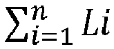
 la détermination, par le contrôleur de réseau à partir de la variable aléatoire de latence de trajet de transmission actif
- Procédé selon l'une quelconque des revendications 1 à 3, dans lequel le calcul, par le contrôleur de réseau, d'une latence de trajet de transmission de réserve sur la base des m secondes latences de nœud sur le trajet de transmission de réserve qui sont obtenues dans la période prédéfinie comprend :le calcul, par le contrôleur de réseau sur la base d'une seconde latence de nœud qui est d'un j ème dispositif de nœud de réseau sur le trajet de transmission de réserve et qui est obtenue dans la période prédéfinie, d'une seconde variable aléatoire de latence de trajet Lj du j ème dispositif de nœud de réseau, dans lequel une valeur de j est un entier positif allant de 1 à m, Lj comprend une seconde distribution de probabilité d'une latence de dispositif du paquet de détection circulant à travers le j ème dispositif de nœud de réseau sur le trajet de transmission de réserve dans la période prédéfinie, et la seconde distribution de probabilité est décalée d'une latence de liaison du j ème dispositif de nœud de réseau ;la détermination, par le contrôleur de réseau, d'une variable aléatoire de latence de trajet de transmission de réserve
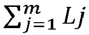
 la détermination, par le contrôleur de réseau à partir de la variable aléatoire de latence de trajet de transmission de réserve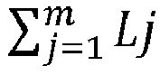
- Procédé selon l'une quelconque des revendications 1 à 4, dans lequel avant la détermination, par le contrôleur de réseau, que la latence de trajet de transmission actif est supérieure à un seuil de commutation, le procédé comprend en outre :lors de la détermination que la latence de trajet de transmission actif n'est pas supérieure à un seuil d'alarme, le retour, par le contrôleur de réseau, à l'exécution de l'obtention de n premières latences de nœud de n dispositifs de nœud de réseau sur un trajet de transmission actif à surveiller et l'obtention de m secondes latences de nœud de m dispositifs de nœud de réseau sur un trajet de transmission de réserve à surveiller ; etlors de la détermination que la latence de trajet de transmission actif est supérieure au seuil d'alarme, le fait de déterminer, par le contrôleur de réseau, si la latence de trajet de transmission actif est supérieure au seuil de commutation.
- Procédé selon l'une quelconque des revendications 1 à 5, comprenant en outre :lors de la détermination que la latence de trajet de transmission actif n'est pas supérieure au seuil de commutation, la génération, par le contrôleur de réseau, de secondes informations d'alarme du trajet de transmission actif, et la réinitialisation du compte dans le compteur de seuil de commutation, dans lequel une priorité d'alarme des secondes informations d'alarme est inférieure à une priorité d'alarme des premières informations d'alarme ; etle retour à l'exécution de l'obtention des n premières latences de nœud de n dispositifs de nœud de réseau sur un trajet de transmission actif à surveiller et l'obtention de m secondes latences de nœud de m dispositifs de nœud de réseau sur un trajet de transmission de réserve à surveiller.
- Procédé selon l'une quelconque des revendications 1 à 5, dans lequel après la détermination, par le contrôleur de réseau, que le compte dans le compteur de seuil de commutation est supérieur à un compte prédéfini, et avant de déterminer si la latence de trajet de transmission de réserve est inférieure au seuil de commutation, le procédé comprend en outre :lors de la détermination que la latence de trajet de transmission de réserve est inférieure au seuil d'alarme, l'exécution, par le contrôleur de réseau, de l'étape permettant de déterminer si la latence de trajet de transmission de réserve est inférieure au seuil de commutation ; etlors de la détermination que la latence de trajet de transmission de réserve n'est pas inférieure au seuil d'alarme, la génération, par le contrôleur de réseau, des premières informations d'alarme du trajet de transmission actif et des premières informations d'alarme du trajet de transmission de réserve.
- Procédé selon l'une quelconque des revendications 1 à 7, dans lequel après la commutation du paquet du trajet de transmission actif au trajet de transmission de réserve pour la transmission, le procédé comprend en outre :
la réinitialisation, par le contrôleur de réseau, du compte dans le compteur de seuil de commutation. - Contrôleur de réseau, comprenant une mémoire (801) et un processeur (802) et une interface réseau (803) qui communiquent avec la mémoire, dans lequel la mémoire est configurée pour stocker un code de programme pour la commande de trajet de transmission, dans lequel le code de programme comprend un ensemble d'instructions qui, lorsqu'elles sont exécutées par le processeur, amènent le contrôleur de réseau à :exécuter de manière itérative les étapes suivantes :l'obtention de n premières latences de nœud de n dispositifs de nœud de réseau sur un trajet de transmission actif à surveiller, et l'obtention (S302) de m secondes latences de nœud de m dispositifs de nœud de réseau sur un trajet de transmission de réserve à surveiller, dans lequel la première latence de nœud est la somme d'une latence de dispositif d'un premier dispositif de nœud de réseau sur le trajet de transmission actif et d'une latence d'une liaison entre le premier dispositif de nœud de réseau et un dispositif de nœud de réseau suivant, la seconde latence de nœud est la somme d'une latence de dispositif d'un second dispositif de nœud de réseau sur le trajet de transmission de réserve et d'une latence d'une liaison entre le second dispositif de nœud de réseau et un dispositif de nœud de réseau suivant, les n dispositifs de nœud de réseau comprennent le premier dispositif de nœud de réseau, les m dispositifs de nœud de réseau comprennent le second dispositif de nœud de réseau, n est supérieur ou égal à 2, et m est supérieur ou égal à 2 ;le calcul d'une latence de trajet de transmission actif sur la base des n premières latences de nœud sur le trajet de transmission actif qui sont obtenues dans une période prédéfinie, dans lequel la latence de trajet de transmission actif est utilisée pour indiquer une latence atteignant la première fiabilité de latence cible lorsque tous les paquets compris dans un flux de données de service sont transmis, et la première fiabilité de latence cible est utilisée pour indiquer un taux de réussite auquel un paquet dans le flux de données de service est transmis du premier dispositif de nœud de réseau au dernier dispositif de nœud de réseau sur le trajet de transmission actif ; etle calcul d'une latence de trajet de transmission de réserve sur la base des m secondes latences de nœud sur le trajet de transmission de réserve qui sont obtenues dans la période prédéfinie, dans lequel la latence de trajet de transmission de réserve est utilisée pour indiquer une latence atteignant une seconde fiabilité de latence cible lorsqu'un paquet de détection est transmis, et la seconde fiabilité de latence cible est utilisée pour indiquer un taux de réussite auquel le paquet de détection est transmis du premier dispositif de nœud de réseau au dernier dispositif de nœud de réseau sur le trajet de transmission de réserve ;jusqu'à ce que la latence de trajet de transmission actif soit déterminée comme étant supérieure à un seuil de commutation ; etlors de la détermination que la latence de trajet de transmission actif est supérieure à un seuil de commutation et que la latence de trajet de transmission de réserve est inférieure au seuil de commutation, la génération d'une commande de commutation du trajet actif au trajet de réserve ; etla commutation du paquet du trajet de transmission actif au trajet de transmission de réserve pour une transmission sur la base de la commande de commutation du trajet actif au trajet de réserve ;dans lequel après avoir déterminé que la latence de trajet de transmission actif est supérieure à un seuil de commutation, le contrôleur de réseau est en outre amené à exécuter les étapes suivantes :l'augmentation d'un compte dans un compteur de seuil de commutation de 1 ;lors de la détermination que le compte dans le compteur de seuil de commutation est supérieur à un compte prédéfini, le fait de déterminer si la latence de trajet de transmission de réserve est inférieure au seuil de commutation ; etlors de la détermination que le compte dans le compteur de seuil de commutation n'est pas supérieur au compte prédéfini, la génération de premières informations d'alarme du trajet de transmission actif, et le retour à l'exécution de l'obtention des n premières latences de nœud de n dispositifs de nœud de réseau sur un trajet de transmission actif à surveiller et l'obtention de m secondes latences de nœud de m dispositifs de nœud de réseau sur un trajet de transmission de réserve à surveiller.
- Dispositif de réseau selon la revendication 9, dans lequella latence de dispositif dans la première latence de nœud obtenue par le contrôleur de réseau est obtenue par mesure dans la période prédéfinie par un premier module de mesure de latence disposé sur le premier dispositif de nœud de réseau sur le trajet de transmission actif ; etla latence de dispositif dans le seconde latence de nœud obtenue par le contrôleur de réseau est obtenue par mesure dans la période prédéfinie par un second module de mesure de latence disposé sur le second dispositif de nœud de réseau sur le trajet de transmission de réserve.
- Contrôleur de réseau selon la revendication 9 ou 10, dans lequel le calcul, d'une latence de trajet de transmission actif sur la base des n premières latences de nœud sur le trajet de transmission actif qui sont obtenues dans une période prédéfinie comprend spécifiquement :le calcul, sur la base d'une première latence de nœud qui est d'un ième dispositif de nœud de réseau sur le trajet de transmission actif et qui est obtenue dans la période prédéfinie, d'une première variable aléatoire de latence de trajet Li du ième dispositif de nœud de réseau, dans lequel une valeur de i est un nombre entier positif allant de 1 à n, Li comprend une première distribution de probabilité de latences de dispositif de tous les paquets compris dans le flux de données qui circulent à travers le i ème dispositif de nœud de réseau sur le trajet de transmission actif dans la période prédéfinie, et la première distribution de probabilité est décalée d'une latence de liaison du i ème dispositif de nœud de réseau ;la détermination d'une variable aléatoire de latence de trajet de transmission actif

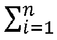 la détermination, par le contrôleur de réseau à partir de la variable aléatoire de latence de trajet de transmission actif
- Contrôleur de réseau selon l'une quelconque des revendications 9 à 11, dans lequel le calcul d'une latence de trajet de transmission de réserve sur la base des m secondes latences de nœud sur le trajet de transmission de réserve qui sont obtenues dans la période prédéfinie comprend :le calcul, sur la base d'une seconde latence de nœud qui est d'un j ème dispositif de nœud de réseau sur le trajet de transmission de réserve et qui est obtenue dans la période prédéfinie, d'une seconde variable aléatoire de latence de trajet Lj du j ème dispositif de nœud de réseau, dans lequel une valeur de j est un nombre entier positif allant de 1 à m, Lj comprend une seconde distribution de probabilité d'une latence de dispositif du paquet de détection circulant à travers le j ème dispositif de nœud de réseau sur le trajet de transmission de réserve dans la période prédéfinie, et la seconde distribution de probabilité est décalée d'une latence de liaison du j ème dispositif de nœud de réseau ;la détermination d'une variable aléatoire de latence de trajet de transmission de réserve

 la détermination, à partir de la variable aléatoire de latence de trajet de transmission de réserve
- Contrôleur de réseau selon l'une quelconque des revendications 9 à 12, dans lequel avant de déterminer que la latence de trajet de transmission actif est supérieure à un seuil de commutation, le contrôleur de réseau est en outre amené à exécuter les étapes suivantes :lors de la détermination que la latence de trajet de transmission actif n'est pas supérieure à un seuil d'alarme, le retour à l'exécution de l'obtention de n premières latences de nœud de n dispositifs de nœud de réseau sur un trajet de transmission actif à surveiller et l'obtention de m secondes latences de nœud de m dispositifs de nœud de réseau sur un trajet de transmission de réserve à surveiller ; etlors de la détermination que la latence de trajet de transmission actif est supérieure au seuil d'alarme, le fait de déterminer si la latence de trajet de transmission actif est supérieure au seuil de commutation.
- Contrôleur de réseau selon l'une quelconque des revendications 9 à 13, le contrôleur de réseau est en outre amené à exécuter les étapes suivantes : dans lequel lors de la détermination que la latence de trajet de transmission actif n'est pas supérieure au seuil de commutation, la génération de secondes informations d'alarme du trajet de transmission actif, et la réinitialisation du compte dans le compteur de seuil de commutation, dans lequel une priorité d'alarme des secondes informations d'alarme est inférieure à une priorité d'alarme des premières informations d'alarme ; et
le retour à l'exécution de l'obtention des n premières latences de nœud de n dispositifs de nœud de réseau sur un trajet de transmission actif à surveiller et l'obtention de m secondes latences de nœud de m dispositifs de nœud de réseau sur un trajet de transmission de réserve à surveiller. - Contrôleur de réseau selon l'une quelconque des revendications 9 à 13, dans lequel après avoir déterminé que le compte dans le compteur de seuil de commutation est supérieur à un compte prédéfini, et avant de déterminer si la latence de trajet de transmission de réserve est inférieure au seuil de commutation, le contrôleur de réseau est en outre amené à exécuter les étapes suivantes :lors de la détermination que la latence de trajet de transmission de réserve est inférieure au seuil d'alarme, l'exécution de l'étape permettant de déterminer si la latence de trajet de transmission de réserve est inférieure au seuil de commutation ; etlors de la détermination que la latence de trajet de transmission de réserve n'est pas inférieure au seuil d'alarme, la génération des premières informations d'alarme du trajet de transmission actif et des premières informations d'alarme du trajet de transmission de réserve.
Applications Claiming Priority (2)
| Application Number | Priority Date | Filing Date | Title |
|---|---|---|---|
| CN201710724352.5A CN109428742B (zh) | 2017-08-22 | 2017-08-22 | 基于时延传输路径控制方法、网络控制器和系统 |
| PCT/CN2018/075612 WO2019037394A1 (fr) | 2017-08-22 | 2018-02-07 | Procédé, contrôleur de réseau et système de commande de trajet de transmission basée sur le retard |
Publications (3)
| Publication Number | Publication Date |
|---|---|
| EP3661133A1 EP3661133A1 (fr) | 2020-06-03 |
| EP3661133A4 EP3661133A4 (fr) | 2020-07-22 |
| EP3661133B1 true EP3661133B1 (fr) | 2022-01-26 |
Family
ID=65439316
Family Applications (1)
| Application Number | Title | Priority Date | Filing Date |
|---|---|---|---|
| EP18848620.3A Not-in-force EP3661133B1 (fr) | 2017-08-22 | 2018-02-07 | Procédé, contrôleur de réseau et système de commande de trajet de transmission basée sur le retard |
Country Status (6)
| Country | Link |
|---|---|
| US (1) | US11245605B2 (fr) |
| EP (1) | EP3661133B1 (fr) |
| JP (1) | JP6991313B2 (fr) |
| KR (1) | KR102348987B1 (fr) |
| CN (1) | CN109428742B (fr) |
| WO (1) | WO2019037394A1 (fr) |
Families Citing this family (25)
| Publication number | Priority date | Publication date | Assignee | Title |
|---|---|---|---|---|
| CN109428742B (zh) * | 2017-08-22 | 2020-12-15 | 华为技术有限公司 | 基于时延传输路径控制方法、网络控制器和系统 |
| JP7322951B2 (ja) * | 2019-07-01 | 2023-08-08 | 日本電信電話株式会社 | 経路制御装置、経路制御方法、プログラム、および、ネットワークシステム |
| JP7314728B2 (ja) * | 2019-09-09 | 2023-07-26 | 株式会社明電舎 | 通信経路の切替方式、通信経路の切替方法 |
| US11240163B2 (en) * | 2020-01-17 | 2022-02-01 | Vmware, Inc. | Practical overlay network latency measurement in datacenter |
| US11283699B2 (en) | 2020-01-17 | 2022-03-22 | Vmware, Inc. | Practical overlay network latency measurement in datacenter |
| CN111740874B (zh) * | 2020-05-21 | 2021-12-07 | 中国汽车技术研究中心有限公司 | 智能驾驶汽车软件架构通信链的功能安全监控装置及方法 |
| WO2022000234A1 (fr) * | 2020-06-30 | 2022-01-06 | 华为技术有限公司 | Procédé de communication et appareil associé |
| US11570090B2 (en) | 2020-07-29 | 2023-01-31 | Vmware, Inc. | Flow tracing operation in container cluster |
| US11336533B1 (en) | 2021-01-08 | 2022-05-17 | Vmware, Inc. | Network visualization of correlations between logical elements and associated physical elements |
| CN112929276B (zh) * | 2021-01-25 | 2022-07-08 | 中国联合网络通信集团有限公司 | 一种路径调整方法、装置及系统 |
| CN112954765B (zh) * | 2021-02-24 | 2022-12-09 | 四川速宝网络科技有限公司 | 一种基于网络状态监控的动态算子选路方法 |
| CN112988313B (zh) * | 2021-05-13 | 2021-09-14 | 金锐同创(北京)科技股份有限公司 | 路径确定方法、装置及电子设备 |
| US11855862B2 (en) | 2021-09-17 | 2023-12-26 | Vmware, Inc. | Tagging packets for monitoring and analysis |
| CN116133004B (zh) * | 2021-11-12 | 2026-03-20 | 中国移动通信有限公司研究院 | 链路检测方法、装置、网络设备及网元节点 |
| CN116647484A (zh) * | 2022-02-16 | 2023-08-25 | 中兴通讯股份有限公司 | 报文调度方法、网络设备及计算机可读存储介质 |
| US12407592B2 (en) * | 2022-02-24 | 2025-09-02 | Arris Enterprises Llc | R-PHY map advance time selection |
| EP4503554A4 (fr) | 2022-03-30 | 2025-04-30 | Rakuten Mobile, Inc. | Système de détermination de trajet de communication et procédé de détermination de trajet de communication |
| WO2023188187A1 (fr) * | 2022-03-30 | 2023-10-05 | 楽天モバイル株式会社 | Système de détermination de trajet de communication et procédé de détermination de trajet de communication |
| CN118200199A (zh) * | 2022-12-14 | 2024-06-14 | 华为技术有限公司 | 时延确定方法、装置和智能驾驶设备 |
| CN116155802B (zh) * | 2023-01-28 | 2025-07-08 | 广东云下汇金科技有限公司 | 一种自动路由优化方法及装置 |
| CN116846819B (zh) * | 2023-07-03 | 2026-07-21 | 武汉烽火技术服务有限公司 | 一种传输网数据业务的保护倒换方法及相应的装置 |
| CN117253492B (zh) * | 2023-11-17 | 2024-04-02 | 深圳超然科技股份有限公司 | 基于声纹识别的遥控方法、装置、智能电器系统、介质 |
| CN119135269B (zh) * | 2024-11-13 | 2025-01-28 | 合肥焕智科技有限公司 | 一种基于光信号通讯的控制系统 |
| CN119341974B (zh) * | 2024-12-16 | 2025-03-28 | 深圳市中一致远科技集团有限公司 | 一种司法鉴定信息的数据远程传输系统 |
| CN120342913A (zh) * | 2025-06-16 | 2025-07-18 | 中国人民解放军海军工程大学 | 故障注入场景下的延迟监测与同步调整方法及系统 |
Family Cites Families (25)
| Publication number | Priority date | Publication date | Assignee | Title |
|---|---|---|---|---|
| JP4302290B2 (ja) * | 2000-05-15 | 2009-07-22 | 三菱電機株式会社 | データ伝送制御システム |
| US8223634B2 (en) * | 2004-02-18 | 2012-07-17 | Fortinet, Inc. | Mechanism for implementing load balancing in a network |
| CN100488070C (zh) * | 2005-08-17 | 2009-05-13 | 上海华为技术有限公司 | 通信系统中链路切换装置及其方法 |
| US8072879B2 (en) * | 2006-02-03 | 2011-12-06 | Cisco Technology, Inc. | Technique for determining whether to reestablish fast rerouted primary tunnels based on backup tunnel path quality feedback |
| JP2008131346A (ja) * | 2006-11-21 | 2008-06-05 | Oki Electric Ind Co Ltd | Ipネットワークシステム |
| US7948897B2 (en) * | 2007-08-15 | 2011-05-24 | Adc Telecommunications, Inc. | Delay management for distributed communications networks |
| US7907520B2 (en) * | 2007-09-27 | 2011-03-15 | Verizon Patent And Licensing Inc. | Path testing and switching |
| JP4644845B2 (ja) * | 2007-10-01 | 2011-03-09 | Necインフロンティア株式会社 | 通信装置、経路選択方法及びプログラム |
| CN101159669A (zh) * | 2007-10-09 | 2008-04-09 | 华为技术有限公司 | 一种业务流量切换方法及装置 |
| CN101577661B (zh) | 2008-05-09 | 2013-09-11 | 华为技术有限公司 | 一种路径切换的方法和设备 |
| US10785117B2 (en) * | 2009-06-11 | 2020-09-22 | Talari Networks Incorporated | Methods and apparatus for configuring a standby WAN link in an adaptive private network |
| US9063825B1 (en) | 2009-09-21 | 2015-06-23 | Tilera Corporation | Memory controller load balancing with configurable striping domains |
| JP2011151752A (ja) * | 2010-01-25 | 2011-08-04 | Fujitsu Ltd | パケットトランスポート障害検出機能を含む通信ネットワークシステム |
| CN102447980B (zh) * | 2010-09-30 | 2015-01-28 | 中兴通讯股份有限公司 | 一种路由控制方法、系统及路由计算装置 |
| JP5784139B2 (ja) * | 2011-11-01 | 2015-09-24 | 株式会社日立製作所 | 通信システム |
| CN102412955B (zh) * | 2011-11-28 | 2015-08-19 | 华为技术有限公司 | 光纤不对称时主从设备间的时间偏差获取方法和通信系统 |
| CN102801606B (zh) * | 2012-02-24 | 2015-09-02 | 华北电力大学 | 一种sctp主路径自动切换方法 |
| JP5958056B2 (ja) * | 2012-05-02 | 2016-07-27 | 富士通株式会社 | 障害救済方法及びノード装置 |
| JP5678123B2 (ja) * | 2013-04-22 | 2015-02-25 | エヌ・ティ・ティ・コミュニケーションズ株式会社 | 伝送装置、伝送路切り替え方法、及びプログラム |
| JP6102461B2 (ja) * | 2013-04-23 | 2017-03-29 | 富士通株式会社 | 通信装置、マルチホップ無線通信ネットワークシステム及び通信方法 |
| CN105323807B (zh) * | 2014-08-01 | 2019-01-25 | 电信科学技术研究院 | 一种进行切换的方法和设备 |
| US10218629B1 (en) * | 2014-12-23 | 2019-02-26 | Juniper Networks, Inc. | Moving packet flows between network paths |
| CN106713141B (zh) * | 2015-11-18 | 2020-04-28 | 华为技术有限公司 | 用于获得目标传输路径的方法和网络节点 |
| US10333855B2 (en) * | 2017-04-19 | 2019-06-25 | Cisco Technology, Inc. | Latency reduction in service function paths |
| CN109428742B (zh) * | 2017-08-22 | 2020-12-15 | 华为技术有限公司 | 基于时延传输路径控制方法、网络控制器和系统 |
-
2017
- 2017-08-22 CN CN201710724352.5A patent/CN109428742B/zh not_active Expired - Fee Related
-
2018
- 2018-02-07 JP JP2020511208A patent/JP6991313B2/ja not_active Expired - Fee Related
- 2018-02-07 KR KR1020207007809A patent/KR102348987B1/ko not_active Expired - Fee Related
- 2018-02-07 WO PCT/CN2018/075612 patent/WO2019037394A1/fr not_active Ceased
- 2018-02-07 EP EP18848620.3A patent/EP3661133B1/fr not_active Not-in-force
-
2020
- 2020-02-19 US US16/795,108 patent/US11245605B2/en not_active Expired - Fee Related
Also Published As
| Publication number | Publication date |
|---|---|
| JP2020532216A (ja) | 2020-11-05 |
| CN109428742A (zh) | 2019-03-05 |
| EP3661133A1 (fr) | 2020-06-03 |
| KR102348987B1 (ko) | 2022-01-07 |
| US11245605B2 (en) | 2022-02-08 |
| KR20200038526A (ko) | 2020-04-13 |
| WO2019037394A1 (fr) | 2019-02-28 |
| US20200186453A1 (en) | 2020-06-11 |
| CN109428742B (zh) | 2020-12-15 |
| EP3661133A4 (fr) | 2020-07-22 |
| JP6991313B2 (ja) | 2022-01-12 |
Similar Documents
| Publication | Publication Date | Title |
|---|---|---|
| US11245605B2 (en) | Latency-based transmission path control method, network controller, and system | |
| US12058010B2 (en) | Adaptive stress testing of SD-WAN tunnels for what-if scenario model training | |
| US9106548B2 (en) | Network fault localization | |
| US9992117B2 (en) | Network apparatus, communication system, abnormal traffic detection method, and program | |
| US10033592B2 (en) | Method and system for monitoring network link and storage medium therefor | |
| CN104506482A (zh) | 网络攻击检测方法及装置 | |
| US20160301599A1 (en) | Method and first network node for managing a first ip path used by a connection | |
| EP3295612B1 (fr) | Gestion de performances de liaison montante | |
| WO2017084487A1 (fr) | Procédé d'obtention de trajet de transmission cible et nœud de réseau | |
| EP3694150B1 (fr) | Procédé, dispositif et système de détection de défaillance de liaison | |
| US20130215939A1 (en) | Method, apparatus and system for setting a size of an event correlation time window | |
| US11606282B2 (en) | Method and device for detecting network reliability | |
| CN108141406A (zh) | 一种业务故障处理的方法、装置及设备 | |
| CN107623607B (zh) | Bfd会话连接建立方法及装置 | |
| US10462032B2 (en) | Probing a network | |
| KR20150100027A (ko) | 소프트웨어 정의 네트워크에서 라우팅 설정 방법 및 장치 | |
| Orzen et al. | Internet Time as Virtual Time for Real-Time Session Routing | |
| CN114363160B (zh) | 基于广域网的网络管理方法及装置 | |
| CN110493141A (zh) | 一种路由转发传输控制方法、装置、设备和存储介质 | |
| CN121462385A (zh) | 一种路径故障的处理方法、装置、设备、介质及产品 | |
| Bohacek et al. | Models and Techniques for Network Tomography | |
| JP2009171453A (ja) | 送信ノード、タイトリンク特定方法およびタイトリンク特定プログラム | |
| Kumar et al. | Identification of Packet Losses in TCP Over Wired Wireless Networks | |
| Bohacek et al. | Network tomography | |
| Dong | Available Bandwidth Measurement Method of High-Speed Network Based on Link Idle Probability |
Legal Events
| Date | Code | Title | Description |
|---|---|---|---|
| STAA | Information on the status of an ep patent application or granted ep patent |
Free format text: STATUS: THE INTERNATIONAL PUBLICATION HAS BEEN MADE |
|
| PUAI | Public reference made under article 153(3) epc to a published international application that has entered the european phase |
Free format text: ORIGINAL CODE: 0009012 |
|
| STAA | Information on the status of an ep patent application or granted ep patent |
Free format text: STATUS: REQUEST FOR EXAMINATION WAS MADE |
|
| 17P | Request for examination filed |
Effective date: 20200225 |
|
| AK | Designated contracting states |
Kind code of ref document: A1 Designated state(s): AL AT BE BG CH CY CZ DE DK EE ES FI FR GB GR HR HU IE IS IT LI LT LU LV MC MK MT NL NO PL PT RO RS SE SI SK SM TR |
|
| AX | Request for extension of the european patent |
Extension state: BA ME |
|
| A4 | Supplementary search report drawn up and despatched |
Effective date: 20200619 |
|
| RIC1 | Information provided on ipc code assigned before grant |
Ipc: H04L 12/727 20130101ALI20200615BHEP Ipc: H04L 12/707 20130101AFI20200615BHEP |
|
| DAV | Request for validation of the european patent (deleted) | ||
| DAX | Request for extension of the european patent (deleted) | ||
| STAA | Information on the status of an ep patent application or granted ep patent |
Free format text: STATUS: EXAMINATION IS IN PROGRESS |
|
| 17Q | First examination report despatched |
Effective date: 20210430 |
|
| GRAP | Despatch of communication of intention to grant a patent |
Free format text: ORIGINAL CODE: EPIDOSNIGR1 |
|
| STAA | Information on the status of an ep patent application or granted ep patent |
Free format text: STATUS: GRANT OF PATENT IS INTENDED |
|
| INTG | Intention to grant announced |
Effective date: 20210929 |
|
| GRAS | Grant fee paid |
Free format text: ORIGINAL CODE: EPIDOSNIGR3 |
|
| GRAA | (expected) grant |
Free format text: ORIGINAL CODE: 0009210 |
|
| STAA | Information on the status of an ep patent application or granted ep patent |
Free format text: STATUS: THE PATENT HAS BEEN GRANTED |
|
| AK | Designated contracting states |
Kind code of ref document: B1 Designated state(s): AL AT BE BG CH CY CZ DE DK EE ES FI FR GB GR HR HU IE IS IT LI LT LU LV MC MK MT NL NO PL PT RO RS SE SI SK SM TR |
|
| REG | Reference to a national code |
Ref country code: GB Ref legal event code: FG4D |
|
| REG | Reference to a national code |
Ref country code: CH Ref legal event code: EP |
|
| REG | Reference to a national code |
Ref country code: AT Ref legal event code: REF Ref document number: 1466159 Country of ref document: AT Kind code of ref document: T Effective date: 20220215 |
|
| REG | Reference to a national code |
Ref country code: IE Ref legal event code: FG4D |
|
| REG | Reference to a national code |
Ref country code: DE Ref legal event code: R096 Ref document number: 602018030282 Country of ref document: DE |
|
| REG | Reference to a national code |
Ref country code: LT Ref legal event code: MG9D |
|
| REG | Reference to a national code |
Ref country code: NL Ref legal event code: MP Effective date: 20220126 |
|
| REG | Reference to a national code |
Ref country code: AT Ref legal event code: MK05 Ref document number: 1466159 Country of ref document: AT Kind code of ref document: T Effective date: 20220126 |
|
| PG25 | Lapsed in a contracting state [announced via postgrant information from national office to epo] |
Ref country code: NL Free format text: LAPSE BECAUSE OF FAILURE TO SUBMIT A TRANSLATION OF THE DESCRIPTION OR TO PAY THE FEE WITHIN THE PRESCRIBED TIME-LIMIT Effective date: 20220126 |
|
| PG25 | Lapsed in a contracting state [announced via postgrant information from national office to epo] |
Ref country code: SE Free format text: LAPSE BECAUSE OF FAILURE TO SUBMIT A TRANSLATION OF THE DESCRIPTION OR TO PAY THE FEE WITHIN THE PRESCRIBED TIME-LIMIT Effective date: 20220126 Ref country code: RS Free format text: LAPSE BECAUSE OF FAILURE TO SUBMIT A TRANSLATION OF THE DESCRIPTION OR TO PAY THE FEE WITHIN THE PRESCRIBED TIME-LIMIT Effective date: 20220126 Ref country code: PT Free format text: LAPSE BECAUSE OF FAILURE TO SUBMIT A TRANSLATION OF THE DESCRIPTION OR TO PAY THE FEE WITHIN THE PRESCRIBED TIME-LIMIT Effective date: 20220526 Ref country code: NO Free format text: LAPSE BECAUSE OF FAILURE TO SUBMIT A TRANSLATION OF THE DESCRIPTION OR TO PAY THE FEE WITHIN THE PRESCRIBED TIME-LIMIT Effective date: 20220426 Ref country code: LT Free format text: LAPSE BECAUSE OF FAILURE TO SUBMIT A TRANSLATION OF THE DESCRIPTION OR TO PAY THE FEE WITHIN THE PRESCRIBED TIME-LIMIT Effective date: 20220126 Ref country code: HR Free format text: LAPSE BECAUSE OF FAILURE TO SUBMIT A TRANSLATION OF THE DESCRIPTION OR TO PAY THE FEE WITHIN THE PRESCRIBED TIME-LIMIT Effective date: 20220126 Ref country code: ES Free format text: LAPSE BECAUSE OF FAILURE TO SUBMIT A TRANSLATION OF THE DESCRIPTION OR TO PAY THE FEE WITHIN THE PRESCRIBED TIME-LIMIT Effective date: 20220126 Ref country code: BG Free format text: LAPSE BECAUSE OF FAILURE TO SUBMIT A TRANSLATION OF THE DESCRIPTION OR TO PAY THE FEE WITHIN THE PRESCRIBED TIME-LIMIT Effective date: 20220426 |
|
| PG25 | Lapsed in a contracting state [announced via postgrant information from national office to epo] |
Ref country code: PL Free format text: LAPSE BECAUSE OF FAILURE TO SUBMIT A TRANSLATION OF THE DESCRIPTION OR TO PAY THE FEE WITHIN THE PRESCRIBED TIME-LIMIT Effective date: 20220126 Ref country code: LV Free format text: LAPSE BECAUSE OF FAILURE TO SUBMIT A TRANSLATION OF THE DESCRIPTION OR TO PAY THE FEE WITHIN THE PRESCRIBED TIME-LIMIT Effective date: 20220126 Ref country code: GR Free format text: LAPSE BECAUSE OF FAILURE TO SUBMIT A TRANSLATION OF THE DESCRIPTION OR TO PAY THE FEE WITHIN THE PRESCRIBED TIME-LIMIT Effective date: 20220427 Ref country code: FI Free format text: LAPSE BECAUSE OF FAILURE TO SUBMIT A TRANSLATION OF THE DESCRIPTION OR TO PAY THE FEE WITHIN THE PRESCRIBED TIME-LIMIT Effective date: 20220126 Ref country code: AT Free format text: LAPSE BECAUSE OF FAILURE TO SUBMIT A TRANSLATION OF THE DESCRIPTION OR TO PAY THE FEE WITHIN THE PRESCRIBED TIME-LIMIT Effective date: 20220126 |
|
| PG25 | Lapsed in a contracting state [announced via postgrant information from national office to epo] |
Ref country code: IS Free format text: LAPSE BECAUSE OF FAILURE TO SUBMIT A TRANSLATION OF THE DESCRIPTION OR TO PAY THE FEE WITHIN THE PRESCRIBED TIME-LIMIT Effective date: 20220526 |
|
| REG | Reference to a national code |
Ref country code: CH Ref legal event code: PL |
|
| REG | Reference to a national code |
Ref country code: BE Ref legal event code: MM Effective date: 20220228 |
|
| REG | Reference to a national code |
Ref country code: DE Ref legal event code: R097 Ref document number: 602018030282 Country of ref document: DE |
|
| PG25 | Lapsed in a contracting state [announced via postgrant information from national office to epo] |
Ref country code: SM Free format text: LAPSE BECAUSE OF FAILURE TO SUBMIT A TRANSLATION OF THE DESCRIPTION OR TO PAY THE FEE WITHIN THE PRESCRIBED TIME-LIMIT Effective date: 20220126 Ref country code: SK Free format text: LAPSE BECAUSE OF FAILURE TO SUBMIT A TRANSLATION OF THE DESCRIPTION OR TO PAY THE FEE WITHIN THE PRESCRIBED TIME-LIMIT Effective date: 20220126 Ref country code: RO Free format text: LAPSE BECAUSE OF FAILURE TO SUBMIT A TRANSLATION OF THE DESCRIPTION OR TO PAY THE FEE WITHIN THE PRESCRIBED TIME-LIMIT Effective date: 20220126 Ref country code: MC Free format text: LAPSE BECAUSE OF FAILURE TO SUBMIT A TRANSLATION OF THE DESCRIPTION OR TO PAY THE FEE WITHIN THE PRESCRIBED TIME-LIMIT Effective date: 20220126 Ref country code: LU Free format text: LAPSE BECAUSE OF NON-PAYMENT OF DUE FEES Effective date: 20220207 Ref country code: EE Free format text: LAPSE BECAUSE OF FAILURE TO SUBMIT A TRANSLATION OF THE DESCRIPTION OR TO PAY THE FEE WITHIN THE PRESCRIBED TIME-LIMIT Effective date: 20220126 Ref country code: DK Free format text: LAPSE BECAUSE OF FAILURE TO SUBMIT A TRANSLATION OF THE DESCRIPTION OR TO PAY THE FEE WITHIN THE PRESCRIBED TIME-LIMIT Effective date: 20220126 Ref country code: CZ Free format text: LAPSE BECAUSE OF FAILURE TO SUBMIT A TRANSLATION OF THE DESCRIPTION OR TO PAY THE FEE WITHIN THE PRESCRIBED TIME-LIMIT Effective date: 20220126 |
|
| PG25 | Lapsed in a contracting state [announced via postgrant information from national office to epo] |
Ref country code: AL Free format text: LAPSE BECAUSE OF FAILURE TO SUBMIT A TRANSLATION OF THE DESCRIPTION OR TO PAY THE FEE WITHIN THE PRESCRIBED TIME-LIMIT Effective date: 20220126 |
|
| PLBE | No opposition filed within time limit |
Free format text: ORIGINAL CODE: 0009261 |
|
| STAA | Information on the status of an ep patent application or granted ep patent |
Free format text: STATUS: NO OPPOSITION FILED WITHIN TIME LIMIT |
|
| 26N | No opposition filed |
Effective date: 20221027 |
|
| PG25 | Lapsed in a contracting state [announced via postgrant information from national office to epo] |
Ref country code: LI Free format text: LAPSE BECAUSE OF NON-PAYMENT OF DUE FEES Effective date: 20220228 Ref country code: IE Free format text: LAPSE BECAUSE OF NON-PAYMENT OF DUE FEES Effective date: 20220207 Ref country code: FR Free format text: LAPSE BECAUSE OF NON-PAYMENT OF DUE FEES Effective date: 20220326 Ref country code: CH Free format text: LAPSE BECAUSE OF NON-PAYMENT OF DUE FEES Effective date: 20220228 |
|
| PGFP | Annual fee paid to national office [announced via postgrant information from national office to epo] |
Ref country code: GB Payment date: 20221230 Year of fee payment: 6 |
|
| PG25 | Lapsed in a contracting state [announced via postgrant information from national office to epo] |
Ref country code: SI Free format text: LAPSE BECAUSE OF FAILURE TO SUBMIT A TRANSLATION OF THE DESCRIPTION OR TO PAY THE FEE WITHIN THE PRESCRIBED TIME-LIMIT Effective date: 20220126 Ref country code: BE Free format text: LAPSE BECAUSE OF NON-PAYMENT OF DUE FEES Effective date: 20220228 |
|
| PGFP | Annual fee paid to national office [announced via postgrant information from national office to epo] |
Ref country code: DE Payment date: 20221230 Year of fee payment: 6 |
|
| PG25 | Lapsed in a contracting state [announced via postgrant information from national office to epo] |
Ref country code: IT Free format text: LAPSE BECAUSE OF FAILURE TO SUBMIT A TRANSLATION OF THE DESCRIPTION OR TO PAY THE FEE WITHIN THE PRESCRIBED TIME-LIMIT Effective date: 20220126 |
|
| PG25 | Lapsed in a contracting state [announced via postgrant information from national office to epo] |
Ref country code: MK Free format text: LAPSE BECAUSE OF FAILURE TO SUBMIT A TRANSLATION OF THE DESCRIPTION OR TO PAY THE FEE WITHIN THE PRESCRIBED TIME-LIMIT Effective date: 20220126 Ref country code: CY Free format text: LAPSE BECAUSE OF FAILURE TO SUBMIT A TRANSLATION OF THE DESCRIPTION OR TO PAY THE FEE WITHIN THE PRESCRIBED TIME-LIMIT Effective date: 20220126 |
|
| PG25 | Lapsed in a contracting state [announced via postgrant information from national office to epo] |
Ref country code: HU Free format text: LAPSE BECAUSE OF FAILURE TO SUBMIT A TRANSLATION OF THE DESCRIPTION OR TO PAY THE FEE WITHIN THE PRESCRIBED TIME-LIMIT; INVALID AB INITIO Effective date: 20180207 |
|
| REG | Reference to a national code |
Ref country code: DE Ref legal event code: R119 Ref document number: 602018030282 Country of ref document: DE |
|
| PG25 | Lapsed in a contracting state [announced via postgrant information from national office to epo] |
Ref country code: MT Free format text: LAPSE BECAUSE OF FAILURE TO SUBMIT A TRANSLATION OF THE DESCRIPTION OR TO PAY THE FEE WITHIN THE PRESCRIBED TIME-LIMIT Effective date: 20220126 |
|
| GBPC | Gb: european patent ceased through non-payment of renewal fee |
Effective date: 20240207 |
|
| PG25 | Lapsed in a contracting state [announced via postgrant information from national office to epo] |
Ref country code: DE Free format text: LAPSE BECAUSE OF NON-PAYMENT OF DUE FEES Effective date: 20240903 |
|
| PG25 | Lapsed in a contracting state [announced via postgrant information from national office to epo] |
Ref country code: GB Free format text: LAPSE BECAUSE OF NON-PAYMENT OF DUE FEES Effective date: 20240207 |
|
| PG25 | Lapsed in a contracting state [announced via postgrant information from national office to epo] |
Ref country code: GB Free format text: LAPSE BECAUSE OF NON-PAYMENT OF DUE FEES Effective date: 20240207 Ref country code: DE Free format text: LAPSE BECAUSE OF NON-PAYMENT OF DUE FEES Effective date: 20240903 |
|
| PG25 | Lapsed in a contracting state [announced via postgrant information from national office to epo] |
Ref country code: TR Free format text: LAPSE BECAUSE OF FAILURE TO SUBMIT A TRANSLATION OF THE DESCRIPTION OR TO PAY THE FEE WITHIN THE PRESCRIBED TIME-LIMIT Effective date: 20220126 |