EP3661175A1 - Übertragungsmodul, übertragungsmechanismus und mobiles endgerät - Google Patents
Übertragungsmodul, übertragungsmechanismus und mobiles endgerät Download PDFInfo
- Publication number
- EP3661175A1 EP3661175A1 EP19212532.6A EP19212532A EP3661175A1 EP 3661175 A1 EP3661175 A1 EP 3661175A1 EP 19212532 A EP19212532 A EP 19212532A EP 3661175 A1 EP3661175 A1 EP 3661175A1
- Authority
- EP
- European Patent Office
- Prior art keywords
- pushing member
- connecting portion
- mounting seat
- wedge block
- coupled
- Prior art date
- Legal status (The legal status is an assumption and is not a legal conclusion. Google has not performed a legal analysis and makes no representation as to the accuracy of the status listed.)
- Granted
Links
Images



Classifications
-
- H—ELECTRICITY
- H04—ELECTRIC COMMUNICATION TECHNIQUE
- H04M—TELEPHONIC COMMUNICATION
- H04M1/00—Substation equipment, e.g. for use by subscribers
- H04M1/02—Constructional features of telephone sets
- H04M1/0202—Portable telephone sets, e.g. cordless phones, mobile phones or bar type handsets
- H04M1/026—Details of the structure or mounting of specific components
- H04M1/0264—Details of the structure or mounting of specific components for a camera module assembly
-
- F—MECHANICAL ENGINEERING; LIGHTING; HEATING; WEAPONS; BLASTING
- F16—ENGINEERING ELEMENTS AND UNITS; GENERAL MEASURES FOR PRODUCING AND MAINTAINING EFFECTIVE FUNCTIONING OF MACHINES OR INSTALLATIONS; THERMAL INSULATION IN GENERAL
- F16M—FRAMES, CASINGS OR BEDS OF ENGINES, MACHINES OR APPARATUS, NOT SPECIFIC TO ENGINES, MACHINES OR APPARATUS PROVIDED FOR ELSEWHERE; STANDS; SUPPORTS
- F16M11/00—Stands or trestles as supports for apparatus or articles placed thereon ; Stands for scientific apparatus such as gravitational force meters
- F16M11/02—Heads
- F16M11/04—Means for attachment of apparatus; Means allowing adjustment of the apparatus relatively to the stand
- F16M11/06—Means for attachment of apparatus; Means allowing adjustment of the apparatus relatively to the stand allowing pivoting
- F16M11/10—Means for attachment of apparatus; Means allowing adjustment of the apparatus relatively to the stand allowing pivoting around a horizontal axis
- F16M11/105—Means for attachment of apparatus; Means allowing adjustment of the apparatus relatively to the stand allowing pivoting around a horizontal axis the horizontal axis being the roll axis, e.g. for creating a landscape-portrait rotation
-
- G—PHYSICS
- G06—COMPUTING OR CALCULATING; COUNTING
- G06F—ELECTRIC DIGITAL DATA PROCESSING
- G06F1/00—Details not covered by groups G06F3/00 - G06F13/00 and G06F21/00
- G06F1/16—Constructional details or arrangements
- G06F1/1613—Constructional details or arrangements for portable computers
- G06F1/1633—Constructional details or arrangements of portable computers not specific to the type of enclosures covered by groups G06F1/1615 - G06F1/1626
- G06F1/1675—Miscellaneous details related to the relative movement between the different enclosures or enclosure parts
- G06F1/1679—Miscellaneous details related to the relative movement between the different enclosures or enclosure parts for locking or maintaining the movable parts of the enclosure in a fixed position, e.g. latching mechanism at the edge of the display in a laptop or for the screen protective cover of a PDA
-
- G—PHYSICS
- G06—COMPUTING OR CALCULATING; COUNTING
- G06F—ELECTRIC DIGITAL DATA PROCESSING
- G06F1/00—Details not covered by groups G06F3/00 - G06F13/00 and G06F21/00
- G06F1/16—Constructional details or arrangements
- G06F1/1613—Constructional details or arrangements for portable computers
- G06F1/1633—Constructional details or arrangements of portable computers not specific to the type of enclosures covered by groups G06F1/1615 - G06F1/1626
- G06F1/1684—Constructional details or arrangements related to integrated I/O peripherals not covered by groups G06F1/1635 - G06F1/1675
- G06F1/1686—Constructional details or arrangements related to integrated I/O peripherals not covered by groups G06F1/1635 - G06F1/1675 the I/O peripheral being an integrated camera
-
- H—ELECTRICITY
- H04—ELECTRIC COMMUNICATION TECHNIQUE
- H04N—PICTORIAL COMMUNICATION, e.g. TELEVISION
- H04N23/00—Cameras or camera modules comprising electronic image sensors; Control thereof
- H04N23/50—Constructional details
- H04N23/51—Housings
-
- H—ELECTRICITY
- H04—ELECTRIC COMMUNICATION TECHNIQUE
- H04N—PICTORIAL COMMUNICATION, e.g. TELEVISION
- H04N23/00—Cameras or camera modules comprising electronic image sensors; Control thereof
- H04N23/57—Mechanical or electrical details of cameras or camera modules specially adapted for being embedded in other devices
-
- H—ELECTRICITY
- H04—ELECTRIC COMMUNICATION TECHNIQUE
- H04M—TELEPHONIC COMMUNICATION
- H04M2250/00—Details of telephonic subscriber devices
- H04M2250/20—Details of telephonic subscriber devices including a rotatable camera
Definitions
- the present disclosure relates to a technical field of mobile terminals.
- a general solution is to arrange a telescopic camera in a mobile terminal, and a shooting scenario of the telescopic camera is relatively undiversified.
- a mobile terminal which includes:
- a mobile terminal which includes a mounting seat, a driving member, a first pushing member and a second pushing member, wherein the first pushing member and the second pushing member are correspondingly coupled to the mounting seat; a cooperation between the driving member and the first pushing member enables the second pushing member to move and drive the first pushing member to move from a first position to a third position via a second position; between the first position and the second position, the first pushing member enables the second pushing member and the mounting seat to move; between the second position and the third position, the first pushing member is movable relative to the second pushing member and enables the mounting seat to rotate; a rotating axis of the mounting seat is perpendicular to a movement direction of the first pushing member.
- a transmission mechanism which includes a motor and a transmission module, wherein the transmission module includes a mounting seat, a driving member, a first pushing member and a second pushing member; the first pushing member and the second pushing member are correspondingly coupled to the mounting seat; a cooperation between the driving member and the first pushing member enables the second pushing member to move and drive the first pushing member to move from a first position to a third position via a second position; between the first position and the second position, the first pushing member enables the second pushing member and the mounting seat to move; between the second position and the third position, the first pushing member is movable relative to the second pushing member and enables the mounting seat to rotate; a rotating axis of the mounting seat is perpendicular to a movement direction of the first pushing member; an output end of the motor is coupled to the driving member, and the motor enables the driving member to rotate.
- the transmission module includes a mounting seat, a driving member, a first pushing member and a second pushing member; the first pushing member and the second pushing member are corresponding
- Terminal device used here includes, but not limited to, a device connected in any one or more of the following connection manners and capable of receiving and/or sending a communication signal:
- a terminal device configured to communicate through a wireless interface may be called a "mobile terminal".
- Examples of the mobile terminal include, but not limited to, the following electronic devices:
- a mobile terminal 10 is a smart phone.
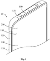
- the mobile terminal 10 includes a terminal device 100, and the terminal device 100 is substantially shaped into a rectangular block, and includes a front surface 110, a rear face 120 opposite the front face 110, and a side peripheral face 130 surrounding the first face 110 and the rear face 120.
- the mobile terminal 10 includes a display screen 200, a display region of the display screen 200 faces a side where the front face 110 is positioned, and the display screen 200 is configured to display information and provide an interaction interface for a user.
- the mobile terminal 10 may include a glass cover plate, the glass cover plate is arranged on one side of the display region of the display screen 200 in a covering manner, and an outer face of the glass cover plate forms all or part of the front face 110.
- the mobile terminal 10 may include a battery cover, the battery cover is positioned on a side back on to the front face 110, the rear face 120 is positioned on the battery cover, and a hollow mounting space is formed between the battery cover and the display screen 200, so as to mount electronic components of the mobile terminal 10, such as a battery and a circuit board.
- the mobile terminal 10 may be a pad and the like.
- the terminal device 100 defines a mounting groove 131 through the side peripheral face 130
- the mobile terminal 10 includes a camera assembly
- the camera assembly includes a transmission mechanism and a camera module 510
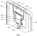
- the transmission mechanism includes a driving mechanism 300, a transmission assembly 400 and a mounting seat 500.
- the driving mechanism 300 is coupled to the terminal device 100
- the transmission assembly 400 includes a first pushing member 410 and a second pushing member 420 coupled to the first pushing member 410
- the first pushing member 410 is connected with the driving mechanism 300.
- the mounting seat 500 is used to connect the first pushing member 410 and the second pushing member 420, the mounting seat 500 is provided with the camera module 510, the camera module 510 includes an incident face 511, and ambient light is transmitted through the incident face 511 and incident to a photosensitive element of the camera module 510.
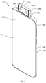
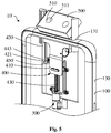
- the driving mechanism 300 enables the first pushing member 410 to move from a first position to a third position via a second position. Referring to Fig. 1 and Fig. 2 , at the first position, the mounting groove 131 accommodates the camera module 510. Referring to Fig. 3 and Fig. 4 , at the second position and the third position, the camera module 510 exposes from the terminal device 100. Referring to Fig.
- the driving mechanism 300 enables the first pushing member 410 to move relative to the second pushing member 420, and the first pushing member 410 enables the mounting seat 500 to rotate, so as to change an orientation of the incident face 511 of the camera module 510.
- a rotating axis of the mounting seat 500 is perpendicular to a movement direction of the first pushing member 410.
- the first position, the second position and the third position are sequentially arranged along a length direction of the mobile terminal 10, and the rotating axis of the mounting seat 500 extends along a width direction of the mobile terminal 10.
- the first position, the second position and the third position may also be sequentially arranged along the width direction of the mobile terminal 10, and the rotating axis of the mounting seat 500 extends along the length direction of the mobile terminal 10.
- the first position, the second position and the third position may also be arranged along another direction, for example, a diagonal extension direction of the mobile terminal 10.
- the orientation of the incident face 511 is opposite an orientation of the display screen 200, and the camera module 510 may realize a function of a rear camera, for example, the user may execute operations of long shot photographing, video recording and the like by the camera module 510.
- the orientation of the incident face 511 is as same as the orientation of the display screen 200, and the camera module 510 may realize a function of a front camera, for example, the user may execute operations of self-timing, video call making and the like by the camera module 510.
- the orientation of the incident face 511 is as same as the orientation of the display screen 200, and the camera module 510 may realize the function of the front camera; and at the third position, the orientation of the incident face 511 is opposite the orientation of the display screen 200, and the camera module 510 may realize the function of the rear camera. Elaborations are omitted here.
- the transmission assembly 400 includes a driving member 430, the mounting seat 500 is rotatably coupled to the second pushing member 420, and the driving member 430 is coupled to the driving mechanism 300.
- a cooperation between the driving member 430 and the first pushing member 410 enables the driving mechanism 300 to drive the second pushing member 420 to move the first pushing member 410 from the first position to the second position; and at the second position, a cooperation between the driving member 430 and the first pushing member 410 enables the driving mechanism 300 to drive the first pushing member 410 to move to the third position relative to the second pushing member 420, and between the second position and the third position, the first pushing member 410 drives the mounting seat 500 to rotate.
- the driving mechanism 300 includes a motor, the motor may be a stepper motor, and the stepper motor is easy to control and relatively high in control accuracy.
- the driving member 430 includes a screw rod, the screw rod is long-strip, and the screw rod is provided with a spiral groove.
- the first pushing member 410 includes a first connecting portion 411 and a second connecting portion 413 coupled to the first connecting portion 411, and the first connecting portion 411 meshes with the screw rod.
- the first connecting portion 411 is arranged on the screw rod in a sleeving manner and forms meshing transmission with the screw rod.
- the first connecting portion 411 may be coupled to a rolling member of a roller structure, the rolling member is arranged in the spiral groove of the screw rod in a rolling manner, the driving mechanism 300 drives the screw rod to rotate, and then the screw rod drives the first connecting portion 411 to move along a length extension direction of the screw rod.
- a reduction box may be arranged between the motor and the screw rod to reduce starting impact of the motor.
- the second connecting portion 413 and the first connecting portion 411 may be formed integrally, and may also be connected detachably, and the second connecting portion 413 is movable relative to the second pushing member 420.
- a rack is arranged at an end portion of the second connecting portion 413, the mounting seat 500 is provided with gear teeth, and the rack meshes with the gear teeth.
- the first connecting portion 411 includes a first wedge block 412
- the second pushing member 420 is provided with a limiting hole 421.
- the transmission assembly 400 includes a second wedge block 441, a pin shaft 443 coupled to the second wedge block 441 and a first elastic member 450 coupled to the pin shaft 443, and the first elastic member 450 is coupled to the terminal device 100. Also referring to Fig. 4 and Fig.
- the first wedge block 412 abuts against the second wedge block 441, and between the second position and the third position, the first wedge block 412 is slidable along the second wedge block 441 and abuts against the second wedge block 441 to drive the second wedge block 441 to compress the first elastic member 450 and clamp the pin shaft 443 to the limiting hole 421.
- positions of the second pushing member 420 and the terminal device 100 are relatively fixed.
- the first pushing member 410 may be driven by the driving member 430 to continue moving to the third position.
- the driving mechanism 300 continues driving the second connecting portion 413 to slide relative to the second pushing member 420, so as to enable the rack to drive the mounting seat 500 to rotate via the gear teeth.
- the first elastic member 450 is a spring, and the spring is arranged on the pin shaft 443 in the sleeving manner.
- the first elastic member 450 may be a structure such as a metal elastic piece, and the first elastic member 450 may also be made from an elastic silicone material or an elastic rubber material.
- the movement direction of the mounting seat 500 is a length direction of the mobile terminal 10.
- the motor is started. If the motor rotates forwards, the motor drives the screw rod to rotate, and the screw rod drives the first connecting portion 411 to move along the length extension direction of the screw rod. Since the rack of the second connecting portion 413 is clamped with the gear teeth of the mounting seat 500, the second pushing member 420 moves, together with the first pushing member 410, to the second position along the length extension direction of the screw rod.
- the first wedge block 412 of the first connecting portion 411 abuts against the second wedge block 441
- the limiting hole 421 of the second pushing member 420 moves to a position of the pin shaft 443
- the first wedge block 412 pushes the second wedge block 441 to move along the width direction of the mobile terminal 10 and compress the first elastic member 450
- the pin shaft 443 enters the limiting hole 421 and is clamped into the limiting hole 421 to relatively fix the positions of the second pushing member 420 and the terminal device 100.
- the mounting seat 500 completely exposes from the mounting groove 131.
- the first wedge block 412 keeps contacting with the second wedge block 441 and continues clamping the pin shaft 443 into the limiting hole 421, the first pushing member 410 moves along the length direction of the screw rod and slides relative to the second pushing member 420, the rack of the first pushing member 410 moves along the length direction of the mobile terminal 10 to drive the gear teeth on the mounting seat 500 to rotate, and the mounting seat 500 further rotates around the width direction of the mobile terminal 10, so as to change the orientation of the incident face 511.
- the camera module 510 may keep a communication connection with a processor in the mobile terminal 10, and then the camera module 510 may shoot at multiple angles in multiple scenarios, for example, panoramic shooting is implemented by the camera module 510, so that the convenience for use and the user experience are both improved.
- the second pushing member 420 is provided with a sliding chute 423, and the sliding chute 423 extends along a movement direction of the mounting seat 500.
- the second connecting portion 413 is provided with a slide-way 415, a limiting column 425 is arranged in the sliding chute 423, and the limiting column 425 is fixedly coupled to the second pushing member 420.
- the limiting column 425 is arranged in the slide-way 415 in a penetration manner. A wall face of the slide way 415 abuts against the limiting column 425 to limit a relative sliding between the second connecting portion 413 and the second pushing member 420 in response to the first pushing member 410 moving from the third position to the second position.
- the first wedge block 412 separates from the second wedge block 441, the pin shaft 443 separates from the limiting hole 421, and the first connecting portion 411 drives the second pushing member 420 to move via the limiting column 425 in response to the first pushing member 410 moving from the second position to the first position,.
- the motor when the mounting seat 500 is at the third position, the motor is started, the motor rotates backwards, the motor drives the screw rod to rotate backwards, and the screw rod enables the first connecting portion 411 to move along the length extension direction of the screw rod. Since the pin shaft 443 is clamped into the limiting hole 421 to relatively fix the positions of the second pushing member 420 and the terminal device 100, the first pushing member 420 moves along the length direction of the screw rod and is slidable relative to the second pushing member 420 in the sliding chute 423 of the second pushing member 420 to drive the gear teeth on the mounting seat 500 to rotate, and the mounting seat 500 further rotates backwards around the width direction of the mobile terminal 10, so as to change the orientation of the incident face 511.
- the screw rod continues driving the first pushing member 410 to move along the length direction of the mobile terminal 10, and then the first connecting portion 411 drives the second pushing member 420 to move to the first position via the limiting column 425, so as to accommodate the mounting seat 500 in the mounting groove 131.
- the camera module 510 may also keep the communication connection with the processor in the mobile terminal 10, and then the camera module 510 may shoot at multiple angles in multiple scenarios, for example, panoramic shooting is implemented by the camera module 510, so that the convenience for use and the user experience are both improved. It can be understood that a distance between the second position and the third position is designed such that the mounting seat 500, when the first pushing member 410 moves from the second position to the third position, may rotate 180 degrees to enable the camera module 510 to serve as a front/rear camera.
- the first pushing member 410 moves relative to the terminal device 100 from the first position to the third position by the second position, the mounting groove 131 accommodates the camera module 510 at the first position, and the camera module 510 exposes from the mobile terminal 10 at the second position and the third position.
- a part of an area of the side where the display screen 200 of the mobile terminal 10 positioned is prevented from being occupied by the camera, and a screen-to-body ratio of the mobile terminal 10 is increased.
- the screen-to-body ratio of the mobile terminal 10 adopting the structure may be over 85%.
- the driving mechanism 300 drives, by the transmission assembly 400, the mounting seat 500 to rotate to change the orientation of the incident face 511 of the camera module 510.
- the camera module 510 may implement shooting at multiple angles in multiple scenarios, which is adoptable for improving convenience for use and improving the user experience.
- the transmission assembly 400 includes a second elastic member 460, the second elastic member 460 is of a torsion spring structure, and the second elastic member 460 connects the first pushing member 410 and the second pushing member 420.
- the first pushing member 410 compresses the second elastic member 460 in response to the first pushing member 410 moving from the second position to the third position, and when the first pushing member 410 reaches the third position, the second elastic member 460 is maximally deformed.
- the mounting seat 500 rotates, the second elastic member 460 keeps returning from deformation in response to the first pushing member 410 moving from the third position to the second position; and when the first pushing member 410 moves to the second position, the second elastic member 460 returns to an initial state and, in such case, the elasticity of the second elastic member 460 does not apply and the mounting seat 500 rotates till a stopping effect is achieved, so that a feedback is provided for the user.
- the transmission assembly 400 includes a balancing rod 470, and a length extension direction of the balancing rod 470 is as same as the length extension direction of the screw rod.
- the balancing rod 470 is fixedly coupled to the terminal device 100, and the first connecting portion 411 is arranged in the balancing rod 470 in the penetration manner and slidable relative to the balancing rod 470.
- Arrangement of the balancing rod 470 is adoptable for stable sliding the first pushing member 410, so that movement stability of the mounting seat 500 is improved.
- the driving mechanism 300 includes the motor, and the motor is fixedly coupled to the terminal device 100.
- the driving member 430 includes a driving gear teeth
- the first pushing member 410 includes the first connecting portion 411 and second connecting portion 413 coupled to the first connecting portion 411
- the first connecting portion 411 is provided with a driving rack
- the driving rack extends along the movement direction of the mounting seat 500.
- the first connecting portion 411 meshes with the driving gear teeth
- the second connecting portion 413 is arranged at the second pushing member 420 in a sliding manner
- the second connecting portion 413 is provided with the rack
- the mounting seat 500 is provided with the gear teeth
- the rack meshes with the gear teeth.
- the driving member 430 and the first pushing member 410 also implement movement of the first pushing member 410 from the first position to the third position through the second position and implement movement of the first pushing member 410 from the third position to the first position through the second position. Elaborations are omitted here.
- Fig. 13 is a structure of a terminal device 100 according to an embodiment of the present disclosure.
- the terminal device 100 includes components such as a Radio Frequency (RF) circuit 501, a memory 502 including one or more than one computer-readable storage medium, an input unit 503, a display unit 504, a sensor 504, an audio circuit 506, a Wireless Fidelity (WiFi) module 507, a processor 508 including a plurality of processing cores and a power supply 509.
- RF Radio Frequency
- a memory 502 including one or more than one computer-readable storage medium
- WiFi Wireless Fidelity
- the RF circuit 501 may be configured to receive and transmit information or receive and send a signal during a call, particularly, transmitting, after receiving downlink information of a base station, the downlink information to the plurality of processing cores of the processor 508 for processing and, in addition, sending involved uplink data to the base station.
- the RF circuit 501 includes, but not limited to, an antenna, at least one amplifier, a tuner, one or more oscillators, a Subscriber Identity Module (SIM) card, a transceiver, a coupler, a Low Noise Amplifier (LNA), a duplexer and the like.
- SIM Subscriber Identity Module
- LNA Low Noise Amplifier
- the RF circuit 501 may also communicate with a network and another device by wireless communication.
- GSM Global System of Mobile communication
- GPRS General Packet Radio Service
- CDMA Code Division Multiple Access
- WCDMA Wideband Code Division Multiple Access
- LTE Long Term Evolution
- SMS Short Messaging Service
- the memory 502 may be configured to store an application program and data.
- the application program stored in the memory 502 includes an executable code.
- the application program may form various functional modules.
- the processor 508 runs the application program stored in the memory 502, thereby executing various functional applications and data processing.
- the memory 502 may include a program storage region and a data storage region.
- the program storage region may store an operating system, an application program required by at least one function (for example, a sound playing function and an image playing function) and the like.
- the data storage region may store data (for example, audio data and a phone book) created according to use of the terminal device 100 and the like.
- the memory 502 may include a high-speed random access memory and may further include a nonvolatile memory, for example, at least one disk storage device, flash memory device or other volatile solid-state storage device.
- the memory 502 may further include a memory controller for providing access to the memory 502 for the processor 508 and the input unit 503.
- the input unit 503 is configured to receive input digital and character information or user characteristic information (for example, a fingerprint) and generate keyboard, mouse, joystick and optical trackball signal input related to user setting and function control.
- the input unit 503 may include a touch-sensitive face and other input devices.
- the touch-sensitive face also called a touch display screen or a touch panel, may collect a touch operation of a user thereon or nearby (for example, an operation executed by the user with any proper object or accessory such as a finger and a stylus on the touch-sensitive face or nearby the touch-sensitive face) and drive a corresponding connection device according to a preset program.
- the touch-sensitive face includes two parts, i.e., a touch detection device and a touch controller.
- the touch detection device detects a touch direction of the user, detects a signal generated by the touch operation and transmits the signal to the touch controller.
- the touch controller receives touch information from the touch detection device, converts it into a touch point coordinate and transmits it to the processor 508, and may receive and execute a command sent by the processor 508.
- the display unit 504 is configured to display information input by the user or information provided for the user and various graphical user interfaces of the terminal device 100. These graphical user interfaces may be formed by graphics, texts, icons, videos and any combination thereof.
- the display unit 504 includes a display panel.
- the display panel is configured in form of a Liquid Crystal Display (LCD) and an Organic Light-Emitting Diode (OLED).
- the touch-sensitive face is covered by the display panel. After detecting the touch operation thereon or nearby, the touch-sensitive face transmits it to the processor 508 to determine a type of a touch event. Then, the processor 508 provides corresponding visual output on the display panel according to the type of the touch event.
- LCD Liquid Crystal Display
- OLED Organic Light-Emitting Diode
- the touch-sensitive face and the display panel realize input and output functions as two independent components.
- the touch-sensitive face and the display panel may be integrated to realize the input and output functions.
- the display screen 200 may include the input unit 503 and the display unit 504.
- the terminal device 100 may further include at least one sensor 505, for example, a light sensor, a motion sensor and another sensor.
- the light sensor may include an ambient light sensor and a proximity sensor.
- the ambient light sensor may regulate brightness of the display panel according to brightness of ambient light
- the proximity sensor may turn off the display panel and/or backlight when the terminal device 100 is moved to an ear of a user.
- a gravitational acceleration sensor may detect a magnitude of an acceleration in each direction (usually three axes), may detect a magnitude and direction of the gravity under a motionless condition, and may be configured for an application recognizing a posture of the mobile phone (for example, landscape and portrait switching, a related game and magnetometer posture calibration), a vibration recognition related function and the like (for example, a pedometer and knocking).
- Other sensors for example, a gyroscope, a barometer, a hygrometer, a thermometer and an infrared sensor, which may be configured in the terminal device 100 will not be elaborated herein.
- the audio circuit 506 may provide an audio interface between the user and the terminal device 100 by a loudspeaker and a microphone.
- the audio circuit 506 may convert received audio data into an electric signal for transmission to the speaker, and the speaker converts it into a sound signal for output.
- the microphone converts a collected sound signal into an electric signal
- the audio circuit 506 receives and converts it into audio data
- the audio data is output to the processor 508 for processing and sent to, for example, another terminal device 100 by the RF circuit 501, or the audio data is output to the memory 502 for further processing.
- the audio circuit 506 may further include an earphone jack for providing communication between an external earphone and the terminal device 100.
- WiFi relates to a short-distance wireless transmission technology.
- the terminal device 100 may help the user receive and send an electronic mail, browse a webpage, access streaming media and the like through the WiFi module 507, and wireless wideband Internet access is provided for the user.
- the WiFi module 507 is shown in Fig. 13 , it can be understood that it is not a necessary composition of the terminal device 100 and may completely be omitted according to a requirement without changing the scope of the essence of the invention.
- the processor 508 is a control center of the terminal device 100 and connects each part of the terminal device 100 by use of various interfaces and lines and executes various functions and data processing of the terminal device 100 by running or executing the application program stored in the memory 502 and calling data stored in the memory 502, thereby monitoring the whole terminal device 100.
- the processor 508 may include a plurality of processing cores.
- the processor 508 may integrate an application processor and a modulation and demodulation processor.
- the application processor mainly processes the operating system, a user interface, an application program and the like.
- the modulation and demodulation processor mainly processes wireless communication. It can be understood that the modulation and demodulation processor may also not be integrated into the processor 508.
- the terminal device 100 further includes a power supply 509 supplying power to each component.
- the power supply 509 may be logically connected with the processor 508 by a power management system, thereby realizing functions of charging and discharging management, power consumption management and the like by the power management system.
- the power supply 509 may further include one or more than one direct current or alternating current power supply, rechargeable system, power failure detection circuit, power converter or inverter and power state indicator and any other component.
- the terminal device 100 may further include a Bluetooth module and the like, which will not be elaborated herein.
- each of the modules may be implemented as an independent entity, and may also be freely combined for implementation as the same or a plurality of entities. Specific implementation of each of the modules may refer to the method embodiment and will not be elaborated here.
Landscapes
- Engineering & Computer Science (AREA)
- General Engineering & Computer Science (AREA)
- Signal Processing (AREA)
- Computer Hardware Design (AREA)
- Theoretical Computer Science (AREA)
- Human Computer Interaction (AREA)
- Physics & Mathematics (AREA)
- General Physics & Mathematics (AREA)
- Multimedia (AREA)
- Mechanical Engineering (AREA)
- Telephone Set Structure (AREA)
Applications Claiming Priority (1)
| Application Number | Priority Date | Filing Date | Title |
|---|---|---|---|
| CN201822012084.7U CN209572070U (zh) | 2018-11-30 | 2018-11-30 | 传动模组、传动机构、摄像头组合件和移动终端 |
Publications (2)
| Publication Number | Publication Date |
|---|---|
| EP3661175A1 true EP3661175A1 (de) | 2020-06-03 |
| EP3661175B1 EP3661175B1 (de) | 2023-07-12 |
Family
ID=68329978
Family Applications (1)
| Application Number | Title | Priority Date | Filing Date |
|---|---|---|---|
| EP19212532.6A Active EP3661175B1 (de) | 2018-11-30 | 2019-11-29 | Übertragungsmodul, übertragungsmechanismus und mobiles endgerät |
Country Status (4)
| Country | Link |
|---|---|
| US (1) | US11140249B2 (de) |
| EP (1) | EP3661175B1 (de) |
| CN (1) | CN209572070U (de) |
| WO (1) | WO2020108273A1 (de) |
Families Citing this family (26)
| Publication number | Priority date | Publication date | Assignee | Title |
|---|---|---|---|---|
| CN209572070U (zh) | 2018-11-30 | 2019-11-01 | Oppo广东移动通信有限公司 | 传动模组、传动机构、摄像头组合件和移动终端 |
| CN109561179A (zh) * | 2018-12-04 | 2019-04-02 | 武汉华星光电半导体显示技术有限公司 | 壳体组件以及电子设备 |
| KR102619948B1 (ko) * | 2019-04-09 | 2024-01-03 | 삼성전자주식회사 | 회전식 광학 모듈을 포함하는 전자 장치 |
| CN111835887B (zh) * | 2019-04-16 | 2022-04-08 | 北京小米移动软件有限公司 | 摄像头结构和电子设备 |
| CN111917904B (zh) * | 2019-05-10 | 2022-05-06 | 深圳富泰宏精密工业有限公司 | 控制方法及电子装置 |
| CN110784574B (zh) * | 2019-11-04 | 2021-02-02 | 深圳纳百鑫光学有限公司 | 一种手机摄像头的旋转调节装置 |
| CN211152025U (zh) * | 2019-12-03 | 2020-07-31 | 富港电子(昆山)有限公司 | 应用于笔记型计算机的磁吸式摄像头 |
| CN111182180B (zh) * | 2019-12-23 | 2021-10-22 | 诚瑞光学(常州)股份有限公司 | 一种摄像装置、电子设备和电子设备的控制方法 |
| CN111225134B (zh) * | 2020-01-15 | 2021-07-27 | Oppo广东移动通信有限公司 | 一种摄像头模组及其电子设备 |
| CN113199986B (zh) * | 2020-01-16 | 2022-07-29 | 荣耀终端有限公司 | 运动结构、开合装置及移动终端 |
| CN111427419B (zh) * | 2020-03-18 | 2021-11-23 | 维沃移动通信有限公司 | 翻转功能组件及电子设备 |
| CN113497870B (zh) | 2020-04-07 | 2022-09-23 | 华为技术有限公司 | 一种摄像头组件及电子设备 |
| CN111988501B (zh) * | 2020-07-09 | 2021-09-28 | 诚瑞光学(常州)股份有限公司 | 镜头传动装置及移动终端 |
| CN114500778B (zh) * | 2020-11-11 | 2023-10-24 | 北京小米移动软件有限公司 | 摄像头模组及电子设备 |
| CN114508649B (zh) * | 2020-11-16 | 2024-07-26 | 群光电子股份有限公司 | 电子装置与摄影装置 |
| CN112637494B (zh) | 2020-12-21 | 2022-05-17 | 维沃移动通信有限公司 | 电子设备及其控制方法、控制装置和终端设备 |
| US11435781B1 (en) * | 2021-03-23 | 2022-09-06 | Lenovo (Singapore) Pte. Ltd. | Computing device |
| CN113055572B (zh) * | 2021-03-26 | 2022-11-22 | 联想(北京)有限公司 | 一种电子设备 |
| CN113653892B (zh) * | 2021-08-03 | 2022-12-23 | 深圳市麦唯智能科技有限公司 | 应用于平板电脑的多角度摄像头 |
| TWI801983B (zh) * | 2021-08-31 | 2023-05-11 | 技嘉科技股份有限公司 | 顯示裝置與包括其之電子系統 |
| TWI783777B (zh) * | 2021-11-11 | 2022-11-11 | 佳世達科技股份有限公司 | 攝像組件及具有其之顯示裝置 |
| CN114338989B (zh) * | 2021-12-29 | 2024-02-23 | 深圳创维-Rgb电子有限公司 | 摄像头及电子产品 |
| US12348870B2 (en) * | 2022-04-09 | 2025-07-01 | Corephotonics Ltd. | Spin-out 360-degree camera for smartphone |
| US12244929B1 (en) * | 2022-09-29 | 2025-03-04 | Amazon Technologies, Inc. | Device with moveable portion including sensors |
| US12356122B1 (en) | 2022-09-29 | 2025-07-08 | Amazon Technologies, Inc. | Mechanism with moveable sensor head |
| US20260026494A1 (en) * | 2024-07-25 | 2026-01-29 | Shenzhen Kaisennick Intelligent Technology Co., Ltd. | Outdoor hunting recorder |
Citations (3)
| Publication number | Priority date | Publication date | Assignee | Title |
|---|---|---|---|---|
| CN207926665U (zh) * | 2018-02-09 | 2018-09-28 | 广东欧珀移动通信有限公司 | 移动终端 |
| CN207968579U (zh) * | 2018-02-09 | 2018-10-12 | 广东欧珀移动通信有限公司 | 移动终端 |
| EP3396933A1 (de) * | 2017-04-28 | 2018-10-31 | Guangdong OPPO Mobile Telecommunications Corp., Ltd. | Mobile elektronische vorrichtung |
Family Cites Families (27)
| Publication number | Priority date | Publication date | Assignee | Title |
|---|---|---|---|---|
| KR101074284B1 (ko) * | 2004-09-23 | 2011-10-17 | 에이저 시스템즈 인크 | 파노라마 이미지 메이킹 능력을 갖는 이동 통신 장치 |
| US7435018B2 (en) * | 2006-06-28 | 2008-10-14 | Inventec Corporation | Hidden image capturing device |
| US9288471B1 (en) * | 2013-02-28 | 2016-03-15 | Amazon Technologies, Inc. | Rotatable imaging assembly for providing multiple fields of view |
| US10021296B2 (en) * | 2013-12-31 | 2018-07-10 | Futurewei Technologies, Inc. | Automatic rotatable camera for panorama taking in mobile terminals |
| CN204216938U (zh) | 2014-06-11 | 2015-03-18 | 深圳市朵唯志远科技有限公司 | 旋转摄像手机 |
| CN203968178U (zh) * | 2014-06-25 | 2014-11-26 | 合肥京东方显示光源有限公司 | 一种移动通讯装置 |
| CN109246262B (zh) * | 2014-07-23 | 2021-10-01 | 荣耀终端有限公司 | 一种终端设备 |
| TWI548966B (zh) * | 2014-12-29 | 2016-09-11 | 鴻海精密工業股份有限公司 | 電子裝置 |
| CN105141815B (zh) * | 2015-09-02 | 2018-07-31 | 小米科技有限责任公司 | 摄像头自动弹出装置和终端 |
| US9736383B2 (en) * | 2015-10-30 | 2017-08-15 | Essential Products, Inc. | Apparatus and method to maximize the display area of a mobile device |
| US9762781B2 (en) * | 2015-10-30 | 2017-09-12 | Essential Products, Inc. | Apparatus and method to maximize the display area of a mobile device by increasing the size of the display without necessarily increasing the size of the phone |
| KR102604966B1 (ko) * | 2017-02-24 | 2023-11-22 | 엘지전자 주식회사 | 이동 단말기 |
| CN107197133B (zh) | 2017-07-21 | 2019-11-29 | 维沃移动通信有限公司 | 一种移动终端及摄像头组件 |
| US20190033926A1 (en) * | 2017-07-26 | 2019-01-31 | Wuhan China Star Optoelectronics Semiconductor Display Technology Co., Ltd. | Mobile terminal |
| WO2019085535A1 (en) * | 2017-10-31 | 2019-05-09 | Guangdong Oppo Mobile Telecommunications Corp., Ltd. | Functional device and electronic apparatus |
| EP3481035B1 (de) * | 2017-11-03 | 2020-07-29 | Guangdong Oppo Mobile Telecommunications Corp., Ltd. | Versenkbare kamera eines mobilfunktelefons mittels elektromagnetischer kraft |
| CN107911579A (zh) * | 2017-11-07 | 2018-04-13 | 广东欧珀移动通信有限公司 | 移动终端 |
| CN107872609A (zh) * | 2017-11-07 | 2018-04-03 | 广东欧珀移动通信有限公司 | 摄像头组装结构及移动终端 |
| CN207802113U (zh) * | 2017-11-07 | 2018-08-31 | 广东欧珀移动通信有限公司 | 摄像头组装结构及移动终端 |
| CN107888809A (zh) * | 2017-11-07 | 2018-04-06 | 广东欧珀移动通信有限公司 | 摄像头组装结构及移动终端 |
| CN109862226B (zh) * | 2017-11-30 | 2021-04-27 | Oppo广东移动通信有限公司 | 一种摄像头组件、移动终端及其摄像头组件的控制方法 |
| CN113099083B (zh) * | 2017-11-30 | 2023-04-18 | Oppo广东移动通信有限公司 | 摄像头组件、移动终端及其摄像头组件的控制方法 |
| US10567558B2 (en) * | 2017-12-06 | 2020-02-18 | Shenzhen Zhaowei Machinery & Electronics Co., Ltd. | Camera extending and retracting device and mobile phone |
| CN207926662U (zh) * | 2018-02-09 | 2018-09-28 | 广东欧珀移动通信有限公司 | 移动终端 |
| CN207926663U (zh) * | 2018-02-09 | 2018-09-28 | 广东欧珀移动通信有限公司 | 移动终端 |
| CN208174751U (zh) * | 2018-02-09 | 2018-11-30 | Oppo广东移动通信有限公司 | 移动终端 |
| CN209572070U (zh) * | 2018-11-30 | 2019-11-01 | Oppo广东移动通信有限公司 | 传动模组、传动机构、摄像头组合件和移动终端 |
-
2018
- 2018-11-30 CN CN201822012084.7U patent/CN209572070U/zh not_active Expired - Fee Related
-
2019
- 2019-11-08 WO PCT/CN2019/116695 patent/WO2020108273A1/en not_active Ceased
- 2019-11-27 US US16/698,660 patent/US11140249B2/en active Active
- 2019-11-29 EP EP19212532.6A patent/EP3661175B1/de active Active
Patent Citations (4)
| Publication number | Priority date | Publication date | Assignee | Title |
|---|---|---|---|---|
| EP3396933A1 (de) * | 2017-04-28 | 2018-10-31 | Guangdong OPPO Mobile Telecommunications Corp., Ltd. | Mobile elektronische vorrichtung |
| CN207926665U (zh) * | 2018-02-09 | 2018-09-28 | 广东欧珀移动通信有限公司 | 移动终端 |
| CN207968579U (zh) * | 2018-02-09 | 2018-10-12 | 广东欧珀移动通信有限公司 | 移动终端 |
| EP3525428A1 (de) * | 2018-02-09 | 2019-08-14 | Guangdong Oppo Mobile Telecommunications Corp., Ltd. | Elektronische vorrichtung |
Also Published As
| Publication number | Publication date |
|---|---|
| US11140249B2 (en) | 2021-10-05 |
| EP3661175B1 (de) | 2023-07-12 |
| WO2020108273A1 (en) | 2020-06-04 |
| US20200177715A1 (en) | 2020-06-04 |
| CN209572070U (zh) | 2019-11-01 |
Similar Documents
| Publication | Publication Date | Title |
|---|---|---|
| EP3661175B1 (de) | Übertragungsmodul, übertragungsmechanismus und mobiles endgerät | |
| US11297173B2 (en) | Transmission mechanism, driving mechanism assembly, and mobile terminal | |
| US20220201167A1 (en) | Camera module and terminal device | |
| CN108600453B (zh) | 电子设备 | |
| CN108540608B (zh) | 电子装置 | |
| EP3576399B1 (de) | Elektronische vorrichtung und fotografiesteuerungsverfahren dafür | |
| CN108833618B (zh) | 电子装置 | |
| CN108376019A (zh) | 电子装置 | |
| CN209330169U (zh) | 移动终端 | |
| EP3972229B1 (de) | Endgerätevorrichtung | |
| WO2020038148A1 (zh) | 移动终端 | |
| CN107944308B (zh) | 电子装置及电子装置的跌落保护方法 | |
| CN108093100B (zh) | 电子装置 | |
| WO2023185084A1 (zh) | 摄像头模组及电子设备 | |
| CN108650346B (zh) | 电子装置 | |
| WO2020199885A1 (zh) | 终端设备 | |
| HK40030526A (en) | Transmission module, transmission mechanism, and mobile terminal | |
| HK40030526B (en) | Transmission module, transmission mechanism, and mobile terminal | |
| CN209105226U (zh) | 移动终端 | |
| CN209170472U (zh) | 保护壳与设备套装 | |
| WO2020038153A1 (zh) | 移动终端 | |
| CN209982523U (zh) | 终端设备 | |
| CN209105225U (zh) | 移动终端 | |
| CN110661955A (zh) | 摄像头模组的控制方法 | |
| CN121078305A (zh) | 壳体组件、外置拍摄装置及电子设备 |
Legal Events
| Date | Code | Title | Description |
|---|---|---|---|
| PUAI | Public reference made under article 153(3) epc to a published international application that has entered the european phase |
Free format text: ORIGINAL CODE: 0009012 |
|
| STAA | Information on the status of an ep patent application or granted ep patent |
Free format text: STATUS: THE APPLICATION HAS BEEN PUBLISHED |
|
| AK | Designated contracting states |
Kind code of ref document: A1 Designated state(s): AL AT BE BG CH CY CZ DE DK EE ES FI FR GB GR HR HU IE IS IT LI LT LU LV MC MK MT NL NO PL PT RO RS SE SI SK SM TR |
|
| AX | Request for extension of the european patent |
Extension state: BA ME |
|
| STAA | Information on the status of an ep patent application or granted ep patent |
Free format text: STATUS: REQUEST FOR EXAMINATION WAS MADE |
|
| 17P | Request for examination filed |
Effective date: 20201028 |
|
| RBV | Designated contracting states (corrected) |
Designated state(s): AL AT BE BG CH CY CZ DE DK EE ES FI FR GB GR HR HU IE IS IT LI LT LU LV MC MK MT NL NO PL PT RO RS SE SI SK SM TR |
|
| REG | Reference to a national code |
Ref country code: HK Ref legal event code: DE Ref document number: 40030526 Country of ref document: HK |
|
| STAA | Information on the status of an ep patent application or granted ep patent |
Free format text: STATUS: EXAMINATION IS IN PROGRESS |
|
| 17Q | First examination report despatched |
Effective date: 20211105 |
|
| GRAP | Despatch of communication of intention to grant a patent |
Free format text: ORIGINAL CODE: EPIDOSNIGR1 |
|
| STAA | Information on the status of an ep patent application or granted ep patent |
Free format text: STATUS: GRANT OF PATENT IS INTENDED |
|
| RIC1 | Information provided on ipc code assigned before grant |
Ipc: G06F 1/16 20060101ALI20230217BHEP Ipc: H04M 1/02 20060101AFI20230217BHEP |
|
| INTG | Intention to grant announced |
Effective date: 20230328 |
|
| GRAS | Grant fee paid |
Free format text: ORIGINAL CODE: EPIDOSNIGR3 |
|
| GRAA | (expected) grant |
Free format text: ORIGINAL CODE: 0009210 |
|
| STAA | Information on the status of an ep patent application or granted ep patent |
Free format text: STATUS: THE PATENT HAS BEEN GRANTED |
|
| AK | Designated contracting states |
Kind code of ref document: B1 Designated state(s): AL AT BE BG CH CY CZ DE DK EE ES FI FR GB GR HR HU IE IS IT LI LT LU LV MC MK MT NL NO PL PT RO RS SE SI SK SM TR |
|
| REG | Reference to a national code |
Ref country code: CH Ref legal event code: EP |
|
| REG | Reference to a national code |
Ref country code: IE Ref legal event code: FG4D |
|
| REG | Reference to a national code |
Ref country code: DE Ref legal event code: R096 Ref document number: 602019032473 Country of ref document: DE |
|
| REG | Reference to a national code |
Ref country code: LT Ref legal event code: MG9D |
|
| REG | Reference to a national code |
Ref country code: NL Ref legal event code: MP Effective date: 20230712 |
|
| P01 | Opt-out of the competence of the unified patent court (upc) registered |
Effective date: 20231016 |
|
| REG | Reference to a national code |
Ref country code: AT Ref legal event code: MK05 Ref document number: 1588306 Country of ref document: AT Kind code of ref document: T Effective date: 20230712 |
|
| PG25 | Lapsed in a contracting state [announced via postgrant information from national office to epo] |
Ref country code: NL Free format text: LAPSE BECAUSE OF FAILURE TO SUBMIT A TRANSLATION OF THE DESCRIPTION OR TO PAY THE FEE WITHIN THE PRESCRIBED TIME-LIMIT Effective date: 20230712 |
|
| PG25 | Lapsed in a contracting state [announced via postgrant information from national office to epo] |
Ref country code: GR Free format text: LAPSE BECAUSE OF FAILURE TO SUBMIT A TRANSLATION OF THE DESCRIPTION OR TO PAY THE FEE WITHIN THE PRESCRIBED TIME-LIMIT Effective date: 20231013 |
|
| PG25 | Lapsed in a contracting state [announced via postgrant information from national office to epo] |
Ref country code: ES Free format text: LAPSE BECAUSE OF FAILURE TO SUBMIT A TRANSLATION OF THE DESCRIPTION OR TO PAY THE FEE WITHIN THE PRESCRIBED TIME-LIMIT Effective date: 20230712 |
|
| PG25 | Lapsed in a contracting state [announced via postgrant information from national office to epo] |
Ref country code: IS Free format text: LAPSE BECAUSE OF FAILURE TO SUBMIT A TRANSLATION OF THE DESCRIPTION OR TO PAY THE FEE WITHIN THE PRESCRIBED TIME-LIMIT Effective date: 20231112 |
|
| PG25 | Lapsed in a contracting state [announced via postgrant information from national office to epo] |
Ref country code: SE Free format text: LAPSE BECAUSE OF FAILURE TO SUBMIT A TRANSLATION OF THE DESCRIPTION OR TO PAY THE FEE WITHIN THE PRESCRIBED TIME-LIMIT Effective date: 20230712 Ref country code: RS Free format text: LAPSE BECAUSE OF FAILURE TO SUBMIT A TRANSLATION OF THE DESCRIPTION OR TO PAY THE FEE WITHIN THE PRESCRIBED TIME-LIMIT Effective date: 20230712 Ref country code: PT Free format text: LAPSE BECAUSE OF FAILURE TO SUBMIT A TRANSLATION OF THE DESCRIPTION OR TO PAY THE FEE WITHIN THE PRESCRIBED TIME-LIMIT Effective date: 20231113 Ref country code: NO Free format text: LAPSE BECAUSE OF FAILURE TO SUBMIT A TRANSLATION OF THE DESCRIPTION OR TO PAY THE FEE WITHIN THE PRESCRIBED TIME-LIMIT Effective date: 20231012 Ref country code: LV Free format text: LAPSE BECAUSE OF FAILURE TO SUBMIT A TRANSLATION OF THE DESCRIPTION OR TO PAY THE FEE WITHIN THE PRESCRIBED TIME-LIMIT Effective date: 20230712 Ref country code: LT Free format text: LAPSE BECAUSE OF FAILURE TO SUBMIT A TRANSLATION OF THE DESCRIPTION OR TO PAY THE FEE WITHIN THE PRESCRIBED TIME-LIMIT Effective date: 20230712 Ref country code: IS Free format text: LAPSE BECAUSE OF FAILURE TO SUBMIT A TRANSLATION OF THE DESCRIPTION OR TO PAY THE FEE WITHIN THE PRESCRIBED TIME-LIMIT Effective date: 20231112 Ref country code: HR Free format text: LAPSE BECAUSE OF FAILURE TO SUBMIT A TRANSLATION OF THE DESCRIPTION OR TO PAY THE FEE WITHIN THE PRESCRIBED TIME-LIMIT Effective date: 20230712 Ref country code: GR Free format text: LAPSE BECAUSE OF FAILURE TO SUBMIT A TRANSLATION OF THE DESCRIPTION OR TO PAY THE FEE WITHIN THE PRESCRIBED TIME-LIMIT Effective date: 20231013 Ref country code: FI Free format text: LAPSE BECAUSE OF FAILURE TO SUBMIT A TRANSLATION OF THE DESCRIPTION OR TO PAY THE FEE WITHIN THE PRESCRIBED TIME-LIMIT Effective date: 20230712 Ref country code: ES Free format text: LAPSE BECAUSE OF FAILURE TO SUBMIT A TRANSLATION OF THE DESCRIPTION OR TO PAY THE FEE WITHIN THE PRESCRIBED TIME-LIMIT Effective date: 20230712 Ref country code: AT Free format text: LAPSE BECAUSE OF FAILURE TO SUBMIT A TRANSLATION OF THE DESCRIPTION OR TO PAY THE FEE WITHIN THE PRESCRIBED TIME-LIMIT Effective date: 20230712 |
|
| PGFP | Annual fee paid to national office [announced via postgrant information from national office to epo] |
Ref country code: FR Payment date: 20231120 Year of fee payment: 5 |
|
| PG25 | Lapsed in a contracting state [announced via postgrant information from national office to epo] |
Ref country code: PL Free format text: LAPSE BECAUSE OF FAILURE TO SUBMIT A TRANSLATION OF THE DESCRIPTION OR TO PAY THE FEE WITHIN THE PRESCRIBED TIME-LIMIT Effective date: 20230712 |
|
| REG | Reference to a national code |
Ref country code: DE Ref legal event code: R097 Ref document number: 602019032473 Country of ref document: DE |
|
| PG25 | Lapsed in a contracting state [announced via postgrant information from national office to epo] |
Ref country code: SM Free format text: LAPSE BECAUSE OF FAILURE TO SUBMIT A TRANSLATION OF THE DESCRIPTION OR TO PAY THE FEE WITHIN THE PRESCRIBED TIME-LIMIT Effective date: 20230712 Ref country code: RO Free format text: LAPSE BECAUSE OF FAILURE TO SUBMIT A TRANSLATION OF THE DESCRIPTION OR TO PAY THE FEE WITHIN THE PRESCRIBED TIME-LIMIT Effective date: 20230712 Ref country code: EE Free format text: LAPSE BECAUSE OF FAILURE TO SUBMIT A TRANSLATION OF THE DESCRIPTION OR TO PAY THE FEE WITHIN THE PRESCRIBED TIME-LIMIT Effective date: 20230712 Ref country code: DK Free format text: LAPSE BECAUSE OF FAILURE TO SUBMIT A TRANSLATION OF THE DESCRIPTION OR TO PAY THE FEE WITHIN THE PRESCRIBED TIME-LIMIT Effective date: 20230712 Ref country code: CZ Free format text: LAPSE BECAUSE OF FAILURE TO SUBMIT A TRANSLATION OF THE DESCRIPTION OR TO PAY THE FEE WITHIN THE PRESCRIBED TIME-LIMIT Effective date: 20230712 Ref country code: SK Free format text: LAPSE BECAUSE OF FAILURE TO SUBMIT A TRANSLATION OF THE DESCRIPTION OR TO PAY THE FEE WITHIN THE PRESCRIBED TIME-LIMIT Effective date: 20230712 |
|
| PLBE | No opposition filed within time limit |
Free format text: ORIGINAL CODE: 0009261 |
|
| STAA | Information on the status of an ep patent application or granted ep patent |
Free format text: STATUS: NO OPPOSITION FILED WITHIN TIME LIMIT |
|
| PG25 | Lapsed in a contracting state [announced via postgrant information from national office to epo] |
Ref country code: IT Free format text: LAPSE BECAUSE OF FAILURE TO SUBMIT A TRANSLATION OF THE DESCRIPTION OR TO PAY THE FEE WITHIN THE PRESCRIBED TIME-LIMIT Effective date: 20230712 |
|
| 26N | No opposition filed |
Effective date: 20240415 |
|
| REG | Reference to a national code |
Ref country code: CH Ref legal event code: PL |
|
| PG25 | Lapsed in a contracting state [announced via postgrant information from national office to epo] |
Ref country code: MC Free format text: LAPSE BECAUSE OF FAILURE TO SUBMIT A TRANSLATION OF THE DESCRIPTION OR TO PAY THE FEE WITHIN THE PRESCRIBED TIME-LIMIT Effective date: 20230712 |
|
| PG25 | Lapsed in a contracting state [announced via postgrant information from national office to epo] |
Ref country code: LU Free format text: LAPSE BECAUSE OF NON-PAYMENT OF DUE FEES Effective date: 20231129 |
|
| PG25 | Lapsed in a contracting state [announced via postgrant information from national office to epo] |
Ref country code: CH Free format text: LAPSE BECAUSE OF NON-PAYMENT OF DUE FEES Effective date: 20231130 |
|
| PG25 | Lapsed in a contracting state [announced via postgrant information from national office to epo] |
Ref country code: MC Free format text: LAPSE BECAUSE OF FAILURE TO SUBMIT A TRANSLATION OF THE DESCRIPTION OR TO PAY THE FEE WITHIN THE PRESCRIBED TIME-LIMIT Effective date: 20230712 Ref country code: LU Free format text: LAPSE BECAUSE OF NON-PAYMENT OF DUE FEES Effective date: 20231129 Ref country code: CH Free format text: LAPSE BECAUSE OF NON-PAYMENT OF DUE FEES Effective date: 20231130 Ref country code: SI Free format text: LAPSE BECAUSE OF FAILURE TO SUBMIT A TRANSLATION OF THE DESCRIPTION OR TO PAY THE FEE WITHIN THE PRESCRIBED TIME-LIMIT Effective date: 20230712 |
|
| REG | Reference to a national code |
Ref country code: BE Ref legal event code: MM Effective date: 20231130 |
|
| REG | Reference to a national code |
Ref country code: IE Ref legal event code: MM4A |
|
| PG25 | Lapsed in a contracting state [announced via postgrant information from national office to epo] |
Ref country code: IE Free format text: LAPSE BECAUSE OF NON-PAYMENT OF DUE FEES Effective date: 20231129 |
|
| PG25 | Lapsed in a contracting state [announced via postgrant information from national office to epo] |
Ref country code: BE Free format text: LAPSE BECAUSE OF NON-PAYMENT OF DUE FEES Effective date: 20231130 |
|
| PG25 | Lapsed in a contracting state [announced via postgrant information from national office to epo] |
Ref country code: IE Free format text: LAPSE BECAUSE OF NON-PAYMENT OF DUE FEES Effective date: 20231129 Ref country code: BE Free format text: LAPSE BECAUSE OF NON-PAYMENT OF DUE FEES Effective date: 20231130 |
|
| PG25 | Lapsed in a contracting state [announced via postgrant information from national office to epo] |
Ref country code: BG Free format text: LAPSE BECAUSE OF FAILURE TO SUBMIT A TRANSLATION OF THE DESCRIPTION OR TO PAY THE FEE WITHIN THE PRESCRIBED TIME-LIMIT Effective date: 20230712 |
|
| PG25 | Lapsed in a contracting state [announced via postgrant information from national office to epo] |
Ref country code: BG Free format text: LAPSE BECAUSE OF FAILURE TO SUBMIT A TRANSLATION OF THE DESCRIPTION OR TO PAY THE FEE WITHIN THE PRESCRIBED TIME-LIMIT Effective date: 20230712 |
|
| PG25 | Lapsed in a contracting state [announced via postgrant information from national office to epo] |
Ref country code: CY Free format text: LAPSE BECAUSE OF FAILURE TO SUBMIT A TRANSLATION OF THE DESCRIPTION OR TO PAY THE FEE WITHIN THE PRESCRIBED TIME-LIMIT; INVALID AB INITIO Effective date: 20191129 |
|
| PG25 | Lapsed in a contracting state [announced via postgrant information from national office to epo] |
Ref country code: HU Free format text: LAPSE BECAUSE OF FAILURE TO SUBMIT A TRANSLATION OF THE DESCRIPTION OR TO PAY THE FEE WITHIN THE PRESCRIBED TIME-LIMIT; INVALID AB INITIO Effective date: 20191129 |
|
| PG25 | Lapsed in a contracting state [announced via postgrant information from national office to epo] |
Ref country code: FR Free format text: LAPSE BECAUSE OF NON-PAYMENT OF DUE FEES Effective date: 20241130 |
|
| PG25 | Lapsed in a contracting state [announced via postgrant information from national office to epo] |
Ref country code: TR Free format text: LAPSE BECAUSE OF FAILURE TO SUBMIT A TRANSLATION OF THE DESCRIPTION OR TO PAY THE FEE WITHIN THE PRESCRIBED TIME-LIMIT Effective date: 20230712 |
|
| PGFP | Annual fee paid to national office [announced via postgrant information from national office to epo] |
Ref country code: DE Payment date: 20250930 Year of fee payment: 7 |
|
| PGFP | Annual fee paid to national office [announced via postgrant information from national office to epo] |
Ref country code: GB Payment date: 20251001 Year of fee payment: 7 |