EP3661191A1 - Procédé de lecture d'un capteur de superficie - Google Patents
Procédé de lecture d'un capteur de superficie Download PDFInfo
- Publication number
- EP3661191A1 EP3661191A1 EP18208542.3A EP18208542A EP3661191A1 EP 3661191 A1 EP3661191 A1 EP 3661191A1 EP 18208542 A EP18208542 A EP 18208542A EP 3661191 A1 EP3661191 A1 EP 3661191A1
- Authority
- EP
- European Patent Office
- Prior art keywords
- area
- sensor
- pixel
- pixel area
- image acquisition
- Prior art date
- Legal status (The legal status is an assumption and is not a legal conclusion. Google has not performed a legal analysis and makes no representation as to the accuracy of the status listed.)
- Ceased
Links
Images


Classifications
-
- G—PHYSICS
- G01—MEASURING; TESTING
- G01N—INVESTIGATING OR ANALYSING MATERIALS BY DETERMINING THEIR CHEMICAL OR PHYSICAL PROPERTIES
- G01N21/00—Investigating or analysing materials by the use of optical means, i.e. using sub-millimetre waves, infrared, visible or ultraviolet light
- G01N21/84—Systems specially adapted for particular applications
- G01N21/88—Investigating the presence of flaws or contamination
- G01N21/8851—Scan or image signal processing specially adapted therefor, e.g. for scan signal adjustment, for detecting different kinds of defects, for compensating for structures, markings, edges
-
- H—ELECTRICITY
- H04—ELECTRIC COMMUNICATION TECHNIQUE
- H04N—PICTORIAL COMMUNICATION, e.g. TELEVISION
- H04N23/00—Cameras or camera modules comprising electronic image sensors; Control thereof
- H04N23/60—Control of cameras or camera modules
- H04N23/67—Focus control based on electronic image sensor signals
-
- H—ELECTRICITY
- H04—ELECTRIC COMMUNICATION TECHNIQUE
- H04N—PICTORIAL COMMUNICATION, e.g. TELEVISION
- H04N25/00—Circuitry of solid-state image sensors [SSIS]; Control thereof
- H04N25/40—Extracting pixel data from image sensors by controlling scanning circuits, e.g. by modifying the number of pixels sampled or to be sampled
- H04N25/44—Extracting pixel data from image sensors by controlling scanning circuits, e.g. by modifying the number of pixels sampled or to be sampled by partially reading an SSIS array
- H04N25/441—Extracting pixel data from image sensors by controlling scanning circuits, e.g. by modifying the number of pixels sampled or to be sampled by partially reading an SSIS array by reading contiguous pixels from selected rows or columns of the array, e.g. interlaced scanning
-
- G—PHYSICS
- G01—MEASURING; TESTING
- G01B—MEASURING LENGTH, THICKNESS OR SIMILAR LINEAR DIMENSIONS; MEASURING ANGLES; MEASURING AREAS; MEASURING IRREGULARITIES OF SURFACES OR CONTOURS
- G01B11/00—Measuring arrangements characterised by the use of optical techniques
- G01B11/24—Measuring arrangements characterised by the use of optical techniques for measuring contours or curvatures
-
- G—PHYSICS
- G01—MEASURING; TESTING
- G01N—INVESTIGATING OR ANALYSING MATERIALS BY DETERMINING THEIR CHEMICAL OR PHYSICAL PROPERTIES
- G01N21/00—Investigating or analysing materials by the use of optical means, i.e. using sub-millimetre waves, infrared, visible or ultraviolet light
- G01N21/01—Arrangements or apparatus for facilitating the optical investigation
-
- H—ELECTRICITY
- H04—ELECTRIC COMMUNICATION TECHNIQUE
- H04N—PICTORIAL COMMUNICATION, e.g. TELEVISION
- H04N13/00—Stereoscopic video systems; Multi-view video systems; Details thereof
- H04N13/20—Image signal generators
- H04N13/204—Image signal generators using stereoscopic image cameras
- H04N13/207—Image signal generators using stereoscopic image cameras using a single two-dimensional [2D] image sensor
- H04N13/232—Image signal generators using stereoscopic image cameras using a single two-dimensional [2D] image sensor using fly-eye lenses, e.g. arrangements of circular lenses
-
- H—ELECTRICITY
- H04—ELECTRIC COMMUNICATION TECHNIQUE
- H04N—PICTORIAL COMMUNICATION, e.g. TELEVISION
- H04N25/00—Circuitry of solid-state image sensors [SSIS]; Control thereof
- H04N25/40—Extracting pixel data from image sensors by controlling scanning circuits, e.g. by modifying the number of pixels sampled or to be sampled
- H04N25/44—Extracting pixel data from image sensors by controlling scanning circuits, e.g. by modifying the number of pixels sampled or to be sampled by partially reading an SSIS array
- H04N25/443—Extracting pixel data from image sensors by controlling scanning circuits, e.g. by modifying the number of pixels sampled or to be sampled by partially reading an SSIS array by reading pixels from selected two-dimensional [2D] regions of the array, e.g. for windowing or digital zooming
-
- H—ELECTRICITY
- H04—ELECTRIC COMMUNICATION TECHNIQUE
- H04N—PICTORIAL COMMUNICATION, e.g. TELEVISION
- H04N25/00—Circuitry of solid-state image sensors [SSIS]; Control thereof
- H04N25/70—SSIS architectures; Circuits associated therewith
- H04N25/703—SSIS architectures incorporating pixels for producing signals other than image signals
- H04N25/704—Pixels specially adapted for focusing, e.g. phase difference pixel sets
-
- G—PHYSICS
- G01—MEASURING; TESTING
- G01N—INVESTIGATING OR ANALYSING MATERIALS BY DETERMINING THEIR CHEMICAL OR PHYSICAL PROPERTIES
- G01N21/00—Investigating or analysing materials by the use of optical means, i.e. using sub-millimetre waves, infrared, visible or ultraviolet light
- G01N21/01—Arrangements or apparatus for facilitating the optical investigation
- G01N2021/0106—General arrangement of respective parts
- G01N2021/0112—Apparatus in one mechanical, optical or electronic block
-
- H—ELECTRICITY
- H04—ELECTRIC COMMUNICATION TECHNIQUE
- H04N—PICTORIAL COMMUNICATION, e.g. TELEVISION
- H04N25/00—Circuitry of solid-state image sensors [SSIS]; Control thereof
- H04N25/70—SSIS architectures; Circuits associated therewith
- H04N25/701—Line sensors
Definitions
- the subject invention relates to a method for reading out an area sensor in an image acquisition unit, the image acquisition unit having optics with which the image acquisition unit can be focused on objects, the area sensor having a plurality of sensor lines and each sensor line having a plurality of preferably linearly arranged, preferably includes individually readable pixel elements.
- the invention further relates to an image recording unit with at least one area sensor, the area sensor having a multiplicity of sensor lines and each sensor line comprising a multiplicity of preferably linearly arranged, preferably individually readable pixel elements, an optical system with which the image recording unit can be focused on objects, and one Control unit via which the values recorded by the pixel elements of the area sensor are read out.
- a line sensor can also be advantageous in the case of linear movements, for example on a conveyor belt, if, for example, objects are transported via a backlight provided in strips.
- the line sensor is triggered by an encoder.
- the use of line sensors is somewhat inflexible and there are no line sensors available on the market that can be controlled integrated in a central control or a drive system, for example in order to be synchronized with the movement of objects. For this reason, external clocks must be used for triggering, for example.
- dark field lighting In order to record structures on a surface with a line sensor, dark field lighting is usually used (however, bright field lighting may also be used).
- the dark field can be achieved, for example, by aligning the sensor substantially or approximately perpendicularly to the object surface to be recorded and by illuminating it in such a way that the object surface is illuminated at an ideal flat angle.
- the illumination illuminates the object surface essentially vertically, the camera being aligned at a flat angle to the object surface.
- any position in between can also be suitable.
- the angle between the lighting and the camera is particularly important when it is important to find elevations and depressions on straight or curved surfaces, for example scratches, cracks, material, production and / or display errors.
- DE 10 2009 006 112 A1 discloses a method and an apparatus for checking objects carrying luminescent color patterns, in particular banknotes.
- the objects are illuminated with at least one radiation which stimulates the luminescence of the luminescence color patterns and are subsequently moved past a radiation sensor with which the luminescence radiation is recorded, examined and evaluated.
- the emitted luminescence radiation is recorded with an area sensor, the individual lines of the area sensor being read out separately from one another in rapid succession.
- a value or measurement curve of the intensity values of the excited luminescence radiation of the luminescence color patterns is created from the signal values of the pixels and / or lines exposed at predetermined time intervals.
- EP 2903264 A1 discloses a method for determining a light field of an object by means of an image recording unit having an area sensor. The object is moved through the recording area on an object plane that is spaced apart from the image recording unit by a predetermined distance, with several individual line images of a specific object line being recorded at different times and the angle to the surface normal being different for the individual line images. A light field data structure is created from the data of the individual line images.
- the objective of the present invention is, inter alia, to improve the sensor solutions of the prior art in terms of greater flexibility and simpler use.
- a pixel area is defined, the pixel area comprising at least a partial section of a sensor line and the reading of the area sensor being restricted to the pixel elements in the pixel area.
- This restriction allows area sensors to be flexibly configured as different sensor units, the restriction to the pixel areas also being one higher acquisition rate possible, since only a partial area of the area sensor has to be read out, which reduces the amount of data to be handled.
- the pixel area can preferably comprise any subset of the totality of the pixel elements of the area sensor. If necessary, the entirety of the pixel elements of the area sensor can be divided into subgroups (e.g. defined, for example integer parts of sensor lines, in particular whole or half or quarter sensor lines), the pixel area being able to comprise any subset of the totality of the subgroups of the area sensor.
- area sensor Any device for recording two-dimensional images based on pixel representations from light by electrical means is referred to as "area sensor" in connection with the present disclosure.
- area sensors therefore include, in particular, image sensors in which certain subgroups of pixel elements can be read out simultaneously, such as CCD sensors, and image sensors in which each pixel element can be read out individually, such as CMOS image sensors.
- light means any electromagnetic radiation in the area visible to humans and in the invisible area, which can be measured with appropriate area sensors. Light therefore includes in particular electromagnetic radiation in the visible spectrum, in the infrared range, in the UV range and in the X-ray range.
- the pixel area can completely comprise at least one sensor line. This makes it possible to use a large number of linear sensors with a single area sensor, each of which covers a specific linear recording area and has a specific angle of incidence. Parameterization is also simplified.
- the definition of the pixel area can be defined on the basis of at least one image previously created by the image recording unit. This enables, for example, a largely autonomous adaptation of the selected pixel area to the prevailing circumstances.
- the definition of the pixel area can take place on the basis of a predetermined parameterization. This enables, for example, the integration of the image acquisition unit in an automation system which provides the parameters for the parameterization.
- the pixel area can comprise a coherent partial area of the area sensor, or the pixel area can have two or more pixel partial areas that may be spatially separated from one another. This allows the Use the image acquisition unit as a single sensor or as a group of several sensors, for example as a group of several linear sensors aligned in different directions.
- the definition of the pixel area can be matched to the possibly moved position of at least one object.
- the information about the position of the object can, for example, be recorded by external or integrated sensors, recorded by the image recording unit itself or transmitted by a central control device.
- the pixel area can be read out, for example, synchronously with a defined object position.
- the definition of the pixel area is changed dynamically. This enables a "moving sensor position" to be realized without the position of the image recording unit having to be changed. If necessary, moving objects can be "tracked" by the pixel area, with either the image area to which the pixel area is aligned being moved along with a fixed surface position on the object, or the image area "sweeping" over a surface of the (moving or stationary) object Scan the surface of the object and, if necessary, take a corresponding picture.
- dynamic in this context means that the definition of the pixel area changes within a specific measurement task.
- the measurement task can be defined by the start and end of the recording of continuous and related measurement data.
- the definition of the pixel area for detecting a surface of a possibly moving object can be changed dynamically. This makes it possible, for example, to scan the surfaces of objects in a conveyor system for production errors without the object having to be brought into a special position or even having to be stopped.
- the object of the present invention is achieved by an image recording unit of the type mentioned at the beginning, in which a pixel area comprising at least a partial area of the area sensor can be defined with the control unit, the pixel area comprising at least a partial section of a sensor line, and wherein the reading of the Area sensor is restricted by the control unit to the pixel elements in the pixel area.
- the image recording unit allows an advantageous implementation of the method according to the invention.
- the pixel region can advantageously be definable on the basis of at least one complete sensor line.
- the image recording unit can be used as a flexible line sensor (or as a large number of line sensors).
- program logic can be implemented in the control unit, which is suitable for defining the pixel area, in particular on the basis of at least one image previously created by the image recording unit. For example, a position with a maximum contrast can be determined on the basis of a picture taken with the area sensor (full area), and the pixel area can then be aligned with this position. In this way, the definition can be carried out either before the start of a specific measurement task and / or at specific regular or irregular intervals.
- control unit can have an interface to an external control device, via which parameters for defining the pixel area can be received by the external control device.
- the mode of operation is referred to as “autonomous” if the pixel area is defined by the control unit of the image recording unit itself in accordance with predetermined parameters.
- the mode of operation is referred to as “partially autonomous” when the control unit receives parameters from an external control device, on the basis of which the position of the respective pixel area is calculated by the control unit of the image recording unit.
- the control unit of the image recording unit can also be heteronomous, i.e. are operated directly as a function of the parameters received, in which case the pixel area is set to the parameters specified by the external control device without further calculation steps.
- the pixel area can furthermore be definable as a coherent partial area of the area sensor and / or the pixel area can be definable as two or more pixel partial areas spatially separated from one another. This allows multiple "sensors" to be defined with a single image acquisition unit, which are aligned in different directions, i.e. cover a different area of the image.
- the definition of the pixel area can be changed dynamically.
- the image recording unit can thus react to changed environmental conditions, for example.
- the definition of the pixel area can be matched to the possibly moved position of at least one object.
- the pixel area can thus be used to record the surface of objects. If necessary, the pixel area can also be changed dynamically in order to "track" moving objects.
- the definition of the pixel area for detecting a surface of a possibly moving object can be changed dynamically.
- the surface of stationary or moving objects can be from the "swept over" the respective image area assigned to the pixel area, thereby taking a picture of the surface of the object (possibly from different viewing directions).
- These recordings can be used, for example, to create "developed" surface representations or a 3d representation of the object.
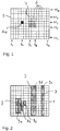
- Fig. 1 shows a plan view of a surface sensor 1 of an image recording unit 2 according to the invention in a highly schematic and simplified representation, which is used in particular to explain the terms and reference numerals used herein. Essentially, the photosensitive, rectangular surface of the area sensor 1 is shown. A representation of the other components of the area sensor 1 has been omitted for reasons of clarity. The construction and the technical functioning of such sensors are known to the person skilled in the art.
- a plurality of individually readable pixel elements 6 are arranged in a grid of sensor rows 5 and sensor columns 10 on the light-sensitive surface of the area sensor 1.
- the area sensor 1 comprises “n” sensor rows 5 and “m” sensor columns 10.
- the number n and the number m can be freely selected according to the usual sensor sizes or matched to the case in question.
- Area sensors frequently used in the industrial sector are, for example, in the 4: 3 format, for example in the resolutions nxm of 640 x 480, 1280 x 960, 1600 x 1200, etc., but also in other dimensions, for example in the 1: 1, 3: 2 formats , 5: 4, 6: 9 or other special formats with different number of pixels, from less than one megapixel to special formats with several thousand megapixels, available on the market or producible.
- Each individual sensor row 5 can be uniquely identified by a number x between 1 and n and each sensor column 10 can be uniquely identified by a number y between 1 and m.
- this is exemplified by the reference numerals of Sensor rows 5 1 , 5 p , 5 x , 5 q and 5 n , and the reference numerals of the sensor columns 10 1 , 10 r , 10 y , 10 s and 10 m are shown.
- each pixel element 6 can also be uniquely identified with the numbers of a specific sensor row 5 x and a specific sensor column 10 y , as shown, for example, in FIG Fig. 1 is represented by the sensor element 6 xy .
- Each pixel element 6 can either have an individual light sensor or a cooperating group of light sensors, for example for different spectral ranges.
- the present invention is based, among other things, on a definition of areas of the area sensor, such as that in FIG Fig. 1 Rectangular pixel area 7 shown.
- the pixel area 7 can comprise any partial selection of all pixel elements 6 xy .
- the definition in the case of a rectangular pixel area 7 is given, for example, by specifying an initial sensor line 5 p , an end sensor line 5 q , an initial sensor column 10 r and an end sensor column can be clearly defined for 10 s .
- a pixel area 7 does not necessarily have to have a rectangular, coherent shape, but it can also be composed of any combination of rectangular pixel partial areas 9, as is shown in FIG Fig. 2 is explained.
- the illustrated pixel area 7 comprises the three contiguous, respectively rectangular pixel partial areas 9a, 9b and 9c, as well as the two pixel partial areas 9d and 9e separated therefrom.
- the two last-mentioned pixel subregions 9d and 9e each extend over the entire line length, ie across all sensor columns 10 1 to 10 m .
- the pixel arrangement of the area sensors 1 described here is based in each case on a “classic”, checkerboard-like pixel geometry in which all the pixel elements have the same size (for example in the sense of a conventional Bayer matrix).
- Such an arrangement is the basis for most of the area sensors available on the market, but there are also alternative layouts in which pixel elements of different sizes can be provided (for example in the arrangement called "X-Trans-Matrix"), or in which the pixel elements are in one form deviating from the checkerboard pattern, for example in groups of five or diagonally.
- the definition of the pixel area 7 must be adapted accordingly, which is within the ability of an average person skilled in the art.
- the area sensor 1 has a multiplicity of sensor rows 5, each sensor row 5 comprises a plurality of preferably linearly arranged, individually readable pixel elements 6.
- the image recording unit 2 can be focused on objects 4 that are located in a recording area 11. The focusing can be carried out in a known manner by adjusting a lens arrangement arranged in the optics 3 and / or by arranging the image recording unit 2 at a distance selected accordingly from the objects 4 to be recorded.
- the values recorded by the pixel elements 6 of the area sensor 1 can be read out with the control unit 8.
- the surface sensor 1 is arranged directly on the control unit 8.
- a pixel area 7 comprising at least a partial area of the area sensor 1 can be defined, the control unit 8 restricting the reading of the area sensor 1 exclusively to the pixel elements 6 in the pixel area 7.
- the pixel area 7 can in particular in connection with 1 and 2 Forms described are defined, the definition may preferably include any subgroup from the totality of the pixel elements 6 provided on the area sensor 1. Alternatively, for example to simplify the parameterization, the definable pixel area 7 can be restricted to certain pixel groups.
- control unit 8 can use any desired selection of complete sensor lines 5 to define the pixel area 7, which simplifies the parameterization and enables the use of, for example, area sensors with line-based reading, such as CCD sensors.
- Each sensor line 5 (or each group of adjoining sensor lines 5) of the pixel area 7 can represent a kind of “linear sensor”, which is oriented in a defined direction towards the recording area 11.
- the possible definition of the pixel area 7 can also be limited to partial sections of the sensor line, for example to an “upper” or “lower” half of a sensor line 5, or the like.
- control unit 8 Since the control unit 8 does not have to read out the entirety of all the pixel elements 6 of the area sensor 1, but rather only processes the pixel elements 6 within the pixel regions 7, the amount of data to be processed and possibly forwarded can be considerably reduced, which can be used, for example, to increase the recording frequency can.
- the pixel area 7 can either be defined directly by the control unit 8 provided in the image recording unit 2 on the basis of defined algorithms, or it can be based on parameters that are transmitted via an interface 12 from an external control device 13.
- the interface 12 can comprise, for example, an industrial bus system.
- the control device can be, for example, a computer programmed with a corresponding software or a programmable logic controller (PLC) or another automation component.
- PLC programmable logic controller
- the Integrate image acquisition unit 2 in industrial applications If necessary, the interface 12 can communicate via the bus system, which is also used by the automation component for the control of other system parts.
- the pixel area 7 can either be immutably defined for a specific application, but it can also be dynamic, i.e. can be changed within a specific measurement task, as a result of which numerous advantageous methods can be carried out, which are described below.
- pixel areas 7 are shown by way of example, which are identified as pixel areas 7 ', 7 "and 7"' for differentiation with corresponding top lines.
- Each pixel region 7 ', 7 ", 7"' in this case, all pixel elements 6 comprises a sensor line 5, in particular comprising the first pixel region 7 ', the pixel elements 6 of the first sensor line 5 1, the third pixel area 7 "' includes the pixel elements of the last row of sensors 5 n and the second pixel area 7 "comprise the pixel elements 6 of an intermediate sensor line 5 x .
- the dimensions of the surface sensor 1 on the one hand and the dimensions, properties and relative alignment of the optics 3 on the other hand define the recording area 11 for the image recording unit 2, the optics 3 being focused on a specific measuring plane 15 and an essentially rectangular measuring region in this measuring plane 15 Are defined. With a corresponding depth of field, areas can also be detected with sufficient accuracy, if any, which are arranged above the measurement plane 15 (ie closer to the optics 3) and below the measurement plane 15. Each pixel area 7 ', 7 ", 7"' defines a corresponding image area 14 ', 14 ", 14"' in the measurement plane 15, which is recorded by the pixel elements 6 in the respective pixel area 7 ', 7 ", 7"'.
- Image areas 14 near the edge in particular can be subject to distortion due to imaging errors, in particular the distortion of the optics 3, which may be taken into account by the control unit 8 (or the external control device 13) and / or can be calculated out.
- the (linear) pixel areas 7 ', 7 ", 7"' each define a linear sensor, the image areas 14 ', 14 ", 14"' of these linear sensors each being oriented at a different angle to the measurement plane 15. This is particularly relevant in connection with an illumination of the measurement level 15.
- a lighting unit 16 is shown as an example, which illuminates the measurement plane 15 at a flat angle in the manner of dark field lighting.
- the illumination device 16 can optionally be synchronized with the recording frequency of the image recording unit 2.
- features on an object 4 for example a notch 17 or a scratch on the surface thereof, each have a different reflection behavior depending on the position of the image area 14 ', 14 ", 14"' when illuminated by the illumination unit 16.
- the Notch 17 recorded by the image recording unit 2 with a different contrast, depending on the position at which the object 4 is located.
- An analogous procedure can also be used advantageously for bright field lighting or for transmitted light images. For example, instead of the flat dark field illumination by the illumination unit 16, an (LED) ring lamp could be used, which is arranged around the optics 3 and illuminates the measuring surface 15 from the image acquisition unit 2.
- an optimal measurement position In addition to the determination of an optimal measurement position described above, more complex methods can also be carried out by the image recording unit 2 according to the invention. For example, it is possible to use the different recording directions that can be generated with the (fixed) image recording unit 2 to scan surfaces of moving objects, as is explained with reference to FIG Fig. 4 is explained.
- An object 4 moves, for example, linearly and at a known speed through the recording area 11, with successive positions of the object 4 in Fig. 4 are identified by the reference numerals 4 ', 4 ", 4"' and 4 "". At the first position (object 4 '), the object enters the recording area 11.
- the pixel area 7 is in the form of a by the external control device 13 or by the control unit 8 Line sensor set to the first sensor line 5 1 . While the object is moving through the recording area 11, the pixel area 7 is also changed such that the corresponding image area 14 is also moved with the object 4, but at a lower speed than the object 4. The pixel area 7 becomes over the entire recording time changed dynamically so that the last image area 14 "" detects the rear end of the object 4 "" at the point in time at which the object 4 leaves the recording area 11.
- the individual images that were recorded in the respective successive pixel regions 7 can be combined to form an overall image of the surface of the object.
- the front and back can also be fully reproduced due to the shooting angle, which is not possible with a snapshot.
- the image of the front and back would be distorted compared to the image of the flat surface, but this distortion can be determined by known arithmetic methods and, if necessary, calculated from an overall representation of the image.
- FIG. 5 Another example of a method which can be carried out with the image recording unit 2 according to the invention is shown in Fig. 5 shown schematically.
- the pixel area 7 (shown in the positions 7 ', 7 ", 7"') is in turn dynamically aligned with an object 4 (positions 4 ', 4 ", 4"') as it moves through the recording area 11.
- the pixel area 7 ', 7 ", 7"' always comprises several sensor rows 5, so that an image matrix is generated with each individual image.
- the speed at which the pixel region 7 is moved is matched to the speed of the object 4 such that the same part of the object 4 (in this case the front, upper edge) is essentially in the center of the corresponding image region 14 ', 13 ", 14"'. Since the same area of the object 4 was thus recorded from different viewing directions, a 3D model of the monitored area or of the entire object 4 can be created by comparing the recordings without the image recording unit 2 having to be moved or pivoted for this purpose.
- Fig. 6 shows a further example of an advantageous method according to the invention, which can be carried out with the image recording unit 2.
- the surfaces of objects 4 are to be scanned with the image recording unit 2, for example in order to identify product or production errors, scratches, damage or the like.
- the usual procedure is to stop each individual object 4 in a defined position in front of a linear scanner and to allow the object 4 to rotate about its axis in this position, so that the linear scanner scans the entire circumference of the object 4 with the linear scanner can.
- This method is not only a challenge for the transport device and the control, but is also very slow and inflexible, since a changeover to objects of a different shape generally requires a redesign of at least the entire measuring arrangement, with the lighting additionally having to be specifically adapted.
- the image recording unit 2 shown with its recording area 11 is aligned with a part of a transport or movement path through which a large number of objects 4 are transported or move through the recording area 11 in another way.
- the objects 4 move along a curved trajectory 17 and additionally rotate about an axis that is normal to the image plane.
- the path curve can, for example, be through a conveyor belt in a production, filling or packaging system and the objects can be, for example, semi-finished or finished products, packaging containers, such as bottles, boxes, pouch packaging, packages or the like.
- Each object 4 can have, for example, a reference feature 18, wherein the reference feature 18 can be, for example, a label, a trademark formed, for example, as a relief or another product or packaging feature present on each object 4.
- the reference feature 18 is not absolutely necessary, but can facilitate the regulation.
- the recording area 11 can be illuminated with any type of bright or dark field lighting that is suitable for the respective case, wherein in Fig. 6 an LED ring lamp is provided as the lighting device 16, which is arranged around the lens or the optics 3 of the image recording unit 2 and illuminates the entire recording area 11.
- the movement of the objects along the path curve 17 can optionally be monitored and / or controlled by the central control device 13 (for example a PLC or another automation unit), which also controls the image recording unit 2, but other regulation or control structures can also be provided .
- the central control device 13 transmits parameters to the image recording unit 2 via the interface 12.
- the image recording unit 2 sets a corresponding pixel area 7 on the basis of these parameters dynamically fixed, reads the measured values determined by the respective pixel elements 6 in the pixel area 7 according to the parameters and transmits the corresponding sensor data back to the central control device 13.
- the transmission can preferably be transmitted via the same interface 12 or in another way.
- the pixel area 7 simultaneously comprises several pixel sub-areas 9a-9f, each pixel sub-area 9a-9f being assigned to a specific object 4.
- the pixel area 7 is changed essentially in real time so that each pixel partial area 9a-9f (or the measuring area 14a-14f generated by this pixel partial area 9a-9f) is aligned with the object 4 assigned to it, from the point in time at which this Object 4 enters the receiving area 11 until the time when the object 4 leaves the receiving area 11.
- the objects 4 can also be scanned only in a smaller subinterval of the recording area 11.
- Each pixel subarea 9a-9f can, for example, be designed as a linear sensor and comprise one or more adjoining sensor lines 5 of the area sensor 1 of the image recording unit 2, for example as has already been described in connection with the previously described embodiments.
- each object 4 also performs a rotation about its own axis in addition to the translational movement along the path curve 17, it is possible by means of a correspondingly quick and precise adjustment of the pixel partial regions 9a-9f to essentially completely record the outer surface of each object 4 while it is inside of the receiving area 11 rotates.
- the reference feature 18 can be used to recognize an alignment of the object 4 or to generate reference measurements with which, for example, the illumination and the exact alignment of the measurement areas 14 can be optimized. In the case of essentially cylindrical objects, it is possible, for example, to always align the measuring region 14 with the moving object 4 in such a way that the measurement of the entire cylindrical surface takes place essentially at a constant surface angle.
- the image recording unit 2 can additionally take complete pictures of the entire recording area 11 at certain intervals, for example in order to optimize the alignment of the measurement areas 14 or to generate additional measurement data.
- the image recording unit 2 can additionally take complete pictures of the entire recording area 11 at certain intervals, for example in order to optimize the alignment of the measurement areas 14 or to generate additional measurement data.
- An analysis of this film recording can then be used to create and implement an optimal strategy for controlling the measuring areas 14.
- the respective static or dynamic pixel areas 7 can be defined either by the control unit 8 of the image recording unit 2 or by a central control device or by means of distributed roles.
- the central control device can control the definition of the pixel areas 7 and other functions of the image recording unit 2, for example by transmitting parameters.
- parameters that contain a direct definition of the pixel area 7 that is, the number, shape and size of the pixel subareas
- parameters that enable the control unit 8 to determine a pixel area 7, that is to say, for example, an indication of the position of an area which an image area 14 is to be directed parameters which define a recording frequency, parameters which define an exposure duration, parameters which relate to focusing, parameters which define a recording duration for a specific pixel area configuration and parameters which relate to the generation of the output data (eg creating an image of the "rolled" object 4 based on the images of a moving pixel sub-area, creating a 3d model of an object, etc.).
- the image recording unit 2 can also be used advantageously in other areas, for example for monitoring any objects, the functionality of the definition of pixel areas 7 being able to be combined in any way with the recording capabilities of the entire area sensor. For example, it is possible to continuously film a recording area 11 (possibly with a low recording frequency or with only a few pixels distributed via the area sensor 1) and to detect movements, for example, by determining difference images. When certain movement patterns are detected, a certain sequence of recordings with static or dynamic pixel areas 7 can then be triggered.
- the method steps disclosed in the description and the claims can be defined in a program logic executable by the control unit 8 of the image recording unit 2 and / or by the external control device 13, the program logic executed by the control unit 8 or the external control device 13 controlling the control unit 8 or enables the external control device 13 to carry out the corresponding method steps.
Landscapes
- Engineering & Computer Science (AREA)
- Signal Processing (AREA)
- Multimedia (AREA)
- General Physics & Mathematics (AREA)
- Physics & Mathematics (AREA)
- Analytical Chemistry (AREA)
- Immunology (AREA)
- Chemical & Material Sciences (AREA)
- Health & Medical Sciences (AREA)
- Biochemistry (AREA)
- General Health & Medical Sciences (AREA)
- Pathology (AREA)
- Life Sciences & Earth Sciences (AREA)
- Computer Vision & Pattern Recognition (AREA)
- Image Input (AREA)
- Studio Devices (AREA)
- Theoretical Computer Science (AREA)
- Length Measuring Devices By Optical Means (AREA)
- Transforming Light Signals Into Electric Signals (AREA)
Priority Applications (6)
| Application Number | Priority Date | Filing Date | Title |
|---|---|---|---|
| EP18208542.3A EP3661191A1 (fr) | 2018-11-27 | 2018-11-27 | Procédé de lecture d'un capteur de superficie |
| JP2019206635A JP2020088859A (ja) | 2018-11-27 | 2019-11-15 | エリアセンサを読み取るための方法 |
| CA3062237A CA3062237A1 (fr) | 2018-11-27 | 2019-11-21 | Methode de lecture d`un capteur d`images |
| CN201911172573.1A CN111225141B (zh) | 2018-11-27 | 2019-11-26 | 用于读取图像传感器的方法 |
| US16/695,376 US11442022B2 (en) | 2018-11-27 | 2019-11-26 | Method for reading an image sensor |
| KR1020190154053A KR20200064002A (ko) | 2018-11-27 | 2019-11-27 | 이미지 센서 판독 방법 |
Applications Claiming Priority (1)
| Application Number | Priority Date | Filing Date | Title |
|---|---|---|---|
| EP18208542.3A EP3661191A1 (fr) | 2018-11-27 | 2018-11-27 | Procédé de lecture d'un capteur de superficie |
Publications (1)
| Publication Number | Publication Date |
|---|---|
| EP3661191A1 true EP3661191A1 (fr) | 2020-06-03 |
Family
ID=64606705
Family Applications (1)
| Application Number | Title | Priority Date | Filing Date |
|---|---|---|---|
| EP18208542.3A Ceased EP3661191A1 (fr) | 2018-11-27 | 2018-11-27 | Procédé de lecture d'un capteur de superficie |
Country Status (6)
| Country | Link |
|---|---|
| US (1) | US11442022B2 (fr) |
| EP (1) | EP3661191A1 (fr) |
| JP (1) | JP2020088859A (fr) |
| KR (1) | KR20200064002A (fr) |
| CN (1) | CN111225141B (fr) |
| CA (1) | CA3062237A1 (fr) |
Citations (5)
| Publication number | Priority date | Publication date | Assignee | Title |
|---|---|---|---|---|
| DE102009006112A1 (de) | 2008-02-01 | 2009-08-06 | Austrian Research Centers Gmbh - Arc | Verfahren und Vorrichtung zum Prüfen von Lumineszenzfarbmuster tragenden Gegenständen |
| EP2600605A1 (fr) * | 2011-11-30 | 2013-06-05 | AIT Austrian Institute of Technology GmbH | Procédé et dispositif de réception pour la réception d'images à spectres multiples |
| DE102013223852A1 (de) * | 2013-11-21 | 2015-05-21 | Robert Bosch Gmbh | Verfahren zur Erstellung von mindestens zwei Bildern mit einer Kameravorrichtung sowie Kameravorrichtung |
| EP2903264A1 (fr) | 2014-01-31 | 2015-08-05 | AIT Austrian Institute of Technology GmbH | Procédé de détermination du champ lumineux d'un objet |
| US9716847B1 (en) * | 2012-09-25 | 2017-07-25 | Google Inc. | Image capture device with angled image sensor |
Family Cites Families (6)
| Publication number | Priority date | Publication date | Assignee | Title |
|---|---|---|---|---|
| US8803978B2 (en) * | 2006-05-23 | 2014-08-12 | Microsoft Corporation | Computer vision-based object tracking system |
| JP5932376B2 (ja) * | 2012-02-08 | 2016-06-08 | 富士機械製造株式会社 | 画像転送方法および画像転送装置 |
| JP2015216482A (ja) * | 2014-05-09 | 2015-12-03 | キヤノン株式会社 | 撮像制御方法、および撮像装置 |
| DE102016220757A1 (de) * | 2016-10-21 | 2018-04-26 | Texmag Gmbh Vertriebsgesellschaft | Verfahren und Vorrichtung zur Materialbahnbeobachtung und Materialbahninspektion |
| JP6987513B2 (ja) * | 2017-03-07 | 2022-01-05 | ソニー・オリンパスメディカルソリューションズ株式会社 | 内視鏡装置 |
| DE102019004233B4 (de) * | 2018-06-15 | 2022-09-22 | Mako Surgical Corp. | Systeme und verfahren zum verfolgen von objekten |
-
2018
- 2018-11-27 EP EP18208542.3A patent/EP3661191A1/fr not_active Ceased
-
2019
- 2019-11-15 JP JP2019206635A patent/JP2020088859A/ja active Pending
- 2019-11-21 CA CA3062237A patent/CA3062237A1/fr active Pending
- 2019-11-26 US US16/695,376 patent/US11442022B2/en active Active
- 2019-11-26 CN CN201911172573.1A patent/CN111225141B/zh active Active
- 2019-11-27 KR KR1020190154053A patent/KR20200064002A/ko not_active Withdrawn
Patent Citations (5)
| Publication number | Priority date | Publication date | Assignee | Title |
|---|---|---|---|---|
| DE102009006112A1 (de) | 2008-02-01 | 2009-08-06 | Austrian Research Centers Gmbh - Arc | Verfahren und Vorrichtung zum Prüfen von Lumineszenzfarbmuster tragenden Gegenständen |
| EP2600605A1 (fr) * | 2011-11-30 | 2013-06-05 | AIT Austrian Institute of Technology GmbH | Procédé et dispositif de réception pour la réception d'images à spectres multiples |
| US9716847B1 (en) * | 2012-09-25 | 2017-07-25 | Google Inc. | Image capture device with angled image sensor |
| DE102013223852A1 (de) * | 2013-11-21 | 2015-05-21 | Robert Bosch Gmbh | Verfahren zur Erstellung von mindestens zwei Bildern mit einer Kameravorrichtung sowie Kameravorrichtung |
| EP2903264A1 (fr) | 2014-01-31 | 2015-08-05 | AIT Austrian Institute of Technology GmbH | Procédé de détermination du champ lumineux d'un objet |
Non-Patent Citations (1)
| Title |
|---|
| SCHREY O ET AL: "A 1K X 1K HIGH DYNAMIC RANGE CMOS IMAGE SENSOR WITH ON-CHIP PROGRAMMABLE REGION-OF-INTEREST READOUT", IEEE JOURNAL OF SOLID-STATE CIRCUITS, IEEE SERVICE CENTER, PISCATAWAY, NJ, USA, vol. 37, no. 7, 1 July 2002 (2002-07-01), pages 911 - 915, XP001221315, ISSN: 0018-9200, DOI: 10.1109/JSSC.2002.1015690 * |
Also Published As
| Publication number | Publication date |
|---|---|
| KR20200064002A (ko) | 2020-06-05 |
| CN111225141A (zh) | 2020-06-02 |
| JP2020088859A (ja) | 2020-06-04 |
| US20200167895A1 (en) | 2020-05-28 |
| CA3062237A1 (fr) | 2020-05-27 |
| CN111225141B (zh) | 2023-07-07 |
| US11442022B2 (en) | 2022-09-13 |
Similar Documents
| Publication | Publication Date | Title |
|---|---|---|
| DE69515646T2 (de) | Verfahren und Vorrichtung zum Erfassen von Fehlern in Textilbahnen und dergleichen | |
| DE69723799T2 (de) | Vorrichtung zur Bildaufnahme und Bildverarbeitung | |
| DE69929901T2 (de) | Inspektionssystem für die oberfläche von zylindrischen objekten | |
| EP3022145B1 (fr) | Appareil et procédé de codage et de détermination de la position | |
| EP2865987B1 (fr) | Procédé et scanner destinés à la détermination sans contact de la position et de la forme tridimensionnelle de produits sur une surface déroulante | |
| DE102013212495A1 (de) | Verfahren und Vorrichtung zur Inspektion einer konturierten Fläche,insbesondere des Unterbodens eines Kraftfahrzeugs | |
| EP3346230A1 (fr) | Dispositif et procede de mesure de la courbure d'un fil | |
| EP2589926B1 (fr) | Dispositif et procédé de mesure optique de la forme d'un objet mobile | |
| DE102013105214A1 (de) | Untersuchungsverfahren eines Produkts in einer Verpackungsmaschine | |
| WO2016146105A1 (fr) | Procédé et dispositif d'étalonnage d'une caméra | |
| DE3809221A1 (de) | Verfahren zum detektieren von fehlstellen an pressteilen oder anderen werkstuecken und vorrichtung zur durchfuehrung des verfahrens | |
| EP4402429A1 (fr) | Procédé et dispositif de mesure d'informations de profondeur d'une scène au moyen d'une lumière structurée générée au moyen d'au moins une source de rayonnement parallèle | |
| DE102018220271A1 (de) | Optische Aufnahmevorrichtung und Verfahren zur optischen Aufnahme | |
| DE69915655T2 (de) | Apparat zur abbildung und zur inspektion der oberfläche von dreidimensionalen objekten | |
| EP2208987B1 (fr) | Procédé et installation d'inspection de surface visuelle | |
| EP1543471B1 (fr) | Detection et prise d'objets | |
| DE102009017465B4 (de) | Verfahren und Vorrichtung zum optischen Inspizieren einer zumindest teilweise reflektierenden Oberfläche an einem Gegenstand | |
| EP3247990A1 (fr) | Procédé et dispositif de détermination de l'effet de substances actives sur des nématodes et d'autres organismes dans des tests aqueux | |
| WO2019185184A1 (fr) | Dispositif et procédé pour la détection optique de position d'objets transportés | |
| DE102013105216A1 (de) | Untersuchungsverfahren eines Produkts in einer Verpackungsmaschine | |
| EP3510877B1 (fr) | Dispositif et procédé de vérification des articles en forme de boudin de l'industrie de traitement du tabac | |
| DE102017009153B4 (de) | Anordnung und Verfahren zur Inspektion von bewegten plattenförmigen Objekten | |
| DE102013223852B4 (de) | Verfahren zur Erstellung von mindestens zwei Bildern mit einer Kameravorrichtung sowie Kameravorrichtung | |
| WO2015043978A1 (fr) | Mesure de châssis en présence de lumière ambiante | |
| DE102011116791B4 (de) | Optisches Prüfverfahren mit Mehrfach-Auslesung/Einfrieren |
Legal Events
| Date | Code | Title | Description |
|---|---|---|---|
| PUAI | Public reference made under article 153(3) epc to a published international application that has entered the european phase |
Free format text: ORIGINAL CODE: 0009012 |
|
| STAA | Information on the status of an ep patent application or granted ep patent |
Free format text: STATUS: THE APPLICATION HAS BEEN PUBLISHED |
|
| AK | Designated contracting states |
Kind code of ref document: A1 Designated state(s): AL AT BE BG CH CY CZ DE DK EE ES FI FR GB GR HR HU IE IS IT LI LT LU LV MC MK MT NL NO PL PT RO RS SE SI SK SM TR |
|
| AX | Request for extension of the european patent |
Extension state: BA ME |
|
| STAA | Information on the status of an ep patent application or granted ep patent |
Free format text: STATUS: REQUEST FOR EXAMINATION WAS MADE |
|
| 17P | Request for examination filed |
Effective date: 20201130 |
|
| RBV | Designated contracting states (corrected) |
Designated state(s): AL AT BE BG CH CY CZ DE DK EE ES FI FR GB GR HR HU IE IS IT LI LT LU LV MC MK MT NL NO PL PT RO RS SE SI SK SM TR |
|
| STAA | Information on the status of an ep patent application or granted ep patent |
Free format text: STATUS: EXAMINATION IS IN PROGRESS |
|
| 17Q | First examination report despatched |
Effective date: 20211130 |
|
| STAA | Information on the status of an ep patent application or granted ep patent |
Free format text: STATUS: THE APPLICATION HAS BEEN REFUSED |
|
| 18R | Application refused |
Effective date: 20240826 |