EP3661261A1 - Verfahren zur detektion von downlink-steuerungsinformation, übertragungsverfahren, endgerät und netzwerkvorrichtung - Google Patents
Verfahren zur detektion von downlink-steuerungsinformation, übertragungsverfahren, endgerät und netzwerkvorrichtung Download PDFInfo
- Publication number
- EP3661261A1 EP3661261A1 EP18837603.2A EP18837603A EP3661261A1 EP 3661261 A1 EP3661261 A1 EP 3661261A1 EP 18837603 A EP18837603 A EP 18837603A EP 3661261 A1 EP3661261 A1 EP 3661261A1
- Authority
- EP
- European Patent Office
- Prior art keywords
- dci
- payload size
- terminal
- candidate
- information
- Prior art date
- Legal status (The legal status is an assumption and is not a legal conclusion. Google has not performed a legal analysis and makes no representation as to the accuracy of the status listed.)
- Granted
Links
Images


Classifications
-
- H—ELECTRICITY
- H04—ELECTRIC COMMUNICATION TECHNIQUE
- H04L—TRANSMISSION OF DIGITAL INFORMATION, e.g. TELEGRAPHIC COMMUNICATION
- H04L5/00—Arrangements affording multiple use of the transmission path
- H04L5/0091—Signalling for the administration of the divided path, e.g. signalling of configuration information
-
- H—ELECTRICITY
- H04—ELECTRIC COMMUNICATION TECHNIQUE
- H04L—TRANSMISSION OF DIGITAL INFORMATION, e.g. TELEGRAPHIC COMMUNICATION
- H04L1/00—Arrangements for detecting or preventing errors in the information received
- H04L1/0001—Systems modifying transmission characteristics according to link quality, e.g. power backoff
- H04L1/0036—Systems modifying transmission characteristics according to link quality, e.g. power backoff arrangements specific to the receiver
- H04L1/0038—Blind format detection
-
- H—ELECTRICITY
- H04—ELECTRIC COMMUNICATION TECHNIQUE
- H04L—TRANSMISSION OF DIGITAL INFORMATION, e.g. TELEGRAPHIC COMMUNICATION
- H04L1/00—Arrangements for detecting or preventing errors in the information received
- H04L1/004—Arrangements for detecting or preventing errors in the information received by using forward error control
- H04L1/0045—Arrangements at the receiver end
-
- H—ELECTRICITY
- H04—ELECTRIC COMMUNICATION TECHNIQUE
- H04L—TRANSMISSION OF DIGITAL INFORMATION, e.g. TELEGRAPHIC COMMUNICATION
- H04L1/00—Arrangements for detecting or preventing errors in the information received
- H04L1/004—Arrangements for detecting or preventing errors in the information received by using forward error control
- H04L1/0056—Systems characterized by the type of code used
- H04L1/0061—Error detection codes
-
- H—ELECTRICITY
- H04—ELECTRIC COMMUNICATION TECHNIQUE
- H04L—TRANSMISSION OF DIGITAL INFORMATION, e.g. TELEGRAPHIC COMMUNICATION
- H04L5/00—Arrangements affording multiple use of the transmission path
- H04L5/003—Arrangements for allocating sub-channels of the transmission path
- H04L5/0044—Allocation of payload; Allocation of data channels, e.g. PDSCH or PUSCH
-
- H—ELECTRICITY
- H04—ELECTRIC COMMUNICATION TECHNIQUE
- H04L—TRANSMISSION OF DIGITAL INFORMATION, e.g. TELEGRAPHIC COMMUNICATION
- H04L5/00—Arrangements affording multiple use of the transmission path
- H04L5/003—Arrangements for allocating sub-channels of the transmission path
- H04L5/0053—Allocation of signalling, i.e. of overhead other than pilot signals
-
- H—ELECTRICITY
- H04—ELECTRIC COMMUNICATION TECHNIQUE
- H04W—WIRELESS COMMUNICATION NETWORKS
- H04W72/00—Local resource management
- H04W72/20—Control channels or signalling for resource management
- H04W72/23—Control channels or signalling for resource management in the downlink direction of a wireless link, i.e. towards a terminal
Definitions
- the present disclosure relates to the field of communication technologies, and in particular, to a downlink control information detecting method, a downlink control information transmitting method, a terminal and a network device.
- LTE Long Term Evolution
- 5G fifth generation
- NR New Radio
- PDCCH physical downlink control channel
- CCE control channel elements
- DCI downlink control information
- the terminal blind detection refers to that the terminal finds a starting position of the CCE, and intercepts a guessed DCI length at the starting position of the CCE for decoding; if CRC of decoded information bits is the same as CRC carried in the PDCCH, determines that the information bits carried by the current PDCCH is downlink control information currently transmitted. Specifically, the terminal needs to determine which DCI format the PDCCH carries, and the terminal expects to obtain a certain DCI according to its current state.
- the terminal when the terminal is in an idle state, the terminal expects to receive paging system information (hereinafter referred to as SI); when the terminal needs to transmit uplink data, the terminal expects to receive an uplink grant (hereinafter referred to as UL Grant); after the terminal initiates a random access procedure, the terminal expects to receive a random access channel response (hereinafter referred to as RACH Response) and so on.
- SI paging system information
- UL Grant uplink grant
- RACH Response random access channel response
- the terminal needs to use the corresponding Radio Network Temporary Identity (hereinafter referred to as RNTI) to perform Cyclic Redundancy Check (hereinafter referred to as CRC) with CCE information. If the check succeeds, the terminal learns that the information is required by itself, and then further parses content of corresponding DCI according to the modulation and coding manner.
- CRC Cyclic Redundancy Check
- CCEs in the LTE system are divided into two search spaces, namely a common search space and a specific search space.
- Data transmitted in the common search space mainly includes system information (SI), Random Access Response (RAR), paging, and the like, and each terminal searches the common search space.
- SI system information
- RAR Random Access Response
- paging and the like
- each terminal searches the common search space.
- AL Aggregation Level
- the number of blind detections performed by the terminal include searching for 6 times in the common search space and searching for 16 times in the specific search space.
- the DCI format for the terminal at the same time has only two payload sizes, so the terminal needs to search twice, that is, 32 times.
- the DCI formats are more than that in the LTE system.
- the payload sizes of different DCI formats are quite different, and it is difficult to align payload sizes of different DCI formats to one or two types of payload sized by padding, which leads to high complexity of blind detection and an increase in the number of blind detections.
- an embodiment of the present disclosure provides a downlink control information detecting method, applied to a terminal, and including:
- an embodiment of the present disclosure provides a terminal including: a processor, a memory and a computer program stored on the memory and executable on the processor.
- the computer program is executed by the processor to implement steps of the above downlink control information detecting method.
- an embodiment of the present disclosure provides a computer readable storage medium including a computer program stored thereon.
- the computer program is executed by a processor to implement steps of the above downlink control information detecting method.
- an embodiment of the present disclosure provides a downlink control information transmitting method, applied to a network device, including:
- an embodiment of the present disclosure provides a network device including:
- an embodiment of the present disclosure provides a network device including: a processor, a memory and a computer program stored on the memory and executable on the processor.
- the computer program is executed by the processor to implement steps of the downlink control information transmitting method.
- an embodiment of the present disclosure provides a computer readable storage medium including a computer program stored thereon.
- the computer program is executed by a processor to implement steps of the downlink control information transmitting method.
- a downlink control information detecting method is applied to a terminal, and specifically includes the following steps: Step 11: obtaining indication information for indicating candidate downlink control information (DCI) payload size.
- Step 11 obtaining indication information for indicating candidate downlink control information (DCI) payload size.
- the DCI payload size refers to the size (bit number) of a padded DCI. This padding may be for the purpose of aligning different DCI sizes, or may be aligned according to the size of the network configuration.
- the indication information is used to indicate candidate DCI payload size, i.e., indicating probable DCI payload sizes.
- the candidate DCI payload size indicated by the indication information may be one DCI payload size or several DCI payload sizes.
- Step 12 according to the candidate DCI payload size indicated by the indication information, performing blind detection on a physical downlink control channel (PDCCH) and determining DCI transmitted on the PDCCH.
- PDCCH physical downlink control channel
- the terminal can learn the probable DCI payload size of current PDCCH transmission.
- the PDCCH is blindly checked according to probable DCI payload size of transmission, thereby determining DCI transmitted on the PDCCH.
- the blind detection is performed according to the candidate DCI payload size indicated by the indication information, and the blind detection is not performed according to all supported DCI payload sizes, which can reduce the number of blind detections and reduce the complexity of blind detections.
- the step 11 includes: receiving first indication information that is configured and transmitted by the network device.
- the first indication information is used to indicate at least one candidate DCI payload size corresponding to the terminal, or the first indication information is used to indicate at least one candidate DCI payload size corresponding to each control resource set of the terminal.
- the supported DCI formats are more than the DCI formats in the LTE system. Accordingly, DCI information bits supported by different DCI formats in the NR system may also increase. As shown in Fig. 2 , the DCI formats include: format 1C, format 1A-1, format 1A-2, format 2-1, format 2-2, format 0, format 3/3A, format xx, and format yy. The information bits of various DCI formats differ greatly.
- the network device may configure a set of candidate DCI payload sizes for each terminal, or the network device may configure a set of candidate DCI payload sizes for each control resource set (hereinafter referred to as CORESET) of each terminal. As shown in Fig.
- a candidate DCI payload size configured by the network device for CORESET1 of one terminal is 30 bits; candidate payload sizes configured by the network device for CORESET2 of the terminal include 50 bits and 60 bits; and, candidate payload sizes configured by the network device for CORESET3 of the terminal include 50 bits, 60 bits and 70 bits.
- CORESET is a set of time-frequency resources introduced in the NR system, that is, the terminal performs PDCCH detection in the corresponding CORESET.
- one or more CORESETs exist in a control region of one slot, and the terminal may detect PDCCH in one or more CORESETs.
- the PDCCH occupies one or more (for example, 1, 2, 4, and 8) CCEs for transmission, that is, mapping from PDCCH to the time-frequency resource is based on CCE structure.
- a basic resource unit of the CCE is a resource element group (hereinafter referred to as REG), and one CCE is composed of a certain number of REGs (i.e., composed of 6 REGs).
- CORESET is composed of a group of REGs.
- One REG is composed of one RB (i.e., 12 consecutive subcarriers) in the frequency domain and one Orthogonal Frequency Division Multiplexing (OFDM) symbol in the time domain.
- the time-frequency position configuration of the CORESET may be notified by one or more of the following combinations: time-frequency position configuration information of the CORESET may be notified by high-level signaling; or, the time-frequency position configuration information of the CORESET may be notified by broadcast channel and system information; the time-frequency position configuration information of the CORESET may be pre-defined based on one or more of information such as system bandwidth, subcarrier spacing, antenna configuration, and carrier frequency.
- the network device may configure candidate DCI payload sizes for different terminals by high layer signaling; accordingly, the terminal may receive, by the high layer signaling, the first indication information that is configured and transmitted by the network device.
- the network device and the terminal may determine one or more default DCI payload sizes corresponding to the terminal by means of predefined agreement, pre-configuration, or the like.
- the first indication information obtained by the terminal may further indicate at least one default DCI payload size.
- the default DCI payload size may be dynamically changed according to transmission scenario, transmission service, or the like, or defined by a standard.
- the candidate DCI payload size configured by the network device for the terminal may be invalid, and then, the terminal performs blind detection on the PDCCH according to the default DCI payload size, thereby preventing the problem of leak detection caused by performing blind detection according to the invalid candidate DCI payload size.
- the terminal blindly detects the PDCCH, in addition to performing blind detection according to the candidate DCI payload size configured by the network device, the terminal also needs to perform blind detection according to the default DCI payload size in a certain scenario, thereby ensuring the accuracy of PDCCH blind detection.
- step 12 in the embodiment of the present disclosure may be specifically implemented by performing the following steps: performing blind detection on the PDCCH according to the candidate DCI payload size indicated by the indication information, thereby obtaining a bit string; parsing indication field in the bit string, and determining DCI format of DCI transmitted in the PDCCH according to a parsed result; and parsing the DCI carried in the bit string according to the DCI format.
- the DCI transmitted by the network device is transmitted after being padded to a certain DCI payload size, thus, when parsing the DCI, the terminal needs to adopt an additional mechanism to recover original DCI, thereby obtaining an actual DCI format of the DCI and then learning corresponding information bits of the actual DCI format.
- an additional mechanism is required to detect valid bits of the bit string.
- the indication field includes a specific target field and a Cyclic Redundancy Check (CRC) field.
- CRC Cyclic Redundancy Check
- the step of parsing indication field in the bit string and determining DCI format of DCI transmitted in the PDCCH according to a parsed result may be implemented in the following modes.
- Mode 1 parsing a specific target field in the bit string, and determining DCI format of DCI transmitted in the PDCCH according to a parsed result.
- the specific target field is a certain field in the DCI.
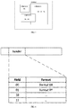
- the specific target field may be configured at a header position of the DCI, and then the specific target field may be referred to as header field.
- the terminal After the terminal performs blind detection on PDCCH according to the candidate DCI payload size indicated by the indication information, the terminal determines DCI payload size of the DCI and then obtains a decoded bit string by decoding. Then, format of the DCI is learn through the header field, thereby obtaining corresponding information bits of the DCI format.
- the header field is used to indicate the format of the DCI. Specifically, as shown in Fig. 4 , when the header field is 00, it indicates that the DCI format is format xx; and, when the header field is 01, it indicates that the DCI format is format yy.
- Mode 2 descrambling the CRC field in the bit string by means of cyclic redundancy check (CRC), and determining DCI format of DCI transmitted in the PDCCH according to a descrambling result.
- CRC cyclic redundancy check
- the extra information of the DCI format can be carried by scrambling, by the network device, the CRC field in the DCI.
- the terminal After the terminal performs blind detection on PDCCH according to the candidate DCI payload size indicated by the indication information, the terminal determines DCI payload size of the DCI and then obtains a decoded bit string by decoding. Then, format of the DCI is learn by descrambling the CRC field in the bit string, thereby obtaining corresponding information bits of the DCI format. As shown in Fig. 5 , when the descrambling CRC field is 00000000, it indicates that the DCI format is format xx; and, when he descrambling CRC field is 11111111, it indicates that the DCI format is format yy.
- Mode 3 descrambling the CRC field in the bit string by means of cyclic redundancy check (CRC), and determining DCI format of DCI transmitted in the PDCCH according to a descrambling result; further, parsing a specific target field in the bit string and determining whether DCI format is correct according to a parsed result.
- CRC cyclic redundancy check
- This mode is a first one of combination modes of the first mode and the second mode, and determines the DCI format by means of descrambling the CRC field supplemented by the header field.
- different DCI formats are treated differently: when a difference between a DCI payload size and actual information bits of the transmitted DCI is insufficient to introduce an additional field (header), then, the additional field is not introduced; when a difference between a DCI payload size and actual information bits of the transmitted DCI is sufficient to introduce an additional field (header), then DCI includes the additional field (header) for the terminal to determine whether the DCI format is correct by cross-checking with the descrambling CRC.
- Mode 4 descrambling the CRC field in the bit string by means of cyclic redundancy check (CRC), determining whether the bit string includes the specific target field; when the bit string does not include the specific target field, determining that DCI format of DCI transmitted in the PDCCH is default DCI format; when the bit string includes the specific target field, parsing the specific target field in the bit string, and determining DCI format of DCI transmitted in the PDCCH according to a parsed result.
- CRC cyclic redundancy check
- This mode is a second one of combination modes of the mode 1 and mode 2, descrambles the CRC field to indicate whether an additional header field is introduced, and then the DCI format is determined with the additional header field. Specifically, after the terminal performs blind detection on PDCCH according to the candidate DCI payload size indicated by the indication information, the terminal determines DCI payload size of the DCI and then obtains a decoded bit string by decoding. Then, the CRC field in the bit string is descrambled, and information carried in the CRC field is used to determine whether the DCI includes an additional field (header) for indicating DCI format. When the information carried in the CRC field indicates that the DCI does not include an additional field, then the terminal receives according to the default DCI format. When the information carried in the CRC field indicates that the DCI includes an additional field for indicating the DCI format, the terminal reads the field to obtain the DCI format.
- Mode 5 parsing a specific target field in the bit string and descrambling the CRC field in the bit string by means of cyclic redundancy check (CRC), and determining DCI format of DCI transmitted in the PDCCH.
- CRC cyclic redundancy check
- This mode is a third one of combination modes of the mode 1 and mode 2, i.e., the DCI format is indicated by two types of fields, one type includes an additional field (header) introduced in DCI, and the other type includes CRC field.
- the DCI format is indicated by two types of fields, one type includes an additional field (header) introduced in DCI, and the other type includes CRC field.
- the step of parsing a specific target field in the bit string, and determining DCI format of DCI transmitted in the PDCCH according to a parsed result includes the following steps: obtaining a correspondence relationship between the candidate DCI payload size and the DCI format; determining indication field in the bit string according to the correspondence relationship; parsing the indication field and determining the DCI format of the DCI transmitted in the PDCCH according to the parsing result.
- the step of obtaining the correspondence relationship between the DCI payload size and the DCI format includes: obtaining first correspondence relationship information in a predefined manner.
- the first correspondence relationship information is used to indicate correspondence relationship between all candidate DCI payload sizes and DCI formats.
- This mode is an implicit indication mode, and the terminal can learn the correspondence relationship between all candidate DCI payload sizes and the DCI formats in a mode defined in a standard, or the terminal can receive the first correspondence information transmitted by the network device through system information, high layer signaling, etc., when the terminal accesses.
- the step of obtaining the correspondence relationship between the DCI payload size and the DCI format includes: receiving second correspondence information that is configured and transmitted by the network device.
- the second correspondence information is used to indicate a correspondence relationship between the candidate DCI payload size indicated by the indication information and the DCI format.
- the step of determining the indication field in the bit string according to the above correspondence relationship includes: according to the candidate DCI payload size indicated by the indication information, determining a first candidate DCI payload size of the DCI transmitted in the PDCCH; according to the correspondence relationship between the candidate DCI payload size and the DCI format, determining number information of first format corresponding to the first candidate DCI payload size; according to the number information, determining bit number of the indication field in the bit string.
- the network device determines a bit length of the header field according to the number of DCI formats corresponding to each DCI payload size.
- the header field may take values in the order from 0 according to configured DCI formats, or, the header field may take values in the order of information bit sizes in the DCI formats.
- An example is provided in the following table.
- DCI format Information bits size DCI payload size Header bit number Header field format 0 25 30 1-bit '0' format 1A -1 30 '1' format 1A -2 40 45 1-bit '0' format 3 35 '1' format 2 -1 50 60 1-bit '0' format 2 -2 60 '1'
- the DCI payload sizes in the table are set to three types including 30, 45, and 60.
- the information bit sizes of different DCI formats are different.
- the information bit size of format0 is 25 bits
- the information bit size of format 1A-1 is 30-bit.
- DCI payload sizes corresponding to format0 and format 1A-1 are 30 bits, then the 30-bit DCI payload size corresponds to two different DCI formats, and an additional 1-bit header field is required.
- the value of the header field is 0, it indicates that the DCI format is format0.
- the value of the header field is 1, it indicates that the DCI format is format 1A-1.
- the manner in which the CRC field indicates different DCI formats is similar to the manner in which the header field indicates the DCI format.
- the CRC field may take values in the order from 0 according to configured DCI formats, or, the CRC field may take values in the order of information bit sizes in the DCI formats.
- An example is provided in the following table.
- DCI format Information bits size DCI payload size CRC scrambling format 0 25 30 00000000 format 1A -1 30 00000001 format 1A -2 40 45 00000000 format 3 35 00000001 format 2 -1 50 60 00000000 format 2 -2 60 00000001
- the DCI payload sizes in the table are set to three types including 30, 45, and 60.
- the information bit sizes of different DCI formats are different.
- the information bit size of format0 is 25 bits
- the information bit size of format 1A-1 is 30-bits.
- DCI payload sizes corresponding to format0 and format 1A-1 are 30 bits, then the 30-bit DCI payload size corresponds to two different DCI formats.
- the value of the CRC field is 00000000, it indicates that the DCI format is format0.
- the value of the CRC field is 00000001, it indicates that the DCI format is format 1A-1.
- the indication field may also be a predefined header field and/or a CRC field. That is, values of the header field and/or the CRC field correspond to different DCI formats.
- the correspondence relationship may be predefined in the protocol, or may be configured by the network device for the terminal.
- the terminal obtains the indication information for indicating the candidate DCI payload size, and performs blind detection on the PDCCH according to the candidate DCI payload size, thereby reducing blind detection number and reducing the blind detection complexity.
- the terminal 600 of the embodiment of the present disclosure can implement details of the method in the above embodiment and achieve the same effects, i.e., obtaining the indication information for indicating the DCI payload size of the candidate downlink control information, performing blind detection on the PDCCH according to the candidate DCI payload size indicated by the indication information, and determining DCI transmitted in the PDCCH.
- the terminal 600 specifically includes the following functional modules.
- a first obtaining module 610 is used to obtain indication information for indicating candidate downlink control information (DCI) payload size.
- DCI downlink control information
- a processing module 620 is used to perform blind detection on a physical downlink control channel (PDCCH) according to the candidate DCI payload size indicated by the indication information, and determine DCI transmitted on the PDCCH.
- PDCCH physical downlink control channel
- the first obtaining module 610 includes: a first receiving submodule, used to receive first indication information that is configured and transmitted by the network device.
- the first indication information is used to indicate at least one candidate DCI payload size corresponding to the terminal, or the first indication information is used to indicate at least one candidate DCI payload size corresponding to each control resource set of the terminal.
- the first receiving submodule is specifically used to, receive, by high layer signaling, the first indication information that is configured and transmitted by the network device.
- the first indication information is used to indicate at least one default DCI payload size.
- the processing module 620 includes:
- the processing submodule includes: a first processing unit used to parse a specific target field in the bit string, and determine DCI format of the DCI transmitted in the PDCCH according to a parsing result.
- the processing submodule includes: a second processing unit used to descramble the CRC field in the bit string by means of cyclic redundancy check (CRC), and determine DCI format of DCI transmitted in the PDCCH according to a descrambling result.
- CRC cyclic redundancy check
- the processing submodule further includes: a first parsing unit, used to parse a specific target field in the bit string, and determine whether the DCI format is correct according to a parsing result.
- the parsing submodule includes: a second parsing unit used to parse the DCI carried in the bit string according to the DCI format when determining that the DCI format is correct according to the parsing result.
- the processing submodule includes:
- the processing submodule includes: a fifth processing unit, used to parse the specific target field in the bit string and descramble the CRC field in the bit string by means of cyclic redundancy check (CRC), and determine the DCI format of DCI transmitted in the PDCCH.
- a fifth processing unit used to parse the specific target field in the bit string and descramble the CRC field in the bit string by means of cyclic redundancy check (CRC), and determine the DCI format of DCI transmitted in the PDCCH.
- CRC cyclic redundancy check
- the terminal 600 further includes:
- the second obtaining module includes:
- the terminal 600 further includes:
- the terminal in the embodiment of the present disclosure obtains the indication information for indicating the candidate DCI payload size, and performs blind detection on the PDCCH according to the candidate DCI payload size, thereby reducing the number of blind detection and reduce the blind detection complexity.
- an embodiment of the present disclosure further provides a terminal, including a processor, a memory, and a computer program stored on the memory and executable on the processor.
- the processor implements the computer program to implement steps in the above downlink control information detecting method.
- An embodiment of the present disclosure further provides a computer readable storage medium including a computer program stored thereon. The computer program is executed by a processor to implement the steps of the downlink control information detecting method as described above.
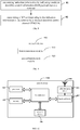
- Fig. 7 is a block diagram of a terminal 700 of another embodiment of the present disclosure.
- the terminal includes at least one processor 701, a memory 702, a user interface 703, and a network interface 704.
- the various components in the terminal 700 are coupled together by a bus system 705.
- the bus system 705 is used to implement connection communication between these components.
- the bus system 705 includes a power bus, a control bus, and a status signal bus in addition to the data bus.
- various buses are labeled as the bus system 705 in Fig. 7 .
- the user interface 703 may include a display device or a clicking device (i.e., a touchpad or a touch screen).
- the memory 702 in an embodiment of the present disclosure may be a volatile memory or a non-volatile memory, or may include both volatile memory and non-volatile memory.
- the non-volatile memory may be a read-only memory (ROM), a programmable read only memory (PROM), an erasable PROM (EPROM), or an electrically EPROM (EEPROM) or flash memory.
- the volatile memory may be a Random Access Memory (RAM) that acts as an external cache.
- RAM static random access memory
- DRAM dynamic RAM
- SDRAM synchronous DRAM
- DDRSDRAM Double Data Rate SDRAM
- ESDRAM Enhanced SDRAM
- SLDRAM Synchlink DRAM
- DRRAM Direct Rambus RAM
- the memory 702 stores elements, such as executable modules, data structures, a subset thereof, or their extended set: operating system 7021 and application 7022.
- the operating system 7021 includes various system programs, such as a framework layer, a core library layer, a driver layer, for implementing various basic services and processing hardware-based tasks.
- the application 7022 includes various applications, such as a media player, a browser, for implementing various application services.
- a program implementing the method of the embodiment of the present disclosure may be included in the application 7022.
- the terminal 700 further includes: a computer program stored on the memory 702 and executable on the processor 701.
- the computer program may be a computer program in the application 7022, and the computer program is executed by the processor 701 to implement the following steps: obtaining indication information for indicating candidate downlink control information (DCI) payload size; according to the candidate DCI payload size indicated by the indication information, performing blind detection on a physical downlink control channel (PDCCH) and determining DCI transmitted on the PDCCH.
- DCI downlink control information
- the method disclosed in the above embodiment of the present disclosure may be applied to the processor 701 or implemented by the processor 701.
- the processor 701 may be an integrated circuit chip with signal processing capabilities. In the implementation process, each step of the foregoing method may be completed by a hardware integrated logic circuit in the processor 701 or an instruction in a form of software.
- the processor 701 may be a general-purpose processor, a digital signal processor (DSP), an application specific integrated circuit (ASIC), a field programmable gate array (FPGA), or other programmable logic devices, discrete gates or transistor logic devices, discrete hardware components, which can implement or carry out the methods, steps, and logical block diagrams disclosed in the embodiment of the present disclosure.
- the general purpose processor may be a microprocessor or any conventional processor.
- the steps of the method disclosed in connection with the embodiment of the present disclosure may be directly implemented by the hardware decoding processor, or may be performed by a combination of hardware and software modules in the decoding processor.
- the software module may be located in a conventional storage medium such as random access memory, flash memory, read only memory, programmable read only memory or electrically erasable programmable memory, registers.
- the storage medium is located in the memory 702, and the processor 701 reads information in the memory 702 and completes the steps of the above method in combination with its hardware.
- the embodiments described herein may be implemented in hardware, software, firmware, middleware, microcode, or a combination thereof.
- the processing unit may be implemented in one or more Application Specific Integrated Circuits (ASICs), Digital Signal Processing (DSP), DSP Device (DSPD), programmable Programmable Logic Device (PLD), Field-Programmable Gate Array (FPGA), general purpose processor, controller, microcontroller, microprocessor, other electronic unit for performing the functions described herein or a combination thereof.
- ASICs Application Specific Integrated Circuits
- DSP Digital Signal Processing
- DSPD DSP Device
- PLD programmable Programmable Logic Device
- FPGA Field-Programmable Gate Array
- controller microcontroller
- microprocessor other electronic unit for performing the functions described herein or a combination thereof.
- the techniques described herein may be implemented by performing functions of modules (i.e., procedures, functions) described herein.
- the software codes may be stored in the memory and executed by the processor.
- the memory may be implemented in the processor or external to the processor.
- the following steps may be implemented: receiving first indication information that is configured and transmitted by the network device.
- the first indication information is used to indicate at least one candidate DCI payload size corresponding to the terminal, or the first indication information is used to indicate at least one candidate DCI payload size corresponding to each control resource set of the terminal.
- the following steps may be implemented: receiving, by high layer signaling, the first indication information that is configured and transmitted by the network device.
- the first indication information is further used to indicate at least one default DCI payload size.
- the following steps may be implemented: performing blind detection on the PDCCH according to the candidate DCI payload size indicated by the indication information, to obtain a bit string; parsing an indication field in the bit string, and determining DCI format of DCI transmitted in the PDCCH according to a parsing result; parsing DCI carried in the bit string according to the DCI format.
- the following steps may be implemented: parsing a specific target field in the bit string, and determining DCI format of DCI transmitted in the PDCCH according to the parsing result.
- the following steps may be implemented: descrambling the CRC field in the bit string by means of cyclic redundancy check (CRC), and determining the DCI format of the DCI transmitted in the PDCCH according to the descrambling result.
- CRC cyclic redundancy check
- the following steps may be implemented: parsing a specific target field in the bit string, and determining whether the DCI format is correct according to the parsing result.
- the step of parsing the DCI carried in the bit string according to the DCI format includes: when determining that the DCI format is correct according to the parsing result, parsing the DCI carried in the bit string according to the DCI format.
- the following steps may be implemented: descrambling a CRC field in the bit string by means of CRC, and determining whether the bit string includes a specific target field; when determining that the bit string does not include a specific target field, determining that the DCI format of the DCI transmitted in the PDCCH is the default DCI format; when determining that the bit string includes a specific target field, parsing the specific target field in the bit string, and determining the DCI format of the DCI transmitted in the PDCCH according to the parsing result.
- the following steps may be implemented: parsing a specific target field in the bit string and descrambling the CRC field in the bit string by means of CRC, and determining DCI format of DCI transmitted in the PDCCH.
- the following steps may be implemented: obtaining a correspondence relationship between the candidate DCI payload size and the DCI format; determining indication field in the bit string according to the correspondence relationship; parsing the indication field and determining the DCI format of the DCI transmitted in the PDCCH according to the parsing result.
- the following steps may be implemented: obtaining first correspondence relationship information by a predefined manner, where the first correspondence relationship information is used to indicate correspondence relationship between all candidate DCI payload sizes and DCI formats; or, receiving second correspondence information that is configured and transmitted by the network device, where the second correspondence information is used to indicate a correspondence relationship between the candidate DCI payload size indicated by the indication information and the DCI format.
- the following steps may be further implemented: determining a first candidate DCI payload size of the DCI transmitted in the PDCCH according to the candidate DCI payload size indicated by the indication information; determining number information of first format corresponding to the first candidate DCI payload size according to the correspondence relationship between the candidate DCI payload size and the DCI format; and determine bit number of the indication field in the bit string according to the number information.
- the terminal may be a wireless terminal or a wired terminal.
- the wireless terminal may be a device that provides voice and/or other service data connectivity to the user, a handheld device with a wireless connection function, or other processing device connected to a wireless modem.
- the wireless terminal may communicate with one or more core networks via a Radio Access Network (RAN).
- RAN Radio Access Network
- the wireless terminal may be a mobile terminal, such as a mobile phone (or "cellular" phone) and a computer with the mobile terminal, such as a portable, pocket, handheld, computer built-in or in-vehicle mobile device that exchanges language and/or data with the wireless access network.
- the wireless terminal may also be referred to as a system, a subscriber unit, a subscriber station, a mobile station, a mobile, a remote station, a remote terminal, an access terminal, user terminal, user agent, user device or user equipment, which are not limited herein.
- the terminal of the embodiment of the present disclosure obtains the indication information for indicating the candidate DCI payload size, and performs blind detection on the PDCCH according to the candidate DCI payload size, thereby reducing the number of blind detection and reduce the blind detection complexity.
- a downlink control information transmitting method of an embodiment of the present disclosure is applied to the network device, and specifically includes the following steps.
- Step 81 transmitting indication information for indicating candidate downlink control information (DCI) payload size to a terminal.
- DCI downlink control information
- the DCI payload size refers to the size (bit number) of a padded DCI. This padding may be for the purpose of aligning different DCI sizes, or may be aligned according to the size of the network configuration.
- the candidate DCI payload sizes are for different terminals. Since different DCI payload sizes may be configured for different terminals, the candidate payload size is probable DCI payload size configured for the terminal.
- Step 82 transmitting a DCI corresponding to the indication information to the terminal by a physical downlink control channel (PDCCH).
- PDCH physical downlink control channel
- the DCI to be transmitted is padded to the DCI payload size indicated by the indication information, and then is transmitted to the terminal. Since the network device transmits the indication information to the terminal in advance, when the terminal performs blind detection, the terminal may perform blind detection on the PDCCH according to the probable DCI payload size, to determine DCI transmitted in the PDCCH. In this way, blind detection is performed according to the probable DCI payload size indicated by the indication information, and blind detection is not performed according to all supported DCI payload sizes, which can reduce the number of blind detection, the blind detection complexity and blind detection calculation amount.
- the step 81 specifically includes: configuring a candidate DCI payload size for each terminal; and transmitting first indication information to the terminal according to the configured DCI payload size.
- the first indication information is used to indicate at least one candidate DCI payload size corresponding to the terminal, or the first indication information is used to indicate at least one candidate DCI payload size corresponding to each control resource set of the terminal.
- the supported DCI formats are more than the DCI formats in the LTE system. Accordingly, DCI information bits supported by different DCI formats in the NR system may also increase.
- the network device may configure a set of candidate DCI payload sizes for each terminal, or the network device may configure a set of candidate DCI payload sizes for each control resource set of each terminal.
- the network device and the terminal may determine one or more default DCI payload sizes corresponding to the terminal by means of predefined agreement, pre-configuration, or the like.
- the network device may transmit default DCI payload size carried in first indication information to the terminal. That is, the first indication information is further used to indicate at least one default DCI payload size.
- the step of transmitting the first indication information to the terminal includes: transmitting, by high layer signaling, the first indication information to the terminal.
- the method further includes: configuring an indication field in the DCI.
- the indication field is used to indicate the DCI format of the DCI.
- the step of configuring the indication field in the DCI specifically includes: configuring a specific target field in the DCI, and/or, configuring information in the CRC field in the DCI after scrambling.
- the step of configuring the indication field in the DCI includes: obtaining a correspondence relationship between the candidate DCI payload size and the DCI format; and, configuring bit number of the indication field in the DCI according to number information of the DCI format corresponding to the candidate DCI payload size indicated by the indication information.
- the step of obtaining a correspondence relationship between the candidate DCI payload size and the DCI format includes: obtaining first correspondence information in a predefined manner.
- the first correspondence information is used to indicate correspondence relationship between all candidate DCI payload sizes and DCI formats.
- the method further includes: transmitting second correspondence information to the terminal.
- the second correspondence information is used to indicate a correspondence relationship between the candidate DCI payload size indicated by the indication information and the DCI format.
- the network device configures the indication information for indicating the candidate DCI payload size for the terminal, and transmits the indication information to the terminal, and transmits DCI corresponding to the indication information to the terminal through corresponding PDCCH.
- the terminal performs PDCCH blind detection
- the terminal can perform PDCCH blind detection according to the candidate DCI payload size indicated by the indication information, thereby reducing the number of blind detection and reducing the blind detection complexity
- the network device 900 of the embodiment of the present disclosure can implement details of the method in the above embodiment and achieve the same effects, i.e., transmitting indication information for indicating candidate downlink control information (DCI) payload size to a terminal, and transmitting a DCI corresponding to the indication information to the terminal by a physical downlink control channel (PDCCH).
- the network device 900 specifically includes the following functional modules.
- a first transmission module 910 is used to transmit indication information for indicating candidate downlink control information (DCI) payload size to a terminal.
- DCI downlink control information
- a second transmission module 920 is used to transmit a DCI corresponding to the indication information to the terminal by a physical downlink control channel (PDCCH).
- PDCH physical downlink control channel
- the first transmission module 910 includes:
- the first transmission submodule is specifically configured to transmit the first indication information to the terminal by high-layer signaling.
- the first indication information is further used to indicate at least one default DCI payload size.
- the network device 900 further includes: a first configuration module used to configure an indication field in the DCI, where the indication field is used to indicate a DCI format of the DCI.
- the first configuration module includes:
- the network device 900 further includes:
- the third obtaining module is specifically used to: obtain first correspondence information in a predefined manner.
- the first correspondence information is used to indicate correspondence relationship between all candidate DCI payload sizes and DCI formats.
- the network device 900 further includes: a third transmission module used to transmit second correspondence information to the terminal, where the second correspondence information is used to indicate a correspondence between the candidate DCI payload size indicated by the indication information and the DCI format.
- division of various modules of the above network device and terminal is only a division of logical functions. In actual implementation, they may be integrated into one physical entity in whole or in part, or may be physically separated. All of these modules may be implemented in the form of software calling by processing components; or all of them may be implemented in form of hardware. Some modules may be implemented in the form of software calling by processing components while some modules may be implemented in form of hardware.
- the determining module may be a separately processing component, or may be integrated in a chip of one of the above-mentioned devices. In addition, the determining module may be in form of program codes stored in the memory of the above device, and may be called by one processing component of the above device to perform functions of the determining module.
- modules are implemented in a similar way. In addition, all or part of these modules may be integrated or implemented independently.
- the processing components described herein may be an integrated circuit that has signal processing capabilities. In the implementation process, each step of the above method or each of the above modules may be completed by an integrated logic circuit of hardware in the processing component or an instruction in form of software.
- the above modules may be one or more integrated circuits configured to implement the above method, such as one or more Application Specific Integrated Circuits (ASICs), or one or more digital signal processors (DSPs), or one or more Field Programmable Gate Arrays (FPGAs).
- ASICs Application Specific Integrated Circuits
- DSPs digital signal processors
- FPGAs Field Programmable Gate Arrays
- the processing component may be a general purpose processor, such as a central processing unit (CPU) or other processor that can call the program code.
- these modules may be integrated and implemented in the form of a system-on-a-chip (SOC).
- SOC system-on-a-chip
- the network device in the embodiment of the present disclosure configures the indication information for indicating the candidate DCI payload size for the terminal, and transmits the indication information to the terminal, and transmits the DCI corresponding to the indication information to the terminal through the corresponding PDCCH.
- the terminal when the terminal performs PDCCH blind detection, the terminal can perform PDCCH blind detection according to the candidate DCI payload size indicated by the indication information, thereby reducing the number of blind detection and reducing the blind detection complexity.
- an embodiment of the present disclosure further provides a network device, including a processor, a memory, and a computer program stored on the memory and executable on the processor.
- the processor executes the computer program to implement steps of the downlink control information transmitting method as described above.
- An embodiment of the present disclosure also provides a computer readable storage medium including a computer program stored thereon. When the computer program is executed by a processor, the steps of the downlink control information transmitting method as described above are implemented.
- an embodiment of the present disclosure further provides a network device.
- the network device 1000 includes an antenna 101, a radio frequency device 102, and a baseband device 103.
- the antenna 101 is coupled to the radio frequency device 102.
- the radio frequency device 102 receives information through the antenna 101, and transmits the received information to the baseband device 103 for processing.
- the baseband device 103 processes the information to be transmitted and transmits it to the radio frequency device 102.
- the radio frequency device 102 processes the received information and transmits it via the antenna 101.
- the method performed by the network device in the above embodiment may be implemented in the baseband device 103.
- the baseband device 103 includes a processor 1104 and a memory 105.
- the baseband device 103 may include, for example, at least one baseband board on which a plurality of chips are disposed. As shown in Fig. 10 , one of the chips is, for example, a processor 104, which is coupled to the memory 105 to call a program in the memory 105 to execute operation performed by the network device in the above method embodiment.
- the baseband device 103 may also include a network interface 106 for interacting with the radio frequency device 102.
- the interface may be a common public radio interface (CPRI).
- CPRI common public radio interface
- the processor herein may be a processor or a collective name of multiple processing components.
- the processor may be a CPU, an ASIC, or one or more integrated circuits configured to implement the method performed by the above network device, such as one or more microprocessor DSPs, or one or more field programmable gate array FPGAs.
- the memory may be a memory or a collective name for a plurality of storage elements.
- the memory 105 may be volatile memory or non-volatile memory, or include both volatile memory and non-volatile memory.
- the non-volatile memory may be a Read-Only Memory (ROM), a Programmable ROM (PROM), or an Erasable PROM (EPROM), electrically EPROM (EEPROM) or flash memory.
- the volatile memory may be a Random Access Memory (RAM), which is used as an external cache.
- RAM Random Access Memory
- many forms of RAM are available, such as static random access memory (SRAM), dynamic RAM (DRAM), synchronous DRAM (SDRAM), double data rate SDRAM (DDRSDRAM), Enhanced SDRAM (ESDRAM), Synchlink DRAM (SLDRAM), and Direct Rambus RAM (DRRAM).
- SRAM static random access memory
- DRAM dynamic RAM
- SDRAM synchronous DRAM
- DDRSDRAM double data rate SDRAM
- ESDRAM Enhanced SDRAM
- SLDRAM Synchlink DRAM
- DRRAM Direct Rambus RAM
- the network device of the embodiment of the present disclosure further includes: a computer program stored on the memory 105 and executable on the processor 104.
- the processor 104 calls the computer program in the memory 105 to execute the method executed by each module shown in Fig. 9 .
- the processor 104 when the computer program is called by the processor 104, the processor 104 is to perform: transmitting indication information for indicating candidate downlink control information (DCI) payload size to a terminal;
- DCI downlink control information
- a DCI corresponding to the indication information to the terminal by a physical downlink control channel (PDCCH).
- PDCH physical downlink control channel
- the processor 104 when the computer program is called by the processor 104, the processor 104 is to perform: configuring a respective candidate DCI payload size for different terminals;
- first indication information is used to indicate at least one candidate DCI payload size corresponding to the terminal, or the first indication information is used to indicate at least one candidate DCI payload size corresponding to each control resource set of the terminal.
- the processor 104 when the computer program is called by the processor 104, the processor 104 is to perform: transmitting the first indication information to the terminal by high-layer signaling.
- the first indication information is used to indicate at least one default DCI payload size.
- the processor 104 when the computer program is called by the processor 104, the processor 104 is to perform: configuring an indication field in the DCI.
- the indication field is used to indicate the DCI format of the DCI.
- the processor 104 when the computer program is called by the processor 104, the processor 104 is to perform: obtaining a correspondence relationship between the candidate DCI payload size and the DCI format; configuring bit number of the indication field in the DCI according to number information of the DCI format corresponding to the candidate DCI payload size indicated by the indication information.
- the processor 104 when the computer program is called by the processor 104, the processor 104 is to perform: obtaining first correspondence information in a predefined manner.
- the first correspondence information is used to indicate correspondence relationship between all candidate DCI payload sizes and DCI formats.
- the processor 104 when the computer program is called by the processor 104, the processor 104 is to perform: transmitting second correspondence information to the terminal.
- the second correspondence information is used to indicate a correspondence relationship between the candidate DCI payload size indicated by the indication information and the DCI format.
- the network device may be a base Transceiver Station (BTS) in the Global System of Mobile communication (GSM) or the Code Division Multiple Access (CDMA), a NodeB (NB) in the Wideband Code Division Multiple Access (WCDMA), an Evolutional Node B (eNB or eNodeB) in LTE, or a relay station or an access point, or a base station in the future 5G network, which are not limited herein.
- BTS base Transceiver Station
- GSM Global System of Mobile communication
- CDMA Code Division Multiple Access
- NB NodeB
- WCDMA Wideband Code Division Multiple Access
- eNB or eNodeB Evolutional Node B
- LTE Long Term Evolutional Node B
- the network device in the embodiment of the present disclosure configures the indication information for indicating the candidate DCI payload size for the terminal, and transmits the indication information to the terminal, and transmits the DCI corresponding to the indication information to the terminal through the corresponding PDCCH.
- the terminal can perform PDCCH blind detection according to the candidate DCI payload size indicated by the indication information, thereby reducing the number of blind detection and reducing the blind detection complexity.
- the disclosed devices and methods may be implemented with other methods.
- the above-described device embodiments are only illustrative, e.g., the division of the unit is only a logic function division. In practical implementation, there may be another division method. For example, multiple units or components may be combined, or integrated into another system, or some features may be omitted, or not executed. From another point, the mutual coupling or direct coupling, or communication connection shown or discussed may be indirect coupling, or communication connections through some interfaces, devices, or units, which may be electronic, mechanical, or in other form.
- Units described as separate components may be, or may be not physically separate.
- a component displayed as a unit may be, or may be not a physical unit, that is, it may be located in one place, or may be distributed to multiple network units. According to practical requirements, some units or all the units may be selected to implement the objective of solutions in the embodiments of the application.
- each unit physically exists alone.
- two or more units may be integrated into one unit.
- Such software functional unit When the functions are implemented in the form of software functional unit, which is sold or used as an independent product, such software functional unit may be stored in a computer readable storage medium.
- the computer software produce is stored in one storage medium, including several instructions to enable a computer device (may be a Personal Computer (PC), a server, or a network device, etc.) to implement all the blocks, or some blocks in the method of each embodiment of the present disclosure.
- a computer device may be a Personal Computer (PC), a server, or a network device, etc.
- Foregoing storage medium includes various media that can store program codes, such as a U disk, a mobile hard disk, an ROM, an RAM, a disk, or a Compact Disk (CD), and so on.
- the object of the present disclosure may also be achieved by running a program or a group of programs on any computing device.
- the computing device may be a well-known general-purpose device. Therefore, the object of the present disclosure may also be achieved only by providing a program product including a program code for implementing the method or device. That is, such a program product also constitutes the present disclosure, and a storage medium storing such a program product also constitutes the present disclosure.
- the storage medium may be any known storage medium or any storage medium developed in the future.
- various components or steps may be decomposed and/or recombined. These decomposition and/or recombination should be considered as equivalents to the present disclosure. Also, the steps of performing the above series of processing can be performed naturally in chronological order according to the order of description, but need not necessarily be performed in chronological order, some steps may be performed in parallel or independently of each other.
Landscapes
- Engineering & Computer Science (AREA)
- Signal Processing (AREA)
- Computer Networks & Wireless Communication (AREA)
- Quality & Reliability (AREA)
- Mobile Radio Communication Systems (AREA)
Applications Claiming Priority (2)
| Application Number | Priority Date | Filing Date | Title |
|---|---|---|---|
| CN201710631718.4A CN109309547B (zh) | 2017-07-28 | 2017-07-28 | 下行控制信息检测方法、传输方法、终端及网络设备 |
| PCT/CN2018/095965 WO2019019938A1 (zh) | 2017-07-28 | 2018-07-17 | 下行控制信息检测方法、传输方法、终端及网络设备 |
Publications (3)
| Publication Number | Publication Date |
|---|---|
| EP3661261A1 true EP3661261A1 (de) | 2020-06-03 |
| EP3661261A4 EP3661261A4 (de) | 2020-07-29 |
| EP3661261B1 EP3661261B1 (de) | 2021-11-03 |
Family
ID=65041173
Family Applications (1)
| Application Number | Title | Priority Date | Filing Date |
|---|---|---|---|
| EP18837603.2A Active EP3661261B1 (de) | 2017-07-28 | 2018-07-17 | Verfahren zur detektion von downlink-steuerungsinformation, übertragungsverfahren, endgerät und netzwerkvorrichtung |
Country Status (7)
| Country | Link |
|---|---|
| US (2) | US11271675B2 (de) |
| EP (1) | EP3661261B1 (de) |
| CN (1) | CN109309547B (de) |
| ES (1) | ES2900062T3 (de) |
| HU (1) | HUE057179T2 (de) |
| PT (1) | PT3661261T (de) |
| WO (1) | WO2019019938A1 (de) |
Cited By (2)
| Publication number | Priority date | Publication date | Assignee | Title |
|---|---|---|---|---|
| EP3846374A1 (de) * | 2020-01-06 | 2021-07-07 | Viavi Solution Inc | Systeme und verfahren zur identifizierung und auswahl von downlink-steuerungsinformations(dci)-kandidaten |
| WO2021211317A1 (en) * | 2020-04-13 | 2021-10-21 | Qualcomm Incorporated | Alternatively sized downlink control information messages for scheduling remaining minimum system information transmissions |
Families Citing this family (20)
| Publication number | Priority date | Publication date | Assignee | Title |
|---|---|---|---|---|
| CN108809505B (zh) * | 2017-05-05 | 2019-12-24 | 维沃移动通信有限公司 | 下行控制信息的传输方法、终端及网络侧设备 |
| WO2020172803A1 (zh) * | 2019-02-26 | 2020-09-03 | Oppo广东移动通信有限公司 | 无线通信方法、终端设备和网络设备 |
| EP3952465B1 (de) | 2019-03-27 | 2025-11-26 | Beijing Xiaomi Mobile Software Co., Ltd. | Verfahren und vorrichtung zum konfigurieren eines steuerbereichs |
| US11540310B2 (en) * | 2019-08-12 | 2022-12-27 | Qualcomm Incorporated | Group scheduling applications |
| CN112399436A (zh) * | 2019-08-15 | 2021-02-23 | 华为技术有限公司 | 接收、发送下行控制信息的方法和装置 |
| CN114866203B (zh) | 2019-08-16 | 2024-10-22 | 华为技术有限公司 | 一种通信方法及装置 |
| CN113259998B (zh) * | 2020-02-13 | 2025-06-13 | 夏普株式会社 | 由用户设备执行的方法以及用户设备 |
| CN111372318B (zh) * | 2020-03-12 | 2023-04-07 | 展讯通信(上海)有限公司 | 下行控制信息的处理方法及设备 |
| CN115349289B (zh) * | 2020-04-02 | 2025-09-19 | 华为技术有限公司 | 数据传输的方法和装置 |
| CN113541860B (zh) * | 2020-04-22 | 2023-08-22 | 维沃移动通信有限公司 | 控制信令格式确定方法、指示方法及设备 |
| US11968681B2 (en) * | 2020-04-30 | 2024-04-23 | Qualcomm Incorporated | Resource allocation for piggyback downlink control information |
| WO2021223610A1 (en) * | 2020-05-07 | 2021-11-11 | Telefonaktiebolaget Lm Ericsson (Publ) | Method and apparatus for configuring downlink resource of search space |
| CN116261891A (zh) * | 2020-08-07 | 2023-06-13 | 联想(北京)有限公司 | 用于载波聚合的资源分配的方法及设备 |
| CN114080027B (zh) * | 2020-08-11 | 2025-10-03 | 中国移动通信有限公司研究院 | 一种dci传输方法、网络侧设备和终端 |
| WO2022061692A1 (en) * | 2020-09-25 | 2022-03-31 | Lenovo (Beijing) Limited | Multiple downlink control information transmissions |
| WO2024168900A1 (zh) * | 2023-02-17 | 2024-08-22 | 北京小米移动软件有限公司 | 下行控制信息盲检、处理方法和装置 |
| CN118714646A (zh) * | 2023-03-27 | 2024-09-27 | 华为技术有限公司 | 一种通信方法及通信装置 |
| CN120433899A (zh) * | 2024-02-02 | 2025-08-05 | 中兴通讯股份有限公司 | 通信方法、装置及存储介质 |
| CN117896040B (zh) * | 2024-03-14 | 2024-06-25 | 南京创芯慧联技术有限公司 | 下行控制信息检测方法、装置、计算机设备和存储介质 |
| CN119922599A (zh) * | 2025-01-09 | 2025-05-02 | 中国联合网络通信集团有限公司 | 盲检方法、装置及存储介质 |
Family Cites Families (10)
| Publication number | Priority date | Publication date | Assignee | Title |
|---|---|---|---|---|
| CN102246548B (zh) | 2009-09-28 | 2014-04-30 | 华为技术有限公司 | 物理层下行控制信道pdcch的盲检测方法与装置 |
| ES2789098T3 (es) * | 2009-10-13 | 2020-10-23 | Ericsson Telefon Ab L M | Método y disposición en un sistema de comunicación |
| EP2343934A1 (de) | 2010-01-11 | 2011-07-13 | Panasonic Corporation | Signalisierung der Übertragungsleistungssteuerung für Kommunikationssysteme mithilfe der Carrier-Aggregation |
| KR101769371B1 (ko) * | 2010-01-11 | 2017-08-30 | 엘지전자 주식회사 | 크기를 조정한 dci를 이용한 pdcch 송수신 방법 및 장치 |
| CN105933981B (zh) | 2011-08-08 | 2019-08-23 | 华为技术有限公司 | 检测、发送信息的方法及设备 |
| CN103167615B (zh) * | 2011-12-19 | 2016-03-02 | 华为技术有限公司 | 信息的处理方法及装置 |
| CN104683069B (zh) * | 2015-02-13 | 2018-04-27 | 大唐联仪科技有限公司 | 一种物理下行控制信道pdcch盲检测方法和系统 |
| CN105992378B (zh) | 2015-02-27 | 2019-11-29 | 上海朗帛通信技术有限公司 | 一种增强的载波聚合中的pdcch方法和装置 |
| CN106454694A (zh) * | 2015-08-11 | 2017-02-22 | 中兴通讯股份有限公司 | 下行控制信息发送、接收方法及装置 |
| CN105490779B (zh) * | 2015-12-14 | 2018-11-27 | 上海创远仪器技术股份有限公司 | 物理下行控制信道盲检测方法 |
-
2017
- 2017-07-28 CN CN201710631718.4A patent/CN109309547B/zh active Active
-
2018
- 2018-07-17 ES ES18837603T patent/ES2900062T3/es active Active
- 2018-07-17 US US16/634,208 patent/US11271675B2/en active Active
- 2018-07-17 EP EP18837603.2A patent/EP3661261B1/de active Active
- 2018-07-17 HU HUE18837603A patent/HUE057179T2/hu unknown
- 2018-07-17 PT PT188376032T patent/PT3661261T/pt unknown
- 2018-07-17 WO PCT/CN2018/095965 patent/WO2019019938A1/zh not_active Ceased
-
2022
- 2022-01-27 US US17/585,829 patent/US11711162B2/en active Active
Cited By (4)
| Publication number | Priority date | Publication date | Assignee | Title |
|---|---|---|---|---|
| EP3846374A1 (de) * | 2020-01-06 | 2021-07-07 | Viavi Solution Inc | Systeme und verfahren zur identifizierung und auswahl von downlink-steuerungsinformations(dci)-kandidaten |
| US11206656B2 (en) | 2020-01-06 | 2021-12-21 | Viavi Solutions Inc. | Systems and methods for identification and selection of downlink control information (DCI) candidates |
| WO2021211317A1 (en) * | 2020-04-13 | 2021-10-21 | Qualcomm Incorporated | Alternatively sized downlink control information messages for scheduling remaining minimum system information transmissions |
| US11737108B2 (en) | 2020-04-13 | 2023-08-22 | Qualcomm Incorporated | Alternatively sized downlink control information messages for scheduling remaining minimum system information transmissions |
Also Published As
| Publication number | Publication date |
|---|---|
| WO2019019938A1 (zh) | 2019-01-31 |
| CN109309547A (zh) | 2019-02-05 |
| US20220149982A1 (en) | 2022-05-12 |
| PT3661261T (pt) | 2021-12-13 |
| US11271675B2 (en) | 2022-03-08 |
| EP3661261A4 (de) | 2020-07-29 |
| EP3661261B1 (de) | 2021-11-03 |
| US11711162B2 (en) | 2023-07-25 |
| HUE057179T2 (hu) | 2022-04-28 |
| CN109309547B (zh) | 2020-09-22 |
| ES2900062T3 (es) | 2022-03-15 |
| US20200213036A1 (en) | 2020-07-02 |
Similar Documents
| Publication | Publication Date | Title |
|---|---|---|
| US11711162B2 (en) | Method of downlink control information detection, transmission, terminal and network device | |
| US11363563B2 (en) | Paging method, terminal, network device, and computer readable storage medium | |
| US11395287B2 (en) | Method for blind detection of physical downlink control channel and terminal device | |
| US11665697B2 (en) | Method for transmitting downlink control information, terminal device and network device | |
| US11330576B2 (en) | Method for monitoring PDCCH, terminal and network device | |
| EP3684120B1 (de) | Verfahren zum konfigurieren eines steuerungsressourcensatzes sowie netzwerkvorrichtung und endgerät | |
| US11412494B2 (en) | Method for transmitting downlink control information, terminal, and network side device | |
| US11330615B2 (en) | Wireless communication method, terminal device and transmitting and receiving nodes | |
| US11038734B2 (en) | Mini-slot configuration for data communication | |
| EP4236532A1 (de) | Verfahren und vorrichtung zur bestimmung von übertragungsressourcen und speichermedium | |
| US20200068545A1 (en) | Method for transmitting signal, network device and terminal device | |
| US20230014045A1 (en) | Communication method and apparatus | |
| WO2018107502A1 (zh) | 传输参考信号的方法、终端设备和网络设备 | |
| CN110034899A (zh) | 信号检测的方法和装置 | |
| WO2019033392A1 (zh) | 信号传输的方法、终端设备和网络设备 | |
| JP2024511842A (ja) | リソース決定方法およびリソース決定装置 | |
| WO2018137234A1 (zh) | 下行控制信息的传输方法、网络设备和终端设备 |
Legal Events
| Date | Code | Title | Description |
|---|---|---|---|
| STAA | Information on the status of an ep patent application or granted ep patent |
Free format text: STATUS: THE INTERNATIONAL PUBLICATION HAS BEEN MADE |
|
| PUAI | Public reference made under article 153(3) epc to a published international application that has entered the european phase |
Free format text: ORIGINAL CODE: 0009012 |
|
| STAA | Information on the status of an ep patent application or granted ep patent |
Free format text: STATUS: REQUEST FOR EXAMINATION WAS MADE |
|
| 17P | Request for examination filed |
Effective date: 20200220 |
|
| AK | Designated contracting states |
Kind code of ref document: A1 Designated state(s): AL AT BE BG CH CY CZ DE DK EE ES FI FR GB GR HR HU IE IS IT LI LT LU LV MC MK MT NL NO PL PT RO RS SE SI SK SM TR |
|
| AX | Request for extension of the european patent |
Extension state: BA ME |
|
| A4 | Supplementary search report drawn up and despatched |
Effective date: 20200626 |
|
| RIC1 | Information provided on ipc code assigned before grant |
Ipc: H04W 28/16 20090101AFI20200623BHEP Ipc: H04L 5/00 20060101ALI20200623BHEP Ipc: H04W 72/12 20090101ALI20200623BHEP |
|
| DAV | Request for validation of the european patent (deleted) | ||
| DAX | Request for extension of the european patent (deleted) | ||
| REG | Reference to a national code |
Ref country code: DE Ref legal event code: R079 Ref document number: 602018026241 Country of ref document: DE Free format text: PREVIOUS MAIN CLASS: H04W0028160000 Ipc: H04L0001000000 |
|
| GRAP | Despatch of communication of intention to grant a patent |
Free format text: ORIGINAL CODE: EPIDOSNIGR1 |
|
| RIC1 | Information provided on ipc code assigned before grant |
Ipc: H04L 5/00 20060101ALI20210517BHEP Ipc: H04L 1/00 20060101AFI20210517BHEP |
|
| STAA | Information on the status of an ep patent application or granted ep patent |
Free format text: STATUS: GRANT OF PATENT IS INTENDED |
|
| INTG | Intention to grant announced |
Effective date: 20210624 |
|
| GRAS | Grant fee paid |
Free format text: ORIGINAL CODE: EPIDOSNIGR3 |
|
| GRAA | (expected) grant |
Free format text: ORIGINAL CODE: 0009210 |
|
| STAA | Information on the status of an ep patent application or granted ep patent |
Free format text: STATUS: THE PATENT HAS BEEN GRANTED |
|
| AK | Designated contracting states |
Kind code of ref document: B1 Designated state(s): AL AT BE BG CH CY CZ DE DK EE ES FI FR GB GR HR HU IE IS IT LI LT LU LV MC MK MT NL NO PL PT RO RS SE SI SK SM TR |
|
| REG | Reference to a national code |
Ref country code: GB Ref legal event code: FG4D |
|
| REG | Reference to a national code |
Ref country code: AT Ref legal event code: REF Ref document number: 1444932 Country of ref document: AT Kind code of ref document: T Effective date: 20211115 Ref country code: CH Ref legal event code: EP |
|
| REG | Reference to a national code |
Ref country code: IE Ref legal event code: FG4D |
|
| REG | Reference to a national code |
Ref country code: DE Ref legal event code: R096 Ref document number: 602018026241 Country of ref document: DE |
|
| REG | Reference to a national code |
Ref country code: PT Ref legal event code: SC4A Ref document number: 3661261 Country of ref document: PT Date of ref document: 20211213 Kind code of ref document: T Free format text: AVAILABILITY OF NATIONAL TRANSLATION Effective date: 20211206 |
|
| REG | Reference to a national code |
Ref country code: NL Ref legal event code: FP |
|
| REG | Reference to a national code |
Ref country code: SK Ref legal event code: T3 Ref document number: E 38803 Country of ref document: SK |
|
| REG | Reference to a national code |
Ref country code: LT Ref legal event code: MG9D |
|
| REG | Reference to a national code |
Ref country code: ES Ref legal event code: FG2A Ref document number: 2900062 Country of ref document: ES Kind code of ref document: T3 Effective date: 20220315 Ref country code: AT Ref legal event code: MK05 Ref document number: 1444932 Country of ref document: AT Kind code of ref document: T Effective date: 20211103 |
|
| REG | Reference to a national code |
Ref country code: HU Ref legal event code: AG4A Ref document number: E057179 Country of ref document: HU |
|
| PG25 | Lapsed in a contracting state [announced via postgrant information from national office to epo] |
Ref country code: RS Free format text: LAPSE BECAUSE OF FAILURE TO SUBMIT A TRANSLATION OF THE DESCRIPTION OR TO PAY THE FEE WITHIN THE PRESCRIBED TIME-LIMIT Effective date: 20211103 Ref country code: LT Free format text: LAPSE BECAUSE OF FAILURE TO SUBMIT A TRANSLATION OF THE DESCRIPTION OR TO PAY THE FEE WITHIN THE PRESCRIBED TIME-LIMIT Effective date: 20211103 Ref country code: FI Free format text: LAPSE BECAUSE OF FAILURE TO SUBMIT A TRANSLATION OF THE DESCRIPTION OR TO PAY THE FEE WITHIN THE PRESCRIBED TIME-LIMIT Effective date: 20211103 Ref country code: BG Free format text: LAPSE BECAUSE OF FAILURE TO SUBMIT A TRANSLATION OF THE DESCRIPTION OR TO PAY THE FEE WITHIN THE PRESCRIBED TIME-LIMIT Effective date: 20220203 Ref country code: AT Free format text: LAPSE BECAUSE OF FAILURE TO SUBMIT A TRANSLATION OF THE DESCRIPTION OR TO PAY THE FEE WITHIN THE PRESCRIBED TIME-LIMIT Effective date: 20211103 |
|
| PG25 | Lapsed in a contracting state [announced via postgrant information from national office to epo] |
Ref country code: IS Free format text: LAPSE BECAUSE OF FAILURE TO SUBMIT A TRANSLATION OF THE DESCRIPTION OR TO PAY THE FEE WITHIN THE PRESCRIBED TIME-LIMIT Effective date: 20220303 Ref country code: SE Free format text: LAPSE BECAUSE OF FAILURE TO SUBMIT A TRANSLATION OF THE DESCRIPTION OR TO PAY THE FEE WITHIN THE PRESCRIBED TIME-LIMIT Effective date: 20211103 Ref country code: PL Free format text: LAPSE BECAUSE OF FAILURE TO SUBMIT A TRANSLATION OF THE DESCRIPTION OR TO PAY THE FEE WITHIN THE PRESCRIBED TIME-LIMIT Effective date: 20211103 Ref country code: NO Free format text: LAPSE BECAUSE OF FAILURE TO SUBMIT A TRANSLATION OF THE DESCRIPTION OR TO PAY THE FEE WITHIN THE PRESCRIBED TIME-LIMIT Effective date: 20220203 Ref country code: LV Free format text: LAPSE BECAUSE OF FAILURE TO SUBMIT A TRANSLATION OF THE DESCRIPTION OR TO PAY THE FEE WITHIN THE PRESCRIBED TIME-LIMIT Effective date: 20211103 Ref country code: HR Free format text: LAPSE BECAUSE OF FAILURE TO SUBMIT A TRANSLATION OF THE DESCRIPTION OR TO PAY THE FEE WITHIN THE PRESCRIBED TIME-LIMIT Effective date: 20211103 Ref country code: GR Free format text: LAPSE BECAUSE OF FAILURE TO SUBMIT A TRANSLATION OF THE DESCRIPTION OR TO PAY THE FEE WITHIN THE PRESCRIBED TIME-LIMIT Effective date: 20220204 |
|
| PG25 | Lapsed in a contracting state [announced via postgrant information from national office to epo] |
Ref country code: SM Free format text: LAPSE BECAUSE OF FAILURE TO SUBMIT A TRANSLATION OF THE DESCRIPTION OR TO PAY THE FEE WITHIN THE PRESCRIBED TIME-LIMIT Effective date: 20211103 Ref country code: RO Free format text: LAPSE BECAUSE OF FAILURE TO SUBMIT A TRANSLATION OF THE DESCRIPTION OR TO PAY THE FEE WITHIN THE PRESCRIBED TIME-LIMIT Effective date: 20211103 Ref country code: EE Free format text: LAPSE BECAUSE OF FAILURE TO SUBMIT A TRANSLATION OF THE DESCRIPTION OR TO PAY THE FEE WITHIN THE PRESCRIBED TIME-LIMIT Effective date: 20211103 Ref country code: DK Free format text: LAPSE BECAUSE OF FAILURE TO SUBMIT A TRANSLATION OF THE DESCRIPTION OR TO PAY THE FEE WITHIN THE PRESCRIBED TIME-LIMIT Effective date: 20211103 Ref country code: CZ Free format text: LAPSE BECAUSE OF FAILURE TO SUBMIT A TRANSLATION OF THE DESCRIPTION OR TO PAY THE FEE WITHIN THE PRESCRIBED TIME-LIMIT Effective date: 20211103 |
|
| REG | Reference to a national code |
Ref country code: DE Ref legal event code: R097 Ref document number: 602018026241 Country of ref document: DE |
|
| PLBE | No opposition filed within time limit |
Free format text: ORIGINAL CODE: 0009261 |
|
| STAA | Information on the status of an ep patent application or granted ep patent |
Free format text: STATUS: NO OPPOSITION FILED WITHIN TIME LIMIT |
|
| 26N | No opposition filed |
Effective date: 20220804 |
|
| PG25 | Lapsed in a contracting state [announced via postgrant information from national office to epo] |
Ref country code: AL Free format text: LAPSE BECAUSE OF FAILURE TO SUBMIT A TRANSLATION OF THE DESCRIPTION OR TO PAY THE FEE WITHIN THE PRESCRIBED TIME-LIMIT Effective date: 20211103 |
|
| PG25 | Lapsed in a contracting state [announced via postgrant information from national office to epo] |
Ref country code: SI Free format text: LAPSE BECAUSE OF FAILURE TO SUBMIT A TRANSLATION OF THE DESCRIPTION OR TO PAY THE FEE WITHIN THE PRESCRIBED TIME-LIMIT Effective date: 20211103 |
|
| PG25 | Lapsed in a contracting state [announced via postgrant information from national office to epo] |
Ref country code: MC Free format text: LAPSE BECAUSE OF FAILURE TO SUBMIT A TRANSLATION OF THE DESCRIPTION OR TO PAY THE FEE WITHIN THE PRESCRIBED TIME-LIMIT Effective date: 20211103 |
|
| REG | Reference to a national code |
Ref country code: BE Ref legal event code: MM Effective date: 20220731 |
|
| PG25 | Lapsed in a contracting state [announced via postgrant information from national office to epo] |
Ref country code: LU Free format text: LAPSE BECAUSE OF NON-PAYMENT OF DUE FEES Effective date: 20220717 |
|
| PG25 | Lapsed in a contracting state [announced via postgrant information from national office to epo] |
Ref country code: BE Free format text: LAPSE BECAUSE OF NON-PAYMENT OF DUE FEES Effective date: 20220731 |
|
| P01 | Opt-out of the competence of the unified patent court (upc) registered |
Effective date: 20230704 |
|
| PG25 | Lapsed in a contracting state [announced via postgrant information from national office to epo] |
Ref country code: MK Free format text: LAPSE BECAUSE OF FAILURE TO SUBMIT A TRANSLATION OF THE DESCRIPTION OR TO PAY THE FEE WITHIN THE PRESCRIBED TIME-LIMIT Effective date: 20211103 Ref country code: CY Free format text: LAPSE BECAUSE OF FAILURE TO SUBMIT A TRANSLATION OF THE DESCRIPTION OR TO PAY THE FEE WITHIN THE PRESCRIBED TIME-LIMIT Effective date: 20211103 |
|
| PG25 | Lapsed in a contracting state [announced via postgrant information from national office to epo] |
Ref country code: TR Free format text: LAPSE BECAUSE OF FAILURE TO SUBMIT A TRANSLATION OF THE DESCRIPTION OR TO PAY THE FEE WITHIN THE PRESCRIBED TIME-LIMIT Effective date: 20211103 |
|
| PG25 | Lapsed in a contracting state [announced via postgrant information from national office to epo] |
Ref country code: MT Free format text: LAPSE BECAUSE OF FAILURE TO SUBMIT A TRANSLATION OF THE DESCRIPTION OR TO PAY THE FEE WITHIN THE PRESCRIBED TIME-LIMIT Effective date: 20211103 |
|
| PGFP | Annual fee paid to national office [announced via postgrant information from national office to epo] |
Ref country code: GB Payment date: 20250529 Year of fee payment: 8 |
|
| PGFP | Annual fee paid to national office [announced via postgrant information from national office to epo] |
Ref country code: NL Payment date: 20250613 Year of fee payment: 8 |
|
| PGFP | Annual fee paid to national office [announced via postgrant information from national office to epo] |
Ref country code: PT Payment date: 20250630 Year of fee payment: 8 |
|
| PGFP | Annual fee paid to national office [announced via postgrant information from national office to epo] |
Ref country code: FR Payment date: 20250610 Year of fee payment: 8 |
|
| PGFP | Annual fee paid to national office [announced via postgrant information from national office to epo] |
Ref country code: SK Payment date: 20250612 Year of fee payment: 8 |
|
| PGFP | Annual fee paid to national office [announced via postgrant information from national office to epo] |
Ref country code: IE Payment date: 20250610 Year of fee payment: 8 |
|
| PGFP | Annual fee paid to national office [announced via postgrant information from national office to epo] |
Ref country code: HU Payment date: 20250630 Year of fee payment: 8 |
|
| PGFP | Annual fee paid to national office [announced via postgrant information from national office to epo] |
Ref country code: ES Payment date: 20250807 Year of fee payment: 8 |
|
| PGFP | Annual fee paid to national office [announced via postgrant information from national office to epo] |
Ref country code: DE Payment date: 20250528 Year of fee payment: 8 |
|
| PGFP | Annual fee paid to national office [announced via postgrant information from national office to epo] |
Ref country code: IT Payment date: 20250623 Year of fee payment: 8 |
|
| PGFP | Annual fee paid to national office [announced via postgrant information from national office to epo] |
Ref country code: CH Payment date: 20250801 Year of fee payment: 8 |