EP3661296A1 - Procédé d'émission de signal, dispositif et système associés - Google Patents
Procédé d'émission de signal, dispositif et système associés Download PDFInfo
- Publication number
- EP3661296A1 EP3661296A1 EP18844002.8A EP18844002A EP3661296A1 EP 3661296 A1 EP3661296 A1 EP 3661296A1 EP 18844002 A EP18844002 A EP 18844002A EP 3661296 A1 EP3661296 A1 EP 3661296A1
- Authority
- EP
- European Patent Office
- Prior art keywords
- random access
- terminal
- downlink signal
- signal
- configuration parameter
- Prior art date
- Legal status (The legal status is an assumption and is not a legal conclusion. Google has not performed a legal analysis and makes no representation as to the accuracy of the status listed.)
- Granted
Links
Images


Classifications
-
- H—ELECTRICITY
- H04—ELECTRIC COMMUNICATION TECHNIQUE
- H04W—WIRELESS COMMUNICATION NETWORKS
- H04W74/00—Wireless channel access
- H04W74/08—Non-scheduled access, e.g. ALOHA
- H04W74/0833—Random access procedures, e.g. with 4-step access
-
- H—ELECTRICITY
- H04—ELECTRIC COMMUNICATION TECHNIQUE
- H04B—TRANSMISSION
- H04B7/00—Radio transmission systems, i.e. using radiation field
- H04B7/02—Diversity systems; Multi-antenna system, i.e. transmission or reception using multiple antennas
- H04B7/04—Diversity systems; Multi-antenna system, i.e. transmission or reception using multiple antennas using two or more spaced independent antennas
- H04B7/06—Diversity systems; Multi-antenna system, i.e. transmission or reception using multiple antennas using two or more spaced independent antennas at the transmitting station
- H04B7/0686—Hybrid systems, i.e. switching and simultaneous transmission
- H04B7/0695—Hybrid systems, i.e. switching and simultaneous transmission using beam selection
- H04B7/06952—Selecting one or more beams from a plurality of beams, e.g. beam training, management or sweeping
- H04B7/0696—Determining beam pairs
-
- H—ELECTRICITY
- H04—ELECTRIC COMMUNICATION TECHNIQUE
- H04L—TRANSMISSION OF DIGITAL INFORMATION, e.g. TELEGRAPHIC COMMUNICATION
- H04L5/00—Arrangements affording multiple use of the transmission path
-
- H—ELECTRICITY
- H04—ELECTRIC COMMUNICATION TECHNIQUE
- H04L—TRANSMISSION OF DIGITAL INFORMATION, e.g. TELEGRAPHIC COMMUNICATION
- H04L5/00—Arrangements affording multiple use of the transmission path
- H04L5/003—Arrangements for allocating sub-channels of the transmission path
- H04L5/0048—Allocation of pilot signals, i.e. of signals known to the receiver
-
- H—ELECTRICITY
- H04—ELECTRIC COMMUNICATION TECHNIQUE
- H04W—WIRELESS COMMUNICATION NETWORKS
- H04W72/00—Local resource management
- H04W72/20—Control channels or signalling for resource management
- H04W72/23—Control channels or signalling for resource management in the downlink direction of a wireless link, i.e. towards a terminal
-
- H—ELECTRICITY
- H04—ELECTRIC COMMUNICATION TECHNIQUE
- H04W—WIRELESS COMMUNICATION NETWORKS
- H04W72/00—Local resource management
- H04W72/50—Allocation or scheduling criteria for wireless resources
- H04W72/54—Allocation or scheduling criteria for wireless resources based on quality criteria
- H04W72/542—Allocation or scheduling criteria for wireless resources based on quality criteria using measured or perceived quality
-
- H—ELECTRICITY
- H04—ELECTRIC COMMUNICATION TECHNIQUE
- H04W—WIRELESS COMMUNICATION NETWORKS
- H04W74/00—Wireless channel access
- H04W74/002—Transmission of channel access control information
- H04W74/006—Transmission of channel access control information in the downlink, i.e. towards the terminal
Definitions
- This application relates to the field of wireless communications technologies, and in particular, to a signal transmission method, a related apparatus, and a system.
- a beamforming technology is used to limit energy of a to-be-transmitted signal to a specific beam direction, thereby increasing signal transmission and reception efficiency.
- the beamforming technology can effectively expand a transmission range of a radio signal and reduce signal interference, thereby achieving higher communication efficiency and obtaining a higher network capacity.
- beam sweeping is performed in a time division manner, and a network device sends or receives different beams at a plurality of times.
- a multi-beam technology may also be applied to a random access procedure.
- LTE Long Term Evolution
- only a single beam is considered, and a random access procedure failure caused by channel fading or interference can be resolved only when power or resource resetting is performed during preamble retransmission. This does not adapt to the multi-beam network.
- This application provides a signal transmission method, a related apparatus, and a system, to improve a success rate of preamble retransmission and reduce latency.
- a signal transmission method is provided, and is applied to a terminal side.
- the method may include: obtaining, by a terminal, a first configuration parameter; determining, based on the first configuration parameter from random access resources separately associated with a plurality of downlink signals, a random access resource used for random access preamble retransmission; and finally, retransmitting, a random access preamble by using the random access resource used for random access preamble retransmission.
- the first configuration parameter may be sent by a network device to the terminal.
- the terminal may be locally preconfigured with the first configuration parameter, and may obtain the first configuration parameter locally.
- a signal transmission method is provided, and is applied to a network device side.
- the method may include: sending, by a network device, a first configuration parameter to a terminal.
- the first configuration parameter may be used by the terminal to determine, from random access resources separately associated with a plurality of downlink signals, a random access resource used for random access preamble retransmission.
- the network device may receive a preamble retransmitted by the terminal.
- the methods described in the first aspect and the second aspect are implemented, so that a success rate of preamble retransmission can be improved and latency is reduced.
- a downlink signal may include at least one of the following: a synchronization signal block (SS block) and a channel state information-reference signal (CSI-RS).
- the SS block corresponds to N OFDM symbols.
- One SS block includes at least one of the following: a primary synchronization signal (PSS), a secondary synchronization signal (SSS), a physical broadcast signal (PBCH), or a demodulation reference signal (DMRS).
- PSS primary synchronization signal
- SSS secondary synchronization signal
- PBCH physical broadcast signal
- DMRS demodulation reference signal
- the first configuration parameter may be specifically used to indicate whether the terminal performs random access preamble retransmission by using a random access resource that is different from a random access resource associated with a current downlink signal.
- the first configuration parameter includes a flag bit. When the flag bit is equal to 0, it indicates that the terminal continues to perform random access preamble retransmission by using the random access resource associated with the current downlink signal. When the flag bit is equal to 1, it indicates that the terminal performs random access preamble retransmission by using the random access resource that is different from the random access resource associated with the current downlink signal.
- the example is merely an embodiment of this application, and should not constitute a limitation. There may be different embodiments in actual application.
- the first configuration parameter may alternatively be specifically used by the terminal to determine, based on measured signal quality of a current downlink signal and/or a candidate downlink signal from a random access resource associated with the current downlink signal and a random access resource associated with the candidate downlink signal, a random access resource used for random access preamble retransmission.
- the first configuration parameter may be used to determine a signal quality change of a downlink signal.
- the first configuration parameter may be used to determine a signal quality change of the current downlink signal and/or the candidate downlink signal, and the quality change is used to determine the random access resource used for random access preamble retransmission.
- one or more of the first configuration parameters may be configured by the network device by using any one or more of system information (SI), remaining system information (RMSI), a downlink physical control channel (PDCCH), downlink control information (DCI), a MAC-CE, RRC signaling, and the like.
- SI system information
- RMSI remaining system information
- PDCH downlink physical control channel
- DCI downlink control information
- MAC-CE MAC-CE
- RRC signaling and the like.
- one or more of the first configuration parameters may be defined by using a protocol, or may be pre-stored or pre-configured by the terminal.
- the terminal may measure quality of each downlink signal, analyze a signal quality change of a current downlink signal and/or a candidate downlink signal, and finally determine, based on the signal quality change and a random access resource switching condition, whether to switch a random access resource.
- the signal quality change of the downlink signal may include but is not limited to the following:
- a configuration parameter used to determine the signal quality change may include at least one of the following: the third threshold, the fourth threshold, amplitude hysteresis (hysteresis), an offset value Obn associated with the candidate downlink signal, a frequency offset value Ofn associated with the candidate downlink signal, a quantity N of downlink signals, or time to trigger (TimeToTrigger).
- the switching condition provided in this application may include but is not limited to the following:
- Ms represents signal quality of a current downlink signal
- Mn represents signal quality of a candidate downlink signal
- Hysteresis represents amplitude hysteresis
- Obn represents an offset value associated with the candidate downlink signal
- Ofn represents a frequency offset value associated with the candidate downlink signal
- Threshold 3 represents a third threshold
- Threshold4 represents a fourth threshold.
- the fifth switching condition is applicable to: Signal quality of a current downlink signal is reduced, and the signal quality of the candidate downlink signal is improved.
- each switching condition may be determined based on an actual requirement. This is not limited in this application.
- a specific decision of the terminal to perform random access resource switching based on each switching condition may also be determined based on an actual requirement. This is not limited in this application.
- the following describes several embodiments about random access resource switching based on a switching condition provided in this application.
- the terminal may perform but is not limited to performing the following operations.
- the terminal may continue to select a random access resource associated with a current downlink signal to perform random access, and send a random access preamble again or for a plurality of times.
- the terminal stops measuring another downlink signal immediately or after time to trigger (TimeToTrigger).
- the terminal measures, immediately or after the time to trigger (TimeToTrigger), signal quality of a current downlink signal by using a longer time period.
- the terminal may further perform another operation based on an actual requirement. This is not limited herein.
- the terminal may perform but is not limited to performing the following operations.
- the terminal may continue to select a random access resource associated with a current downlink signal to perform random access, and send a random access preamble again or for a plurality of times.
- the terminal before this step, if the terminal measures only the current downlink signal, the terminal starts to measure another downlink signal or a plurality of other downlink signals immediately or after the time to trigger (TimeToTrigger).
- the terminal before this step, if the terminal measures a plurality of downlink signals, the terminal continues to measure signal quality of another downlink signal or a plurality of other downlink signals.
- a quantity of downlink signals measured by the terminal does not exceed a total quantity N of downlink signals.
- the terminal measures, immediately or after the time to trigger (TimeToTrigger), signal quality of a current downlink signal or signal quality of another downlink signal by using a shorter time period.
- the terminal may further perform another operation based on an actual requirement. This is not limited herein.
- the terminal may perform but is not limited to performing the following operations.
- the terminal may switch to a random access resource associated with a candidate downlink signal to perform random access, and send a random access preamble again.
- the terminal may select to switch to a random access resource associated with a candidate downlink signal on a current frequency band or another frequency band.
- the terminal switches to the random access resource associated with the candidate downlink signal.
- K is a positive integer.
- the terminal switches to the random access resource associated with the candidate downlink signal.
- the terminal continues to use the random access resource associated with the current downlink signal to perform random access.
- T is a positive number.
- the foregoing two optional operations are mainly applicable to a scenario in which the terminal may perform, after a quantity of times of retransmission on a random access resource associated with a downlink signal exceeds a specific quantity of times, random access by using a random access resource associated with another downlink signal.
- the terminal may perform, after a quantity of times of retransmission on a random access resource associated with a downlink signal exceeds a specific quantity of times, random access by using a random access resource associated with another downlink signal.
- a relatively large quantity of terminals in random access resources associated with some downlink signals there are a relatively large quantity of terminals in random access resources associated with some downlink signals, and this results in a relatively high contention probability or a relatively large transmission backoff value.
- random access resource switching may be considered.
- the terminal may stop measuring the current downlink signal immediately or after the time to trigger (TimeToTrigger), and select the random access resource associated with the candidate downlink signal to perform random access.
- TimeToTrigger time to trigger
- the terminal may measure, by using a longer time period, the signal quality of the current downlink signal before random access resource switching.
- the terminal device may stop measuring the signal quality of the current downlink signal before the random access resource switching.
- the terminal may further perform another operation based on an actual requirement. This is not limited herein.
- the terminal may perform but is not limited to performing the following operations.
- the terminal may switch to the random access resource associated with the candidate downlink signal to perform random access, and send a random access preamble again.
- the terminal may select to switch to a random access resource associated with a candidate downlink signal on a current frequency band or another frequency band.
- the terminal may stop measuring the current downlink signal immediately or after the time to trigger (TimeToTrigger), and select the random access resource associated with the candidate downlink signal to perform random access.
- TimeToTrigger time to trigger
- the terminal may measure, by using a longer time period, the signal quality of the current downlink signal before random access resource switching.
- the terminal may stop measuring the signal quality of the current downlink signal before the random access resource switching.
- Load (load) of a random access resource associated with each downlink signal or a quantity of terminals is further considered.
- the terminal may perform but is not limited to performing the following operations.
- the terminal switches to the random access resource associated with the candidate downlink signal.
- K is a positive integer.
- the terminal switches to the random access resource associated with the candidate downlink signal.
- the terminal continues to use the random access resource associated with the current downlink signal to perform random access.
- T is a positive number.
- the foregoing two optional operations are mainly applicable to a scenario in which the terminal may perform, after a quantity of times of retransmission on a random access resource associated with a downlink signal exceeds a specific quantity of times, random access by using a random access resource associated with another downlink signal.
- the terminal may perform, after a quantity of times of retransmission on a random access resource associated with a downlink signal exceeds a specific quantity of times, random access by using a random access resource associated with another downlink signal.
- a relatively large quantity of terminals in random access resources associated with some downlink signals there are a relatively large quantity of terminals in random access resources associated with some downlink signals, and this results in a relatively high contention probability or a relatively large transmission backoff value.
- random access resource switching may be considered.
- the terminal may further perform another operation based on an actual requirement. This is not limited herein.
- a terminal may perform but is not limited to performing the following operations.
- the terminal may switch to the random access resource associated with the candidate downlink signal to perform random access, and send a random access preamble again.
- the terminal may select to switch to a random access resource associated with a candidate downlink signal on a current frequency band or another frequency band.
- the terminal may stop measuring the current downlink signal immediately or after the time to trigger (TimeToTrigger), and select the random access resource associated with the candidate downlink signal to perform random access.
- TimeToTrigger time to trigger
- the terminal may measure, by using a longer time period, the signal quality of the current downlink signal before random access resource switching.
- the terminal may stop measuring the signal quality of the current downlink signal before the random access resource switching.
- the terminal may switch to the random access resource associated with the candidate downlink signal to perform random access.
- Load (load) of a random access resource associated with each downlink signal or a quantity of terminals is further considered.
- the terminal may perform but is not limited to performing the following operations.
- the terminal switches to the random access resource associated with the candidate downlink signal.
- K is a positive integer.
- the terminal switches to the random access resource associated with the candidate downlink signal.
- the terminal continues to use the random access resource associated with the current downlink signal to perform random access.
- T is a positive number.
- the foregoing two optional operations are mainly applicable to a scenario in which the terminal may perform, after a quantity of times of retransmission on a random access resource associated with a downlink signal exceeds a specific quantity of times, random access by using a random access resource associated with another downlink signal.
- the terminal may perform, after a quantity of times of retransmission on a random access resource associated with a downlink signal exceeds a specific quantity of times, random access by using a random access resource associated with another downlink signal.
- a relatively large quantity of terminals in some downlink signals and this results in a relatively high contention probability or a relatively large transmission backoff value.
- random access resource switching may be considered.
- the terminal may further perform another operation based on an actual requirement. This is not limited herein.
- the terminal does not perform random access resource switching when any one or more of the following conditions are met:
- configuration information of a base station indicates: On a premise that the terminal is allowed to switch a random access resource in a retransmission process or that the terminal determines whether to switch a random access resource in a retransmission process, the terminal determines/may determine/should determine to switch a random access resource when any quantity of the following conditions are met.
- the terminal may switch from the random access resource associated with the current downlink signal to the random access resource associated with the candidate downlink signal.
- the terminal may further improve preamble transmit power.
- the terminal needs to reduce interference caused by power increase as much as possible.
- a plurality of times of beam switching may be performed at each power ramping level.
- power ramping is performed only once every M times of beam switching. This is equivalent to that power ramping is performed only once after beam sweeping.
- M is a positive integer and is not greater than a maximum quantity of beam switching times, for example, a maximum quantity of random access resource switching times (that is, equivalent to a quantity of base station beam switching times), a maximum quantity of terminal beam switching times, or a maximum quantity of beam pair switching times.
- the network device may configure a parameter related to each downlink signal (which may be referred to as a second configuration parameter).
- the parameter may include at least one of the following parameters: a maximum quantity of random access preamble transmission times, a maximum quantity of terminal beam switching times, a maximum quantity of base station beam switching times, a maximum quantity of beam pair switching times, a threshold parameter of a quantity of transmission times, downlink reference signal transmit power, a power ramping step, preamble initial received target power, a preamble format, a maximum power ramping level, and maximum transmit power P_CMAX.
- the second configuration parameter may be used to determine preamble transmit power.
- a gain of a base station transmitted signal is considered for the downlink reference signal transmit power
- a gain of a base station received signal is considered for the preamble initial received target power.
- a difference between a gain of a base station transmit beam and a gain of a base station received signal is considered for the downlink reference signal transmit power.
- a difference between a gain of a base station transmit beam and a gain of a base station received signal is considered for the preamble initial received target power.
- reference signal transmit power of all downlink signals is different.
- preamble initial received target power corresponding to all downlink signals is different.
- a difference between a gain of a terminal synchronization signal receive beam and a gain of a random access preamble transmitted signal is considered for signal quality.
- this application provides a terminal.
- the terminal may include a plurality of function modules, configured to correspondingly perform the method provided in any one of the first aspect or the possible implementations of the first aspect.
- this application provides a network device.
- the network device may include a plurality of function modules, configured to correspondingly perform the method provided in any one of the second aspect or the possible implementations of the second aspect.
- this application provides a terminal, configured to perform the signal transmission method described in the first aspect.
- the terminal may include: a memory, a processor coupled to the memory, and a transceiver.
- the transceiver is configured to communicate with another communications device (such as a network device).
- the memory is configured to store code for implementing the signal transmission method described in the first aspect.
- the processor is configured to execute program code stored in the memory, that is, perform the method provided in any one of the first aspect or the possible implementations of the first aspect.
- this application provides a network device, configured to perform the signal transmission method described in the second aspect.
- the terminal may include: a memory, a processor coupled to the memory, and a transceiver.
- the transceiver is configured to communicate with another communications device (such as a terminal).
- the memory is configured to store code for implementing the signal transmission method described in the second aspect.
- the processor is configured to execute program code stored in the memory, that is, perform the method provided in any one of the second aspect or the possible implementations of the first aspect.
- a communications system includes a terminal and a network device.
- the terminal may be the terminal described in the third aspect, and the network device may be the network device described in the fourth aspect.
- the terminal may alternatively be the terminal described in the fifth aspect, and the network device may alternatively be the network device described in the sixth aspect.
- a computer readable storage medium stores an instruction.
- the instruction runs on a computer, the computer performs the signal transmission method described in the first aspect.
- Another computer readable storage medium stores an instruction.
- the instruction runs on a computer, the computer performs the signal transmission method described in the second aspect.
- a computer program product including an instruction is provided.
- the computer program product runs on a computer, the computer performs the signal transmission method described in the first aspect.
- another computer program product including an instruction is provided.
- the computer program product runs on a computer, the computer performs the signal transmission method described in the second aspect.
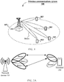
- FIG. 1 shows a wireless communications system used in this application.
- the wireless communications system may operate on a high frequency band, and is not limited to a long term evolution (Long Term Evolution, LTE) system, and may be a future evolved 5th generation (the 5th Generation, 5G) mobile communications system, a new radio (NR) system, a machine-to-machine (Machine to Machine, M2M) communications system, or the like.
- the wireless communications system 100 may include: one or more network devices 101, one or more terminals 103, and a core network (not shown).
- the network device 101 may be a base station.
- the base station may be configured to communicate with the one or more terminals, or may be configured to communicate with one or more base stations that have some terminal functions (for example, communication between a macro base station and a micro base station, such as an access point).
- the base station may be a base transceiver station (Base Transceiver Station, BTS) in a time division-synchronous code division multiple access (Time Division Synchronous Code Division Multiple Access, TD-SCDMA) system, or may be an evolved NodeB (Evolutional Node B, eNB) in the LTE system, or a gNB in the 5G system or the new radio (NR) system.
- BTS Base Transceiver Station
- TD-SCDMA time division-synchronous code division multiple access
- eNB evolved NodeB
- the base station may alternatively be an access point (Access Point, AP), a transmission point (Trans TRP), a central unit (Central Unit, CU), or another network entity, and
- the terminals 103 may be distributed in the entire wireless communications system 100, may be static, or may be mobile.
- the terminal 103 may be a mobile device, a mobile station (mobile station), a mobile unit (mobile unit), an M2M terminal, a radio unit, a remote unit, a terminal agent, a mobile client, or the like.
- the wireless communications system 100 is a multi-beam communications system.
- the network device 101 may be provided with a large-scale antenna array and control, by using a beamforming technology, the antenna array to generate beams pointing to different directions. To cover an entire cell 107, the network device 101 needs to use a plurality of beams pointing to different directions.
- the network device 101 may sequentially use the beams pointing to different directions to transmit a radio signal (for example, a downlink reference signal and/or a downlink synchronization signal block (synchronization signal block, SS block)).
- a radio signal for example, a downlink reference signal and/or a downlink synchronization signal block (synchronization signal block, SS block)
- This process is referred to as beam sweeping (Beam scanning).
- the terminal 103 measures a transmit beam and determines signal quality of the transmit beam that can be received by the terminals 103. This process is referred to as beam measurement (Beam measurement).
- the terminal 103 may also be provided with an antenna array, and may change different beams to receive and send a signal.
- the network device 101 and the terminal 103 each may use a plurality of beams to perform communication.
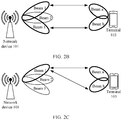
- a random access (Random Access, RA) process a manner in which the terminal 103 sends a random access preamble (preamble) to the network device 101 may be shown in FIG. 2A to FIG. 2C .
- FIG. 2A shows that the terminal 103 sends a preamble to the network device 101 by using a same transmit beam (such as a beam a), and the network device 101 receives the preamble by using a plurality of receive beams (such as beams 1 and 3).
- a same transmit beam such as a beam a
- the network device 101 receives the preamble by using a plurality of receive beams (such as beams 1 and 3).
- the beam a and the beam 1 are paired, and the beam a and the beam 3 are paired.
- FIG. 2B shows that the terminal 103 sends a preamble to the network device 101 by using a plurality of transmit beams (such as beams a and b), and the network device 101 receives the preamble by using a plurality of receive beams (such as beams 1 and 3).
- a plurality of transmit beams such as beams a and b
- a plurality of receive beams such as beams 1 and 3.
- FIG. 2C shows that the terminal 103 sends a preamble to the network device 101 by using a plurality of transmit beams (such as beams a and b), and the network device 101 receives the preamble by using a same receive beam (such as a beam 1).
- a transmit beam such as beams a and b
- a same receive beam such as a beam 1).
- the beam a and the beam 1 are paired
- the beam b and the beam 1 are paired.
- three preamble sending scenarios shown in FIG. 2A to FIG. 2C may simultaneously exist in random access procedures of different terminals 103, or may successively exist in a plurality of random access procedures of a same terminal 103. This is not limited herein.
- transmit and receive beams of the network device may be referred to as a base station beam, including a base station transmit beam and a base station receive beam.
- the base station transmit beam is a downlink signal mentioned in this application.
- transmit and receive beams of the terminal may be referred to as a terminal beam, including a terminal transmit beam and a terminal receive beam.
- each base station receive beam corresponds to one base station transmit beam.
- that the base station receive beam is in a one-to-one correspondence with the base station transmit beam means that the base station receive beam and the base station transmit beam have same directivity.
- the base station receive beam and the base station transmit beam corresponding to the base station receive beam may be a same beam and can share a same transceiver apparatus.
- an antenna port corresponding to the base station receive beam and an antenna port corresponding to the base station transmit beam corresponding to the base station receive beam may be in a quasi co-location (Quasi Co-location, QCL) relationship.
- the quasi co-location relationship means that at least one of the following parameters of one port is the same as the parameter of another port/or at least one of the following parameters of one port is in a determined correspondence with the parameter of another port: an angle of arrival AoA (angle of arrival), a dominant angle of arrival Dominant AoA, an average angle of arrival, a power angular spectrum of an angle of arrival (power angular spectrum (PAS) of AoA), an angle of departure AoD (angle of departure), a dominant angle of departure, an average angle of departure, a power angular spectrum of an angle of departure, terminal transmit beam beamforming, terminal receive beam beamforming, spatial channel correlation, base station transmit beam beamforming, base station receive beam beamforming, an average channel gain, an average channel delay, a delay spread delay spread,
- selecting a base station transmit beam with excellent terminal directivity is equivalent to selecting a base station receive beam with excellent terminal directivity.
- what is mainly discussed is how to switch to a base station transmit beam with higher terminal directivity on a terminal side.
- the network device receives, by using a corresponding base station receive beam, a preamble retransmitted by the terminal, thereby improving a success rate of preamble retransmission.
- same downlink signals/base station beams/terminal beams means that the same downlink signals/base station beams/terminal beams have a same space receiving parameter and/or a same antenna port.
- at least one of the following parameters of one downlink signal/base station beam/terminal beam is the same as the parameter of another downlink signal/base station beam/terminal beam/or at least one of the following parameters of one downlink signal/base station beam/terminal beam is in a determined correspondence with the parameter of another downlink signal/base station beam/terminal beam: an angle of arrival AoA (angle of arrival), a dominant angle of arrival Dominant AoA, an average angle of arrival, a power angular spectrum of an angle of arrival (power angular spectrum (PAS) of AoA), an angle of departure AoD (angle of departure), a dominant angle of departure, an average angle of departure, a power angular spectrum of an angle of departure, terminal transmit beam beamforming, terminal receive beam beamforming, spatial channel correlation, base station transmit beam beam beam
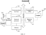
- FIG. 3 shows a terminal 200 according to some embodiments of this application.
- the terminal 200 may include: one or more terminal processors 201, a memory 202, a communications interface 203, a receiver 205, a transmitter 206, a coupler 207, an antenna 208, a terminal interface 202, and an input/output module (including an audio input/output module 210, a key input module 211, a display 212, and the like).
- These components may be connected by using a bus 204 or in another manner. In FIG. 3 , for example, the components are connected by using the bus.
- the communications interface 203 may be configured for communication between the terminal 200 and another communications device, for example, a network device.
- the network device may be a network device 300 shown in FIG. 3 .
- the communications interface 203 may be a long term evolution (LTE) (4G) communications interface, or may be a 5G or future new radio communications interface.
- LTE long term evolution
- the terminal 200 may be configured with a wired communications interface 203, for example, a local access network (Local Access Network, LAN) interface.
- LAN local access network
- the transmitter 206 may be configured to transmit a signal output by the terminal processor 201, for example, implement directional sending through beamforming.
- the receiver 205 may be configured to receive a mobile communication signal received by the antenna 208, for example, implement directional receiving through beamforming.
- a transmitter 305/receiver 306 may include a beamforming controller, configured to multiply a transmitted signal/received signal and a weight vector Wi, ..., or W m , to control directional transmission/reception of the signal.
- the beamforming controller in the transmitter 305/receiver 306 changes a value obtained by multiplying the transmitted signal/received signal and a weight vector, so that base station beam switching mentioned in this application can be implemented.
- the transmitter 206 and the receiver 205 may be considered as a wireless modem. There may be one or more transmitters 206 and receivers 205 in the terminal 200.
- the antenna 208 may be configured to convert electromagnetic energy in a transmission line into an electromagnetic wave in free space, or convert an electromagnetic wave in free space into electromagnetic energy in a transmission line.
- the coupler 207 is configured to divide a mobile communications signal received by the antenna 208 into a plurality of mobile communications signals and allocate the plurality of mobile communications signals to a plurality of receivers 205.
- the terminal 200 may include another communications component, for example, a GPS module, a bluetooth (Bluetooth) module, or a wireless fidelity (Wireless Fidelity, Wi-Fi) module.
- the terminal 200 may support another wireless communications signal, for example, a satellite signal or a short wave signal.
- the terminal 200 may be provided with a wired network interface (for example, a LAN interface) to support wired communication.
- the input/output module may be configured to implement interaction between the terminal 200 and a terminal/an external environment, and may mainly include the audio input/output module 210, the key input module 211, the display 212, and the like. Specifically, the input/output module may also include a camera, a touchscreen, a sensor, and the like. The input/output module communicates with the terminal processor 201 by using the terminal interface 209.
- the memory 202 is coupled to the terminal processor 201, and is configured to store various software programs and/or a plurality of sets of instructions.
- the memory 202 may include a high-speed random access memory, and may include a non-volatile memory, for example, one or more disk storage devices, flash memory devices, or other non-volatile solid-state storage devices.
- the memory 202 may store an operating system (briefly referred to as a system in the following), for example, an embedded operating system such as ANDROID, IOS, WINDOWS, or LINUX.
- the memory 202 may further store a network communication program.
- the network communication program may be used for communication with one or more additional devices, one or more terminal devices, and one or more network devices.
- the memory 202 may further store a terminal interface program.
- the terminal interface program may vividly display content of an application program by using a graphical operation interface, and receive, by using an input control such as a menu, a dialog box, or a key, a control operation performed by a terminal on an application.
- the memory 202 may be configured to store a program for implementing, on a terminal 200 side, the signal transmission method provided in one or more embodiments of this application.
- the signal transmission method provided in one or more embodiments of this application refer to subsequent embodiments.
- the terminal processor 201 may be configured to read and execute a computer readable instruction. Specifically, the terminal processor 201 may be configured to invoke a program stored in the memory 212, for example, the program for implementing, on the terminal 200 side, the signal transmission method provided in one or more embodiments of this application, and execute an instruction included in the program.
- the terminal 200 may be the terminal 103 in the wireless communications system 100 shown in FIG. 1 , and may be implemented as a mobile device, a mobile station (mobile station), a mobile unit (mobile unit), a radio unit, a remote unit, a terminal agent, a mobile client, or the like.
- the terminal 200 shown in FIG. 3 is merely an implementation of the embodiments of this application. In actual application, the terminal 200 may also include more or fewer components, and this is not limited herein.
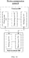
- FIG. 4 shows a network device 300 according to some embodiments of this application.
- the network device 300 may include: one or more network device processors 301, a memory 302, a communications interface 303, a transmitter 305, a receiver 306, a coupler 307, and an antenna 308. These components may be connected by using a bus 304 or in another manner. In FIG. 4 , for example, the components are connected by using the bus.
- the communications interface 303 may be configured for communication between the network device 300 and another communications device, for example, a terminal device or another network device.
- the terminal device may be the terminal 200 shown in FIG. 3 .
- the communications interface 303 and the communications interface 203 may be a long term evolution (LTE) (4G) communications interface, or may be a 5G or future new radio communications interface.
- LTE long term evolution
- the network device 300 may be configured with a wired communications interface 303 to support wired communication.
- a backhaul connection between a network device 300 and another network device 300 may be a wired communication connection.
- the transmitter 305 may be configured to transmit a signal output by the network device processor 301, for example, implement directional sending through beamforming.
- the receiver 306 may be configured to receive a mobile communication signal received by the antenna 308, for example, implement directional receiving through beamforming.
- a transmitter 305/receiver 306 may include a beamforming controller, configured to multiply a transmitted signal/received signal and a weight vector W'i, ..., or W' m , to control directional transmission/reception of the signal.
- the beamforming controller in the transmitter 305/receiver 306 changes a value obtained by multiplying the transmitted signal/received signal and a weight vector, so that base station beam switching mentioned in this application can be implemented.
- the transmitter 305 and the receiver 306 may be considered as a wireless modem. There may be one or more transmitters 305 and receivers 306 in the network device 300.
- the antenna 308 may be configured to convert electromagnetic energy in a transmission line into an electromagnetic wave in free space, or convert an electromagnetic wave in free space into electromagnetic energy in a transmission line.
- the coupler 307 may be configured to divide mobile communications signals into a plurality of signals and allocate the mobile communications signals to a plurality of receivers 306.
- the memory 302 is coupled to the network device processor 301, and is configured to store various software programs and/or a plurality of sets of instructions.
- the memory 302 may include a high-speed random access memory, and may include a non-volatile memory, for example, one or more disk storage devices, flash memory devices, or other non-volatile solid-state storage devices.
- the memory 302 may store an operating system (briefly referred to as a system in the following), for example, an embedded operating system such as uCOS, VxWorks, or RTLinux.
- the memory 302 may further store a network communication program.
- the network communication program may be used for communication with one or more additional devices, one or more terminal devices, and one or more network devices.
- the network device processor 301 may be configured to manage a radio channel, establish and disconnect a call and communication link, provide cell handover control for a terminal in a local control area, and the like.
- the network device processor 301 may include an administration module/communication module (Administration Module/Communication Module, AM/CM) (a center for speech path switching and information exchanging), a basic module (Basic Module, BM) (configured to complete call processing, signaling processing, radio resource management, radio link management, and circuit maintenance functions), a transcoder and submultiplexer (Transcoder and SubMultiplexer, TCSM) (configured to complete multiplexing/demultiplexing and transcoding functions), and the like.
- AM/CM Administration Module/Communication Module
- Base Module Basic Module
- TCSM transcoder and submultiplexer
- the network device processor 301 may be configured to read and execute a computer readable instruction. Specifically, the network device processor 301 may be configured to invoke a program stored in the memory 302, for example, a program for implementing, on a network device 300 side, the signal transmission method provided in one or more embodiments of this application, and execute an instruction included in the program.
- the network device 300 may be the network device 101 in the wireless communications system 100 shown in FIG. 1 , and may be implemented as a base transceiver station, a wireless transceiver, a basic service set (BSS), an extended service set (ESS), a NodeB, an eNodeB, an access point, a TRP, or the like.
- BSS basic service set
- ESS extended service set
- NodeB NodeB
- eNodeB an access point
- TRP Transmission Control Protocol
- the network device 300 shown in FIG. 4 is merely an implementation of the embodiments of this application. In actual application, the network device 300 may also include more or fewer components, and this is not limited herein.
- an embodiment of this application provides a signal transmission method.
- a downlink signal sent by using each downlink beam is separately associated with a random access resource.
- a network device receives, by using a base station receive beam corresponding to each downlink beam, a preamble on a random access resource associated with each downlink signal.
- a terminal may select a downlink signal with excellent signal quality from a plurality of downlink signals based on signal quality that is of the downlink signals and that is obtained through measurement, and switch to a random access resource associated with the downlink signal to perform preamble retransmission.
- the network device receives the preamble by using the base station receive beam corresponding to the downlink beam, so as to improve a success rate of preamble retransmission, thereby reducing latency. That is, during preamble retransmission, the terminal may switch to a random access resource associated with a downlink signal with excellent signal quality to perform preamble retransmission.
- a random access resource may include a time-frequency resource of a preamble and/or a preamble.
- random access resource switching means that when random access preamble retransmission is performed, a random access resource used in this preamble retransmission is different from a random access resource used in previous preamble transmission.
- different random access resources are associated with different downlink signals, and a downlink signal uniquely corresponds to a downlink beam. Therefore, switching a random access resource is equivalent to switching a downlink beam, and is also equivalent to switching a base station receive beam that is used to receive a preamble.
- a downlink signal may include at least one of the following: a synchronization signal block (synchronization signal block, SS block) and a channel state information-reference signal (Channel State Information Reference Signal, CSI-RS).
- the SS block corresponds to N OFDM symbols.
- One SS block includes at least one of the following: a primary synchronization signal (primary synchronization signal, PSS), a secondary synchronization signal (secondary synchronization signal, SSS), a physical broadcast signal (physical broadcast channel, PBCH), or a demodulation reference signal (demodulation reference signal, DMRS) (for example, a PBCH DMRS).
- FIG. 5A to FIG. 5C are used as an example below for description.
- a current downlink signal received by a terminal is a downlink signal 2
- a preamble resource separately associated with a downlink signal sent by using each downlink beam is shown in FIG. 5A .
- a network device sequentially sends downlink signals (such as an SS block) by using a plurality of downlink beams.
- a downlink beam uniquely corresponds to a downlink signal.
- a downlink beam 1 is used to send an SS block 1
- a downlink beam 2 is used to send an SS block 2.
- the terminal may measure signal quality of a downlink signal (such as an SS block), and determine, based on the measured signal quality, to switch to a random access resource associated with a downlink signal 3 to perform preamble retransmission.
- signal quality of the downlink signal 3 is higher than that of the downlink signal 2.
- a downlink beam used to send the downlink signal 3 has higher terminal directivity than the downlink beam used to send the downlink signal 2.
- the terminal retransmits a preamble on the random access resource (namely, a random access resource 3) associated with the downlink signal 3.
- the network device sequentially receives, by using base station receive beams separately corresponding to downlink beams, preambles on preamble resources separately associated with downlink signals. It may be understood that the network device can successfully receive the preamble on the random access resource 3 by using a base station receive beam corresponding to a downlink beam 3.
- the terminal may send a preamble to the network device by using a same beam (for example, a beam a), or may send a preamble to the network device by using a plurality of beams (for example, beams a, b, and c). This is not limited herein.
- the network device receives the preamble by using the base station receive beam corresponding to the downlink beam 3, thereby improving a success rate of preamble retransmission.
- a random access resource associated with each downlink signal may be agreed in advance.
- a base station receive beam corresponding to each downlink beam is used to receive a preamble only on a preamble resource associated with a downlink signal sent by using the downlink beam.
- only the base station receive beam corresponding to the downlink beam 3 that is used to send the downlink signal 3 is used to receive the preamble on the random access resource 3.
- FIG. 5A to FIG. 5C are merely used to explain this application and shall not be construed as a limitation.
- a random access resource separately associated with each downlink signal shown in FIG. 5A may be configured by the network device by using any one or more of system information (system information, SI), remaining system information (remaining system information, RMSI), a downlink physical control channel (physical downlink control channel, PDCCH), downlink control information (downlink control information, DCI), a MAC-CE (medium access control - control element), RRC (radio resource control, RRC) signaling, or the like.
- system information system information
- RMSI remaining system information
- RMSI remaining system information
- PDCCH physical downlink control channel
- DCI downlink control information
- MAC-CE medium access control - control element
- RRC radio resource control
- the random access resource switching condition may be used to determine whether to switch a random access resource used for preamble retransmission.
- the terminal Before performing random access resource switching, the terminal may measure quality of each downlink signal, analyze a signal quality change of a current downlink signal and/or a candidate downlink signal, and finally determine, based on the signal quality change and the random access resource switching condition, whether to switch a random access resource.
- the signal quality change of the downlink signal may include but is not limited to the following:
- a configuration parameter used to determine the signal quality change may include at least one of the following: a third threshold, a fourth threshold, amplitude hysteresis (hysteresis), an offset value Obn associated with the candidate downlink signal, a frequency offset value Ofn associated with the candidate downlink signal, a quantity N of downlink signals, or time to trigger (TimeToTrigger).
- the switching condition provided in this application may include but is not limited to the following:
- Ms represents signal quality of a current downlink signal
- Mn represents signal quality of a candidate downlink signal
- Hysteresis represents amplitude hysteresis
- Obn represents an offset value associated with the candidate downlink signal
- Ofn represents a frequency offset value associated with the candidate downlink signal
- Threshold 3 represents a third threshold
- Threshold4 represents a fourth threshold.
- the fifth switching condition is applicable to: Signal quality of a current downlink signal is reduced, and the signal quality of the candidate downlink signal is improved.
- each switching condition may be determined based on an actual requirement. This is not limited in this application.
- a specific decision of the terminal to perform random access resource switching based on each switching condition may also be determined based on an actual requirement. This is not limited in this application.
- a plurality of embodiments are used to describe each switching condition and specific implementation of performing random access resource switching based on the switching condition. However, this is not limited to descriptions in subsequent embodiments, and the terminal may further determine the specific decision of the random access resource switching based on an actual requirement.
- This application provides a plurality of switching conditions. Specifically, which one (s) is (are) used may be decided by the terminal based on an actual requirement. This is not limited herein. How to perform resource switching based on a switching condition is described in detail in the subsequent embodiments. Details are not described herein again.
- the configuration parameter used to determine the foregoing various signal quality changes may be collectively referred to as a first configuration parameter.
- one or more of the first configuration parameters may be configured by the network device by using any one or more of system information (SI), remaining system information (RMSI), a downlink physical control channel (PDCCH), downlink control information (DCI), a MAC-CE, RRC signaling, and the like.
- SI system information
- RMSI remaining system information
- PDCH downlink physical control channel
- DCI downlink control information
- MAC-CE radio resource control information
- RRC signaling and the like.
- one or more of the first configuration parameters may be defined by using a protocol, or may be pre-stored or pre-configured by the terminal.
- the amplitude hysteresis (hysteresis), the time to trigger (TimeToTrigger), the offset value Obs associated with the current downlink signal, the frequency offset value Ofs associated with the current downlink signal, the offset value Obn associated with the candidate downlink signal, and the frequency offset value Ofn associated with the candidate downlink signal may be 0 by default.
- preamble transmit power may be further increased.
- an increase in the preamble transmit power may cause interference to another terminal.
- a principle of increasing preamble transmit power during beam switching needs to be specified.
- the beam switching not only can include the random access resource switching (that is, equivalent to base station beam switching) described in the foregoing content, but also can include terminal beam switching or beam pair (base station beam-terminal beam) switching.
- a plurality of times of beam switching may be performed at each power ramping level (powerRampingLevel).
- power ramping is performed only once every M times of beam switching. This is equivalent to that power ramping is performed only once after beam sweeping.
- M is a positive integer and is not greater than a maximum quantity of beam switching times, for example, a maximum quantity of random access resource switching times (that is, equivalent to a quantity of base station beam switching times), a maximum quantity of terminal beam switching times, or a maximum quantity of beam pair switching times.
- preamble transmit power control policies in different beam switching scenarios are described subsequently by using a plurality of embodiments, and details are not described herein.
- signal quality may be embodied in the following manners:
- the signal quality may also be determined based on at least one of the following parameters: a path loss (Path Loss, PL), base station downlink reference signal transmit power, a gain of a base station transmitted signal (for example, a transmit beam beamforming gain), a gain of a base station received signal (for example, a receive beam beamforming gain), preamble initial received power, a difference between a gain of a base station transmitted signal and a gain of a base station received signal, a gain of a terminal downlink signal received signal (for example, a receive beam beamforming gain), a gain of a terminal uplink random access preamble transmitted signal (for example, a transmit beam beamforming gain), terminal random access preamble transmit power, and a difference between a gain of a terminal downlink signal receive beam and a gain of a terminal uplink random access preamble transmitted signal.
- a path loss Path Loss, PL
- PL path loss
- base station downlink reference signal transmit power for example, a gain of a base
- the spatial path loss PL is determined based on at least one of the base station downlink reference signal transmit power, the gain of the base station transmitted signal, the gain of the base station received signal, the difference between the gain of the base station transmitted signal and the gain of the base station received signal, the gain of the terminal downlink signal received signal, the gain of the terminal uplink random access preamble transmitted signal, the difference between the gain of the terminal downlink signal receive beam and the gain of the terminal uplink random access preamble transmitted signal, and RSRP.
- the signal quality is the RSRP
- RSRP, RSRQ, and an RS-SINR in LTE are all cell-level parameters for measuring signal quality. While RSRP, RSRQ, and an RS-SINR in this application are beam-level parameters for measuring signal quality.
- the signal quality may be obtained by the terminal through measurement based on a synchronization signal block, for example, obtained through measurement based on an SSS and/or a PBCH DMRS.
- the signal quality may be obtained by the terminal through measurement based on a downlink reference signal, such as a channel state information-downlink reference signal (CSI-RS).
- CSI-RS channel state information-downlink reference signal
- a terminal performs random access resource switching based on a first switching condition.
- the first switching condition may be expressed as: Ms ⁇ Hysteresis > Threshold 1
- Ms represents signal quality of a current downlink signal
- Hysteresis represents amplitude hysteresis
- Threshold1 represents a first threshold.
- TimeToTrigger in the figure represents time to trigger.
- the first switching condition As shown in FIG. 6 , if the first switching condition is met, it indicates that the signal quality of the current downlink signal is improved.
- the terminal may perform but is not limited to performing the following operations.
- the terminal may continue to select a random access resource associated with the current downlink signal to perform random access, and send a random access preamble again or for a plurality of times.
- the terminal stops measuring another downlink signal immediately or after the time to trigger (TimeToTrigger).
- the terminal measures, immediately or after the time to trigger (TimeToTrigger), the signal quality of the current downlink signal by using a longer time period.
- the terminal may further perform another operation based on an actual requirement.
- the first switching condition is not limited to the inequality (A1-1), and may also be properly modified based on an actual requirement. This is not limited herein.
- a reverse condition of the first switching condition may be expressed as: Ms + Hysteresis ⁇ Threshold 1
- the reverse condition of the first switching condition if the reverse condition of the first switching condition is met, the previous related operation performed after the first switching condition is met, for example, the foregoing several optional operations, may be stopped. This is not limited thereto, and the terminal may further perform another operation based on an actual requirement. This is not limited herein.
- the reverse condition of the first switching condition is not limited to the inequality (A1-2), and may also be properly modified based on an actual requirement. This is not limited herein.
- a terminal performs random access resource switching based on a second switching condition.
- the second switching condition may be expressed as: Ms + Hysteresis ⁇ Threshold 1
- Ms represents signal quality of a current downlink signal
- Hysteresis represents amplitude hysteresis
- Threshold1 represents a first threshold.
- TimeToTrigger in the figure represents time to trigger.
- the second switching condition As shown in FIG. 7 , if the second switching condition is met, it indicates that the signal quality of the current downlink signal is reduced.
- the terminal may perform but is not limited to performing the following operations.
- the terminal may continue to select a random access resource associated with the current downlink signal to perform random access, and send a random access preamble again or for a plurality of times.
- the terminal before this step, if the terminal measures only the current downlink signal, the terminal starts to measure another downlink signal or a plurality of other downlink signals immediately or after the time to trigger (TimeToTrigger).
- the terminal before this step, if the terminal measures a plurality of downlink signals, the terminal continues to measure signal quality of another downlink signal or a plurality of other downlink signals.
- a quantity of downlink signals measured by the terminal does not exceed a total quantity N of downlink signals.
- the terminal measures, immediately or after the time to trigger (TimeToTrigger), the signal quality of the current downlink signal or signal quality of another downlink signal by using a shorter time period.
- the terminal may further perform another operation based on an actual requirement.
- the second switching condition is not limited to the inequality (A2-1), and may also be properly modified based on an actual requirement. This is not limited herein.
- a reverse condition of the second switching condition may be expressed as: Ms ⁇ Hysteresis > Threshold 1
- the reverse condition of the second switching condition if the reverse condition of the second switching condition is met, the previous related operation performed after the second switching condition is met, for example, the foregoing several optional operations, may be stopped.
- the terminal may further perform another operation based on an actual requirement.
- the reverse condition of the second switching condition is not limited to the inequality (A2-2), and may also be properly modified based on an actual requirement. This is not limited herein.
- a terminal performs random access resource switching based on a third switching condition.
- the third switching condition may be expressed as: Mn + Obn + Ofn ⁇ Hysteresis > Ms + Obs + Ofs + Offset 1
- Ms represents signal quality of a current downlink signal
- Mn represents signal quality of a candidate downlink signal
- Hysteresis represents amplitude hysteresis
- Obn represents an offset value associated with the candidate downlink signal
- Ofn represents a frequency offset value associated with the candidate downlink signal
- Obs represents an offset value associated with the current downlink signal
- Ofs represents a frequency offset value associated with the current downlink signal
- Offset1 represents a first offset.
- TimeToTrigger in the figure represents time to trigger.
- the third switching condition indicates that the signal quality of the candidate downlink signal becomes higher than the signal quality of the current downlink signal, and is at least higher than the first offset Offset1.
- the terminal may perform but is not limited to performing the following operations.
- the terminal may switch to a random access resource associated with the candidate downlink signal to perform random access, and send a random access preamble again.
- the terminal may select to switch to a random access resource associated with a candidate downlink signal on a current frequency band or another frequency band.
- the terminal switches to the random access resource associated with the candidate downlink signal.
- K is a positive integer.
- the terminal switches to the random access resource associated with the candidate downlink signal.
- the terminal continues to use the random access resource associated with the current downlink signal to perform random access.
- T is a positive number.
- the foregoing two optional operations are mainly applicable to a scenario in which the terminal may perform, after a quantity of times of retransmission on a random access resource associated with a downlink signal exceeds a specific quantity of times, random access by using a random access resource associated with another downlink signal.
- the terminal may perform, after a quantity of times of retransmission on a random access resource associated with a downlink signal exceeds a specific quantity of times, random access by using a random access resource associated with another downlink signal.
- a relatively large quantity of terminals in random access resources associated with some downlink signals there are a relatively large quantity of terminals in random access resources associated with some downlink signals, and this results in a relatively high contention probability or a relatively large transmission backoff value.
- random access resource switching may be considered.
- the terminal may stop measuring the current downlink signal immediately or after the time to trigger (TimeToTrigger), and select the random access resource associated with the candidate downlink signal to perform random access.
- TimeToTrigger time to trigger
- the terminal may measure, by using a longer time period, the signal quality of the current downlink signal before random access resource switching.
- the terminal device may stop measuring the signal quality of the current downlink signal before the random access resource switching.
- the terminal may further perform another operation based on an actual requirement.
- an entry condition of the third switching condition is not limited to the inequality (A3-1), and may also be properly modified based on an actual requirement. This is not limited herein.
- a reverse condition of the third switching condition may be expressed as: Mn + Obn + Ofn + Hysteresis ⁇ Ms + Obs + Ofs + Offset 1
- the terminal may perform but is not limited to performing the following operations.
- the terminal may continue to select the random access resource associated with the current downlink signal to perform random access, and send a random access preamble again or for a plurality of times.
- the terminal may measure, immediately or after the time to trigger (TimeToTrigger), the signal quality of the current downlink signal or the candidate downlink signal by using a shorter time period.
- TimeToTrigger the time to trigger
- the terminal may further perform another operation based on an actual requirement.
- the reverse condition of the third switching condition is not limited to the inequality (A3-2), and may also be properly modified based on an actual requirement. This is not limited herein.
- a total quantity of times of random access resource switching performed by the terminal in a random access procedure does not exceed a total quantity N of downlink signals.
- a terminal performs random access resource switching based on a fourth switching condition.
- the fourth switching condition may be expressed as: Mn + Obn + Ofn ⁇ Hysteresis > Threshold 2
- Mn represents signal quality of a candidate downlink signal
- Hysteresis represents amplitude hysteresis
- Obn represents an offset value associated with the candidate downlink signal
- Ofn represents a frequency offset value associated with the candidate downlink signal
- Threshold2 represents a second threshold.
- TimeToTrigger in the figure represents time to trigger.
- the fourth switching condition is met, it indicates that the signal quality of the candidate downlink signal is improved.
- the terminal may perform but is not limited to performing the following operations.
- the terminal may switch to a random access resource associated with the candidate downlink signal to perform random access, and send a random access preamble again.
- the terminal may select to switch to a random access resource associated with a candidate downlink signal on a current frequency band or another frequency band.
- the terminal may stop measuring a current downlink signal immediately or after time to trigger (TimeToTrigger), and select the random access resource associated with the candidate downlink signal to perform random access.
- TimeToTrigger time to trigger
- the terminal may measure, by using a longer time period, signal quality of the current downlink signal before random access resource switching.
- the terminal may stop measuring the signal quality of the current downlink signal before the random access resource switching.
- Load (load) of a random access resource associated with each downlink signal or a quantity of terminals is further considered.
- the terminal may perform but is not limited to performing the following operations.
- the terminal switches to the random access resource associated with the candidate downlink signal.
- K is a positive integer.
- the terminal switches to the random access resource associated with the candidate downlink signal.
- the terminal continues to use the random access resource associated with the current downlink signal to perform random access.
- T is a positive number.
- the foregoing two optional operations are mainly applicable to a scenario in which the terminal may perform, after a quantity of times of retransmission on a random access resource associated with a downlink signal exceeds a specific quantity of times, random access by using a random access resource associated with another downlink signal.
- the terminal may perform, after a quantity of times of retransmission on a random access resource associated with a downlink signal exceeds a specific quantity of times, random access by using a random access resource associated with another downlink signal.
- a relatively large quantity of terminals in random access resources associated with some downlink signals there are a relatively large quantity of terminals in random access resources associated with some downlink signals, and this results in a relatively high contention probability or a relatively large transmission backoff value.
- random access resource switching may be considered.
- the terminal may further perform another operation based on an actual requirement.
- the fourth switching condition is not limited to the inequality (A4-1), and may also be properly modified based on an actual requirement. This is not limited herein.
- a reverse condition of the fourth switching condition may be expressed as: Mn + Obn + Ofn + Hysteresis ⁇ Threshold 2
- the terminal may perform but is not limited to performing the following operations.
- the terminal may continue to select the random access resource associated with the current downlink signal to perform random access, and send a random access preamble again or for a plurality of times.
- the terminal may measure, immediately or after the time to trigger (TimeToTrigger), the signal quality of the current downlink signal or the signal quality of the candidate downlink signal by using a shorter time period.
- TimeToTrigger the time to trigger
- the terminal may further perform another operation based on an actual requirement.
- the reverse condition of the fourth switching condition is not limited to the inequality (A4-2), and may also be properly modified based on an actual requirement. This is not limited herein.
- a total quantity of times of random access resource switching performed by the terminal in a random access procedure does not exceed a total quantity N of downlink signals.
- a terminal performs random access resource switching based on a fifth switching condition.
- the fifth switching condition may be expressed as: Ms + Hysteresis ⁇ Threshold 3 and Mn + Obn + Ofn ⁇ Hysteresis > Threshold 4
- Ms represents signal quality of a current downlink signal
- Mn represents signal quality of a candidate downlink signal
- Hysteresis represents amplitude hysteresis
- Obn represents an offset value associated with the candidate downlink signal
- Ofn represents a frequency offset value associated with the candidate downlink signal
- Threshold 3 represents a third threshold
- Threshold4 represents a fourth threshold.
- TimeToTrigger in the figure represents time to trigger.
- the fifth switching condition is met, in other words, both the inequality (A5-1) and the inequality (A5-2) are met, it indicates that the signal quality of the current downlink signal is reduced (lower than the third threshold), and the signal quality of the candidate downlink signal is improved (lower than the fourth threshold).
- the terminal may perform but is not limited to performing the following operations.
- the terminal may switch to a random access resource associated with the candidate downlink signal to perform random access, and send a random access preamble again.
- the terminal may select to switch to a random access resource associated with a candidate downlink signal on a current frequency band or another frequency band.
- the terminal may stop measuring the current downlink signal immediately or after time to trigger (TimeToTrigger), and select the random access resource associated with the candidate downlink signal to perform random access.
- TimeToTrigger time to trigger
- the terminal may measure, by using a longer time period, the signal quality of the current downlink signal before random access resource switching.
- the terminal may stop measuring the signal quality of the current downlink signal before the random access resource switching.
- the terminal may switch to the random access resource associated with the candidate downlink signal to perform random access.
- Load (load) of a random access resource associated with each downlink signal or a quantity of terminals is further considered.
- the terminal may perform but is not limited to performing the following operations.
- the terminal switches to the random access resource associated with the candidate downlink signal.
- K is a positive integer.
- the terminal switches to the random access resource associated with the candidate downlink signal.
- the terminal continues to use the random access resource associated with the current downlink signal to perform random access.
- T is a positive number.
- the foregoing two optional operations are mainly applicable to a scenario in which the terminal may perform, after a quantity of times of retransmission on a random access resource associated with a downlink signal exceeds a specific quantity of times, random access by using a random access resource associated with another downlink signal.
- the terminal may perform, after a quantity of times of retransmission on a random access resource associated with a downlink signal exceeds a specific quantity of times, random access by using a random access resource associated with another downlink signal.
- a relatively large quantity of terminals in some downlink signals and this results in a relatively high contention probability or a relatively large transmission backoff value.
- random access resource switching may be considered.
- the terminal may further perform another operation based on an actual requirement.
- the fifth switching condition is not limited to the inequalities (A5-1) and (A5-2), and may also be properly modified based on an actual requirement. This is not limited herein.
- a reverse condition of the fifth switching condition may be expressed as: Ms ⁇ Hysteresis 3 > Threshold 3 and Mn + Obn + Ofn + Hysteresis 4 ⁇ Threshold 4
- the terminal may perform but is not limited to performing the following operations.
- the terminal may continue to select a random access resource associated with the current downlink signal to perform random access, and send a random access preamble again or for a plurality of times.
- the terminal may measure, immediately or after the time to trigger (TimeToTrigger), the signal quality of the current downlink signal or the candidate downlink signal by using a shorter time period.
- TimeToTrigger the time to trigger
- the terminal may further perform another operation based on an actual requirement.
- the reverse condition of the fifth switching condition is not limited to the inequalities (A6-1) and (A6-2), and may also be properly modified based on an actual requirement. This is not limited herein.
- a total quantity of times of random access resource switching performed by the terminal in a random access procedure does not exceed a total quantity N of downlink signals.
- This embodiment is applicable to a scenario in which a plurality of downlink signals are separately sent by a network device on a plurality of different frequency bands by using a same downlink beam.
- the current downlink signal and the candidate downlink signal respectively correspond to a current frequency band and a candidate frequency band.
- Downlink signals on different frequency bands are separately associated with different random access resources.
- a relatively large quantity of terminals on a frequency band may result in a relatively high contention probability or a relatively large transmission backoff value, or deep fading on a frequency band.
- random access resource switching may be considered.
- the terminal may refer to any random access resource switching solution in the Embodiment 1 to the Embodiment 5, and performs, in a similar manner, random access resource switching based on measured signal quality of a downlink signal received on the current frequency band and measured signal quality of a downlink signal received on the candidate frequency band.
- signal quality may be replaced with signal quality of a downlink signal sent on each frequency band
- an offset value associated with a downlink signal may be replaced with a signal offset value associated with a downlink signal sent on each frequency band
- a frequency offset value associated with a downlink signal may be replaced with a frequency offset value associated with a downlink signal sent on each frequency band.
- the terminal measures a plurality of downlink signals. If signal quality of a downlink signal with highest signal quality does not exceed a pre-stored or pre-configured threshold or a threshold specified by a base station, the terminal is not allowed to perform downlink random access resource switching. In another embodiment, the terminal measures a plurality of downlink signals. If signal quality of a downlink signal with highest signal quality does not exceed a pre-stored or pre-configured threshold or a threshold specified by a base station, a quantity of times of downlink random access resource switching allowed to be performed by the terminal does not exceed a pre-stored or pre-configured quantity of threshold times or a quantity of threshold times specified by the base station.
- a terminal does not perform random access resource switching when any one or more of the following conditions are met.
- configuration information of a base station indicates: On a premise that the terminal is allowed to switch a random access resource in a retransmission process or that the terminal determines whether to switch a random access resource in the retransmission process, the terminal determines/may determine/or should determine to switch a random access resource when any quantity of the following conditions are met.
- the terminal may switch from the random access resource associated with the current downlink signal to the random access resource associated with the candidate downlink signal.
- condition for not allowing random access resource switching and the condition for allowing random access resource switching in this embodiment may be combined with any of at least one switching condition of the Embodiment 1 to the Embodiment 6 in any manner.
- condition 1 for allowing random access resource switching may be combined with any of at least one switching condition of the Embodiment 2, the Embodiment 3, the Embodiment 4, the Embodiment 5, and the Embodiment 6.
- the example is merely a combination manner, and is not limited in actual application.
- the network device may configure a parameter related to each downlink signal (which may be referred to as a second configuration parameter).
- the parameter may include at least one of the following parameters: a maximum quantity of random access preamble transmission times, a maximum quantity of terminal beam switching times, a maximum quantity of base station beam switching times, a maximum quantity of beam pair switching times, a threshold parameter of a quantity of transmission times, downlink reference signal transmit power, a power ramping step, preamble initial received target power, a preamble format, a maximum power ramping level, and maximum transmit power P_CMAX.
- the second configuration parameter may be used to determine preamble transmit power.
- each of the foregoing three parameters 2 to 4 may be a single value, or may be a set or a value range.
- the maximum quantity of terminal beam switching times is ⁇ 1, 2, 3, 4, 6, 8 ⁇ .
- the maximum quantity of base station switching times is ⁇ 1, 2, 3, 4 ⁇ .
- the maximum quantity of beam pair switching times is ⁇ 1, 2, 3, 4, 6, 8, 10, 12 ⁇ .
- the terminal selects a value at each power ramping level to perform beam switching, and values selected at different levels may be different.
- the terminal selects a value at each power ramping level to perform beam switching, and values selected at all levels should be the same.
- terminal transmit beams and/or base station receive beams selected by the terminal at each power ramping level are the same.
- a gain of a base station transmitted signal is considered for the downlink reference signal transmit power (reference SignalPower), and a gain of a base station received signal is considered for the preamble initial received target power (preambleInitialReceivedTargetPower).
- a difference between a gain of a base station transmit beam and a gain of a base station received signal is considered for the downlink reference signal transmit power (referenceSignalPower).
- a difference between a gain of a base station transmit beam and a gain of a base station received signal is considered for the preamble initial received target power (preambleInitialReceivedTargetPower).
- reference signal transmit power (referenceSignalPower) of all downlink signals is different.
- preambleInitialReceivedTargetPower preambleInitialReceivedTargetPower
- a difference between a gain of a terminal synchronization signal receive beam and a gain of a random access preamble transmitted signal is considered for signal quality.
- a terminal fixedly uses one beam pair (a base station receive beam-a terminal transmit beam).
- the factor preambleInitialReceivedTargetPower + DELTA_PREAMBLE represents received power of a random access preamble that arrives at a network device when the random access preamble is initially transmitted.
- PREAMBLE_TRANSMISSION_COUNTER - 1) * powerRampingStep represents power ramping (ramping) power in a random access preamble retransmission process, and is used to ramp preamble transmit power, so as to improve a success probability of random access preamble transmission.
- a random access resource associated with a downlink signal is fixedly used, and preamble retransmission is performed by using K (one or more Ks configured by a network device) terminal beams at each power ramping level.
- K is a positive integer, and K is not greater than a maximum quantity of terminal beam switching times.
- a terminal may determine a terminal beam switching manner. This is not limited.
- the factor preambleInitialReceivedTargetPower + DELTA_PREAMBLE represents received power of a random access preamble that arrives at a network device when the random access preamble is initially transmitted.
- the factor powerRampingLevel * powerRampingStep (namely, floor((PREAMBLE_TRANSMISSION_COUNTER - 1) / K) * powerRampingStep or ceil(PREAMBLE_TRANSMISSION_COUNTER / N) * powerRampingStep) represents power ramping (ramping) power in a random access preamble retransmission process.
- the factor powerRampingLevel * powerRampingStep is used, so that the following can be controlled: preamble transmit power ramping is performed once every K times of terminal beam switching.
- K times of terminal beam switching should be performed at each power ramping level.
- K terminal beams separately used may be completely the same, where i and j are non-negative integers. In this way, excessively fast ramping of the preamble transmit power can be avoided, and interference may be reduced as much as possible while a success rate of preamble retransmission is improved.
- a terminal transmit beam is fixedly used.
- preamble retransmission is performed by using (one or more Ns configured by a network device) random access resources associated with N different downlink signals, where N is a positive integer, and N is not greater than a maximum quantity of base station beam switching times.
- random access resource switching is equivalent to base station beam switching.
- For implementation of random access resource switching refer to the foregoing several embodiments about random access resource switching described in the foregoing content. Details are not described herein again.
- the factor preambleInitialReceivedTargetPower + DELTA_PREAMBLE represents received power of a random access preamble that arrives at a network device when the random access preamble is initially transmitted.
- the factor powerRampingLevel * powerRampingStep (namely, floor((PREAMBLE_TRANSMISSION_COUNTER - 1) / N) * powerRampingStep or ceil(PREAMBLE_TRANSMISSION_COUNTER / N) * powerRampingStep) represents power ramping (ramping) power in a random access preamble retransmission process.
- the factor powerRampingLevel * powerRampingStep is used, so that the following can be controlled: preamble transmit power ramping is performed once every N times of random access resource switching.
- a random access resource when a random access resource is switched, power needs to be determined based on a path loss corresponding to a new base station beam (or a corresponding base station downlink signal) and terminal beam (herein, referred to as a terminal receive beam).
- N times of random access resource switching should be performed at each power ramping level.
- power ramping ramping
- i is a positive integer
- power ramping is performed during each (i*N+1) th times of retransmission (i is a positive integer) when random access resources associated with different downlink signals are separately used in current retransmission and the previous retransmission.
- N times of random access resource switching should be performed.
- N random access resources separately used may be completely the same, where j is a positive integer.
- j is a positive integer.
- preamble retransmission is performed by using (one or more Ns configured by a network device) random access resources associated with N different downlink signals, where N is a positive integer, and N is not greater than a maximum quantity of base station beam switching times.
- N is a positive integer
- N is not greater than a maximum quantity of base station beam switching times.
- a terminal may use different terminal beams.
- random access resource switching is equivalent to base station beam switching.
- random access resource switching refer to the foregoing several embodiments about random access resource switching described in the foregoing content. Details are not described herein again.
- the factor preambleInitialReceivedTargetPower + DELTA_PREAMBLE represents received power of a random access preamble that arrives at a network device when the random access preamble is initially transmitted.
- the factor powerRampingLevel * powerRampingStep (namely, floor((PREAMBLE_TRANSMISSION_COUNTER - 1) / N) * powerRampingStep or ceil(PREAMBLE_TRANSMISSION_COUNTER / N) * powerRampingStep) represents power ramping (ramping) power in a random access preamble retransmission process.
- the factor powerRampingLevel * powerRampingStep is used, so that the following can be controlled: preamble transmit power ramping is performed once every N times of random access resource switching.
- the path loss includes a difference between a gain of a current terminal transmit beam and a gain of a previous terminal transmit beam, or the path loss includes a difference between a gain of a current terminal transmit beam and a gain of a current terminal receive beam.
- preambleInitialReceivedTargetPower is a parameter corresponding to a base station beam selected for current retransmission
- DELTA_PREAMBLE is a parameter corresponding to a random access preamble selected for current retransmission.
- N times of random access resource switching should be performed at each power ramping level.
- power ramping ramping
- i is a positive integer
- power ramping is performed during each (i*N+1) th times of retransmission (i is a positive integer) when random access resources associated with different downlink signals are separately used in current retransmission and the previous retransmission.
- N times of random access resource switching should be performed.
- N random access resources separately used may be completely the same, where j is a positive integer.
- j is a positive integer.
- N(i) different base station beam-terminal beam pairs are used for retransmission at each power ramping level powerRampingLevel(i), where N(i) is not greater than a maximum quantity of beam pair switching times.
- base station beams may be different and/or terminal beams may be different.
- the path loss includes a difference between a gain of a current terminal transmit beam and a gain of a previous terminal transmit beam, or the path loss includes a difference between a gain of a current terminal transmit beam and a gain of a current terminal receive beam.
- preambleInitialReceivedTargetPower is a parameter corresponding to a base station beam selected for current retransmission
- DELTA_PREAMBLE is a parameter corresponding to a random access preamble selected for current retransmission.
- N(i) switched beam pairs may be the same or different.
- N(i) times of base station beam-terminal beam pair switching needs to be performed.
- power ramping ramping
- powerRampingLevel(i) k * (i-1).
- k > 1 the preamble transmit power may be ramped more quickly.
- k ⁇ 1 the preamble transmit power may be ramped more slowly.
- the terminal switches a base station beam and a terminal beam in a random access retransmission process.
- N times of downlink base station beam switching and K times of terminal beam switching need to be performed.
- switching a base station beam is equivalent to switching a random access resource.
- the terminal uses a random access resource corresponding to a same downlink signal and/or a same terminal transmit beam for N consecutive times, where N does not exceed a threshold parameter of a quantity of transmission times.
- the terminal performs beam switching and determines transmit power in a manner in any one of the foregoing embodiments.
- a network device may configure one piece of indication information (for example, a flag flag) for the terminal. For example, when the flag is 0, the terminal may not perform power ramping when switching a beam; and/or when the flag is 1, after N times of beam switching (base station beam switching, terminal beam switching, or base station beam-terminal beam pair switching), the terminal may perform power ramping and continue to perform beam switching; and/or when the flag is 2, after N times of beam switching (base station beam switching, terminal beam switching, or base station beam-terminal beam pair switching), the terminal may select to perform power ramping or maintain original power to continue to perform beam switching.
- a flag flag for example, when the flag is 0, the terminal may not perform power ramping when switching a beam; and/or when the flag is 1, after N times of beam switching (base station beam switching, terminal beam switching, or base station beam-terminal beam pair switching), the terminal may perform power ramping and continue to perform beam switching; and/or when the flag is 2, after N times of beam switching (base station beam switching, terminal beam switching, or base station
- preamble transmit power control may be implemented in combination with the foregoing several embodiments about random access resource switching.
- a specific combination form is not limited in this application, and may be determined based on an actual requirement.
- FIG. 11 shows a wireless communications system, a terminal, and a network device according to this application.
- the wireless communications system 10 includes the terminal 400 and the network device 500.
- the terminal 400 may be the terminal 103 in the embodiment in FIG. 1
- the network device 500 may be the network device 101 in the embodiment in FIG. 1
- the wireless communications system 10 may be the wireless communications system 100 described in FIG. 1 . The following separately provides descriptions.
- the terminal 400 may include an obtaining unit 401, a determining unit 403, and a sending unit 405.
- the obtaining unit 401 may be configured to obtain a first configuration parameter.
- the determining unit 403 may be configured to determine, based on the first configuration parameter from random access resources separately associated with a plurality of downlink signals, a random access resource used for random access preamble retransmission.
- the sending unit 405 may be configured to retransmit a random access preamble by using the random access resource used for random access preamble retransmission.
- the obtaining unit 401 may be specifically configured to receive the first configuration parameter sent by the network device.
- the obtaining unit 401 may be specifically configured to obtain the first configuration parameter locally, and the terminal 400 may be locally preconfigured with the first configuration parameter.
- the obtaining unit 401 may be further configured to: receive a second configuration parameter sent by the network device 500, and determine preamble retransmission power based on the second configuration parameter.
- the second configuration parameter may include at least one of the following: a maximum quantity of preamble transmission times, a maximum quantity of uplink terminal beam switching times, a maximum quantity of random access resource switching times, a maximum quantity of base station beam-terminal beam switching times, a minimum quantity of preamble transmission times for allowing random access resource switching, downlink reference signal transmit power referenceSignalPower, a power ramping step powerRampingStep, preamble initial received target power preambleInitialReceivedTargetPower, a preamble format, a maximum power ramping level, and maximum transmit power P_CMAX, where the preamble initial received target power is related to a gain of a base station received signal, and the downlink reference signal transmit power is related to a gain of a base station transmitted signal.
- the sending unit 405 in the terminal 400 may be specifically configured to: when a message 3 fails to be sent in a random access procedure and/or when contention resolution fails in a random access procedure, perform random access preamble retransmission by using a random access resource that is different from a random access resource associated with a current downlink signal.
- the network device 500 may include a sending unit 501 and a receiving unit 503.
- the sending unit 501 may be configured to send a first configuration parameter to the terminal 400.
- the first configuration parameter is used by the terminal to determine, from random access resources separately associated with a plurality of downlink signals, a random access resource used for random access preamble retransmission.
- the receiving unit 503 may be configured to receive a preamble retransmitted by the terminal 400.
- the downlink signal may include at least one of the following: a synchronization signal block (SS block) and a channel state information-reference signal (CSI-RS).
- the SS block corresponds to N OFDM symbols.
- One SS block includes at least one of the following: a primary synchronization signal (PSS), a secondary synchronization signal (SSS), a physical broadcast signal (PBCH), or a demodulation reference signal (DMRS).
- PSS primary synchronization signal
- SSS secondary synchronization signal
- PBCH physical broadcast signal
- DMRS demodulation reference signal
- the sending unit 501 may be further configured to send a second configuration parameter to the terminal 400.
- the second configuration parameter is used to determine preamble retransmission power.
- the second configuration parameter may include at least one of the following: a maximum quantity of preamble transmission times, a maximum quantity of uplink terminal beam switching times, a maximum quantity of random access resource switching times, a maximum quantity of base station beam-terminal beam switching times, a minimum quantity of preamble transmission times for allowing random access resource switching, downlink reference signal transmit power referenceSignalPower, a power ramping step powerRampingStep, preamble initial received target power preambleInitialReceivedTargetPower, a preamble format, a maximum power ramping level, and maximum transmit power P_CMAX, where the preamble initial received target power is related to a gain of a base station received signal, and the downlink reference signal transmit power is related to a gain of a base station transmitted signal.
- first configuration parameter For the terminal 400 or the network device 500, specific implementation of the first configuration parameter may be as follows:
- the first configuration parameter may be specifically used to indicate whether the terminal 400 performs random access preamble retransmission by using a random access resource that is different from a random access resource associated with a current downlink signal.
- the first configuration parameter includes a flag bit. When the flag bit is equal to 0, it indicates that the terminal 400 continues to perform random access preamble retransmission by using the random access resource associated with the current downlink signal. When the flag bit is equal to 1, it indicates that the terminal 400 performs random access preamble retransmission by using the random access resource that is different from the random access resource associated with the current downlink signal.
- the example is merely an embodiment of this application, and should not constitute a limitation. There may be different embodiments in actual application.
- the first configuration parameter may alternatively be specifically used by the terminal 400 to determine, based on measured signal quality of the current downlink signal and/or a candidate downlink signal from the random access resource associated with the current downlink signal and a random access resource associated with the candidate downlink signal, the random access resource used for random access preamble retransmission.
- the first configuration parameter may be used to determine a signal quality change of a downlink signal.
- the first configuration parameter may be used to determine a signal quality change of the current downlink signal and/or the candidate downlink signal, and the quality change is used to determine the random access resource used for random access preamble retransmission.
- one or more of the first configuration parameters may be configured by the network device 500 by using any one or more of system information (SI), remaining system information (RMSI), a downlink physical control channel (PDCCH), downlink control information (DCI), a MAC-CE, RRC signaling, and the like.
- SI system information
- RMSI remaining system information
- PDCH downlink physical control channel
- DCI downlink control information
- MAC-CE MAC-CE
- RRC signaling and the like.
- one or more of the first configuration parameters may be defined by using a protocol, or the terminal 400 may pre-store or pre-configure one or more of the first configuration parameters.
- the first configuration parameter may further include a fifth threshold and a first offset.
- the sending unit 405 in the terminal 400 may be specifically configured to: when the signal quality of the candidate downlink signal exceeds the fifth threshold, or when the signal quality of the candidate downlink signal is higher than the signal quality of the current downlink signal and is at least higher than the first offset, perform random access preamble retransmission by using the random access resource associated with the candidate downlink signal.
- a random access resource switching condition may be used to determine whether to switch a random access resource used for preamble retransmission.
- the terminal Before performing random access resource switching, the terminal may measure quality of each downlink signal, analyze a signal quality change of a current downlink signal and/or a candidate downlink signal, and finally determine, based on the signal quality change and the random access resource switching condition, whether to switch a random access resource.
- the switching condition may be determined based on an actual requirement. This is not limited in this application.
- a specific decision of the terminal 400 to perform random access resource switching based on each switching condition may also be determined based on an actual requirement. This is not limited in this application.
- a downlink signal sent by each downlink beam is separately associated with a random access resource.
- a network device receives, by using a base station receive beam corresponding to each downlink beam, a preamble on a random access resource associated with each downlink signal.
- a terminal may select a downlink signal with excellent signal quality from a plurality of downlink signals based on signal quality that is of the downlink signals and that is obtained through measurement, and switch to a random access resource associated with the downlink signal to perform preamble retransmission.
- the network device receives the preamble by using the base station receive beam corresponding to the downlink beam, so as to improve a success rate of preamble retransmission, thereby reducing latency.
- the program may be stored in a computer readable storage medium. When the program runs, the processes of the methods in the embodiments are performed.
- the foregoing storage medium includes: any medium that can store program code, such as a ROM, a random access memory RAM, a magnetic disk, or an optical disc.
Landscapes
- Engineering & Computer Science (AREA)
- Signal Processing (AREA)
- Computer Networks & Wireless Communication (AREA)
- Quality & Reliability (AREA)
- Mobile Radio Communication Systems (AREA)
Applications Claiming Priority (2)
| Application Number | Priority Date | Filing Date | Title |
|---|---|---|---|
| CN201710694651.9A CN109392156B (zh) | 2017-08-11 | 2017-08-11 | 信号传输方法、相关装置及系统 |
| PCT/CN2018/098210 WO2019029423A1 (fr) | 2017-08-11 | 2018-08-02 | Procédé d'émission de signal, dispositif et système associés |
Publications (3)
| Publication Number | Publication Date |
|---|---|
| EP3661296A4 EP3661296A4 (fr) | 2020-06-03 |
| EP3661296A1 true EP3661296A1 (fr) | 2020-06-03 |
| EP3661296B1 EP3661296B1 (fr) | 2022-11-30 |
Family
ID=65272745
Family Applications (1)
| Application Number | Title | Priority Date | Filing Date |
|---|---|---|---|
| EP18844002.8A Active EP3661296B1 (fr) | 2017-08-11 | 2018-08-02 | Procédé d'émission de signal, dispositif et système associés |
Country Status (8)
| Country | Link |
|---|---|
| US (1) | US11387956B2 (fr) |
| EP (1) | EP3661296B1 (fr) |
| JP (1) | JP2020529813A (fr) |
| CN (2) | CN109392156B (fr) |
| BR (1) | BR112020002879A2 (fr) |
| CA (1) | CA3072683A1 (fr) |
| MX (1) | MX2020001639A (fr) |
| WO (1) | WO2019029423A1 (fr) |
Families Citing this family (11)
| Publication number | Priority date | Publication date | Assignee | Title |
|---|---|---|---|---|
| CN109788576B (zh) * | 2017-11-15 | 2020-10-23 | 华为技术有限公司 | 随机接入方法、装置及设备 |
| CN111436158B (zh) * | 2019-03-22 | 2023-03-28 | 维沃移动通信有限公司 | 传输物理随机接入信道信号的方法、装置和电子设备 |
| WO2020221438A1 (fr) * | 2019-04-30 | 2020-11-05 | Telefonaktiebolaget Lm Ericsson (Publ) | Systèmes et procédés de sélection de faisceau |
| WO2020237681A1 (fr) * | 2019-05-31 | 2020-12-03 | 北京小米移动软件有限公司 | Procédé et appareil d'accès aléatoire, dispositif de communication et support de stockage |
| US20230115368A1 (en) * | 2020-04-23 | 2023-04-13 | Telefonaktiebolaget Lm Ericsson (Publ) | Improving Random Access Based on Artificial Intelligence / Machine Learning (AI/ML) |
| US11849488B2 (en) * | 2020-06-05 | 2023-12-19 | Qualcomm Incorporated | Random access via an alternative frequency resource |
| CN114071775B (zh) * | 2020-08-05 | 2025-01-03 | 北京三星通信技术研究有限公司 | 用于上行传输的方法和设备 |
| EP4380288B1 (fr) * | 2021-08-03 | 2026-01-28 | Huawei Technologies Co., Ltd. | Procédé et appareil de mise à jour de paramètres de configuration |
| US11653312B1 (en) * | 2021-10-22 | 2023-05-16 | Qualcomm Incorporated | Power adaptation for synchronization signal blocks |
| CN119485361A (zh) * | 2023-08-10 | 2025-02-18 | 华为技术有限公司 | 一种通信方法、装置及计算机可读存储介质 |
| CN121487023A (zh) * | 2026-01-08 | 2026-02-06 | 荣耀终端股份有限公司 | 随机接入方法、通信装置、通信系统、存储介质和芯片系统 |
Family Cites Families (15)
| Publication number | Priority date | Publication date | Assignee | Title |
|---|---|---|---|---|
| US8644827B2 (en) * | 2008-12-26 | 2014-02-04 | Sharp Kabushiki Kaisha | Mobile station apparatus, management method in a mobile station apparatus, processing section, base station apparatus and communication system |
| KR101616605B1 (ko) | 2009-04-23 | 2016-04-28 | 인터디지탈 패튼 홀딩스, 인크 | 멀티캐리어 무선 통신에서의 임의 접속을 위한 방법 및 장치 |
| CN102111895A (zh) * | 2009-12-29 | 2011-06-29 | 华为技术有限公司 | 多载波系统中随机接入前导传输方法和基站 |
| CN103096355B (zh) * | 2011-11-02 | 2015-11-25 | 华为技术有限公司 | 一种处理随机接入参数的方法及设备 |
| RU2641666C1 (ru) * | 2014-01-28 | 2018-01-19 | Хуавэй Текнолоджиз Ко., Лтд. | Способ расширенной передачи физического канала произвольного доступа, сетевое устройство и терминал |
| EP3225070A1 (fr) * | 2014-11-26 | 2017-10-04 | IDAC Holdings, Inc. | Accès initial dans des systèmes sans fil haute fréquence |
| US9907093B2 (en) * | 2014-12-29 | 2018-02-27 | Electronics And Telecommunications Research Institute | Method and apparatus for random access in communications system |
| WO2016186542A1 (fr) * | 2015-05-20 | 2016-11-24 | Telefonaktiebolaget Lm Ericsson (Publ) | Procédés pour une procédure d'accès aléatoire, et terminal d'utilisateur, nœud de réseau, programmes d'ordinateur et produits de programme d'ordinateur |
| KR101794990B1 (ko) * | 2015-07-07 | 2017-12-01 | 에스케이텔레콤 주식회사 | 이동통신 단말장치 및 그 랜덤 액세스 전력 제어 방법 |
| JPWO2017014111A1 (ja) * | 2015-07-22 | 2018-05-10 | シャープ株式会社 | 端末装置、基地局装置、測定方法および集積回路 |
| WO2017155238A1 (fr) * | 2016-03-11 | 2017-09-14 | 엘지전자 주식회사 | Procédé de réception de signal d'informations système, équipement d'utilisateur, procédé de transmission de signal d'informations système, et station de base |
| AU2017355776A1 (en) * | 2016-11-02 | 2019-06-20 | Ntt Docomo, Inc. | User terminal and radio communication method |
| US10681727B2 (en) * | 2016-12-19 | 2020-06-09 | Qualcomm Incorporated | Uplink transmission parameter selection during random access message transmission and retransmission |
| CN110291805B (zh) * | 2017-02-03 | 2022-07-12 | 株式会社Ntt都科摩 | 用户装置及前导码发送方法 |
| EP3855640A1 (fr) * | 2017-08-09 | 2021-07-28 | Lenovo (Singapore) Pte. Ltd. | Procédé et appareil de sélection d'un port d'antenne utilisant des réglages spécifiques de port d'antenne reçus |
-
2017
- 2017-08-11 CN CN201710694651.9A patent/CN109392156B/zh active Active
-
2018
- 2018-08-02 BR BR112020002879-7A patent/BR112020002879A2/pt not_active Application Discontinuation
- 2018-08-02 EP EP18844002.8A patent/EP3661296B1/fr active Active
- 2018-08-02 CN CN201880042696.0A patent/CN110800357A/zh active Pending
- 2018-08-02 MX MX2020001639A patent/MX2020001639A/es unknown
- 2018-08-02 JP JP2020507701A patent/JP2020529813A/ja not_active Abandoned
- 2018-08-02 WO PCT/CN2018/098210 patent/WO2019029423A1/fr not_active Ceased
- 2018-08-02 CA CA3072683A patent/CA3072683A1/fr not_active Abandoned
-
2020
- 2020-02-10 US US16/786,435 patent/US11387956B2/en active Active
Also Published As
| Publication number | Publication date |
|---|---|
| US20200186308A1 (en) | 2020-06-11 |
| US11387956B2 (en) | 2022-07-12 |
| CN109392156B (zh) | 2023-10-24 |
| EP3661296B1 (fr) | 2022-11-30 |
| EP3661296A4 (fr) | 2020-06-03 |
| CA3072683A1 (fr) | 2019-02-14 |
| CN110800357A (zh) | 2020-02-14 |
| MX2020001639A (es) | 2020-07-13 |
| BR112020002879A2 (pt) | 2020-07-28 |
| JP2020529813A (ja) | 2020-10-08 |
| CN109392156A (zh) | 2019-02-26 |
| WO2019029423A1 (fr) | 2019-02-14 |
Similar Documents
| Publication | Publication Date | Title |
|---|---|---|
| US11387956B2 (en) | Signal transmission method, related apparatus, and system | |
| US11451433B2 (en) | Signal transmission method, related device, and system | |
| US11716691B2 (en) | Signal transmission method, related device, and system | |
| KR102533306B1 (ko) | 메시지들의 제어된 송신 및 수신을 지원하는 방법들 및 장치 | |
| US11019543B2 (en) | Methods and system for managing handover procedure in a radio access network | |
| EP3496470A1 (fr) | Procédé et appareil de commande de communication, terminal et équipement de réseau | |
| US10064220B2 (en) | Wireless communications system using random access procedure | |
| JP2019533368A (ja) | Rtsのスロット化された送信および指向性の受信 | |
| EP3742653B1 (fr) | Procédé de transmission d'informations, dispositif et système associés | |
| CN104170448A (zh) | 无线通信方法、无线通信系统、无线站以及无线终端 | |
| US20150319708A1 (en) | Base station apparatus, communications method, and terminal device | |
| US20120252472A1 (en) | Wireless communication system, user terminal, base station, and communication method | |
| EP4280694A1 (fr) | Terminal et procédé de communication | |
| CN118233066A (zh) | Ue、无线电网络节点和其中执行的方法 | |
| EP4340250A1 (fr) | Détermination de répétitions de message dans des systèmes de télécommunication | |
| KR20250010841A (ko) | 무선 이동 통신 시스템에서 상향링크 위치측정을 수행하는 방법 및 장치 | |
| KR20150008317A (ko) | 반송파 집적 동작시 동시 전송 방식 적용을 위한 셀 구성 변경 방법 및 그 방법을 수행하는 이동 통신 시스템과 디지털 신호 처리 장치 |
Legal Events
| Date | Code | Title | Description |
|---|---|---|---|
| STAA | Information on the status of an ep patent application or granted ep patent |
Free format text: STATUS: THE INTERNATIONAL PUBLICATION HAS BEEN MADE |
|
| PUAI | Public reference made under article 153(3) epc to a published international application that has entered the european phase |
Free format text: ORIGINAL CODE: 0009012 |
|
| STAA | Information on the status of an ep patent application or granted ep patent |
Free format text: STATUS: REQUEST FOR EXAMINATION WAS MADE |
|
| 17P | Request for examination filed |
Effective date: 20200225 |
|
| A4 | Supplementary search report drawn up and despatched |
Effective date: 20200504 |
|
| AK | Designated contracting states |
Kind code of ref document: A1 Designated state(s): AL AT BE BG CH CY CZ DE DK EE ES FI FR GB GR HR HU IE IS IT LI LT LU LV MC MK MT NL NO PL PT RO RS SE SI SK SM TR |
|
| AX | Request for extension of the european patent |
Extension state: BA ME |
|
| DAV | Request for validation of the european patent (deleted) | ||
| DAX | Request for extension of the european patent (deleted) | ||
| STAA | Information on the status of an ep patent application or granted ep patent |
Free format text: STATUS: EXAMINATION IS IN PROGRESS |
|
| 17Q | First examination report despatched |
Effective date: 20210316 |
|
| GRAP | Despatch of communication of intention to grant a patent |
Free format text: ORIGINAL CODE: EPIDOSNIGR1 |
|
| STAA | Information on the status of an ep patent application or granted ep patent |
Free format text: STATUS: GRANT OF PATENT IS INTENDED |
|
| INTG | Intention to grant announced |
Effective date: 20220719 |
|
| GRAS | Grant fee paid |
Free format text: ORIGINAL CODE: EPIDOSNIGR3 |
|
| GRAA | (expected) grant |
Free format text: ORIGINAL CODE: 0009210 |
|
| STAA | Information on the status of an ep patent application or granted ep patent |
Free format text: STATUS: THE PATENT HAS BEEN GRANTED |
|
| AK | Designated contracting states |
Kind code of ref document: B1 Designated state(s): AL AT BE BG CH CY CZ DE DK EE ES FI FR GB GR HR HU IE IS IT LI LT LU LV MC MK MT NL NO PL PT RO RS SE SI SK SM TR |
|
| REG | Reference to a national code |
Ref country code: CH Ref legal event code: EP Ref country code: GB Ref legal event code: FG4D |
|
| REG | Reference to a national code |
Ref country code: AT Ref legal event code: REF Ref document number: 1535677 Country of ref document: AT Kind code of ref document: T Effective date: 20221215 |
|
| REG | Reference to a national code |
Ref country code: IE Ref legal event code: FG4D |
|
| REG | Reference to a national code |
Ref country code: DE Ref legal event code: R096 Ref document number: 602018043775 Country of ref document: DE |
|
| REG | Reference to a national code |
Ref country code: LT Ref legal event code: MG9D |
|
| REG | Reference to a national code |
Ref country code: NL Ref legal event code: MP Effective date: 20221130 |
|
| PG25 | Lapsed in a contracting state [announced via postgrant information from national office to epo] |
Ref country code: SE Free format text: LAPSE BECAUSE OF FAILURE TO SUBMIT A TRANSLATION OF THE DESCRIPTION OR TO PAY THE FEE WITHIN THE PRESCRIBED TIME-LIMIT Effective date: 20221130 Ref country code: PT Free format text: LAPSE BECAUSE OF FAILURE TO SUBMIT A TRANSLATION OF THE DESCRIPTION OR TO PAY THE FEE WITHIN THE PRESCRIBED TIME-LIMIT Effective date: 20230331 Ref country code: NO Free format text: LAPSE BECAUSE OF FAILURE TO SUBMIT A TRANSLATION OF THE DESCRIPTION OR TO PAY THE FEE WITHIN THE PRESCRIBED TIME-LIMIT Effective date: 20230228 Ref country code: LT Free format text: LAPSE BECAUSE OF FAILURE TO SUBMIT A TRANSLATION OF THE DESCRIPTION OR TO PAY THE FEE WITHIN THE PRESCRIBED TIME-LIMIT Effective date: 20221130 Ref country code: FI Free format text: LAPSE BECAUSE OF FAILURE TO SUBMIT A TRANSLATION OF THE DESCRIPTION OR TO PAY THE FEE WITHIN THE PRESCRIBED TIME-LIMIT Effective date: 20221130 Ref country code: ES Free format text: LAPSE BECAUSE OF FAILURE TO SUBMIT A TRANSLATION OF THE DESCRIPTION OR TO PAY THE FEE WITHIN THE PRESCRIBED TIME-LIMIT Effective date: 20221130 |
|
| REG | Reference to a national code |
Ref country code: AT Ref legal event code: MK05 Ref document number: 1535677 Country of ref document: AT Kind code of ref document: T Effective date: 20221130 |
|
| PG25 | Lapsed in a contracting state [announced via postgrant information from national office to epo] |
Ref country code: RS Free format text: LAPSE BECAUSE OF FAILURE TO SUBMIT A TRANSLATION OF THE DESCRIPTION OR TO PAY THE FEE WITHIN THE PRESCRIBED TIME-LIMIT Effective date: 20221130 Ref country code: PL Free format text: LAPSE BECAUSE OF FAILURE TO SUBMIT A TRANSLATION OF THE DESCRIPTION OR TO PAY THE FEE WITHIN THE PRESCRIBED TIME-LIMIT Effective date: 20221130 Ref country code: LV Free format text: LAPSE BECAUSE OF FAILURE TO SUBMIT A TRANSLATION OF THE DESCRIPTION OR TO PAY THE FEE WITHIN THE PRESCRIBED TIME-LIMIT Effective date: 20221130 Ref country code: IS Free format text: LAPSE BECAUSE OF FAILURE TO SUBMIT A TRANSLATION OF THE DESCRIPTION OR TO PAY THE FEE WITHIN THE PRESCRIBED TIME-LIMIT Effective date: 20230330 Ref country code: HR Free format text: LAPSE BECAUSE OF FAILURE TO SUBMIT A TRANSLATION OF THE DESCRIPTION OR TO PAY THE FEE WITHIN THE PRESCRIBED TIME-LIMIT Effective date: 20221130 Ref country code: GR Free format text: LAPSE BECAUSE OF FAILURE TO SUBMIT A TRANSLATION OF THE DESCRIPTION OR TO PAY THE FEE WITHIN THE PRESCRIBED TIME-LIMIT Effective date: 20230301 |
|
| P01 | Opt-out of the competence of the unified patent court (upc) registered |
Effective date: 20230524 |
|
| PG25 | Lapsed in a contracting state [announced via postgrant information from national office to epo] |
Ref country code: NL Free format text: LAPSE BECAUSE OF FAILURE TO SUBMIT A TRANSLATION OF THE DESCRIPTION OR TO PAY THE FEE WITHIN THE PRESCRIBED TIME-LIMIT Effective date: 20221130 |
|
| PG25 | Lapsed in a contracting state [announced via postgrant information from national office to epo] |
Ref country code: SM Free format text: LAPSE BECAUSE OF FAILURE TO SUBMIT A TRANSLATION OF THE DESCRIPTION OR TO PAY THE FEE WITHIN THE PRESCRIBED TIME-LIMIT Effective date: 20221130 Ref country code: RO Free format text: LAPSE BECAUSE OF FAILURE TO SUBMIT A TRANSLATION OF THE DESCRIPTION OR TO PAY THE FEE WITHIN THE PRESCRIBED TIME-LIMIT Effective date: 20221130 Ref country code: EE Free format text: LAPSE BECAUSE OF FAILURE TO SUBMIT A TRANSLATION OF THE DESCRIPTION OR TO PAY THE FEE WITHIN THE PRESCRIBED TIME-LIMIT Effective date: 20221130 Ref country code: DK Free format text: LAPSE BECAUSE OF FAILURE TO SUBMIT A TRANSLATION OF THE DESCRIPTION OR TO PAY THE FEE WITHIN THE PRESCRIBED TIME-LIMIT Effective date: 20221130 Ref country code: CZ Free format text: LAPSE BECAUSE OF FAILURE TO SUBMIT A TRANSLATION OF THE DESCRIPTION OR TO PAY THE FEE WITHIN THE PRESCRIBED TIME-LIMIT Effective date: 20221130 Ref country code: AT Free format text: LAPSE BECAUSE OF FAILURE TO SUBMIT A TRANSLATION OF THE DESCRIPTION OR TO PAY THE FEE WITHIN THE PRESCRIBED TIME-LIMIT Effective date: 20221130 |
|
| PG25 | Lapsed in a contracting state [announced via postgrant information from national office to epo] |
Ref country code: SK Free format text: LAPSE BECAUSE OF FAILURE TO SUBMIT A TRANSLATION OF THE DESCRIPTION OR TO PAY THE FEE WITHIN THE PRESCRIBED TIME-LIMIT Effective date: 20221130 Ref country code: AL Free format text: LAPSE BECAUSE OF FAILURE TO SUBMIT A TRANSLATION OF THE DESCRIPTION OR TO PAY THE FEE WITHIN THE PRESCRIBED TIME-LIMIT Effective date: 20221130 |
|
| REG | Reference to a national code |
Ref country code: DE Ref legal event code: R097 Ref document number: 602018043775 Country of ref document: DE |
|
| PLBE | No opposition filed within time limit |
Free format text: ORIGINAL CODE: 0009261 |
|
| STAA | Information on the status of an ep patent application or granted ep patent |
Free format text: STATUS: NO OPPOSITION FILED WITHIN TIME LIMIT |
|
| 26N | No opposition filed |
Effective date: 20230831 |
|
| PG25 | Lapsed in a contracting state [announced via postgrant information from national office to epo] |
Ref country code: SI Free format text: LAPSE BECAUSE OF FAILURE TO SUBMIT A TRANSLATION OF THE DESCRIPTION OR TO PAY THE FEE WITHIN THE PRESCRIBED TIME-LIMIT Effective date: 20221130 |
|
| REG | Reference to a national code |
Ref country code: DE Ref legal event code: R119 Ref document number: 602018043775 Country of ref document: DE |
|
| PG25 | Lapsed in a contracting state [announced via postgrant information from national office to epo] |
Ref country code: MC Free format text: LAPSE BECAUSE OF FAILURE TO SUBMIT A TRANSLATION OF THE DESCRIPTION OR TO PAY THE FEE WITHIN THE PRESCRIBED TIME-LIMIT Effective date: 20221130 |
|
| REG | Reference to a national code |
Ref country code: CH Ref legal event code: PL |
|
| PG25 | Lapsed in a contracting state [announced via postgrant information from national office to epo] |
Ref country code: MC Free format text: LAPSE BECAUSE OF FAILURE TO SUBMIT A TRANSLATION OF THE DESCRIPTION OR TO PAY THE FEE WITHIN THE PRESCRIBED TIME-LIMIT Effective date: 20221130 |
|
| PG25 | Lapsed in a contracting state [announced via postgrant information from national office to epo] |
Ref country code: LU Free format text: LAPSE BECAUSE OF NON-PAYMENT OF DUE FEES Effective date: 20230802 |
|
| PG25 | Lapsed in a contracting state [announced via postgrant information from national office to epo] |
Ref country code: LU Free format text: LAPSE BECAUSE OF NON-PAYMENT OF DUE FEES Effective date: 20230802 Ref country code: CH Free format text: LAPSE BECAUSE OF NON-PAYMENT OF DUE FEES Effective date: 20230831 |
|
| REG | Reference to a national code |
Ref country code: BE Ref legal event code: MM Effective date: 20230831 |
|
| REG | Reference to a national code |
Ref country code: IE Ref legal event code: MM4A |
|
| PG25 | Lapsed in a contracting state [announced via postgrant information from national office to epo] |
Ref country code: IT Free format text: LAPSE BECAUSE OF FAILURE TO SUBMIT A TRANSLATION OF THE DESCRIPTION OR TO PAY THE FEE WITHIN THE PRESCRIBED TIME-LIMIT Effective date: 20221130 |
|
| PG25 | Lapsed in a contracting state [announced via postgrant information from national office to epo] |
Ref country code: IE Free format text: LAPSE BECAUSE OF NON-PAYMENT OF DUE FEES Effective date: 20230802 |
|
| PG25 | Lapsed in a contracting state [announced via postgrant information from national office to epo] |
Ref country code: IE Free format text: LAPSE BECAUSE OF NON-PAYMENT OF DUE FEES Effective date: 20230802 Ref country code: FR Free format text: LAPSE BECAUSE OF NON-PAYMENT OF DUE FEES Effective date: 20230831 Ref country code: DE Free format text: LAPSE BECAUSE OF NON-PAYMENT OF DUE FEES Effective date: 20240301 |
|
| PG25 | Lapsed in a contracting state [announced via postgrant information from national office to epo] |
Ref country code: BE Free format text: LAPSE BECAUSE OF NON-PAYMENT OF DUE FEES Effective date: 20230831 |
|
| PG25 | Lapsed in a contracting state [announced via postgrant information from national office to epo] |
Ref country code: BG Free format text: LAPSE BECAUSE OF FAILURE TO SUBMIT A TRANSLATION OF THE DESCRIPTION OR TO PAY THE FEE WITHIN THE PRESCRIBED TIME-LIMIT Effective date: 20221130 |
|
| PG25 | Lapsed in a contracting state [announced via postgrant information from national office to epo] |
Ref country code: BG Free format text: LAPSE BECAUSE OF FAILURE TO SUBMIT A TRANSLATION OF THE DESCRIPTION OR TO PAY THE FEE WITHIN THE PRESCRIBED TIME-LIMIT Effective date: 20221130 |
|
| PG25 | Lapsed in a contracting state [announced via postgrant information from national office to epo] |
Ref country code: CY Free format text: LAPSE BECAUSE OF FAILURE TO SUBMIT A TRANSLATION OF THE DESCRIPTION OR TO PAY THE FEE WITHIN THE PRESCRIBED TIME-LIMIT; INVALID AB INITIO Effective date: 20180802 |
|
| PG25 | Lapsed in a contracting state [announced via postgrant information from national office to epo] |
Ref country code: HU Free format text: LAPSE BECAUSE OF FAILURE TO SUBMIT A TRANSLATION OF THE DESCRIPTION OR TO PAY THE FEE WITHIN THE PRESCRIBED TIME-LIMIT; INVALID AB INITIO Effective date: 20180802 |
|
| PGFP | Annual fee paid to national office [announced via postgrant information from national office to epo] |
Ref country code: GB Payment date: 20250703 Year of fee payment: 8 |
|
| PG25 | Lapsed in a contracting state [announced via postgrant information from national office to epo] |
Ref country code: TR Free format text: LAPSE BECAUSE OF FAILURE TO SUBMIT A TRANSLATION OF THE DESCRIPTION OR TO PAY THE FEE WITHIN THE PRESCRIBED TIME-LIMIT Effective date: 20221130 |