EP3661299A1 - Verfahren und vorrichtung zum empfangen von steuerinformationen und zum senden von steuerinformationen - Google Patents
Verfahren und vorrichtung zum empfangen von steuerinformationen und zum senden von steuerinformationen Download PDFInfo
- Publication number
- EP3661299A1 EP3661299A1 EP18844741.1A EP18844741A EP3661299A1 EP 3661299 A1 EP3661299 A1 EP 3661299A1 EP 18844741 A EP18844741 A EP 18844741A EP 3661299 A1 EP3661299 A1 EP 3661299A1
- Authority
- EP
- European Patent Office
- Prior art keywords
- frequency domain
- parameter
- repeat count
- uplink control
- information
- Prior art date
- Legal status (The legal status is an assumption and is not a legal conclusion. Google has not performed a legal analysis and makes no representation as to the accuracy of the status listed.)
- Granted
Links
Images


Classifications
-
- H—ELECTRICITY
- H04—ELECTRIC COMMUNICATION TECHNIQUE
- H04W—WIRELESS COMMUNICATION NETWORKS
- H04W72/00—Local resource management
- H04W72/20—Control channels or signalling for resource management
- H04W72/21—Control channels or signalling for resource management in the uplink direction of a wireless link, i.e. towards the network
-
- H—ELECTRICITY
- H04—ELECTRIC COMMUNICATION TECHNIQUE
- H04L—TRANSMISSION OF DIGITAL INFORMATION, e.g. TELEGRAPHIC COMMUNICATION
- H04L1/00—Arrangements for detecting or preventing errors in the information received
- H04L1/08—Arrangements for detecting or preventing errors in the information received by repeating transmission, e.g. Verdan system
-
- H—ELECTRICITY
- H04—ELECTRIC COMMUNICATION TECHNIQUE
- H04L—TRANSMISSION OF DIGITAL INFORMATION, e.g. TELEGRAPHIC COMMUNICATION
- H04L1/00—Arrangements for detecting or preventing errors in the information received
- H04L1/0001—Systems modifying transmission characteristics according to link quality, e.g. power backoff
- H04L1/0006—Systems modifying transmission characteristics according to link quality, e.g. power backoff by adapting the transmission format
-
- H—ELECTRICITY
- H04—ELECTRIC COMMUNICATION TECHNIQUE
- H04L—TRANSMISSION OF DIGITAL INFORMATION, e.g. TELEGRAPHIC COMMUNICATION
- H04L5/00—Arrangements affording multiple use of the transmission path
- H04L5/003—Arrangements for allocating sub-channels of the transmission path
- H04L5/0053—Allocation of signalling, i.e. of overhead other than pilot signals
-
- H—ELECTRICITY
- H04—ELECTRIC COMMUNICATION TECHNIQUE
- H04L—TRANSMISSION OF DIGITAL INFORMATION, e.g. TELEGRAPHIC COMMUNICATION
- H04L5/00—Arrangements affording multiple use of the transmission path
- H04L5/0091—Signalling for the administration of the divided path, e.g. signalling of configuration information
-
- H—ELECTRICITY
- H04—ELECTRIC COMMUNICATION TECHNIQUE
- H04W—WIRELESS COMMUNICATION NETWORKS
- H04W72/00—Local resource management
- H04W72/20—Control channels or signalling for resource management
- H04W72/23—Control channels or signalling for resource management in the downlink direction of a wireless link, i.e. towards a terminal
-
- H—ELECTRICITY
- H04—ELECTRIC COMMUNICATION TECHNIQUE
- H04W—WIRELESS COMMUNICATION NETWORKS
- H04W76/00—Connection management
- H04W76/20—Manipulation of established connections
- H04W76/27—Transitions between radio resource control [RRC] states
-
- H—ELECTRICITY
- H04—ELECTRIC COMMUNICATION TECHNIQUE
- H04W—WIRELESS COMMUNICATION NETWORKS
- H04W72/00—Local resource management
- H04W72/04—Wireless resource allocation
- H04W72/044—Wireless resource allocation based on the type of the allocated resource
Definitions
- This application relates to the field of communications technologies, and in particular, to a method and a device for receiving control information and a method and a device for sending control information.
- the uplink control channel is a physical uplink control channel (physical uplink control channel, PUCCH), and if a 1-bit acknowledgment (ACK)/negative-acknowledgment (NACK) is to be sent on the PUCCH, a PUCCH format 1a is used; or if a channel quality indicator (channel quality indicator, CQI) is to be sent on the PUCCH, a PUCCH format 1 is used.
- PUCCH physical uplink control channel
- ACK acknowledgment/negative-acknowledgment
- NACK negative-acknowledgment
- a maximum transmit power of a terminal device is lower than that of a base station, and problems such as power consumption need to be further considered.
- a terminal device with a relatively poor channel condition or a terminal device located at an edge of a cell has a limited transmit power.
- an uplink transmission distance of the terminal device located at the edge of the cell may be shorter than a transmission distance of the base station, that is, uplink coverage is limited.
- Embodiments of this application provide a method and a device for receiving control information and a method and a device for sending control information, to flexibly adjust reliability of uplink transmission.
- a method for sending control information may be performed by a terminal device.
- the method includes: receiving, by a terminal device, indication information of an uplink control channel from a network device, where the indication information of the uplink control channel indicates at least one parameter of the following transmission parameters: a time domain length parameter, a frequency domain length parameter, a time domain repeat count parameter, a frequency domain repeat count parameter, and a transmit diversity manner parameter; and sending, by the terminal device, uplink control information to the network device according to the indication information by using the uplink control channel.
- the network device sends the indication information of the uplink control channel to the terminal device.
- the indication information may indicate the at least one parameter.
- the uplink control channel can be adjusted by adjusting one or more of the at least one parameter, so that the network device can flexibly adjust the uplink control channel based on different coverage scenarios, thereby adjusting reliability of transmission to make uplink transmission better satisfy a requirement of a scenario.
- the indication information includes first-format information of the uplink control channel, and the first-format information includes the at least one parameter.
- the network device directly indicates specific first-format information to the terminal device, so that the terminal device can directly determine the uplink control channel based on the first-format information.
- the manner is relatively simple.
- the network device before the network device sends the indication information of the uplink control channel to the terminal device, the network device further sends RRC signaling or an MCE to the terminal device, where the RRC signaling or the MCE includes a plurality of pieces of format information, and in the plurality of pieces of format information, a value of at least one parameter in one format information is different from a value of at least one parameter in another format information.
- the method further includes: receiving, by the terminal device, RRC signaling or an MCE from the network device, where the RRC signaling or the MCE includes a plurality of pieces of format information, and in the plurality of pieces of format information, a value of at least one parameter in one format information is different from a value of at least one parameter in another format information.
- the network device may preconfigure the plurality of pieces of format information of the uplink control channel by using the at least one parameter, so that when an uplink control channel needs to be configured, only one of the plurality of pieces of preconfigured format information needs to be selected as format information of the uplink control channel.
- the manner is relatively simple.
- the network device may configure a plurality of pieces of format information with different reliability, so that the network device may select one piece of format information from the plurality of pieces of format information based on factors such as a current scenario and a reliability requirement of a service. For example, the network device selects first-format information from the plurality of pieces of format information based on factors such as a condition of uplink coverage and a requirement of a service. Because the first-format information is originally configured by using the at least one parameter, the first-format information can certainly indicate the at least one parameter. The first-format information selected in this manner better satisfies a requirement of a scenario, so that more effective transmission can be implemented.
- the network device before the network device sends the indication information of the uplink control channel to the terminal device, the network device further indicates resource information of a second format to the terminal device by using RRC signaling or an MCE.
- the terminal device before the terminal device receives the indication information of the uplink control channel from the network device, the terminal device further determines, by using RRC signaling or an MCE, resource information that is of a second format and that is indicated by the network device to the terminal device.
- the indication information indicates the time domain repeat count parameter, a value of the time domain repeat count parameter and a location of a start time domain resource are used to determine a time domain repeat count corresponding to the second format and a corresponding time domain location, and the location of the start time domain resource is obtained by using the resource information of the second format.
- the network device may preconfigure the second format.
- the second format is then used as fixed-format information after being configured.
- the network device may determine, based on factors such as a current scenario and a reliability requirement of a service, whether another parameter needs to be additionally configured for the uplink control channel.
- the another parameter herein may be a subset of the at least one parameter as described previously. If the another parameter needs to be additionally configured, the network device configures second-format information and M parameters of the at least one parameter for the uplink control channel, where M is a positive integer, and M is less than or equal to a total quantity of the at least one parameter.
- the M parameters herein may be parameters selected from the at least one parameter based on a situation.
- the second format may not indicate a time domain repeat count.
- a repeat count indicated by the second format is generally 1. Therefore, during selection of the M parameters, the time domain repeat count parameter may be selected.
- the network device configures the second-format information and the time domain repeat count parameter for the uplink control channel to complete configuration for the uplink control channel.
- the time domain repeat count parameter is configured to enable the uplink control information to be repeatedly sent in time domain, so that reliability of uplink transmission is improved and an adjustment manner is highly flexible.
- the receiving, by the network device, uplink control information from the terminal device according to the indication information by using the uplink control channel includes: receiving, by the network device at the time domain location indicated by the time domain repeat count parameter, the uplink control information from the terminal device based on the time domain repeat count indicated by the time domain repeat count parameter.
- the sending, by a terminal device, uplink control information to the network device according to the indication information by using the uplink control channel includes: sending, by the terminal device at the time domain location indicated by the time domain repeat count parameter, the uplink control information to the network device based on the time domain repeat count indicated by the time domain repeat count parameter.
- the terminal device If the network device has configured the time domain repeat count parameter for the terminal device, the terminal device sends the uplink control information based on the time domain repeat count parameter, and the network device receives the uplink control information based on the time domain repeat count parameter.
- the uplink control information is transmitted with relatively high reliability in this manner.
- the network device may determine, based on factors such as a current scenario and a reliability requirement of a service, whether another parameter needs to be additionally configured for the uplink control channel. If another parameter needs to be additionally configured, the network device configures second-format information and M parameters of the at least one parameter for the uplink control channel.
- the M parameters herein may be parameters selected from the at least one parameter based on a situation. For example, generally, the second format may not indicate a frequency domain repeat count. In other words, a repeat count indicated by the second format is generally 1. Therefore, during selection of the M parameters, the frequency domain repeat count parameter may be selected.
- the receiving, by the network device, uplink control information from the terminal device according to the indication information by using the uplink control channel includes: receiving, by the network device at the frequency domain location indicated by the frequency domain repeat count parameter, the uplink control information from the terminal device based on the frequency domain repeat count indicated by the frequency domain repeat count parameter.
- the sending, by the terminal device, uplink control information to the network device according to the indication information by using the uplink control channel includes: sending, by the terminal device at the frequency domain location indicated by the frequency domain repeat count parameter, the uplink control information to the network device based on the frequency domain repeat count indicated by the frequency domain repeat count parameter.
- the terminal device If the network device has configured the frequency domain repeat count parameter for the terminal device, the terminal device sends the uplink control information based on the frequency domain repeat count parameter, and the network device receives the uplink control information based on the frequency domain repeat count parameter.
- the uplink control information is transmitted with relatively high reliability in this manner.
- the time domain length parameter is a quantity of time domain resources, where the time domain resource is a symbol, or a slot, or a subframe; and the frequency domain length parameter is a quantity of frequency domain resources, where the frequency domain resource is a PRB or an RBG
- the time domain length parameter and the frequency domain length parameter are explained.
- the sending, by a network device, indication information of an uplink control channel to a terminal device includes: sending, by the network device, the indication information of the uplink control channel to the terminal device by using DCI.
- the receiving, by a terminal device, indication information of an uplink control channel from a network device includes: receiving, by the terminal device, the indication information of the uplink control channel from the network device by using DCI.
- a manner in which the network device sends the indication information is not limited in the embodiments of this application.
- a network device has functions of the network device in the foregoing method designs. These functions may be implemented by hardware or may be implemented by hardware executing corresponding software.
- the hardware or software includes one or more units corresponding to the foregoing functions.
- a specific structure of the network device may include a transmitter and a receiver.
- the network device may further include a processor.
- the transmitter, the receiver, and the processor may perform corresponding functions in the method according to any one of the first aspect or the possible designs of the first aspect.
- a terminal device has functions of the terminal device in the foregoing method designs. These functions may be implemented by hardware or may be implemented by hardware executing corresponding software.
- the hardware or software includes one or more units corresponding to the foregoing functions.
- a specific structure of the terminal device may include a transmitter and a receiver.
- the terminal device may further include a processor.
- the transmitter, the receiver, and the processor may perform corresponding functions in the method according to any one of the second aspect or the possible designs of the second aspect.
- a network device has functions of the network device in the foregoing method designs. These functions may be implemented by hardware or may be implemented by hardware executing corresponding software.
- the hardware or software includes one or more units corresponding to the foregoing functions.
- a specific structure of the network device may include a sending unit and a receiving unit.
- the network device may further include a processing unit.
- the sending unit, the receiving unit, and the processing unit may perform corresponding functions in the method according to any one of the first aspect or the possible designs of the first aspect.
- a terminal device has functions of the terminal device in the foregoing method designs. These functions may be implemented by hardware or may be implemented by hardware executing corresponding software.
- the hardware or software includes one or more units corresponding to the foregoing functions.
- a specific structure of the terminal device may include a sending unit and a receiving unit.
- the terminal device may further include a processing unit.
- the sending unit, the receiving unit, and the processing unit may perform corresponding functions in the method according to any one of the second aspect or the possible designs of the second aspect.
- a communications apparatus may be the network device or a chip disposed in the network device in the foregoing method designs.
- the communications apparatus includes: a memory, configured to store computer executable program code; a communications interface; and a processor, where the processor is coupled to the memory and the communications interface.
- the program code stored in the memory includes an instruction, so that when the processor executes the instruction, the communications apparatus is enabled to perform the method performed by the network device according to any one of the first aspect or the possible designs of the first aspect.
- a communications apparatus may be the terminal device or a chip disposed in the terminal device in the foregoing method designs.
- the communications apparatus includes: a memory, configured to store computer executable program code; a communications interface; and a processor, where the processor is coupled to the memory and the communications interface.
- the program code stored in the memory includes an instruction, so that when the processor executes the instruction, the communications apparatus is enabled to perform the method performed by the terminal device according to any one of the second aspect or the possible designs of the second aspect.
- a computer storage medium stores an instruction, so that when the instruction is run on a computer, the computer is enabled to perform the method according to any one of the first aspect or the possible designs of the first aspect.
- a computer storage medium stores an instruction, so that when the instruction is run on a computer, the computer is enabled to perform the method according to any one of the second aspect or the possible designs of the second aspect.
- a computer program product stores an instruction, so that when the instruction is run on a computer, the computer is enabled to perform the method according to any one of the first aspect or the possible designs of the first aspect.
- a computer program product stores an instruction, so that when the instruction is run on a computer, the computer is enabled to perform the foregoing method according to any one of the second aspect or the possible designs of the second aspect.
- the uplink control channel can be adjusted by adjusting one or more of the at least one parameter, so that the network device can flexibly adjust the uplink control channel based on different coverage scenarios, thereby adjusting reliability of transmission to make uplink transmission better satisfy a requirement of a scenario.
- ordinal numbers such as “first” and “second” mentioned in the embodiments of this application are used only to distinguish between a plurality of objects but are not used to limit an order, a time sequence, priorities or importance levels of the plurality of objects.
- the technical solutions provided in this specification may be applied to a 5G NR system (an NR system for short below) or an LTE system, and may be further applied to a next generation mobile communications system or another similar mobile communications system.
- 5G fifth generation
- the International Telecommunication Union International Telecommunication Union, ITU
- eMBB enhanced mobile broadband
- URLLC ultra-reliable and low latency communications
- mMTC massive machine type communications
- Typical eMBB services include ultra-high-definition videos, augmented reality (augmented reality, AR), virtual reality (virtual reality, VR), and the like. Main characteristics of these services are transmission of a large amount of data and a very high transmission rate.
- Typical URLLC services include tactile interaction applications, for example, wireless control in industrial manufacturing or production processes, motion control and remote maintenance of self-driving cars and unmanned aircrafts, and remote medical surgery. Main characteristics of these services are ultra-high reliability, low latency, transmission of a relatively small amount of data, and burstiness.
- Typical mMTC services include smart grid distribution automation, smart cities, and the like. Main characteristics of these services are a huge quantity of connected network devices, transmission of a relatively small amount of data, and insensitivity of data to transmission latency. These mMTC terminals need to satisfy requirements of low costs and extremely long standby duration.
- URLLC services have an extremely high latency requirement. Transmission latency needs to be within 0.5 milliseconds (millisecond, ms) without considering reliability. When 99.999% reliability is achieved, transmission latency needs to be within 1 ms.
- a minimum time scheduling unit is a transmission time interval (transmission time interval, TTI) with a time length of 1 ms.
- TTI transmission time interval
- a shorter time scheduling unit may be used for data transmission over a wireless air interface.
- a mini-slot mini-slot
- One mini-slot includes one or more time domain symbols.
- the time domain symbol herein may be an orthogonal frequency division multiplexing (orthogonal frequency division multiplexing, OFDM) symbol.
- a corresponding time length is 0.5 ms.
- a corresponding time length is shortened to 0.125 ms.
- URLLC has an extremely high reliability requirement. Such a requirement is reflected in both a data channel and a control channel. Therefore, reliability of URLLC is concatenation of reliability of a plurality of types of channels. Research shows that reliability of a plurality of types of channels may be transferred to each other and interchanged with each other. For example, a maximum transmit power of a terminal device is lower than that of a base station, and problems such as power consumption need to be further considered. In this case, a terminal device with a relatively poor channel condition or a terminal device located at an edge of a cell has a limited transmit power. As a result, an uplink transmission distance of the terminal device located at the edge of the cell may be shorter than a transmission distance of the base station, that is, uplink coverage is limited. For the terminal device in the scenario of limited uplink coverage, actually reliability of an entire transmission process can be ensured as much as possible by appropriately reducing reliability of uplink transmission and improving reliability of downlink transmission, and this can also reduce a reliability requirement on an uplink control channel.
- Content included in uplink control information may be an acknowledgment result of downlink data information, reporting of channel quality measured by the terminal device, or the like.
- Time-frequency resources occupied by different content may have different sizes. Therefore, in an LTE system, a format of an uplink control channel is determined based on content of uplink information. For same content of uplink information, a same format of an uplink control channel is selected. For example, Table 1 shows different formats of uplink control information defined based on different content in an LTE system.
- Table 1 PUCCH format Carried information Quantity of bits in each subframe 1
- Uplink scheduling request indication (scheduling request indication, SRI) N/A 1a 1-bit (bit) ACK 1 1b 2-bit ACK 2 2 CQI 20 2a CQI + 1-bit ACK 21 2b CQI + 2-bit ACK 22
- a corresponding PUCCH format is determined provided that information carried by a PUCCH is determined.
- Different PUCCH formats correspond to different reliability of transmission. In other words, reliability of transmission is determined once information carried by a PUCCH is determined.
- a format of an uplink control channel cannot be adjusted based on different scenarios, that is, reliability of uplink transmission cannot be adjusted based on different scenarios.
- FIG. 1 is a schematic architectural diagram of a mobile communications system to which an embodiment of this application is applied.
- the mobile communications system includes a core network device, a radio access network device, and at least one terminal device (for example, a terminal device 1 and a terminal device 2 in FIG. 1 ).
- the terminal device is connected in a wireless manner to the radio access network device.
- the radio access network device is connected in a wireless or wired manner to the core network device.
- the core network device and the radio access network device may be different independent physical devices. Alternatively, functions of the core network device and logic functions of the radio access network device may be integrated into a same physical device. Alternatively, some functions of the core network device and some functions of the radio access network device may be integrated into one physical device.
- the terminal device may be stationary or movable.
- FIG. 1 is only a schematic diagram.
- the mobile communications system may further include another network device, for example, may further include a wireless relay device and a wireless backhaul device that are not shown in FIG. 1 .
- a quantity of core network devices, a quantity of radio access network devices, and a quantity of terminal devices included in the mobile communications system are not limited in this embodiment of this application.
- the radio access network device is an access device through which the terminal device is connected in a wireless manner to the mobile communications system, and may be a NodeB (NodeB), an evolved NodeB (eNodeB), a base station in a 5G mobile communications system, a base station in a future mobile communications system, an access node in a wireless fidelity (wireless-fidelity, Wi-Fi) system, or the like.
- NodeB NodeB
- eNodeB evolved NodeB
- a base station in a 5G mobile communications system a base station in a future mobile communications system
- an access node in a wireless fidelity (wireless-fidelity, Wi-Fi) system or the like.
- Specific technologies and specific device forms used for the radio access network device are not limited in this embodiment of this application.
- the radio access network device and the terminal device may be deployed on land, for example, may be indoor devices or outdoor devices, handheld devices or in-vehicle devices; or may be deployed on water; or may be deployed on an airplane, a balloon or a satellite in the air.
- Application scenarios of the radio access network device and the terminal device are not limited in this embodiment of this application.
- a licensed spectrum (licensed spectrum) or an unlicensed spectrum (unlicensed spectrum) or both may be used for communication between the radio access network device and the terminal device, and between terminal devices.
- a spectrum below 6 GHz or a spectrum above 6 GHz or both a spectrum below 6 GHz and a spectrum above 6 GHz may be used for communication between the radio access network device and the terminal device, and between terminal devices.
- a spectrum resource used between the radio access network device and the terminal device is not limited in this embodiment of this application.
- an embodiment of this application provides a method for receiving control information and sending control information.
- the method provided in this embodiment of this application is applied to the application scenario shown in FIG. 1 .
- a network device mentioned below may be the radio access network device in the application scenario shown in FIG. 1 .
- a network device configures an uplink control channel for a terminal device.
- the network device may configure an uplink control channel for the terminal device when determining that the terminal device is to send uplink control information on the uplink control channel. Alternatively, when the terminal device temporarily does not send uplink control information, the network device may preconfigure an uplink control channel for the terminal device.
- the network device may configure the uplink control channel in various manners. The manners are separately described below.
- the network device preconfigures a plurality of pieces of format information of an uplink control channel.
- Each piece of format information may be configured by using at least one parameter of the following parameters: a time domain length parameter, a frequency domain length parameter, a repeat count parameter, and a transmit diversity manner parameter.
- the repeat count parameter may include a time domain repeat count parameter and/or a frequency domain repeat count parameter.
- options of the at least one parameter may further include a power parameter, a time domain resource parameter, a frequency domain resource parameter, and a sequence resource parameter.
- each piece of format information may be configured by using at least one parameter of the following parameters: a time domain length parameter, a frequency domain length parameter, a time domain repeat count parameter, a frequency domain repeat count parameter, a power parameter, a transmit diversity manner parameter, a time domain resource parameter, a frequency domain resource parameter, and a sequence resource parameter.
- format information of an uplink control channel is obtained by configuring a value of the at least one parameter.
- the network device configures first-format information and second-format information.
- Both the first-format information and the second-format information are configured by using a time domain length parameter, a frequency domain length parameter, a repeat count parameter, and a transmit diversity manner parameter.
- a value of the time domain length parameter in the first-format information is 2, and a value of the time domain length parameter in the second-format information is 4. This indicates that the first-format information and the second-format information are different pieces of format information, because a value of at least one parameter is different.
- the time domain length parameter is a quantity of time domain resources, where the time domain resource is a symbol, or a slot (slot), or a subframe (subframe).
- an existing uplink control channel may support transmission of one symbol, two symbols, or four to 14 symbols.
- the network device configures a format of an uplink control channel for the terminal device, and a quantity of symbols occupied by the uplink control channel may be determined. From the perspective of reliability of transmission, when more symbols are occupied, reliability of transmission is generally higher.
- the symbol herein may be an orthogonal frequency division multiplexing (orthogonal frequency division multiplexing, OFDM) symbol.
- the frequency domain length parameter is a quantity of frequency domain resources, where the frequency domain resource is a physical resource block (physical resource block, PRB) or a resource block group (resource block group, RBG).
- the network device configures a format of an uplink control channel for the terminal device, and a quantity of PRBs occupied by the uplink control channel may be determined. From the perspective of reliability of transmission, when more PRBs are occupied, reliability of transmission is generally higher.
- the repeat count parameter indicates a quantity of repeated transmissions on the uplink control channel. If the repeat count parameter includes a time domain repeat count parameter, the time domain repeat count parameter indicates a quantity of repeated transmissions on the uplink control channel in time domain. If the repeat count parameter includes a frequency domain repeat count parameter, the frequency domain repeat count parameter indicates a quantity of repeated transmissions on the uplink control channel in frequency domain.
- the transmission on the uplink control channel herein may be understood as transmission of uplink control information by using the uplink control channel. As shown in FIG. 3 , for example, one time frequency resource block is occupied each time for transmission on an uplink control channel, and format information configured for the terminal device requires six repeated transmissions. A total of six time domain resource blocks need to be occupied.
- the six repeated transmissions include three transmissions in time domain, that is, a value of the time domain repeat count parameter is 3. There are two transmissions in frequency domain in each time unit, that is, a value of the frequency domain repeat count parameter is 2. Time or frequency resources occupied during the repeated transmissions may be consecutive or nonconsecutive.
- the transmit diversity manner parameter indicates whether a transmit diversity manner is used when the terminal device sends uplink control information on the uplink control channel.
- the terminal device may use a space diversity to improve reliability of uplink transmission. In other words, if uplink control information is sent in the transmit diversity manner, reliability is relatively high; or if uplink control information is sent without using the transmit diversity manner, reliability is lower than that when the transmit diversity manner is used.
- the power parameter indicates an uplink transmit power used when uplink control information is sent on the uplink control channel.
- a value of a power parameter configured by the network device for the service may be relatively large.
- the terminal device may use a relatively high uplink transmit power for this type of services to ensure maximum reliability of transmission.
- a value of a power parameter configured by the network device for the service may be relatively small. In other words, the terminal device may use a relatively low uplink transmit power for this type of services to reduce power consumption of the terminal device.
- the time domain resource parameter indicates a time domain resource occupied by the uplink control channel.
- the frequency domain resource parameter indicates a frequency domain resource occupied by the uplink control channel.
- the sequence resource parameter indicates a sequence resource occupied by the uplink control channel.
- the network device jointly allocates a repeat count parameter, a time-frequency resource, a code domain resource, and a frequency domain resource, so that different terminal devices are orghogonal to each other.
- the network device preconfigures the plurality of pieces of format information of the uplink control channel by using the at least one parameter, so that when an uplink control channel needs to be configured, it is only necessary to select one of the plurality of pieces of preconfigured format information as format information of the uplink control channel.
- the manner is relatively simple.
- the network device may configure a plurality of pieces of format information with different reliability, so that the network device may select one piece of format information from the plurality of pieces of format information based on factors such as a current scenario and a reliability requirement of a service. For example, the network device selects first-format information from the plurality of pieces of format information based on factors such as a condition of uplink coverage and a requirement of a service. Because the first-format information is originally configured by using the at least one parameter, the first-format information can certainly indicate the at least one parameter. The first-format information selected in this manner better satisfies a requirement of a scenario, so that more effective transmission can be implemented.
- the network device preconfigures format information of an uplink control channel.
- the format information is referred to as second-format information.
- the second-format information corresponds to a second format of the uplink control channel.
- the predefined format is, for example, any one of some fixed formats defined in a protocol. When some fixed formats are defined in the protocol, types of uplink control information that these formats are specifically used to transmit are predefined.
- the second format may reuse any format in an LTE system, and is, for example, a PUCCH format 1 or a PUCCH format 1a in the LTE system.
- the second format may be a format configured by the network device based on the at least one parameter described previously in this embodiment of this application. In this case, the network device configures one format as the second format based on the at least one parameter.
- the second format is then used as a fixed format after being configured.
- the network device may determine, based on factors such as a current scenario and a reliability requirement of a service, whether another parameter needs to be additionally configured for the uplink control channel.
- the another parameter herein may be a subset of the at least one parameter as described previously. If the another parameter needs to be additionally configured, the network device configures the second format and M parameters of the at least one parameter for the uplink control channel, where M is a positive integer, and M is less than or equal to a total quantity of the at least one parameter.
- the M parameters herein may be parameters selected from the at least one parameter based on a situation.
- the second format may not indicate a time domain repeat count or a frequency domain repeat count.
- a repeat count indicated by the second format is generally 1. Therefore, during selection of the M parameters, the time domain repeat count parameter may be selected, or the frequency domain repeat count parameter may be selected, or both the time domain repeat count parameter and the frequency domain repeat count parameter may be selected. In this way, network device configures the second format and the M parameters for the uplink control channel to complete configuration for the uplink control channel.
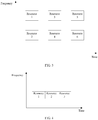
- the network device configures, for the terminal device in advance, a plurality of resources used to transmit uplink control information. As shown in FIG. 5 , within a same time unit, the network device configures four resource blocks, namely, a resource 1 to a resource 4, of different frequency resources for the terminal device. The terminal device may be notified of the configured resources in advance by using higher layer signaling.
- the network device determines, for the terminal device, a resource used for sending the uplink control information. In this case, in this embodiment of this application, the network device performs configuration as much as possible to send an uplink control information on these resources to utilize an allocated resource as much as possible to improve resource utilization.
- the network device may perform configuration as much as possible to repeatedly send an uplink control information on an allocated resource.
- a specific configured repeat count may be determined by the network device based on factors such as quality of an uplink control channel of the terminal device and a reliability requirement reported by the terminal device. For example, if the terminal device has a relatively low reliability requirement, the network device may perform configuration so that the terminal device sends uplink control information only on a particular resource and does not need to repeatedly send the uplink control information. If the terminal device has a relatively high reliability requirement, the network device may perform configuration so that the terminal device repeatedly sends the uplink control information on a plurality of resources.
- uplink control information is repeatedly sent on a resource 1 and a resource 3 shown in FIG. 5
- uplink control information is repeatedly sent on a resource 2 and a resource 4 shown in FIG. 5
- these are both examples of repeated sending in frequency domain.
- the network device sends indication information of the uplink control channel to the terminal device, and the terminal device receives the indication information from the network device.
- the indication information indicates at least one parameter of the following parameters: a time domain length parameter, a frequency domain length parameter, a time domain repeat count parameter, a frequency domain repeat count parameter, and a transmit diversity manner parameter.
- the indication information may be used to indicate at least one parameter of the following parameters: a time domain length parameter, a frequency domain length parameter, a time domain repeat count parameter, a frequency domain repeat count parameter, a power parameter, a transmit diversity manner parameter, a time domain resource parameter, a frequency domain resource parameter, and a sequence resource parameter.
- the network device generates the indication information after configuring the uplink control channel.
- the indication information is a configuration result of the network device.
- the network device sends the indication information to the terminal device for the terminal device to determine a configuration of the uplink control channel.
- the network device may send the indication information to the terminal device by using downlink control information (downlink control information, DCI).
- DCI downlink control information
- the indication information may include the first-format information, and the first-format information includes the at least one parameter as described previously.
- the network device may further notify the terminal device of a plurality of pieces of configured format information in advance, and before the sending, by the network device, indication information of the uplink control channel to the terminal device, the network device may send radio resource control (radio resource control, RRC) signaling or a media access control control element (media access control control element, MCE) to the terminal device.
- RRC radio resource control
- MCE media access control control element
- the network device may notify the terminal device of one or more of the time domain length parameter, the frequency domain length parameter, the time domain repeat count parameter, the frequency domain repeat count parameter, the time domain resource parameter, the frequency domain resource parameter, and the like, to enable the terminal device to correspondingly determine values of the rest parameters.
- the network device does not need to notify the terminal device of excessive parameters in the indication information, so that transmission resources can be further saved.
- format information 1 of the plurality of pieces of format information occupies two symbols when there is no repeated transmission.
- the network device uses the indication information to instruct the terminal device to send uplink control information having a length of four symbols, that is, it is indicated in the indication information that a value of the time domain length parameter is 4.
- the terminal device may determine that a time domain repeat count for sending the uplink control information is 2.
- the network device uses RRC signaling or an MCE to notify the terminal device of the plurality of pieces of format information and also instruct the terminal device to select the format information 1 from the plurality of pieces of format information.
- the format information 1 is repeated twice in time domain and is understood as the first-format information.
- the network device notifies the terminal device that the time domain repeat count for sending the uplink control information is 2.
- the terminal device may determine that the uplink control information having a length of four symbols needs to be sent.
- the indication information may be used to indicate the M parameters, for example, used to indicate the time domain repeat count parameter or the frequency domain repeat count parameter.
- the network device needs to notify the terminal device of format information (namely, second-format information) of the second format in advance.
- format information namely, second-format information
- the network device may use signaling such as RRC signaling or an MCE to indicate the second-format information to the terminal device.
- the second format is an existing PDCCH format such as a PDCCH format 1a in an LTE system, actually the terminal device already knows the second format.
- the network device may not need to send the second-format information to the terminal device again, but needs to send resource information that is of the second format and that is indicated by the second-format information to the terminal device.
- the network device may indicate the resource information of the second format to the terminal device by using signaling such as RRC signaling or an MCE.
- the resource information of the second format may include a resource location of the second format.
- the resource information of the second format includes second-format information about a time resource and/or frequency resource occupied by a PUCCH.
- a same format may correspond to a plurality of resources.
- the terminal device may determine the resource location of the second format based on the resource information of the second format. If the resource information of the second format includes a plurality of different PUCCH resources, the network device may further use dynamic signaling (for example, DCI) to notify the terminal device of a particular PUCCH resource to be selected for transmission.
- DCI dynamic signaling
- the network device configures the uplink control channel in Manner 2 and the M parameters include the time domain repeat count parameter, a value of the time domain repeat count parameter and a location of a start time domain resource may be used to determine a time domain repeat count corresponding to the second format and a corresponding time domain location.
- the location of the start time domain resource may be indicated by the resource information of the second format.
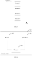
- the network device preconfigures the resource information of the second format for the terminal device, as shown by a resource 1 in the figure.
- the network device notifies the terminal device of a time domain repeat count, for example, 3, according to a reliability requirement that the terminal device needs to satisfy.
- the terminal device sends the uplink control information twice sequentially on a resource 2 and a resource 3 in time domain by using the resource 1 as a start point.
- the time domain repeat count is consecutive or may be nonconsecutive. This is not limited herein. In FIG. 4 , that the repeat count is consecutive in time domain is used as an example.
- the network device needs to send a value of the frequency domain repeat count parameter to the terminal device by using indication information.
- indication information Several optional notification manners are described below.
- the network device sequentially numbers pre-allocated resource blocks, and "0" or "1" in a bitmap indicates whether a resource block is used for information transmission.
- FIG. 5 shows four resource blocks pre-allocated by the network device, and the indication information may use a four-bit bitmap for indication. If the bitmap indicates 0101, it represents that a resource 2 and a resource 4 are used to send the uplink control information; or if the bitmap indicates 0001, it represents that a resource 4 is used to send the uplink control information. Such an indication manner is relatively intuitive.
- the network device establishes a correspondence between the value of the frequency domain repeat count parameter and a resource in advance. For example, if the value of the frequency domain repeat count parameter is 2, correspondingly a resource 1 and a resource 3 are used for sending. If the value of the frequency domain repeat count parameter is 1, correspondingly a resource 2 is used for sending.
- the network device may send the correspondence to the terminal device in advance. The network device only needs to send the value of the frequency domain repeat count parameter to the terminal device in the indication information. After receiving the value of the frequency domain repeat count parameter, the terminal device may determine, based on the correspondence, which resource is used for sending.
- the network device pre-allocates consecutive frequency domain resources. For example, arrangement starts with a resource block 1 for different repeat counts.
- the value of the frequency domain repeat count parameter is 1, it represents that six consecutive physical resource blocks (physical resource block, PRB) starting from the resource block 1 are occupied.
- PRB physical resource block
- the value of the frequency domain repeat count parameter is 2, it represents that 12 consecutive PRBs starting from the resource block 1 are occupied. The rest is deduced by analogy.
- the network device establishes a correspondence between the value of the frequency domain repeat count parameter, a location of a start frequency domain resource, and a resource in advance. For example, when the value of the frequency domain repeat count parameter is 2, a corresponding state is a resource at a location of a start frequency domain resource plus a resource whose sequence number is at an interval of 1 from a sequence number of the start frequency domain resource. For example, a start resource is 1, and correspondingly a resource 1 and a resource 3 are used for sending (where sequence numbers of the resource 1 and the resource 3 are at an interval of 1 from each other).
- a corresponding state is a resource whose location number equals a location number of a start frequency domain resource plus 1 and a resource whose sequence number is at an interval of 2 from the sequence number of the resource.
- a start resource is 1, and correspondingly a resource 2 and a resource 4 are used for sending (where a sequence number of the resource 2 is a sequence number of the resource at the location of the start frequency domain resource plus 1, and sequence numbers of the resource 4 and resource 2 are at an interval of 2 from each other).
- the network device may send the correspondence to the terminal device in advance. The network device only needs to send the value of the frequency domain repeat count parameter to the terminal device in the indication information. After receiving the value of the frequency domain repeat count parameter, the terminal device may determine, based on the correspondence, which resource is used for sending.
- the indication manners described above are applicable to a case in which the network device pre-allocates nonconsecutive frequency domain resources, and are also applicable to a case in which the network device pre-allocates consecutive frequency domain resources.
- the network device may use an indication manner described below other than any of the foregoing manners for indication.
- the network device may alternatively use a resource block length for indication. For example, arrangement starts with a resource block 1 for different repeat counts. When a resource block length is 1, it represents that the resource block 1 is occupied. When the resource block length is 2, it represents that two consecutive PRBs starting with the resource block 1 are occupied. The rest is deduced by analogy.
- the network device configures the uplink control channel in Manner 1
- the first-format information includes the frequency domain repeat count parameter
- the terminal device may determine the value of the frequency domain repeat count parameter based on the first-format information, so that the terminal device may determine locations of all frequency domain resources occupied by the uplink control channel.
- the terminal device sends the uplink control information to the network device according to the indication information by using the uplink control channel, and the network device receives the uplink control information from the terminal device according to the indication information by using the uplink control channel.
- the indication information indicates first-format information and the first-format information includes the value of the frequency domain repeat count parameter, or the indication information indicates M parameters and the M parameters include the frequency domain repeat count parameter.
- the terminal device may send, at the frequency domain location indicated by the frequency domain repeat count parameter, the uplink control information on the uplink control channel based on the frequency domain repeat count indicated by the frequency domain repeat count parameter.
- the network device receives, at the frequency domain location indicated by the frequency domain repeat count parameter, the uplink control information on the uplink control channel based on the frequency domain repeat count indicated by the frequency domain repeat count parameter.
- the indication information indicates first-format information
- the first-format information includes the value of the time domain repeat count parameter
- the indication information indicates M parameters and the M parameters include the time domain repeat count parameter.
- the terminal device may send, at the time domain location indicated by the time domain repeat count parameter, the uplink control information to the network device on the uplink control channel based on the time domain repeat count indicated by the time domain repeat count parameter.
- the network device receives, at the time domain location indicated by the time domain repeat count parameter and on the uplink control channel based on the time domain repeat count indicated by the time domain repeat count parameter, the uplink control information sent by the terminal device.
- the indication information indicates first-format information and the first-format information includes the value of the power parameter, or the indication information indicates M parameters and the M parameters include the power parameter.
- the terminal device may send the uplink control information to the network device on the uplink control channel based on an uplink transmit power indicated by the power parameter.
- the network device receives, on the uplink control channel based on the uplink transmit power indicated by the power parameter, the uplink control information sent by the terminal device.
- the network device may alternatively choose to notify the terminal device of the configuration of the uplink control channel in an implicit manner. It is described in the background of this application that reliability of an uplink control channel and reliability of a downlink channel may be interchanged. Therefore, the network device and the terminal device may agree in advance a rule for reliability interchange between an uplink control channel and a downlink channel. The terminal device may determine reliability of a downlink channel based on a repeat count of the downlink channel.
- the terminal device may correspondingly determine a reliability requirement of an uplink control channel or a time domain repeat count or a frequency domain repeat count of an uplink control channel according to the pre-agreed reliability interchange rule. If the network device configures a plurality of pieces of format information for the terminal device, different pieces of format information may correspond to different reliability requirements or time domain repeat counts or frequency domain repeat counts, and the terminal device may determine the first-format information. Alternatively, if the network device preconfigures the fixed second-format information, the terminal device determines the configuration of the uplink control channel after determining the reliability requirement of the uplink control channel or the time domain repeat count or the frequency domain repeat count of the uplink control channel. In this way, the network device does not need to use additional signaling to notify the terminal device of a related sending parameter of the uplink control channel, thereby reducing signaling overheads.
- the network device may configure an uplink control channel based on factors such as a coverage case and a reliability requirement, so that the configured uplink control channel better satisfies a requirement of a scenario.
- the configuration manner is relatively flexible and is easy to implement.
- FIG. 6 is a schematic structural diagram of a network device 600.
- the network device 600 can implement the functions of the foregoing network device.
- the network device 600 may include a transmitter 601 and a receiver 602.
- the transmitter 601 may be configured to perform S22 in the embodiment shown in FIG. 2 and/or configured to support another process of the technologies described in this specification.
- the receiver 602 may be configured to perform S23 in the embodiment shown in FIG. 2 and/or configured to support another process of the technologies described in this specification.
- the network device 600 may further include a processor 603.
- the processor 603 may be configured to perform S21 in the embodiment shown in FIG.
- the 2 may be configured to generate the indication information, the RRC signaling, the MCE, or the like; may be further configured to preconfigure the plurality of pieces of format information, the second-format information or the like; and/or may be configured to support another process of the technologies described in this specification.
- the steps in the foregoing method embodiment refer to description of functions of corresponding function modules. Details are not described herein again.
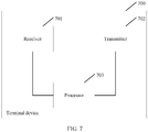
- FIG. 7 is a schematic structural diagram of a terminal device 700.
- the terminal device 700 can implement the functions of the foregoing terminal device.
- the terminal device 700 may include a receiver 701 and a transmitter 702.
- the receiver 701 may be configured to perform S22 in the embodiment shown in FIG. 2 and/or configured to support another process of the technologies described in this specification.
- the transmitter 702 may be configured to perform S23 in the embodiment shown in FIG. 2 and/or configured to support another process of the technologies described in this specification.
- the terminal device 700 may further include a processor 703, configured to determine the first-format information according to the indication information, or determine the second-format information and the M parameters according to the indication information, that is, determine the configuration of the uplink control channel according to the indication information, and/or configured to support another process of the technologies described in this specification.
- a processor 703 configured to determine the first-format information according to the indication information, or determine the second-format information and the M parameters according to the indication information, that is, determine the configuration of the uplink control channel according to the indication information, and/or configured to support another process of the technologies described in this specification.
- the network device 600 and the terminal device 700 are presented in a form of dividing various function modules corresponding to various functions, or may be presented in a form of dividing various function modules in an integrated manner.
- the "module” herein may refer to an application-specific integrated circuit (application-specific integrated circuit, ASIC), a processor that executes one or more software or firmware programs, a memory, an integrated logic circuit, and/or another component capable of providing the foregoing functions.
- ASIC application-specific integrated circuit
- the network device 600 or the terminal device 700 may be implemented by using a structure of a communications apparatus 800 shown in FIG. 8 .
- the communications apparatus 800 may include a memory 801, a processor 802, and a communications interface 803.
- the memory 801 and the communications interface 803 are connected to the processor 802.
- the memory 801 is configured to store a computer executable instruction.
- the processor 802 executes the computer executable instruction stored in the memory 801, so that the communications apparatus 800 performs the method provided in the embodiment shown in FIG. 2 .
- the communications interface 803 may be implemented by using a transceiver or implemented by using a receiver and a transmitter that are independent of each other.
- the transmitter 601 and the receiver 602 may correspond to the communications interface 803 in FIG. 8 .
- the processor 603 may be embedded in or independent of the memory 801 of the communications apparatus 800 in a hardware/software form.
- the receiver 701 and the transmitter 702 may correspond to the communications interface 803 in FIG. 8 .
- the processor 703 may be embedded in or independent of the memory 801 of the communications apparatus 800 in a hardware/software form.
- the communications apparatus 800 may be a field-programmable gate array (field-programmable gate array, FPGA), an application-specific integrated circuit (application-specific integrated circuit, ASIC), a system on chip (system on chip, SoC), a central processing unit (central processing unit, CPU), a network processor (network processor, NP), a digital signal processor (digital signal processor, DSP), a microcontroller unit (microcontroller unit, MCU), a programmable logic device (programmable logic device, PLD), or another integrated chip.
- the communications apparatus 800 may be a separate network element, and is, for example, the terminal device or the network device as described previously.
- the network device provided in the embodiment shown in FIG. 6 may be implemented in another form.
- the network device includes a sending unit and a receiving unit.
- the network device may further include a processing unit.
- the sending unit may be configured to perform S22 in the embodiment shown in FIG. 2 and/or configured to support another process of the technologies described in this specification.
- the receiving unit may be configured to perform S23 in the embodiment shown in FIG. 2 and/or configured to support another process of the technologies described in this specification.
- the processing unit may be configured to perform S21 in the embodiment shown in FIG.
- the 2 may be configured to generate the indication information, the RRC signaling, the MCE, or the like; may be further configured to preconfigure the plurality of pieces of format information, the second-format information or the like; and/or may be configured to support another process of the technologies described in this specification.
- the steps in the foregoing method embodiment refer to description of functions of corresponding function modules. Details are not described herein again.
- the terminal device provided in the embodiment shown in FIG 7 may be implemented in another form.
- the terminal device includes a receiving unit and a sending unit.
- the terminal device may further include a processing unit.
- the receiving unit may be configured to perform S22 in the embodiment shown in FIG. 2 and/or configured to support another process of the technologies described in this specification.
- the sending unit may be configured to perform S23 in the embodiment shown in FIG. 2 and/or configured to support another process of the technologies described in this specification.
- the processing unit is configured to determine the first-format information according to the indication information, or determine the second-format information and the M parameters according to the indication information, that is, determine the configuration of the uplink control channel according to the indication information; and/or configured to support another process of the technologies described in this specification.
- the network device 600, the terminal device 700, and the communications apparatus 800 provided in the embodiments of this application may be configured to perform the methods provided in the embodiment shown in FIG. 2 . Therefore, for technical effects that can be achieved by the network device 600, the terminal device 700, and the communications apparatus 800, refer to the foregoing method embodiment. Details are not described herein again.
- These computer program instructions may be provided for a general purpose computer, a dedicated computer, an embedded processor or a processor of another programmable data processing device to generate a machine, so that the instructions executed by the computer or the processor of the another programmable data processing device generate an apparatus for implementing a specific function in one or more processes in the flowcharts and/or in one or more blocks in the block diagrams.
- All or some of the foregoing embodiments may be implemented by using software, hardware, firmware, or any combination thereof.
- the embodiments each may be implemented completely or partially in a form of a computer program product.
- the computer program product includes one or more computer instructions.
- the computer may be a general purpose computer, a dedicated computer, a computer network, or another programmable apparatus.
- the computer instruction may be stored in a computer readable storage medium or may be transmitted from a computer readable storage medium to another readable storage medium.
- the computer instruction may be transmitted from a website, computer, server, or data center to another website, computer, server or data center in a wired (for example, a coaxial cable, an optical fiber, or a digital subscriber line (DSL)) or wirelessly (for example, infrared, radio, or microwave).
- the computer readable storage medium may be any usable medium accessible by a computer, or a data storage device, such as a server or a data center, integrating one or more usable media.
- the usable medium may be a magnetic medium (for example, a floppy disk, a hard disk, or a magnetic tape), an optical medium (for example, a DVD), a semiconductor medium (for example, a solid-state drive (Solid-State Disk, SSD)), or the like.
- a magnetic medium for example, a floppy disk, a hard disk, or a magnetic tape
- an optical medium for example, a DVD
- a semiconductor medium for example, a solid-state drive (Solid-State Disk, SSD)
Landscapes
- Engineering & Computer Science (AREA)
- Signal Processing (AREA)
- Computer Networks & Wireless Communication (AREA)
- Quality & Reliability (AREA)
- Mobile Radio Communication Systems (AREA)
Applications Claiming Priority (2)
| Application Number | Priority Date | Filing Date | Title |
|---|---|---|---|
| CN201710677555.3A CN109392113B (zh) | 2017-08-09 | 2017-08-09 | 一种接收控制信息、发送控制信息的方法及设备 |
| PCT/CN2018/098687 WO2019029463A1 (zh) | 2017-08-09 | 2018-08-03 | 一种接收控制信息、发送控制信息的方法及设备 |
Publications (3)
| Publication Number | Publication Date |
|---|---|
| EP3661299A1 true EP3661299A1 (de) | 2020-06-03 |
| EP3661299A4 EP3661299A4 (de) | 2020-07-15 |
| EP3661299B1 EP3661299B1 (de) | 2021-11-17 |
Family
ID=65273345
Family Applications (1)
| Application Number | Title | Priority Date | Filing Date |
|---|---|---|---|
| EP18844741.1A Active EP3661299B1 (de) | 2017-08-09 | 2018-08-03 | Verfahren und vorrichtung zum empfangen von steuerinformationen und zum senden von steuerinformationen |
Country Status (5)
| Country | Link |
|---|---|
| US (1) | US11395272B2 (de) |
| EP (1) | EP3661299B1 (de) |
| CN (1) | CN109392113B (de) |
| BR (1) | BR112020002455A2 (de) |
| WO (1) | WO2019029463A1 (de) |
Cited By (1)
| Publication number | Priority date | Publication date | Assignee | Title |
|---|---|---|---|---|
| EP4277185A4 (de) * | 2021-01-08 | 2024-07-10 | China Telecom Corporation Limited | Verfahren, vorrichtung und system zur anzeige und erfassung der anzahl wiederholter pucch-übertragungen |
Families Citing this family (7)
| Publication number | Priority date | Publication date | Assignee | Title |
|---|---|---|---|---|
| CN111277384B (zh) * | 2019-02-27 | 2021-09-14 | 维沃移动通信有限公司 | 传输资源指示方法、传输方法、网络设备和终端 |
| CN111918333B (zh) * | 2019-05-07 | 2023-10-24 | 成都华为技术有限公司 | 数据传输方法和设备 |
| US12408178B2 (en) | 2020-03-06 | 2025-09-02 | Beijing Xiaomi Mobile Software Co., Ltd. | Downlink control channel transmission method and apparatus, terminal and access network device |
| WO2022027649A1 (zh) * | 2020-08-07 | 2022-02-10 | Oppo广东移动通信有限公司 | 时间精度指示方法及装置、终端设备、网络设备 |
| CN114946241B (zh) * | 2020-12-17 | 2026-03-20 | 北京小米移动软件有限公司 | 传输pucch的方法、装置、通信设备及存储介质 |
| WO2022151380A1 (zh) * | 2021-01-15 | 2022-07-21 | 华为技术有限公司 | 传输pucch的方法及装置 |
| CN121621013A (zh) * | 2023-11-22 | 2026-03-06 | 北京小米移动软件有限公司 | 信息处理方法、装置及存储介质 |
Family Cites Families (11)
| Publication number | Priority date | Publication date | Assignee | Title |
|---|---|---|---|---|
| CN101969685B (zh) * | 2010-09-30 | 2015-11-25 | 中兴通讯股份有限公司 | 一种物理上行控制信道的功率设置方法及用户设备 |
| EP2564611B1 (de) * | 2011-07-01 | 2015-02-18 | Ofinno Technologies, LLC | Synchronisationssignal- und Steuerungsmeldungen in Mehrträger-OFDM |
| US9258820B2 (en) * | 2011-11-14 | 2016-02-09 | Blackberry Limited | Method and system for requesting a service utilizing a sequence of codes |
| CN103209483B (zh) * | 2012-01-12 | 2015-09-09 | 华为技术有限公司 | 传输上行控制信息的方法、用户设备和基站 |
| CN109921885B (zh) * | 2012-04-20 | 2021-11-26 | 北京三星通信技术研究有限公司 | 支持发送分集和信道选择的分配harq-ack信道资源的方法 |
| CN103916867A (zh) * | 2012-12-31 | 2014-07-09 | 中国移动通信集团设计院有限公司 | 一种确定控制信道容量的方法和装置 |
| EP3214793B1 (de) * | 2014-10-30 | 2019-06-26 | LG Electronics Inc. | Pucch-übertragungsverfahren durch mtc-vorrichtung |
| CN106162888B (zh) * | 2015-04-10 | 2022-11-08 | 夏普株式会社 | 载波聚合中的pucch资源配置方法及其设备 |
| US10038521B2 (en) * | 2015-08-12 | 2018-07-31 | Lg Electronics Inc. | Method for transmitting control information and an apparatus therefor |
| CN106559841B (zh) * | 2015-09-25 | 2020-03-06 | 北京大学 | 一种lte上行物理控制信道pucch资源的分配方法和装置 |
| EP3592065B1 (de) * | 2017-03-20 | 2021-09-01 | Guangdong Oppo Mobile Telecommunications Corp., Ltd. | Verfahren zur übertragung von daten, und endgerätevorrichtung |
-
2017
- 2017-08-09 CN CN201710677555.3A patent/CN109392113B/zh active Active
-
2018
- 2018-08-03 BR BR112020002455-4A patent/BR112020002455A2/pt unknown
- 2018-08-03 EP EP18844741.1A patent/EP3661299B1/de active Active
- 2018-08-03 WO PCT/CN2018/098687 patent/WO2019029463A1/zh not_active Ceased
-
2020
- 2020-02-05 US US16/783,157 patent/US11395272B2/en active Active
Cited By (2)
| Publication number | Priority date | Publication date | Assignee | Title |
|---|---|---|---|---|
| EP4277185A4 (de) * | 2021-01-08 | 2024-07-10 | China Telecom Corporation Limited | Verfahren, vorrichtung und system zur anzeige und erfassung der anzahl wiederholter pucch-übertragungen |
| US12200712B2 (en) | 2021-01-08 | 2025-01-14 | China Telecom Corporation Limited | Method, device and system for indicating and obtaining number of pucch repetitions |
Also Published As
| Publication number | Publication date |
|---|---|
| BR112020002455A2 (pt) | 2020-07-28 |
| US20200178248A1 (en) | 2020-06-04 |
| EP3661299B1 (de) | 2021-11-17 |
| CN109392113B (zh) | 2022-09-02 |
| EP3661299A4 (de) | 2020-07-15 |
| CN109392113A (zh) | 2019-02-26 |
| US11395272B2 (en) | 2022-07-19 |
| WO2019029463A1 (zh) | 2019-02-14 |
Similar Documents
| Publication | Publication Date | Title |
|---|---|---|
| US11832089B2 (en) | Systems and methods for multicast resource allocation | |
| US11985688B2 (en) | Transmission direction configuration method, device, and system | |
| US11849463B2 (en) | Method and apparatus for supporting multiple services in advanced MIMO communication systems | |
| US12089229B2 (en) | PDCCH monitoring periodicity | |
| US11395272B2 (en) | Method and device for receiving and sending control information | |
| CN110691416B (zh) | 一种资源调度的方法和装置 | |
| US10785010B2 (en) | Wireless communications method and apparatus | |
| US20200068610A1 (en) | Resource scheduling method, network device, and communications device | |
| US20190098590A1 (en) | Method and apparatus for control resource set configuration for common control | |
| US12376076B2 (en) | Methods and apparatus for resource reservation in narrowband Internet of Things communications | |
| CN115777222A (zh) | 具有码元掩码的控制消息 | |
| US20240323952A1 (en) | Terminal device, base station device, and communication method | |
| KR102935566B1 (ko) | 무선 통신 시스템에서 사이드링크 송수신 방법 및 이에 대한 장치 |
Legal Events
| Date | Code | Title | Description |
|---|---|---|---|
| STAA | Information on the status of an ep patent application or granted ep patent |
Free format text: STATUS: THE INTERNATIONAL PUBLICATION HAS BEEN MADE |
|
| PUAI | Public reference made under article 153(3) epc to a published international application that has entered the european phase |
Free format text: ORIGINAL CODE: 0009012 |
|
| STAA | Information on the status of an ep patent application or granted ep patent |
Free format text: STATUS: REQUEST FOR EXAMINATION WAS MADE |
|
| 17P | Request for examination filed |
Effective date: 20200224 |
|
| AK | Designated contracting states |
Kind code of ref document: A1 Designated state(s): AL AT BE BG CH CY CZ DE DK EE ES FI FR GB GR HR HU IE IS IT LI LT LU LV MC MK MT NL NO PL PT RO RS SE SI SK SM TR |
|
| AX | Request for extension of the european patent |
Extension state: BA ME |
|
| A4 | Supplementary search report drawn up and despatched |
Effective date: 20200616 |
|
| RIC1 | Information provided on ipc code assigned before grant |
Ipc: H04W 72/04 20090101AFI20200609BHEP |
|
| DAV | Request for validation of the european patent (deleted) | ||
| DAX | Request for extension of the european patent (deleted) | ||
| RIC1 | Information provided on ipc code assigned before grant |
Ipc: H04L 1/00 20060101ALI20210421BHEP Ipc: H04W 72/04 20090101AFI20210421BHEP |
|
| GRAP | Despatch of communication of intention to grant a patent |
Free format text: ORIGINAL CODE: EPIDOSNIGR1 |
|
| STAA | Information on the status of an ep patent application or granted ep patent |
Free format text: STATUS: GRANT OF PATENT IS INTENDED |
|
| INTG | Intention to grant announced |
Effective date: 20210610 |
|
| GRAS | Grant fee paid |
Free format text: ORIGINAL CODE: EPIDOSNIGR3 |
|
| GRAA | (expected) grant |
Free format text: ORIGINAL CODE: 0009210 |
|
| STAA | Information on the status of an ep patent application or granted ep patent |
Free format text: STATUS: THE PATENT HAS BEEN GRANTED |
|
| AK | Designated contracting states |
Kind code of ref document: B1 Designated state(s): AL AT BE BG CH CY CZ DE DK EE ES FI FR GB GR HR HU IE IS IT LI LT LU LV MC MK MT NL NO PL PT RO RS SE SI SK SM TR |
|
| REG | Reference to a national code |
Ref country code: GB Ref legal event code: FG4D |
|
| REG | Reference to a national code |
Ref country code: IE Ref legal event code: FG4D |
|
| REG | Reference to a national code |
Ref country code: DE Ref legal event code: R096 Ref document number: 602018026971 Country of ref document: DE |
|
| REG | Reference to a national code |
Ref country code: AT Ref legal event code: REF Ref document number: 1449076 Country of ref document: AT Kind code of ref document: T Effective date: 20211215 |
|
| REG | Reference to a national code |
Ref country code: LT Ref legal event code: MG9D |
|
| REG | Reference to a national code |
Ref country code: NL Ref legal event code: MP Effective date: 20211117 |
|
| REG | Reference to a national code |
Ref country code: AT Ref legal event code: MK05 Ref document number: 1449076 Country of ref document: AT Kind code of ref document: T Effective date: 20211117 |
|
| PG25 | Lapsed in a contracting state [announced via postgrant information from national office to epo] |
Ref country code: RS Free format text: LAPSE BECAUSE OF FAILURE TO SUBMIT A TRANSLATION OF THE DESCRIPTION OR TO PAY THE FEE WITHIN THE PRESCRIBED TIME-LIMIT Effective date: 20211117 Ref country code: LT Free format text: LAPSE BECAUSE OF FAILURE TO SUBMIT A TRANSLATION OF THE DESCRIPTION OR TO PAY THE FEE WITHIN THE PRESCRIBED TIME-LIMIT Effective date: 20211117 Ref country code: FI Free format text: LAPSE BECAUSE OF FAILURE TO SUBMIT A TRANSLATION OF THE DESCRIPTION OR TO PAY THE FEE WITHIN THE PRESCRIBED TIME-LIMIT Effective date: 20211117 Ref country code: BG Free format text: LAPSE BECAUSE OF FAILURE TO SUBMIT A TRANSLATION OF THE DESCRIPTION OR TO PAY THE FEE WITHIN THE PRESCRIBED TIME-LIMIT Effective date: 20220217 Ref country code: AT Free format text: LAPSE BECAUSE OF FAILURE TO SUBMIT A TRANSLATION OF THE DESCRIPTION OR TO PAY THE FEE WITHIN THE PRESCRIBED TIME-LIMIT Effective date: 20211117 |
|
| PG25 | Lapsed in a contracting state [announced via postgrant information from national office to epo] |
Ref country code: IS Free format text: LAPSE BECAUSE OF FAILURE TO SUBMIT A TRANSLATION OF THE DESCRIPTION OR TO PAY THE FEE WITHIN THE PRESCRIBED TIME-LIMIT Effective date: 20220317 Ref country code: SE Free format text: LAPSE BECAUSE OF FAILURE TO SUBMIT A TRANSLATION OF THE DESCRIPTION OR TO PAY THE FEE WITHIN THE PRESCRIBED TIME-LIMIT Effective date: 20211117 Ref country code: PT Free format text: LAPSE BECAUSE OF FAILURE TO SUBMIT A TRANSLATION OF THE DESCRIPTION OR TO PAY THE FEE WITHIN THE PRESCRIBED TIME-LIMIT Effective date: 20220317 Ref country code: PL Free format text: LAPSE BECAUSE OF FAILURE TO SUBMIT A TRANSLATION OF THE DESCRIPTION OR TO PAY THE FEE WITHIN THE PRESCRIBED TIME-LIMIT Effective date: 20211117 Ref country code: NO Free format text: LAPSE BECAUSE OF FAILURE TO SUBMIT A TRANSLATION OF THE DESCRIPTION OR TO PAY THE FEE WITHIN THE PRESCRIBED TIME-LIMIT Effective date: 20220217 Ref country code: NL Free format text: LAPSE BECAUSE OF FAILURE TO SUBMIT A TRANSLATION OF THE DESCRIPTION OR TO PAY THE FEE WITHIN THE PRESCRIBED TIME-LIMIT Effective date: 20211117 Ref country code: LV Free format text: LAPSE BECAUSE OF FAILURE TO SUBMIT A TRANSLATION OF THE DESCRIPTION OR TO PAY THE FEE WITHIN THE PRESCRIBED TIME-LIMIT Effective date: 20211117 Ref country code: HR Free format text: LAPSE BECAUSE OF FAILURE TO SUBMIT A TRANSLATION OF THE DESCRIPTION OR TO PAY THE FEE WITHIN THE PRESCRIBED TIME-LIMIT Effective date: 20211117 Ref country code: GR Free format text: LAPSE BECAUSE OF FAILURE TO SUBMIT A TRANSLATION OF THE DESCRIPTION OR TO PAY THE FEE WITHIN THE PRESCRIBED TIME-LIMIT Effective date: 20220218 Ref country code: ES Free format text: LAPSE BECAUSE OF FAILURE TO SUBMIT A TRANSLATION OF THE DESCRIPTION OR TO PAY THE FEE WITHIN THE PRESCRIBED TIME-LIMIT Effective date: 20211117 |
|
| PG25 | Lapsed in a contracting state [announced via postgrant information from national office to epo] |
Ref country code: SM Free format text: LAPSE BECAUSE OF FAILURE TO SUBMIT A TRANSLATION OF THE DESCRIPTION OR TO PAY THE FEE WITHIN THE PRESCRIBED TIME-LIMIT Effective date: 20211117 Ref country code: SK Free format text: LAPSE BECAUSE OF FAILURE TO SUBMIT A TRANSLATION OF THE DESCRIPTION OR TO PAY THE FEE WITHIN THE PRESCRIBED TIME-LIMIT Effective date: 20211117 Ref country code: RO Free format text: LAPSE BECAUSE OF FAILURE TO SUBMIT A TRANSLATION OF THE DESCRIPTION OR TO PAY THE FEE WITHIN THE PRESCRIBED TIME-LIMIT Effective date: 20211117 Ref country code: DK Free format text: LAPSE BECAUSE OF FAILURE TO SUBMIT A TRANSLATION OF THE DESCRIPTION OR TO PAY THE FEE WITHIN THE PRESCRIBED TIME-LIMIT Effective date: 20211117 Ref country code: CZ Free format text: LAPSE BECAUSE OF FAILURE TO SUBMIT A TRANSLATION OF THE DESCRIPTION OR TO PAY THE FEE WITHIN THE PRESCRIBED TIME-LIMIT Effective date: 20211117 |
|
| REG | Reference to a national code |
Ref country code: DE Ref legal event code: R097 Ref document number: 602018026971 Country of ref document: DE |
|
| PLBE | No opposition filed within time limit |
Free format text: ORIGINAL CODE: 0009261 |
|
| STAA | Information on the status of an ep patent application or granted ep patent |
Free format text: STATUS: NO OPPOSITION FILED WITHIN TIME LIMIT |
|
| 26N | No opposition filed |
Effective date: 20220818 |
|
| PG25 | Lapsed in a contracting state [announced via postgrant information from national office to epo] |
Ref country code: AL Free format text: LAPSE BECAUSE OF FAILURE TO SUBMIT A TRANSLATION OF THE DESCRIPTION OR TO PAY THE FEE WITHIN THE PRESCRIBED TIME-LIMIT Effective date: 20211117 |
|
| PG25 | Lapsed in a contracting state [announced via postgrant information from national office to epo] |
Ref country code: SI Free format text: LAPSE BECAUSE OF FAILURE TO SUBMIT A TRANSLATION OF THE DESCRIPTION OR TO PAY THE FEE WITHIN THE PRESCRIBED TIME-LIMIT Effective date: 20211117 |
|
| PG25 | Lapsed in a contracting state [announced via postgrant information from national office to epo] |
Ref country code: MC Free format text: LAPSE BECAUSE OF FAILURE TO SUBMIT A TRANSLATION OF THE DESCRIPTION OR TO PAY THE FEE WITHIN THE PRESCRIBED TIME-LIMIT Effective date: 20211117 |
|
| REG | Reference to a national code |
Ref country code: CH Ref legal event code: PL |
|
| PG25 | Lapsed in a contracting state [announced via postgrant information from national office to epo] |
Ref country code: LU Free format text: LAPSE BECAUSE OF NON-PAYMENT OF DUE FEES Effective date: 20220803 Ref country code: LI Free format text: LAPSE BECAUSE OF NON-PAYMENT OF DUE FEES Effective date: 20220831 Ref country code: CH Free format text: LAPSE BECAUSE OF NON-PAYMENT OF DUE FEES Effective date: 20220831 |
|
| REG | Reference to a national code |
Ref country code: BE Ref legal event code: MM Effective date: 20220831 |
|
| PG25 | Lapsed in a contracting state [announced via postgrant information from national office to epo] |
Ref country code: IT Free format text: LAPSE BECAUSE OF FAILURE TO SUBMIT A TRANSLATION OF THE DESCRIPTION OR TO PAY THE FEE WITHIN THE PRESCRIBED TIME-LIMIT Effective date: 20211117 |
|
| P01 | Opt-out of the competence of the unified patent court (upc) registered |
Effective date: 20230524 |
|
| PG25 | Lapsed in a contracting state [announced via postgrant information from national office to epo] |
Ref country code: IE Free format text: LAPSE BECAUSE OF NON-PAYMENT OF DUE FEES Effective date: 20220803 |
|
| PG25 | Lapsed in a contracting state [announced via postgrant information from national office to epo] |
Ref country code: BE Free format text: LAPSE BECAUSE OF NON-PAYMENT OF DUE FEES Effective date: 20220831 |
|
| PG25 | Lapsed in a contracting state [announced via postgrant information from national office to epo] |
Ref country code: MK Free format text: LAPSE BECAUSE OF FAILURE TO SUBMIT A TRANSLATION OF THE DESCRIPTION OR TO PAY THE FEE WITHIN THE PRESCRIBED TIME-LIMIT Effective date: 20211117 Ref country code: EE Free format text: LAPSE BECAUSE OF FAILURE TO SUBMIT A TRANSLATION OF THE DESCRIPTION OR TO PAY THE FEE WITHIN THE PRESCRIBED TIME-LIMIT Effective date: 20211117 Ref country code: CY Free format text: LAPSE BECAUSE OF FAILURE TO SUBMIT A TRANSLATION OF THE DESCRIPTION OR TO PAY THE FEE WITHIN THE PRESCRIBED TIME-LIMIT Effective date: 20211117 |
|
| PG25 | Lapsed in a contracting state [announced via postgrant information from national office to epo] |
Ref country code: HU Free format text: LAPSE BECAUSE OF FAILURE TO SUBMIT A TRANSLATION OF THE DESCRIPTION OR TO PAY THE FEE WITHIN THE PRESCRIBED TIME-LIMIT; INVALID AB INITIO Effective date: 20180803 |
|
| PG25 | Lapsed in a contracting state [announced via postgrant information from national office to epo] |
Ref country code: TR Free format text: LAPSE BECAUSE OF FAILURE TO SUBMIT A TRANSLATION OF THE DESCRIPTION OR TO PAY THE FEE WITHIN THE PRESCRIBED TIME-LIMIT Effective date: 20211117 |
|
| PG25 | Lapsed in a contracting state [announced via postgrant information from national office to epo] |
Ref country code: MT Free format text: LAPSE BECAUSE OF FAILURE TO SUBMIT A TRANSLATION OF THE DESCRIPTION OR TO PAY THE FEE WITHIN THE PRESCRIBED TIME-LIMIT Effective date: 20211117 |
|
| PGFP | Annual fee paid to national office [announced via postgrant information from national office to epo] |
Ref country code: DE Payment date: 20250702 Year of fee payment: 8 |
|
| PGFP | Annual fee paid to national office [announced via postgrant information from national office to epo] |
Ref country code: GB Payment date: 20250703 Year of fee payment: 8 |
|
| PGFP | Annual fee paid to national office [announced via postgrant information from national office to epo] |
Ref country code: FR Payment date: 20250703 Year of fee payment: 8 |