EP3661341A1 - Dispositif de refroidissement d'un rail conducteur - Google Patents
Dispositif de refroidissement d'un rail conducteur Download PDFInfo
- Publication number
- EP3661341A1 EP3661341A1 EP18208453.3A EP18208453A EP3661341A1 EP 3661341 A1 EP3661341 A1 EP 3661341A1 EP 18208453 A EP18208453 A EP 18208453A EP 3661341 A1 EP3661341 A1 EP 3661341A1
- Authority
- EP
- European Patent Office
- Prior art keywords
- heat
- busbar
- cooling
- elements
- heat absorption
- Prior art date
- Legal status (The legal status is an assumption and is not a legal conclusion. Google has not performed a legal analysis and makes no representation as to the accuracy of the status listed.)
- Withdrawn
Links
- 238000001816 cooling Methods 0.000 title claims abstract description 19
- 238000010521 absorption reaction Methods 0.000 claims abstract description 27
- 230000006835 compression Effects 0.000 claims description 6
- 238000007906 compression Methods 0.000 claims description 6
- 238000009413 insulation Methods 0.000 claims description 6
- 230000000712 assembly Effects 0.000 claims description 3
- 238000000429 assembly Methods 0.000 claims description 3
- 238000003825 pressing Methods 0.000 claims description 2
- 239000004065 semiconductor Substances 0.000 description 8
- RYGMFSIKBFXOCR-UHFFFAOYSA-N Copper Chemical compound [Cu] RYGMFSIKBFXOCR-UHFFFAOYSA-N 0.000 description 4
- 229910052802 copper Inorganic materials 0.000 description 4
- 239000010949 copper Substances 0.000 description 4
- 239000004020 conductor Substances 0.000 description 3
- 238000010292 electrical insulation Methods 0.000 description 2
- 239000011343 solid material Substances 0.000 description 2
- XAGFODPZIPBFFR-UHFFFAOYSA-N aluminium Chemical compound [Al] XAGFODPZIPBFFR-UHFFFAOYSA-N 0.000 description 1
- 229910052782 aluminium Inorganic materials 0.000 description 1
- 239000003990 capacitor Substances 0.000 description 1
- 239000000919 ceramic Substances 0.000 description 1
- 239000011888 foil Substances 0.000 description 1
- 239000004519 grease Substances 0.000 description 1
- 230000017525 heat dissipation Effects 0.000 description 1
- 238000010438 heat treatment Methods 0.000 description 1
- 238000000034 method Methods 0.000 description 1
Images
Classifications
-
- H—ELECTRICITY
- H05—ELECTRIC TECHNIQUES NOT OTHERWISE PROVIDED FOR
- H05K—PRINTED CIRCUITS; CASINGS OR CONSTRUCTIONAL DETAILS OF ELECTRIC APPARATUS; MANUFACTURE OF ASSEMBLAGES OF ELECTRICAL COMPONENTS
- H05K7/00—Constructional details common to different types of electric apparatus
- H05K7/20—Modifications to facilitate cooling, ventilating, or heating
- H05K7/2089—Modifications to facilitate cooling, ventilating, or heating for power electronics, e.g. for inverters for controlling motor
- H05K7/209—Heat transfer by conduction from internal heat source to heat radiating structure
-
- H—ELECTRICITY
- H02—GENERATION; CONVERSION OR DISTRIBUTION OF ELECTRIC POWER
- H02G—INSTALLATION OF ELECTRIC CABLES OR LINES, OR OF COMBINED OPTICAL AND ELECTRIC CABLES OR LINES
- H02G5/00—Installations of bus-bars
- H02G5/10—Cooling
-
- H—ELECTRICITY
- H05—ELECTRIC TECHNIQUES NOT OTHERWISE PROVIDED FOR
- H05K—PRINTED CIRCUITS; CASINGS OR CONSTRUCTIONAL DETAILS OF ELECTRIC APPARATUS; MANUFACTURE OF ASSEMBLAGES OF ELECTRICAL COMPONENTS
- H05K7/00—Constructional details common to different types of electric apparatus
- H05K7/14—Mounting supporting structure in casing or on frame or rack
- H05K7/1422—Printed circuit boards receptacles, e.g. stacked structures, electronic circuit modules or box like frames
- H05K7/1427—Housings
- H05K7/1432—Housings specially adapted for power drive units or power converters
- H05K7/14329—Housings specially adapted for power drive units or power converters specially adapted for the configuration of power bus bars
-
- H—ELECTRICITY
- H05—ELECTRIC TECHNIQUES NOT OTHERWISE PROVIDED FOR
- H05K—PRINTED CIRCUITS; CASINGS OR CONSTRUCTIONAL DETAILS OF ELECTRIC APPARATUS; MANUFACTURE OF ASSEMBLAGES OF ELECTRICAL COMPONENTS
- H05K7/00—Constructional details common to different types of electric apparatus
- H05K7/20—Modifications to facilitate cooling, ventilating, or heating
- H05K7/2039—Modifications to facilitate cooling, ventilating, or heating characterised by the heat transfer by conduction from the heat generating element to a dissipating body
- H05K7/20436—Inner thermal coupling elements in heat dissipating housings, e.g. protrusions or depressions integrally formed in the housing
- H05K7/20445—Inner thermal coupling elements in heat dissipating housings, e.g. protrusions or depressions integrally formed in the housing the coupling element being an additional piece, e.g. thermal standoff
- H05K7/20454—Inner thermal coupling elements in heat dissipating housings, e.g. protrusions or depressions integrally formed in the housing the coupling element being an additional piece, e.g. thermal standoff with a conformable or flexible structure compensating for irregularities, e.g. cushion bags, thermal paste
-
- H—ELECTRICITY
- H02—GENERATION; CONVERSION OR DISTRIBUTION OF ELECTRIC POWER
- H02B—BOARDS, SUBSTATIONS OR SWITCHING ARRANGEMENTS FOR THE SUPPLY OR DISTRIBUTION OF ELECTRIC POWER
- H02B13/00—Arrangement of switchgear in which switches are enclosed in, or structurally associated with, a casing, e.g. cubicle
Definitions
- the invention relates to a device for cooling a busbar.
- Busbars from, to and in power electronics devices, in control cabinets and distribution systems for low and medium voltage exhibit self-heating, which, depending on the dimensioning of the busbar and the current density in the busbar, leads to an increase in temperature.
- the limit for copper busbars is approximately 2.2 A / mm 2 for aluminum busbars is approximately 1.5 A / mm 2 . If these busbars are electrically contacted, for example, with semiconductor modules of a converter of a drive, a heat flow from the busbar into the semiconductor module can be established. This additional heat input, if any, into the semiconductor module can considerably reduce its service life and accordingly lead to failures of the semiconductor module and thus of the converter and its drive.
- the heat loss from the busbars must be dissipated from control cabinets, for example.
- These power electronic devices are, for example, semiconductor modules, capacitors or chokes.
- the heat loss from the conductor rails can also be dissipated passively by increasing the surface area, for example by cooling plates using self-convection.
- the heat loss from the busbars can also be actively dissipated by increasing the surface area, using cooling plates and / or accelerated convection by additional fans.
- a disadvantage of the solutions shown in principle is that the amount of heat loss from the busbars, in addition to the heat generated in the power electronics devices, etc. must be removed from the air. This leads to disadvantages in particular in the case of liquid-cooled power electronic devices, since the amount of heat on the busbars has to be dissipated via air convection in order not to additionally heat up the power electronic devices.
- the object of the invention is to provide a device for cooling a busbar which avoids the disadvantages mentioned above.
- the problem is also solved by using this device for cooling at least one busbar in compact electrical switchgear assemblies with busbar assemblies, in particular control cabinets for converters, low-voltage switchgear and medium-voltage switchgear.
- a heat transport system which has a heat absorption element, a heat transport system and a heat emission element, in order to conduct the heat source, that is to say the conductor rail, in a thermally conductive manner with a heat sink, for example a heat exchanger or another cooler environment.
- Heat absorption element and heat emission element are made in copper due to the comparatively good thermal conductivity.
- the heat transport system can also be designed as copper made of solid material or as a heat pipe.
- the number of devices for cooling the busbar can be made scalable and can thus be modularly adapted to the required heat transfer capacity.
- Welded and soldered connections are suitable for copper in solid material as a thermally conductive connection method between the heat absorption element and the heat emission element and the heat transport system.
- the heat absorption element Since the busbar has potential in normal operation, but the heat absorption element is usually at ground potential, electrical insulation between the heat absorption element and the busbar is therefore required.
- the heat absorption element is covered with an insulation layer. This can be designed as a ceramic heat-conducting film or phase-change film, which contributes to electrical insulation and a simultaneous heat flow.
- the heat emitting element with the heat sink can also be provided with a heat-conducting film, a phase-change film or a Thermal grease to be provided.
- the contact rail elements which now have a large area, such as heat absorption element, heat emission element and sufficient heat transport, cool the busbar comparatively well.
- the heat-absorbing elements and heat-emitting elements are preferably designed to be as flat as possible in order to adapt to the surface of the — generally flat — busbar. In the case of other cross-sectional shapes of the conductor rail, that is to say square, trapezoidal, oval, etc., the heat absorption elements and heat emission elements must be designed accordingly. Minor adjustments to the surface structures of the busbar and / or heat absorption element or heat emission element are also carried out via the heat-conducting foils and / or heat-conducting pastes.
- these heat absorption elements and heat emission elements also allow compensation in the case of heat-related and / or mechanical expansions of the busbar without losing the heat-conducting contact. Among other things, this guaranteed by the pressing elements.
- the device now enables the busbars to be cooled without substantial heat being given off to the surroundings, in particular in a control cabinet. Furthermore, the cooling capacity can be scaled by varying the number and / or type of heat absorption elements, heat emission elements and also heat transport elements.
- the heat emission elements are preferably arranged outside of a control cabinet.
- this device is also particularly suitable for use in liquid-cooled power electronics devices, which means that this device can be installed in control cabinets with a high degree of protection without additional effort.
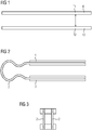
- FIG. 1 shows in a basic representation a heat source with a temperature T1 and a heat sink 12 with a temperature T2.
- T1 is larger than T2.
- the heat from the heat source should be conducted to the heat sink 12.
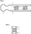
- a heat absorption element 1 which is thermally conductively connected to a heat emission element 3 via a heat transport system 2.
- a plurality of heat absorption elements 1, heat emission element 3 and also a plurality of heat transport systems 2 can be arranged on a busbar 6 in a scalable manner.
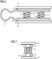
- FIG 4 shows the arrangement according to 2 and 3 with a compression spring 4 between the heat absorption element 1 and the heat emission element 3 in order to obtain an additional contact pressure against certain heat sources and heat sinks in order to improve the heat transfer in each case.
- the compression springs 4 are guided by a guide pin 5. This arrangement allows compensation for heat-related and / or mechanical expansions of the busbar 6 without impairing the heat-conducting contact.
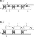
- FIG 6 show the arrangement with compression springs 4 now in use on a busbar 6, which is spaced with an insulation layer 7 from the heat absorbing element 1.
- a heat-conducting paste 9 is provided in order to release the heat from the busbar 6 via the insulation layer 7 to the heat absorption element 1 or from the heat emission element 3 to the heat sink 12.
- the heat sink 12 is designed, for example, as a heat exchanger, which is arranged outside a control cabinet.
- FIG 8 shows such arrangements, for example, within a control cabinet, where a plurality of semiconductor modules 10 are arranged in electrical contact with the busbar 6 and where the busbar 6 is additionally cooled by the arrangement described above.
- the semiconductor modules 10 are advantageously also arranged in a heat-conducting manner taking into account the insulation requirements on a heat sink 12.
- the semiconductor modules 10 can also be directly thermally conductive, taking into account the insulation requirements on the busbar 6 according to FIG. 9 be arranged.
- heat absorption elements 1 can also be guided onto one heat emission element 3.
- a three-phase busbar arrangement each with one or more heat absorption elements 1, conduct their heat to a heat emission element 3, in particular outside of a control cabinet.
- the device for cooling a busbar 6 is particularly suitable for closed, confined spaces in which, above all, power electronics devices, for example converters of comparatively high power, are provided in control cabinets.
- the device for cooling a busbar is also suitable for switchgear in particularly confined spaces Conditions from which the heat is to be removed. These can be switchgear at low and medium voltage levels.
Landscapes
- Engineering & Computer Science (AREA)
- Microelectronics & Electronic Packaging (AREA)
- Physics & Mathematics (AREA)
- Thermal Sciences (AREA)
- Cooling Or The Like Of Electrical Apparatus (AREA)
- Cooling Or The Like Of Semiconductors Or Solid State Devices (AREA)
Priority Applications (5)
| Application Number | Priority Date | Filing Date | Title |
|---|---|---|---|
| EP18208453.3A EP3661341A1 (fr) | 2018-11-27 | 2018-11-27 | Dispositif de refroidissement d'un rail conducteur |
| EP19801717.0A EP3864943B1 (fr) | 2018-11-27 | 2019-10-30 | Dispositif de refroidissement d'un rail conducteur |
| CN201980077956.2A CN113170597A (zh) | 2018-11-27 | 2019-10-30 | 用于冷却汇流排的装置 |
| PCT/EP2019/079586 WO2020108905A1 (fr) | 2018-11-27 | 2019-10-30 | Dispositif de refroidissement d'une barre omnibus |
| US17/297,286 US11990741B2 (en) | 2018-11-27 | 2019-10-30 | Device for cooling a bus bar |
Applications Claiming Priority (1)
| Application Number | Priority Date | Filing Date | Title |
|---|---|---|---|
| EP18208453.3A EP3661341A1 (fr) | 2018-11-27 | 2018-11-27 | Dispositif de refroidissement d'un rail conducteur |
Publications (1)
| Publication Number | Publication Date |
|---|---|
| EP3661341A1 true EP3661341A1 (fr) | 2020-06-03 |
Family
ID=64556660
Family Applications (2)
| Application Number | Title | Priority Date | Filing Date |
|---|---|---|---|
| EP18208453.3A Withdrawn EP3661341A1 (fr) | 2018-11-27 | 2018-11-27 | Dispositif de refroidissement d'un rail conducteur |
| EP19801717.0A Active EP3864943B1 (fr) | 2018-11-27 | 2019-10-30 | Dispositif de refroidissement d'un rail conducteur |
Family Applications After (1)
| Application Number | Title | Priority Date | Filing Date |
|---|---|---|---|
| EP19801717.0A Active EP3864943B1 (fr) | 2018-11-27 | 2019-10-30 | Dispositif de refroidissement d'un rail conducteur |
Country Status (4)
| Country | Link |
|---|---|
| US (1) | US11990741B2 (fr) |
| EP (2) | EP3661341A1 (fr) |
| CN (1) | CN113170597A (fr) |
| WO (1) | WO2020108905A1 (fr) |
Families Citing this family (3)
| Publication number | Priority date | Publication date | Assignee | Title |
|---|---|---|---|---|
| DE102019101973A1 (de) * | 2019-01-28 | 2020-07-30 | Eugen Forschner Gmbh | Verbindungsanordnung zum Verbinden einer Stromschiene mit einem Gehäuse |
| DE102022108334B4 (de) * | 2022-04-06 | 2026-05-28 | Lisa Dräxlmaier GmbH | Stromschiene mit aufnahme für eine kühlung |
| US12456855B2 (en) * | 2022-05-26 | 2025-10-28 | GM Global Technology Operations LLC | Thermally conducting bracket for busbar to cold plate heat transfer |
Citations (4)
| Publication number | Priority date | Publication date | Assignee | Title |
|---|---|---|---|---|
| DE102007003875A1 (de) * | 2007-01-25 | 2008-08-07 | Siemens Ag | Stromrichter |
| EP2356894A1 (fr) * | 2008-12-10 | 2011-08-17 | Siemens Aktiengesellschaft | Module redresseur de courant avec rails refroidis |
| US20120113569A1 (en) * | 2010-11-08 | 2012-05-10 | Schneider Electric USA, Inc. | Heat dissipation means for increasing power density in enclosed equipment |
| US20150124381A1 (en) * | 2013-11-05 | 2015-05-07 | Chia Hsing Electrical Co., Ltd. | Switchboard copper busbar heat dissipating device |
Family Cites Families (18)
| Publication number | Priority date | Publication date | Assignee | Title |
|---|---|---|---|---|
| DE4004457A1 (de) | 1990-02-14 | 1991-08-22 | Telefunken Systemtechnik | Waermesenke fuer ein elektronisches leiterplattenbauelement |
| US5164624A (en) * | 1991-09-06 | 1992-11-17 | General Motors Corporation | Modular power semiconductor assembly for an alternator-fed DC power source |
| DE19603224A1 (de) | 1996-01-30 | 1997-07-31 | Wolfgang Dipl Ing Schuster | Mechanische Anordnung parallelgeschalteter Halbleiterbauelemente |
| JP3106428B2 (ja) | 1996-06-12 | 2000-11-06 | 古河電気工業株式会社 | ヒートシンクおよびその製造方法、並びにヒートシンク付き電子装置およびその製造方法 |
| JP2000022366A (ja) * | 1998-06-30 | 2000-01-21 | Hitachi Denshi Ltd | 熱伝導部材およびその熱伝導部材を用いた冷却構造 |
| US6918438B2 (en) * | 2002-06-04 | 2005-07-19 | International Business Machines Corporation | Finned heat sink |
| CN2843009Y (zh) * | 2005-04-01 | 2006-11-29 | 威盛电子股份有限公司 | 散热模组 |
| US7277291B2 (en) * | 2005-08-08 | 2007-10-02 | Verifone Holdings, Inc. | Thermal transfer device |
| DE102007023980B3 (de) * | 2007-05-23 | 2008-09-25 | Rittal Gmbh & Co. Kg | Stromsammelschienenanordnung |
| TWI325754B (en) * | 2007-08-28 | 2010-06-01 | Inventec Corp | Heat dissipation module |
| CN101776941B (zh) * | 2009-01-08 | 2013-03-13 | 富准精密工业(深圳)有限公司 | 散热装置 |
| US20130043071A1 (en) * | 2011-08-17 | 2013-02-21 | General Electric Company | Thermal energy management component and system incorporating the same |
| CN202254997U (zh) * | 2011-10-11 | 2012-05-30 | 讯凯国际股份有限公司 | 热管、散热模块及照明装置 |
| WO2014132399A1 (fr) * | 2013-02-28 | 2014-09-04 | 三菱電機株式会社 | Structure de dissipation de chaleur |
| ITUB20159292A1 (it) * | 2015-12-16 | 2017-06-16 | Bticino Spa | Condotto a barre. |
| US10283945B2 (en) * | 2016-03-23 | 2019-05-07 | Eaton Intelligent Power Limited | Load center thermally conductive component |
| CN205726824U (zh) * | 2016-04-11 | 2016-11-23 | 中兴通讯股份有限公司 | 散热装置及电路板 |
| US10178813B2 (en) * | 2017-01-26 | 2019-01-08 | The United States Of America As Represented By The Secretary Of The Army | Stacked power module with integrated thermal management |
-
2018
- 2018-11-27 EP EP18208453.3A patent/EP3661341A1/fr not_active Withdrawn
-
2019
- 2019-10-30 US US17/297,286 patent/US11990741B2/en active Active
- 2019-10-30 EP EP19801717.0A patent/EP3864943B1/fr active Active
- 2019-10-30 CN CN201980077956.2A patent/CN113170597A/zh active Pending
- 2019-10-30 WO PCT/EP2019/079586 patent/WO2020108905A1/fr not_active Ceased
Patent Citations (4)
| Publication number | Priority date | Publication date | Assignee | Title |
|---|---|---|---|---|
| DE102007003875A1 (de) * | 2007-01-25 | 2008-08-07 | Siemens Ag | Stromrichter |
| EP2356894A1 (fr) * | 2008-12-10 | 2011-08-17 | Siemens Aktiengesellschaft | Module redresseur de courant avec rails refroidis |
| US20120113569A1 (en) * | 2010-11-08 | 2012-05-10 | Schneider Electric USA, Inc. | Heat dissipation means for increasing power density in enclosed equipment |
| US20150124381A1 (en) * | 2013-11-05 | 2015-05-07 | Chia Hsing Electrical Co., Ltd. | Switchboard copper busbar heat dissipating device |
Also Published As
| Publication number | Publication date |
|---|---|
| US20220037871A1 (en) | 2022-02-03 |
| US11990741B2 (en) | 2024-05-21 |
| CN113170597A (zh) | 2021-07-23 |
| EP3864943B1 (fr) | 2023-09-13 |
| EP3864943A1 (fr) | 2021-08-18 |
| WO2020108905A1 (fr) | 2020-06-04 |
Similar Documents
| Publication | Publication Date | Title |
|---|---|---|
| DE102020205236B4 (de) | Leistungswandler | |
| DE102009010897A1 (de) | Entwärmung von Geräteeinschüben und Schaltschränken mit nach dem Kapillarprinzip arbeitenden Heatpipes | |
| WO2022038162A1 (fr) | Module convertisseur d'une chaîne cinématique d'un véhicule à moteur | |
| DE102018206020A1 (de) | Kühlanordnung für elektrische Bauelemente, Stromrichter mit einer Kühlanordnung sowie Luftfahrzeug mit einem Stromrichter | |
| WO2017060152A1 (fr) | Ensemble batterie de traction | |
| EP3864943B1 (fr) | Dispositif de refroidissement d'un rail conducteur | |
| DE102015016267A1 (de) | Vorrichtung zum Kühlen eines elektrisch leitfähigen Kontaktelements | |
| DE102007003875A1 (de) | Stromrichter | |
| DE102020133635A1 (de) | Verfahren zur Herstellung einer Elektronikbaugruppe, Elektronikbaugruppe und Kraftfahrzeug | |
| DE102014207927A1 (de) | Transistoranordnung für einen Spannverband und Spannverband mit zumindest einer solchen Transistoranordnung | |
| EP2735042B1 (fr) | Module accumulateur d'énergie | |
| DE202015009294U1 (de) | Leiterschienenanordnung und Schaltanlage | |
| DE202013105280U1 (de) | Kondensatoranordnung | |
| EP1281303B1 (fr) | Module de puissance electronique | |
| WO2021014016A1 (fr) | Dispositif de contrôle | |
| WO2005004236A1 (fr) | Module de puissance electronique a joint d'etancheite en caoutchouc et procede de fabrication correspondant | |
| EP4285430A1 (fr) | Dispositif de batterie pour un véhicule à moteur, et véhicule à moteur équipé d'un dispositif de batterie | |
| DE102018110313A1 (de) | Anordnung zur Entwärmung von stromführenden Leitern | |
| DE102013105120B4 (de) | Elektrische und induktive Bauteile | |
| DE102020108808A1 (de) | Batteriezellenanordnung und Kraftfahrzeug mit einer Batteriezellenanordnung | |
| EP3300470A1 (fr) | Convertisseur | |
| EP2987394B1 (fr) | Convertisseur continu-continu et installation à piles à combustible d'un sous-marin | |
| WO2020108904A1 (fr) | Chauffage d'armoire électrique | |
| DE102013215760A1 (de) | Isolationselement und Schaltanlage | |
| DE102014103481A1 (de) | Leistungshalbleitereinrichtung |
Legal Events
| Date | Code | Title | Description |
|---|---|---|---|
| PUAI | Public reference made under article 153(3) epc to a published international application that has entered the european phase |
Free format text: ORIGINAL CODE: 0009012 |
|
| STAA | Information on the status of an ep patent application or granted ep patent |
Free format text: STATUS: THE APPLICATION HAS BEEN PUBLISHED |
|
| AK | Designated contracting states |
Kind code of ref document: A1 Designated state(s): AL AT BE BG CH CY CZ DE DK EE ES FI FR GB GR HR HU IE IS IT LI LT LU LV MC MK MT NL NO PL PT RO RS SE SI SK SM TR |
|
| AX | Request for extension of the european patent |
Extension state: BA ME |
|
| STAA | Information on the status of an ep patent application or granted ep patent |
Free format text: STATUS: THE APPLICATION IS DEEMED TO BE WITHDRAWN |
|
| 18D | Application deemed to be withdrawn |
Effective date: 20201204 |