EP3661378B1 - Verbindung zwischen zwei intelligenten kleidungsstücken - Google Patents
Verbindung zwischen zwei intelligenten kleidungsstücken Download PDFInfo
- Publication number
- EP3661378B1 EP3661378B1 EP18745599.3A EP18745599A EP3661378B1 EP 3661378 B1 EP3661378 B1 EP 3661378B1 EP 18745599 A EP18745599 A EP 18745599A EP 3661378 B1 EP3661378 B1 EP 3661378B1
- Authority
- EP
- European Patent Office
- Prior art keywords
- clothing
- connecting part
- connection
- electronics
- coil
- Prior art date
- Legal status (The legal status is an assumption and is not a legal conclusion. Google has not performed a legal analysis and makes no representation as to the accuracy of the status listed.)
- Active
Links
Images


Classifications
-
- A—HUMAN NECESSITIES
- A41—WEARING APPAREL
- A41D—OUTERWEAR; PROTECTIVE GARMENTS; ACCESSORIES
- A41D1/00—Garments
- A41D1/002—Garments adapted to accommodate electronic equipment
- A41D1/005—Garments adapted to accommodate electronic equipment with embedded cable or connector
-
- H—ELECTRICITY
- H04—ELECTRIC COMMUNICATION TECHNIQUE
- H04B—TRANSMISSION
- H04B5/00—Near-field transmission systems, e.g. inductive or capacitive transmission systems
- H04B5/20—Near-field transmission systems, e.g. inductive or capacitive transmission systems characterised by the transmission technique; characterised by the transmission medium
- H04B5/24—Inductive coupling
- H04B5/26—Inductive coupling using coils
- H04B5/266—One coil at each side, e.g. with primary and secondary coils
-
- H—ELECTRICITY
- H04—ELECTRIC COMMUNICATION TECHNIQUE
- H04B—TRANSMISSION
- H04B5/00—Near-field transmission systems, e.g. inductive or capacitive transmission systems
- H04B5/70—Near-field transmission systems, e.g. inductive or capacitive transmission systems specially adapted for specific purposes
- H04B5/73—Near-field transmission systems, e.g. inductive or capacitive transmission systems specially adapted for specific purposes for taking measurements, e.g. using sensing coils
-
- H—ELECTRICITY
- H01—ELECTRIC ELEMENTS
- H01F—MAGNETS; INDUCTANCES; TRANSFORMERS; SELECTION OF MATERIALS FOR THEIR MAGNETIC PROPERTIES
- H01F38/00—Adaptations of transformers or inductances for specific applications or functions
- H01F38/14—Inductive couplings
Definitions
- the present invention relates to an arrangement of a first intelligent item of clothing with integrated first electronics and of a second intelligent item of clothing with integrated second electronics connected to the first intelligent item of clothing via a connection, as well as the use of the arrangement in work clothing for people who work on current-carrying Perform sharing.
- Garments with integrated electronics or electrics that are usually not visible from the outside are referred to as intelligent clothing.
- intelligent clothing Almost any functions can be implemented with the electronics, such as luminous clothing, play functions (e.g. laser tagging), monitoring of vital parameters (e.g. heart rate, blood pressure, body temperature, breathing rate, electrocardiogram (EKG), etc.), safety functions (e.g. to apply electrical voltages detection, etc.), communication, multimedia, etc.
- vital parameters e.g. heart rate, blood pressure, body temperature, breathing rate, electrocardiogram (EKG), etc.
- safety functions e.g. to apply electrical voltages detection, etc.
- communication multimedia
- it is necessary to connect two intelligent items of clothing to one another for example in order to implement a functionality that is distributed over several items of clothing. This means that it is necessary to electrically connect the intelligent items of clothing to one another. This can be done either wirelessly and / or wired.
- the DE 10 2014 223 983 A1 discloses an array of intelligent garments.
- the US 2007/0250981 A1 describes a device which is intended to transmit electrical energy and / or data through the material of an item of clothing.
- the WO 2005/055390 A1 shows a first intelligent item of clothing and a second intelligent item of clothing, which are connected to one another via a button-buttonhole connection. Both the button and the buttonhole are provided with a coil as a signal connection part, with which a transfer of energy from one item of clothing to the other item of clothing is made possible.
- the first connection part and the second connection part for establishing the connection are magnetically connected in order to align and connect a first signal connection part in the first connection part with a second signal connection part in the second connection part for establishing a signal connection between the first electronics and the second electronics.
- the magnetic coupling automatically ensures the correct alignment and position of the two signal connection parts in order to realize the required signal connection.
- the alignment of the two signal connection parts takes place automatically through the magnetic coupling, so that handling the connection is extremely simple and fail-safe.
- the first signal connection part and the second signal connection part form an electrical contact, with which any signal connection (energy, data transmission, electrical signal) can be established in a simple manner.
- Contactless data transmission as a signal connection can be implemented in a simple manner if in the first signal connection part and in the second signal connection part, respectively a high-frequency coil is arranged, which are aligned with one another by the magnetic connection for contactless data transmission.
- a contactless energy transmission or data transmission as a signal connection can be implemented in a simple manner if a transmission coil is arranged in the first signal connection part and a reception coil is arranged in the second signal connection part, which are aligned with one another by the magnetic connection for inductive energy transmission. Such an inductive energy transfer can be implemented easily and safely.
- At least one permanent magnet is preferably arranged in the first connection part, which magnet interacts with at least one magnetic coupling part in the second connection part, or vice versa, as a result of which the magnetic coupling can be implemented particularly easily. It is advantageous if the magnetic coupling part is also designed as a permanent magnet, which enables a strong magnetic coupling.
- the at least one permanent magnet is particularly advantageously integrated into a magnetic circuit in that the permanent magnet is connected to a yoke on which the transmitter coil, or receiver coil, is arranged and the magnetic coupling part is designed as a core on which the receiver coil, or the transmitter coil, is arranged.
- the inductive energy transmission can thus be strengthened and improved. This also applies analogously to contactless data transmission using high-frequency coils.
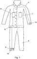
- a first intelligent item of clothing 1a for example a shirt
- a second intelligent item of clothing 1b for example trousers
- Electronics 2a are integrated in the first intelligent item of clothing 1a, which also include an electrode 19a on a cuff of the item of clothing 1a, in order, for example, to measure an electrical voltage.
- Electronics 2b are integrated in the second intelligent item of clothing 1b, for example in the form of an electrode 19b for voltage measurement.
- connection 20 does not have to be electrical either, but could also be in the form of a data connection.
- the connection 20 can establish both an electrical connection 20 and a data connection, depending on the application and functionality of the electronics 2a, 2b.
- the connection 20 can also be either wireless or wired.
- the connection 20 can also serve to transfer electrical energy from one item of clothing 1a to the other item of clothing 1b, if only one item of clothing 1a has an energy store 3, for example a lithium-ion battery, a primary battery (button cell), etc., for energy supply is provided.
- the compound 20 according to the invention is described in detail below.
- a compound 20 according to the invention is shown in Fig. 2 shown schematically and consists of a first connection part 20a and a second connection part 20b, which together form the connection 20.
- the first connecting part 20a is arranged, for example, on the first intelligent garment 1a and the second connecting part 20b is arranged on the second intelligent garment 1b.
- the two connecting parts 20a, 20b are magnetically connected to one another.
- at least one permanent magnet 4 is arranged on at least one connecting part 20a, which magnet interacts with at least one magnetic coupling part 5 on the respective other connecting part 20b.
- the magnetic coupling part 5 is either a part made of a ferromagnetic material or also a permanent magnet arranged in the correct polarity.
- the two connecting parts 20a, 20b can only be magnetically connected in a defined relative position to one another, or the correct position results automatically from the magnetic coupling.
- the at least one permanent magnet 4 and the magnetic coupling part 5 are of course arranged in such a way that they can basically interact to hold the connection 20 together magnetically.
- a signal connection part 21a, 21b is arranged in each of the two connection parts 20a, 20b in order to establish the required signal connection (s) 21, for example a data connection, an electrical connection or an energy transmission, via the connection 20.
- the two signal connection parts 21a, 21b are aligned and arranged in the correct position and position to one another at the same time in order to produce the desired signal connection.
- the signal connection 21 thus takes place automatically through the magnetic coupling in the defined position.
- the connection 20 can thus be handled very easily, since the user only has to establish the magnetic coupling and beyond doesn't have to worry about anything. Possible signal connections 21 are in Fig. 3 shown.
- a simple signal connection 21 is made by electrical contacts 23a, 23b, which are contacted by the magnetic connection of the two signal connection parts 21a, 21b, as in FIG Fig.3a shown.
- electrical contacts 23a, 23b electrical signals, for example in the form of measured values such as voltages, can be transmitted, but a data connection or energy transmission can also be implemented with them.
- a contactless energy transmission is shown as a signal connection 21.
- a first energy coupling part 6 of an inductive coupling for inductive energy transmission is arranged in the first signal connection part 21a.
- the first energy coupling part 6 comprises an inverter 7 (or oscillator) and a transmission coil 8 connected to it, which emits an electromagnetic field.
- a second energy coupling part 9 is arranged in the second signal connection part 21b.
- the second energy coupling part 9 comprises a receiving coil 10 for receiving the electromagnetic field emitted by the transmitting coil 8 and a rectifier 11 connected to it.
- the rectifier 11 can be connected to the electronics 2b of an intelligent item of clothing 1b.
- the rectifier 11 could of course also feed an energy buffer that supplies the electronics 2b.
- the inverter 7 and / or the rectifier 11 can of course also be part of the respective electronics 2a, 2b. However, it is of course fundamentally irrelevant from which item of clothing the electrical energy is transmitted.
- the magnetic connection between the two connecting parts 20a, 20b also ensures in particular that the first energy coupling part 6 (e.g. the transmitting coil 8) and the second energy coupling part 9 (e.g. the receiving coil 10) are arranged at the correct distance from one another and in the required relative position to one another, to enable contactless energy transfer.
- the first connection part 20a "snaps" onto the second connection part 20b in the correct position and position.
- contactless data transmission could also be provided as the signal connection 21, as in FIG Fig.3c shown.
- high-frequency coils 14, 16 (typically in the frequency range between 10 kHz and 1 MHz) could be provided in the first signal connection part 21a and in the second signal connection part 21b, which co-operate for data transmission.
- one of the high-frequency coils 14, 16 sends an electromagnetic field for data transmission, which is detected by the other high-frequency coil 14, 16.
- the high frequency coils 14, 16 are each connected to a communication unit 15, 17.
- the communication units 15, 17 can also be part of the respective electronics 2a, 2b.
- the data communication can take place according to any communication protocol.
- the data transmission can in particular be used to exchange data or information between the two items of clothing 1a, 1b or their electronics 2a, 2b.
- a status of the energy store 3 State of Charge SoC or State of Health SoH
- Such data can, however, also be measurement data recorded with the electronics 2a, 2b on the item of clothing 1a, 1b, for example EKG data, movement data, temperatures, electrical voltages between two points on the items of clothing 1a, 1b.
- Such data can be stored in a storage unit of an item of clothing 1a, 1b or also of the energy store 3, e.g. to be read out later.
- the magnetic connection between the two connecting parts 20a, 20b can in an advantageous embodiment of the invention according to Fig. 4 can also be used to improve contactless energy transfer or data transfer.
- the at least one permanent magnet 4 is integrated into a magnetic circuit which extends between the first connecting part 20a and the second connecting part 20b.
- two permanent magnets 4 are provided in the first connecting part 20a, for example, which are connected by a yoke 12 made of ferromagnetic material as a magnetic yoke.
- the yoke 12 serves at the same time as a core for the transmission coil 8.
- a core 13, preferably made of ferromagnetic material, is also arranged in the second connecting part 20b, on which the reception coil 10 is arranged.
- the core 13 serves as a magnetic coupling part 5 and at the same time closes the magnetic circuit.
- the at least one permanent magnet 4 in the magnetic circuit thus increases the magnetic flux flowing in the magnetic circuit, which improves the energy transfer from the transmitting coil 8 to the receiving coil 10.
- the data transmission can also be improved if the high-frequency coils 14, 16 are arranged on the yoke 12 or on the core 13.
- connection 20 is in work clothing consisting of a first item of clothing 1a and a second item of clothing 1b (as in Fig. 1 ) for people who work on live parts.
- the electronics 2a, 2b in the two items of clothing 1a, 1b can be designed and functionally interact in such a way as to generate an electrical voltage between at least two points of the work clothing, in particular between a first point on the first item of clothing 1a, for example on the wrist, and a second point on the second item of clothing 1b, for example on the ankle, as in FIG Fig. 1 indicated.
- the detected voltage can then be evaluated (by electronics 2a, 2b or external) and a desired action can be triggered (by electronics 2a, 2b or external).
- a signal connection with an electrical contact 23 as in FIG Fig.3a advantageous.
- Electronics 2a, 2b can also include a transmitting device, for example a radio transmitter, which sends an emergency stop signal to an external switching unit in the event of excessively high voltage between the measured points in order to de-energize the live parts when the voltage becomes too high exceeds the defined limit value.
- a transmission device of the energy store 3 could also be used for this purpose. In this way, possible injuries to the person wearing the work clothing due to electric shock can be limited, and fatal accidents can even be avoided entirely if this safety function is used correctly.
- a signal device on an item of clothing 1a, 1b (also as part of the electronics 2a, 2b) indicates whether the safety function is ready for operation, for example whether the connection 20 or the signal connection 21 has been established.
- the correct connection could be established, for example, with a reed contact 22 which is arranged in the connection part 20b in which the magnetic coupling part 5 is arranged.
- the magnetic field of the permanent magnet 4 can thus be detected with the reed contact 22.
- the reed contact could be designed and arranged in such a way that it closes by the magnetic field of the permanent magnet 4, whereby the correct connection could be established.
Landscapes
- Engineering & Computer Science (AREA)
- Computer Networks & Wireless Communication (AREA)
- Signal Processing (AREA)
- Textile Engineering (AREA)
- Arrangements For Transmission Of Measured Signals (AREA)
- Magnetic Treatment Devices (AREA)
- Professional, Industrial, Or Sporting Protective Garments (AREA)
Description
- Die gegenständliche Erfindung betrifft eine Anordnung aus einem ersten intelligenten Kleidungsstück mit integrierter erster Elektronik und aus einem mit dem ersten intelligenten Kleidungsstück über eine Verbindung verbundenen zweiten intelligenten Kleidungstück mit integrierter zweiter Elektronik, sowie die Verwendung der Anordnung in einer Arbeitsbekleidung für Personen, die Arbeiten an stromführenden Teilen durchführen.
- Als intelligente Kleidung werden Kleidungsstücke mit integrierter, in der Regel von außen nicht sichtbarer, Elektronik oder Elektrik bezeichnet. Mit der Elektronik können nahezu beliebige Funktionen realisiert werden, wie beispielsweise leuchtende Kleidung, Spielfunktionen (z.B. Lasertagging), Überwachung von Vitalparametern (z.B. Herzfrequenz, Blutdruck, Körpertemperatur, Atemfrequenz, Elektrokardiogramm (EKG), usw.), Sicherheitsfunktionen (z.B. um elektrische Spannungen zu detektieren, usw.), Kommunikation, Multimedia, etc. In manchen Anwendungen ist es erforderlich, zwei intelligente Kleidungsstücke miteinander zu verbinden, beispielsweise um eine mehrere Kleidungsstücke verteilte Funktionalität zu realisieren. Damit ist es notwendig, die intelligenten Kleidungsstücke elektrisch miteinander zu verbinden. Das kann entweder drahtlos und/oder drahtgebunden erfolgen.
- Die
DE 10 2014 223 983 A1 offenbart eine Anordnung von intelligenten Kleidungsstücken. - Die
US 2007/0250981 A1 beschreibt eine Vorrichtung, weelche dazu vorgesehen ist, elektrische Energie und/oder Daten durch das Material eines Kleidungsstückes zu übertragen. DieWO 2005/055390 A1 zeigt ein erstes intelligentes Kleidungsstück und ein zweites intelligentes Kleidungsstück, die über eine Knopf-Knopfloch-Verbindung miteinander verbunden sind. Sowohl Knopf als auch Knopfloch sind mit einer Spule als Signalverbindungsteil versehen, womit eine Übertragung von Energie von einem Kleidungsstück auf das andere Kleidungsstück ermöglicht wird. - Es ist daher eine Aufgabe der gegenständlichen Erfindung, eine einfache und sichere Verbindung zwischen zwei intelligente Kleidungsstücke anzugeben.
- Diese Aufgabe wird erfindungsgemäß durch die unabhängigen Ansprüche 1 und 9 gelöst. Das erste Verbindungsteil und das zweite Verbindungsteil zur Herstellung der Verbindung sind magnetisch verbunden, um einen ersten Signalverbindungsteil im ersten Verbindungsteil mit einen zweiten Signalverbindungsteil im zweiten Verbindungsteil zur Herstellung einer Signalverbindung zwischen erster Elektronik und zweiter Elektronik zueinander auszurichten und miteinander zu verbinden. Die magnetische Kopplung sorgt automatisch für die richtige Ausrichtung und Lage der beiden Signalverbindungsteile, um die benötigte Signalverbindung zu realisieren. Die Ausrichtung der beiden Signalverbindungsteile erfolgt durch die magnetische Kopplung selbsttätig, sodass die Handhabung der Verbindung ausgesprochen einfach und fehlersicher ist.
- In einer einfachen Ausgestaltung bilden das erste Signalverbindungsteil und das zweite Signalverbindungsteil einen elektrischen Kontakt aus, womit sich auf einfache Weise jegliche Signalverbindung (Energie, Datenübertragen, elektrisches Signal) herstellen lässt.
- Eine berührungslose Datenübertragung als Signalverbindung lässt sich auf einfache Weise realisieren, wenn im ersten Signalverbindungsteil und im zweiten Signalverbindungsteil jeweils eine Hochfrequenzspule angeordnet ist, die durch die magnetische Verbindung zur berührungslosen Datenübertragung zueinander ausgerichtet sind.
- Eine berührungslose Energieübertragung oder Datenübertragung als Signalverbindung lässt sich auf einfache Weise realisieren, wenn im ersten Signalverbindungsteil eine Sendespule angeordnet ist und im zweiten Signalverbindungsteil eine Empfangsspule angeordnet ist, die durch die magnetische Verbindung zur induktiven Energieübertragung zueinander ausgerichtet sind. Eine derartige induktive Energieübertragung ist einfach und sicher zu implementieren.
- Vorzugsweise ist im ersten Verbindungsteil zumindest ein Permanentmagnet angeordnet ist, der mit zumindest einem Magnetkoppelteil im zweiten Verbindungsteil zusammenwirkt, oder umgekehrt, wodurch sich die magnetische Kopplung besonders einfach realisieren lässt. Dabei ist es vorteilhaft, wenn auch der Magnetkoppelteil als Permanentmagnet ausgeführt ist, was eine starke magnetische Kopplung ermöglicht.
- Ganz besonders vorteilhaft ist der zumindest eine Permanentmagnet in einen magnetischen Kreis eingebunden, indem der Permanentmagnet mit einem Joch verbunden ist, auf dem die Sendespule, oder Empfangsspule, angeordnet ist und das Magnetkoppelteil als Kern ausgeführt ist, auf dem die Empfangsspule, oder die Sendespule, angeordnet ist. Damit kann die induktive Energieübertragung verstärkt und verbessert werden. Das gilt in analoger Weise auch für die berührungslose Datenübertragung mittels Hochfrequenzspulen.
- Die gegenständliche Erfindung wird nachfolgend unter Bezugnahme auf die
Figuren 1 bis 4 näher erläutert, die beispielhaft, schematisch und nicht einschränkend vorteilhafte Ausgestaltungen der Erfindung zeigen. Dabei zeigt -
Fig.1 zwei über eine erfindungsgemäß Verbindung miteinander verbundene intelligente Kleidungsstücke, -
Fig.2 die erfindungsgemäße magnetische Verbindung, -
Fig.3a, 3b 3c vorteilhafte Ausführungen der durch die Verbindung hergestellten Signalverbindung und -
Fig.4 die Verbesserung der berührungslosen Signalverbindung durch die Einbindung des Permanentmagneten in einen magnetische Kreis. - In
Fig.1 sind eine erste intelligentes Kleidungsstück 1a, beispielsweise ein Hemd, und ein zweites intelligentes Kleidungsstück 1b, beispielsweise eine Hose, dargestellt. Im ersten intelligenten Kleidungsstück 1a ist eine Elektronik 2a integriert, die auch eine Elektrode 19a an einem Ärmelbund des Kleidungsstücks 1a umfasst, um z.B. eine elektrische Spannung zu messen. Im zweiten intelligenten Kleidungsstück 1b ist eine Elektronik 2b integriert, beispielsweise in Form eine Elektrode 19b zur Spannungsmessung. Um zwischen der Elektrode 19a der Elektronik 2a und der Elektrode 19b der Elektronik 2b eine elektrische Spannung messen zu können, muss zwischen den beiden Elektroden 19a, 19b eine elektrische Verbindung 20 bestehen. - Eine derartige Spannungsmessung ist natürlich nur ein konkreter Anwendungsfall, in dem zwei intelligente Kleidungsstücke 1a, 1b miteinander verbunden werden müssen. Die Verbindung 20 muss auch nicht elektrisch sein, sondern könnte auch in Form eine Datenverbindung ausgeführt sein. Natürlich kann die Verbindung 20 je nach Anwendung und Funktionalität der Elektronik 2a, 2b sowohl eine elektrische Verbindung 20, als auch eine Datenverbindung herstellen. Die Verbindung 20 kann außerdem entweder drahtlos oder drahtgebunden ausgeführt sein. Die Verbindung 20 kann auch dazu dienen, elektrische Energie von einem Kleidungsstück 1a auf das andere Kleidungsstück 1b zu übertragen, wenn nur an einem Kleidungsstück 1a ein Energiespeicher 3, beispielsweise ein Li-lonen Akku, eine Primärbatterie (Knopfzelle), etc., zur Energieversorgung vorgesehen ist. Die erfindungsgemäße Verbindung 20 wird nachfolgend im Detail beschrieben.
- Eine erfindungsgemäße Verbindung 20 ist in
Fig.2 schematisch dargestellt und besteht aus einem ersten Verbindungsteil 20a und einem zweiten Verbindungsteil 20b, die zusammen die Verbindung 20 ausbilden. Der erste Verbindungsteil 20a ist beispielsweise am ersten intelligenten Kleidungsstück 1a angeordnet und der zweite Verbindungsteil 20b am zweiten intelligenten Kleidungsstück 1b. Die beiden Verbindungsteile 20a, 20b werden magnetisch miteinander verbunden. Dazu ist an zumindest einem Verbindungsteil 20a zumindest ein Permanentmagnet 4 angeordnet, der mit zumindest einem Magnetkoppelteil 5 am jeweils anderen Verbindungsteil 20b zusammenwirkt. Der Magnetkoppelteil 5 ist entweder ein Teil aus einem ferromagnetischen Material oder ebenfalls ein in der richtigen Polarität angeordneter Permanentmagnet. Damit können die beiden Verbindungsteile 20a, 20b nur in einer definierten relativen Lage zueinander magnetisch verbunden werden, bzw. ergibt sich die richtige Lage automatisch durch die magnetische Kopplung. Der zumindest eine Permanentmagnet 4 und der Magnetkoppelteil 5 sind dazu selbstverständlich so angeordnet, dass diese zum magnetischen Zusammenhalten der Verbindung 20 grundsätzlich zusammenwirken können. - Darüber hinaus ist in beiden Verbindungsteilen 20a, 20b jeweils ein Signalverbindungsteil 21a, 21b angeordnet, um über die Verbindung 20 die benötigte(n) Signalverbindung(en) 21, also beispielweise eine Datenverbindung, eine elektrische Verbindung oder eine Energieübertragung, herzustellen. Durch die magnetische Kopplung der beiden Verbindungsteile 20a, 20b werden die beiden Signalverbindungsteile 21a, 21b gleichzeitig in der richtigen Lage und Position zueinander ausgerichtet und angeordnet, um die gewünschte Signalverbindung herzustellen. Die Signalverbindung 21 erfolgt damit automatisch durch die magnetische Kopplung in der definierten Lage. Damit lässt sich die Verbindung 20 sehr einfach handhaben, da der Benutzer nur die magnetische Kopplung herstellen muss und sich darüber hinaus keinerlei Gedanken machen muss. Mögliche Signalverbindungen 21 sind in
Fig.3 dargestellt. - Eine einfache Signalverbindung 21 erfolgt durch elektrische Kontakte 23a, 23b, die durch die magnetische Verbindung der beiden Signalverbindungsteile 21a, 21b kontaktiert werden, wie in
Fig.3a dargestellt. Dabei können auch mehrere elektrische Kontakte vorgesehen sein und geschlossen werden. Mit solchen elektrischen Kontakten 23a, 23b lassen sich elektrische Signale, beispielsweise in Form von Messwerten wie Spannungen, übertragen, aber es kann damit auch eine Datenverbindung oder Energieübertragung realisiert werden. - Mit
Fig.3b ist eine berührungslose Energieübertragung als Signalverbindung 21 dargestellt. Im ersten Signalverbindungsteil 21a ist ein erster Energiekopplungsteil 6 einer induktiven Kopplung zur induktiven Energieübertragung angeordnet. Der erste Energiekopplungsteil 6 umfasst in einer einfachen Ausgestaltung einen Wechselrichter 7 (bzw. Oszillator) und eine damit verbundene Sendespule 8, die ein elektromagnetisches Feld aussendet. Im zweiten Signalverbindungsteil 21b ist ein zweiter Energiekopplungsteil 9 angeordnet. Der zweite Energiekopplungsteil 9 umfasst in einer einfachen Ausgestaltung eine Empfangsspule 10 zum Empfangen des von der Sendespule 8 ausgesendeten elektromagnetischen Feldes und einen damit verbundenen Gleichrichter 11. Der Gleichrichter 11 kann mit der Elektronik 2b eines intelligenten Kleidungsstückes 1b verbunden sein. Der Gleichrichter 11 könnte aber natürlich auch einen Energiepuffer speisen, der die Elektronik 2b versorgt. Der Wechselrichter 7 und/oder der Gleichrichter 11 kann dabei selbstverständlich auch Teil der jeweiligen Elektronik 2a, 2b sein. Es ist aber natürlich grundsätzlich unerheblich, von welchem Kleidungsstück aus die elektrische Energie übertragen wird. - Die magnetische Verbindung zwischen den beiden Verbindungsteilen 20a, 20b sorgt insbesondere auch dafür, dass der erste Energiekopplungsteil 6 (z.B. die Sendespule 8) und der zweite Energiekopplungsteil 9 (z.B. die Empfangsspule 10) im richtigen Abstand zueinander und in benötigter relativer Lage zueinander angeordnet sind, um die berührungslose Energieübertragung zu ermöglichen. Durch die magnetische Verbindung "schnappt" der erste Verbindungsteil 20a in der richtigen Lage und Position auf den zweiten Verbindungsteil 20b auf.
- In einer weiteren vorteilhaften Ausgestaltung könnte als Signalverbindung 21 auch eine berührungslose Datenübertragung vorgesehen sein, wie in
Fig.3c dargestellt. Zur berührungslosen Datenübertragung könnten im ersten Signalverbindungsteil 21a und im zweiten Signalverbindungsteil 21b jeweils Hochfrequenzspulen 14, 16 (typischerweise im Frequenzeberich zwischen 10kHz und 1MHz) vorgesehen sein, die zur Datenübertragung zusammenwirken. Dazu sendet eine der Hochfrequenzspulen 14, 16 zur Datenübertragung ein elektromagnetisches Feld, das von der jeweils anderen Hochfrequenzspule 14, 16 erfasst wird. Die Hochfrequenzspulen 14, 16 sind jeweils mit einer Kommunikationseinheit 15, 17 verbunden. Die Kommunikationseinheiten 15, 17 können dazu auch Teil der jeweiligen Elektronik 2a, 2b sein. Die Datenkommunikation kann nach einen beliebigen Kommunikationsprotokoll erfolgen. - Die Datenübertragung kann insbesondere genutzt werden, um zwischen den beiden Kleidungsstücken 1a, 1b oder deren Elektronik 2a, 2b Daten oder Information auszutauschen. Beispielsweise könnte so ein Status des Energiespeichers 3 (State of Charge SoC oder State of Health SoH) abgefragt oder übertragen werden. Solche Daten können aber auch mit der Elektronik 2a, 2b am Kleidungsstück 1a, 1b aufgenommene Messdaten sein, beispielsweise EKG-Daten, Bewegungsdaten, Temperaturen, elektrische Spannungen zwischen zwei Punkten an den Kleidungsstücken 1a, 1b. Solche Daten können in einer Speichereinheit eines Kleidungsstückes 1a, 1b oder auch des Energiespeichers 3 gespeichert werden, z.B. um später ausgelesen zu werden.
- Die magnetische Verbindung zwischen den beiden Verbindungsteilen 20a, 20b kann in einer vorteilhaften Ausgestaltung der Erfindung nach
Fig.4 auch genutzt werden, um die berührungslose Energieübertragung oder Datenübertragung zu verbessern. Dazu wird der zumindest eine Permanentmagnet 4 in einen magnetischen Kreis, der sich zwischen erstem Verbindungsteil 20a und zweitem Verbindungsteil 20b erstreckt, eingebunden. Im ersten Verbindungsteil 20a sind dazu in einer vorteilhaften Ausgestaltung beispielsweise zwei Permanentmagnete 4 vorgesehen, die durch ein Joch 12, aus ferromagnetischem Material als magnetischer Rückschluss, verbunden sind. Das Joch 12 dient gleichzeitig als Kern für die Sendespule 8. Auch im zweiten Verbindungsteil 20b ist ein Kern 13, vorzugsweise aus ferromagnetischem Material, angeordnet, auf dem die Empfangsspule 10 angeordnet ist. Der Kern 13 dient als Magnetkoppelteil 5 und schließt gleichzeitig den magnetischen Kreis. Durch die magnetische Verbindung zwischen beiden Verbindungsteilen 20a, 20b werden somit nicht nur die Sendespule 8 und die Empfangsspule 10 zueinander ausgerichtet, sondern es wird gleichzeitig der magnetische Kreis geschlossen. Der zumindest eine Permanentmagnet 4 im magnetischen Kreis erhöht damit den im magnetischen Kreis fließenden magnetischen Fluss, was die Energieübertragung von der Sendespule 8 auf die Empfangsspule 10 verbessert. In gleicher Weise kann damit auch die Datenübertragung verbessert werden, wenn die Hochfrequenzspulen 14, 16 am Joch 12 bzw. am Kern 13 angeordnet werden. - Eine besonders vorteilhafte Anwendung der erfindungsgemäßen Verbindung 20 ist in einer Arbeitsbekleidung bestehend aus einem ersten Kleidungsstück 1a und einem zweiten Kleidungsstück 1b (wie in
Fig.1 ) für Personen, die an stromführenden Teilen arbeiten. Die Elektronik 2a, 2b in den beiden Kleidungsstücken 1a, 1b kann hierbei ausgeführt sein und funktional so zusammenwirken, um eine elektrische Spannung zwischen zumindest zwei Punkten der Arbeitsbekleidung zu erfassen, insbesondere zwischen einem ersten Punkt am ersten Kleidungsstück 1a, z.B. am Handgelenk, und einen zweiten Punkt am zweiten Kleidungsstück 1b, z.B. am Fußgelenk, wie inFig.1 angedeutet. Die erfasste Spannung kann dann ausgewertet werden (durch eine Elektronik 2a, 2b oder extern) und eine gewünschte Aktion ausgelöst werden (durch eine Elektronik 2a, 2b oder extern). Für eine einfache Messung einer elektrischen Spannung über zwei Kleidungsstücke 1a, 1b und über die Verbindung 20 ist eine Signalverbindung mit einem elektrischen Kontakt 23 wie inFig.3a vorteilhaft. - Eine Elektronik 2a, 2b kann dazu auch eine Sendeeinrichtung, z.B. ein Funksender, umfassen, die im Falle einer zu hohen Spannung zwischen den gemessenen Punkten ein Notaus-Signal an eine externe Schalteinheit sendet, um die stromführenden Teile stromlos zu schalten, wenn die Spannung einen definierten Grenzwert überschreitet. Ebenso könnte dazu eine Sendeeinrichtung des Energiespeichers 3 genutzt werden. Auf diese Weise können mögliche Verletzungen der die Arbeitsbekleidung tragenden Person durch Stromschlag eingeschränkt werden, tödliche Unfälle bei richtiger Anwendung dieser Sicherheitsfunktion sogar gänzlich vermieden werden. Es kann dabei auch vorgesehen sein, durch eine Signaleinrichtung an einem Kleidungsstück 1a, 1b (ebenfalls als Teil der Elektronik 2a, 2b) anzuzeigen, ob die Sicherheitsfunktion betriebsbereit ist, beispielsweise ob die Verbindung 20, bzw. die Signalverbindung 21, hergestellt wurde.
- Die korrekte Verbindung könnte beispielsweise mit einem Reedkontakt 22 festgestellt werden, der in dem Verbindungsteil 20b angeordnet ist, in dem der Magnetkoppelteil 5 angeordnet ist. Mit dem Reedkontakt 22 kann damit das Magnetfeld des Permanentmagneten 4 erfasst werden. Wenn die magnetische Verbindung zwischen den beiden Verbindungsteilen 20a, 20b hergestellt ist, könnte der Reedkontakt so ausgeführt und angeordnet sein, dass dieser durch das Magnetfeld des Permanentmagneten 4 schließt, womit die ordnungsgemäße Verbindung festgestellt werden könnte.
Claims (10)
- Anordnung aus einem ersten intelligenten Kleidungsstück (1a) mit integrierter erster Elektronik (2a) und aus einem mit dem ersten intelligenten Kleidungsstück über eine Verbindung (20) verbundenen zweiten intelligenten Kleidungstück (1b) mit integrierter zweiter Elektronik (2b), wobei am ersten intelligenten Kleidungsstück (1a) ein erstes Verbindungsteil (20a) vorgesehen ist und an einem zweiten intelligenten Kleidungsstück (1b) ein zweites Verbindungsteil (20b) vorgesehen ist, dadurch gekennzeichnet, dass das erste Verbindungsteil (20a) und das zweite Verbindungsteil (20b) zur Herstellung der Verbindung (20) magnetisch verbunden sind, um einen ersten Signalverbindungsteil (21a) im ersten Verbindungsteil (20a) mit einen zweiten Signalverbindungsteil (21b) im zweiten Verbindungsteil (20b) zur Herstellung einer Signalverbindung (21) zwischen erster Elektronik (2a) und zweiter Elektronik (2b) zueinander auszurichten und miteinander zu verbinden.
- Anordnung nach Anspruch 1, wobei das erste Signalverbindungsteil (21a) und das zweite Signalverbindungsteil (21b) einen elektrischen Kontakt (23) ausbilden.
- Anordnung nach Anspruch 1, wobei im ersten Signalverbindungsteil (21a) und im zweiten Signalverbindungsteil (21b) jeweils eine Hochfrequenzspule (14, 16) angeordnet ist, die durch die magnetische Verbindung zur berührungslosen Datenübertragung zueinander ausgerichtet sind.
- Anordnung nach Anspruch 1, wobei im ersten Signalverbindungsteil (21a) eine Sendespule (8) angeordnet ist und im zweiten Signalverbindungsteil (21b) eine Empfangsspule (10) angeordnet ist, die durch die magnetische Verbindung zur induktiven Energieübertragung oder Datenübertragung zueinander ausgerichtet sind.
- Anordnung nach einem der Anspruch 1 bis 4, wobei im ersten Verbindungsteil (20a) zumindest ein Permanentmagnet (4) angeordnet ist, der mit zumindest einem Magnetkoppelteil (5) im zweiten Verbindungsteil (20b), oder umgekehrt, zusammenwirkt.
- Anordnung nach Anspruch 5, wobei der Magnetkoppelteil (5) als Permanentmagnet (4) ausgeführt ist.
- Anordnung nach Anspruch 3 und 5 oder 6, wobei der zumindest eine Permanentmagnet (4) in einen magnetischen Kreis eingebunden ist, indem der Permanentmagnet (4) mit einem Joch (12) verbunden ist, auf dem eine Hochfrequenzspule (14), angeordnet ist und das Magnetkoppelteil (5) als Kern (13) ausgeführt ist, auf dem die andere Hochfrequenzspule (16) angeordnet ist
- Anordnung nach Anspruch 4 und 5 oder 6, wobei der zumindest eine Permanentmagnet (4) in einen magnetischen Kreis eingebunden ist, indem der Permanentmagnet (4) mit einem Joch (12) verbunden ist, auf dem die Sendespule (8), oder Empfangsspule (10), angeordnet ist und das Magnetkoppelteil (5) als Kern (13) ausgeführt ist, auf dem die Empfangsspule (10), oder die Sendespule (8), angeordnet ist.
- Verwendung der Anordnung nach einem der Ansprüche 1 bis 8 in einer Arbeitsbekleidung für Personen, die Arbeiten an stromführenden Teilen durchführen, wobei die Arbeitsbekleidung aus dem ersten intelligenten Kleidungsstück (1a) und dem zweiten intelligenten Kleidungsstück (1b) besteht, die durch die Verbindung (20) miteinander verbunden sind und durch die Elektronik (2a, 2b) der beiden intelligenten Kleidungsstücke (1a, 1b) eine elektrische Spannung zwischen einem Punkt am ersten Kleidungsstück (1a) und einem Punkt am zweiten Kleidungsstück (1b) erfasst wird.
- Verwendung nach Anspruch 9, wobei beim Überschreiten eines vorgegebenen Grenzwertes für die Spannung durch eine Elektronik (2a, 2b) das Stromlosschalten der stromführenden Teile ausgelöst wird.
Priority Applications (1)
| Application Number | Priority Date | Filing Date | Title |
|---|---|---|---|
| PL18745599T PL3661378T3 (pl) | 2017-08-04 | 2018-07-25 | Połączenie między dwoma inteligentnymi ubraniami |
Applications Claiming Priority (2)
| Application Number | Priority Date | Filing Date | Title |
|---|---|---|---|
| AT506532017 | 2017-08-04 | ||
| PCT/EP2018/070108 WO2019025246A1 (de) | 2017-08-04 | 2018-07-25 | Verbindung zwischen zwei intelligenten kleidungsstücken |
Publications (2)
| Publication Number | Publication Date |
|---|---|
| EP3661378A1 EP3661378A1 (de) | 2020-06-10 |
| EP3661378B1 true EP3661378B1 (de) | 2021-05-19 |
Family
ID=63013047
Family Applications (1)
| Application Number | Title | Priority Date | Filing Date |
|---|---|---|---|
| EP18745599.3A Active EP3661378B1 (de) | 2017-08-04 | 2018-07-25 | Verbindung zwischen zwei intelligenten kleidungsstücken |
Country Status (5)
| Country | Link |
|---|---|
| US (1) | US11140928B2 (de) |
| EP (1) | EP3661378B1 (de) |
| ES (1) | ES2877604T3 (de) |
| PL (1) | PL3661378T3 (de) |
| WO (1) | WO2019025246A1 (de) |
Families Citing this family (2)
| Publication number | Priority date | Publication date | Assignee | Title |
|---|---|---|---|---|
| WO2019223920A1 (de) * | 2018-05-24 | 2019-11-28 | Drägerwerk AG & Co. KGaA | Personensensor und personensensorsystem |
| US20220285970A1 (en) * | 2021-03-05 | 2022-09-08 | RHiot, Inc. | Managing power between wearable devices |
Family Cites Families (19)
| Publication number | Priority date | Publication date | Assignee | Title |
|---|---|---|---|---|
| US1691472A (en) * | 1925-06-25 | 1928-11-13 | Graham | Electrically-heated garment |
| US2287915A (en) * | 1940-03-04 | 1942-06-30 | Taylor Eric Hardman | Electrically heated clothing and equipment |
| US2329766A (en) * | 1942-04-27 | 1943-09-21 | Jacobsen Walter | Electrically heated flying suit |
| FR2186923A5 (de) * | 1970-07-09 | 1974-01-11 | Spirotechnique | |
| US4404460A (en) * | 1982-03-12 | 1983-09-13 | Appleton Papers Inc. | Controllably heated clothing |
| US4876724A (en) * | 1988-04-29 | 1989-10-24 | Toshiba America, Inc. | Personal sound system |
| US6014773A (en) * | 1998-12-10 | 2000-01-18 | Banks; David L. | Monitored static electricity dissipation garment |
| US6324053B1 (en) * | 1999-11-09 | 2001-11-27 | International Business Machines Corporation | Wearable data processing system and apparel |
| DE10119283A1 (de) * | 2001-04-20 | 2002-10-24 | Philips Corp Intellectual Pty | System zur drahtlosen Übertragung elektrischer Leistung, ein Kleidungsstück, ein System von Kleidungsstücken und Verfahren zum Übertragen von Signalen und/oder elektrischer Leistung |
| US6563424B1 (en) * | 2001-05-22 | 2003-05-13 | Nokia Corporation | Smart garment system, method and apparatus involved for integrating electronic devices into garments |
| EP1692753A1 (de) | 2003-12-03 | 2006-08-23 | Koninklijke Philips Electronics N.V. | Kleidungsstück mit induktivem knopf und knopfloch |
| WO2006035385A2 (en) * | 2004-09-29 | 2006-04-06 | Koninklijke Philips Electronics, N.V. | Modular wearable circuit |
| DE102004047650B3 (de) | 2004-09-30 | 2006-04-13 | W.L. Gore & Associates Gmbh | Kleidungsstück mit induktivem Koppler und induktive Bekleidungsstückschnittstelle |
| US8188868B2 (en) | 2006-04-20 | 2012-05-29 | Nike, Inc. | Systems for activating and/or authenticating electronic devices for operation with apparel |
| DE102007035822A1 (de) | 2007-07-31 | 2009-02-05 | Robert Bosch Gmbh | Automatische Sicherheitsabschaltung von Werkzeugen oder Arbeitsgeräten |
| US8308489B2 (en) * | 2008-10-27 | 2012-11-13 | Physical Optics Corporation | Electrical garment and electrical garment and article assemblies |
| US10327481B2 (en) | 2013-12-31 | 2019-06-25 | Suunto Oy | Arrangement and method for configuring equipment |
| DE102014223983A1 (de) * | 2014-11-25 | 2016-05-25 | Robert Bosch Gmbh | Sicherheitskleidungsstück |
| US9859747B2 (en) * | 2015-09-08 | 2018-01-02 | Futureplay, Inc. | Garment device and system having wireless charging function, and charging method using the same |
-
2018
- 2018-07-25 ES ES18745599T patent/ES2877604T3/es active Active
- 2018-07-25 US US16/635,478 patent/US11140928B2/en active Active
- 2018-07-25 EP EP18745599.3A patent/EP3661378B1/de active Active
- 2018-07-25 WO PCT/EP2018/070108 patent/WO2019025246A1/de not_active Ceased
- 2018-07-25 PL PL18745599T patent/PL3661378T3/pl unknown
Also Published As
| Publication number | Publication date |
|---|---|
| WO2019025246A1 (de) | 2019-02-07 |
| EP3661378A1 (de) | 2020-06-10 |
| US11140928B2 (en) | 2021-10-12 |
| ES2877604T3 (es) | 2021-11-17 |
| US20200367576A1 (en) | 2020-11-26 |
| PL3661378T3 (pl) | 2021-11-08 |
Similar Documents
| Publication | Publication Date | Title |
|---|---|---|
| DE602004011671T2 (de) | Elektrischer verbinder | |
| EP0499939B1 (de) | Ladesystem für implantierbare Hörhilfen und Tinnitus-Maskierer | |
| EP2806944B1 (de) | Tragevorrichtung zum tragen einer sendespule am körper eines patienten | |
| EP1793693B1 (de) | Kleidungsstück mit induktivem koppler, induktive bekleidungsstückschnittstelle und verwendung der schnittstelle für kleidungsstücke | |
| DE102013227202B4 (de) | Druckknopf zur Integration in ein Kleidungsstück | |
| EP0744061A1 (de) | Kombinierte chipkarte | |
| DE112017000837T5 (de) | System und verfahren zur steuerung drahtloser leistungsübertragung | |
| EP3661378B1 (de) | Verbindung zwischen zwei intelligenten kleidungsstücken | |
| DE112013002708T5 (de) | Netzwerk elektronischer Vorrichtungen, die auf einem flexiblen Träger angebracht sind, und Kommunikationsverfahren | |
| DE102012200912B4 (de) | Tragevorrichtung zum Tragen einer Sendespule | |
| DE212015000230U1 (de) | Induktive Kopplungsbaugruppe für ein elektronisches Gerät | |
| DE102014008684A1 (de) | Intelligente elektrode | |
| DE102010028993B4 (de) | Antennenanordnung und Transponderlesegerät | |
| DE112019003325T5 (de) | In-vivo implantierbare medizinische vorrichtung | |
| EP1693863B1 (de) | Bekleidungsstück mit induktiver Energieübertragung | |
| DE102014201931A1 (de) | Steuervorrichtung, medizinisches Steuersystem und Verfahren zur Übertragung eines Befehls | |
| EP4036591A1 (de) | Batteriezelle mit überwachungseinrichtung | |
| DE3936547A1 (de) | Anordnung zur telemetrischen kommunikation zwischen zwei geraeten mittels eines magnetischen nahfeldes | |
| WO2019025247A1 (de) | Intelligentes kleidungsstück mit energiespeicher | |
| DE102016117762A1 (de) | System zur Muskelstimulation | |
| DE202016105258U1 (de) | System zur Muskelstimulation | |
| WO2019243388A1 (de) | Mobiler elektroarbeitsplatz mit schutzausrüstung gegen stromschlag | |
| AT521371B1 (de) | Elektrische Anlage mit Notsignaleingang zum Empfangen eines über Funk gesendeten Notsignals | |
| DE102012005371A1 (de) | Steuervorrichtung eines Bedienelements in einem Kraftfahrzeug | |
| DE102023208859A1 (de) | Induktionsspulenanordnungen für elektronische vorrichtungen und zubehör |
Legal Events
| Date | Code | Title | Description |
|---|---|---|---|
| STAA | Information on the status of an ep patent application or granted ep patent |
Free format text: STATUS: UNKNOWN |
|
| STAA | Information on the status of an ep patent application or granted ep patent |
Free format text: STATUS: THE INTERNATIONAL PUBLICATION HAS BEEN MADE |
|
| PUAI | Public reference made under article 153(3) epc to a published international application that has entered the european phase |
Free format text: ORIGINAL CODE: 0009012 |
|
| STAA | Information on the status of an ep patent application or granted ep patent |
Free format text: STATUS: REQUEST FOR EXAMINATION WAS MADE |
|
| 17P | Request for examination filed |
Effective date: 20200114 |
|
| AK | Designated contracting states |
Kind code of ref document: A1 Designated state(s): AL AT BE BG CH CY CZ DE DK EE ES FI FR GB GR HR HU IE IS IT LI LT LU LV MC MK MT NL NO PL PT RO RS SE SI SK SM TR |
|
| AX | Request for extension of the european patent |
Extension state: BA ME |
|
| DAV | Request for validation of the european patent (deleted) | ||
| DAX | Request for extension of the european patent (deleted) | ||
| GRAP | Despatch of communication of intention to grant a patent |
Free format text: ORIGINAL CODE: EPIDOSNIGR1 |
|
| STAA | Information on the status of an ep patent application or granted ep patent |
Free format text: STATUS: GRANT OF PATENT IS INTENDED |
|
| INTG | Intention to grant announced |
Effective date: 20210305 |
|
| GRAS | Grant fee paid |
Free format text: ORIGINAL CODE: EPIDOSNIGR3 |
|
| GRAA | (expected) grant |
Free format text: ORIGINAL CODE: 0009210 |
|
| STAA | Information on the status of an ep patent application or granted ep patent |
Free format text: STATUS: THE PATENT HAS BEEN GRANTED |
|
| AK | Designated contracting states |
Kind code of ref document: B1 Designated state(s): AL AT BE BG CH CY CZ DE DK EE ES FI FR GB GR HR HU IE IS IT LI LT LU LV MC MK MT NL NO PL PT RO RS SE SI SK SM TR |
|
| RAP3 | Party data changed (applicant data changed or rights of an application transferred) |
Owner name: ADAPTIVE REGELSYSTEME GESELLSCHAFT MBH |
|
| REG | Reference to a national code |
Ref country code: GB Ref legal event code: FG4D Free format text: NOT ENGLISH |
|
| REG | Reference to a national code |
Ref country code: CH Ref legal event code: EP |
|
| REG | Reference to a national code |
Ref country code: DE Ref legal event code: R096 Ref document number: 502018005348 Country of ref document: DE |
|
| REG | Reference to a national code |
Ref country code: AT Ref legal event code: REF Ref document number: 1393143 Country of ref document: AT Kind code of ref document: T Effective date: 20210615 |
|
| REG | Reference to a national code |
Ref country code: IE Ref legal event code: FG4D Free format text: LANGUAGE OF EP DOCUMENT: GERMAN |
|
| REG | Reference to a national code |
Ref country code: LT Ref legal event code: MG9D |
|
| REG | Reference to a national code |
Ref country code: NL Ref legal event code: MP Effective date: 20210519 |
|
| PG25 | Lapsed in a contracting state [announced via postgrant information from national office to epo] |
Ref country code: LT Free format text: LAPSE BECAUSE OF FAILURE TO SUBMIT A TRANSLATION OF THE DESCRIPTION OR TO PAY THE FEE WITHIN THE PRESCRIBED TIME-LIMIT Effective date: 20210519 Ref country code: HR Free format text: LAPSE BECAUSE OF FAILURE TO SUBMIT A TRANSLATION OF THE DESCRIPTION OR TO PAY THE FEE WITHIN THE PRESCRIBED TIME-LIMIT Effective date: 20210519 Ref country code: FI Free format text: LAPSE BECAUSE OF FAILURE TO SUBMIT A TRANSLATION OF THE DESCRIPTION OR TO PAY THE FEE WITHIN THE PRESCRIBED TIME-LIMIT Effective date: 20210519 Ref country code: BG Free format text: LAPSE BECAUSE OF FAILURE TO SUBMIT A TRANSLATION OF THE DESCRIPTION OR TO PAY THE FEE WITHIN THE PRESCRIBED TIME-LIMIT Effective date: 20210819 |
|
| REG | Reference to a national code |
Ref country code: ES Ref legal event code: FG2A Ref document number: 2877604 Country of ref document: ES Kind code of ref document: T3 Effective date: 20211117 |
|
| PG25 | Lapsed in a contracting state [announced via postgrant information from national office to epo] |
Ref country code: SE Free format text: LAPSE BECAUSE OF FAILURE TO SUBMIT A TRANSLATION OF THE DESCRIPTION OR TO PAY THE FEE WITHIN THE PRESCRIBED TIME-LIMIT Effective date: 20210519 Ref country code: RS Free format text: LAPSE BECAUSE OF FAILURE TO SUBMIT A TRANSLATION OF THE DESCRIPTION OR TO PAY THE FEE WITHIN THE PRESCRIBED TIME-LIMIT Effective date: 20210519 Ref country code: PT Free format text: LAPSE BECAUSE OF FAILURE TO SUBMIT A TRANSLATION OF THE DESCRIPTION OR TO PAY THE FEE WITHIN THE PRESCRIBED TIME-LIMIT Effective date: 20210920 Ref country code: LV Free format text: LAPSE BECAUSE OF FAILURE TO SUBMIT A TRANSLATION OF THE DESCRIPTION OR TO PAY THE FEE WITHIN THE PRESCRIBED TIME-LIMIT Effective date: 20210519 Ref country code: NO Free format text: LAPSE BECAUSE OF FAILURE TO SUBMIT A TRANSLATION OF THE DESCRIPTION OR TO PAY THE FEE WITHIN THE PRESCRIBED TIME-LIMIT Effective date: 20210819 Ref country code: IS Free format text: LAPSE BECAUSE OF FAILURE TO SUBMIT A TRANSLATION OF THE DESCRIPTION OR TO PAY THE FEE WITHIN THE PRESCRIBED TIME-LIMIT Effective date: 20210919 Ref country code: GR Free format text: LAPSE BECAUSE OF FAILURE TO SUBMIT A TRANSLATION OF THE DESCRIPTION OR TO PAY THE FEE WITHIN THE PRESCRIBED TIME-LIMIT Effective date: 20210820 |
|
| PG25 | Lapsed in a contracting state [announced via postgrant information from national office to epo] |
Ref country code: NL Free format text: LAPSE BECAUSE OF FAILURE TO SUBMIT A TRANSLATION OF THE DESCRIPTION OR TO PAY THE FEE WITHIN THE PRESCRIBED TIME-LIMIT Effective date: 20210519 |
|
| PG25 | Lapsed in a contracting state [announced via postgrant information from national office to epo] |
Ref country code: EE Free format text: LAPSE BECAUSE OF FAILURE TO SUBMIT A TRANSLATION OF THE DESCRIPTION OR TO PAY THE FEE WITHIN THE PRESCRIBED TIME-LIMIT Effective date: 20210519 Ref country code: SK Free format text: LAPSE BECAUSE OF FAILURE TO SUBMIT A TRANSLATION OF THE DESCRIPTION OR TO PAY THE FEE WITHIN THE PRESCRIBED TIME-LIMIT Effective date: 20210519 Ref country code: RO Free format text: LAPSE BECAUSE OF FAILURE TO SUBMIT A TRANSLATION OF THE DESCRIPTION OR TO PAY THE FEE WITHIN THE PRESCRIBED TIME-LIMIT Effective date: 20210519 Ref country code: SM Free format text: LAPSE BECAUSE OF FAILURE TO SUBMIT A TRANSLATION OF THE DESCRIPTION OR TO PAY THE FEE WITHIN THE PRESCRIBED TIME-LIMIT Effective date: 20210519 Ref country code: CZ Free format text: LAPSE BECAUSE OF FAILURE TO SUBMIT A TRANSLATION OF THE DESCRIPTION OR TO PAY THE FEE WITHIN THE PRESCRIBED TIME-LIMIT Effective date: 20210519 Ref country code: DK Free format text: LAPSE BECAUSE OF FAILURE TO SUBMIT A TRANSLATION OF THE DESCRIPTION OR TO PAY THE FEE WITHIN THE PRESCRIBED TIME-LIMIT Effective date: 20210519 |
|
| REG | Reference to a national code |
Ref country code: DE Ref legal event code: R097 Ref document number: 502018005348 Country of ref document: DE |
|
| REG | Reference to a national code |
Ref country code: CH Ref legal event code: PL |
|
| PLBE | No opposition filed within time limit |
Free format text: ORIGINAL CODE: 0009261 |
|
| STAA | Information on the status of an ep patent application or granted ep patent |
Free format text: STATUS: NO OPPOSITION FILED WITHIN TIME LIMIT |
|
| PG25 | Lapsed in a contracting state [announced via postgrant information from national office to epo] |
Ref country code: MC Free format text: LAPSE BECAUSE OF FAILURE TO SUBMIT A TRANSLATION OF THE DESCRIPTION OR TO PAY THE FEE WITHIN THE PRESCRIBED TIME-LIMIT Effective date: 20210519 |
|
| REG | Reference to a national code |
Ref country code: BE Ref legal event code: MM Effective date: 20210731 |
|
| 26N | No opposition filed |
Effective date: 20220222 |
|
| PG25 | Lapsed in a contracting state [announced via postgrant information from national office to epo] |
Ref country code: LI Free format text: LAPSE BECAUSE OF NON-PAYMENT OF DUE FEES Effective date: 20210731 Ref country code: CH Free format text: LAPSE BECAUSE OF NON-PAYMENT OF DUE FEES Effective date: 20210731 |
|
| PG25 | Lapsed in a contracting state [announced via postgrant information from national office to epo] |
Ref country code: IS Free format text: LAPSE BECAUSE OF FAILURE TO SUBMIT A TRANSLATION OF THE DESCRIPTION OR TO PAY THE FEE WITHIN THE PRESCRIBED TIME-LIMIT Effective date: 20210919 Ref country code: LU Free format text: LAPSE BECAUSE OF NON-PAYMENT OF DUE FEES Effective date: 20210725 Ref country code: AL Free format text: LAPSE BECAUSE OF FAILURE TO SUBMIT A TRANSLATION OF THE DESCRIPTION OR TO PAY THE FEE WITHIN THE PRESCRIBED TIME-LIMIT Effective date: 20210519 |
|
| PG25 | Lapsed in a contracting state [announced via postgrant information from national office to epo] |
Ref country code: IE Free format text: LAPSE BECAUSE OF NON-PAYMENT OF DUE FEES Effective date: 20210725 Ref country code: BE Free format text: LAPSE BECAUSE OF NON-PAYMENT OF DUE FEES Effective date: 20210731 |
|
| PG25 | Lapsed in a contracting state [announced via postgrant information from national office to epo] |
Ref country code: CY Free format text: LAPSE BECAUSE OF FAILURE TO SUBMIT A TRANSLATION OF THE DESCRIPTION OR TO PAY THE FEE WITHIN THE PRESCRIBED TIME-LIMIT Effective date: 20210519 |
|
| P01 | Opt-out of the competence of the unified patent court (upc) registered |
Effective date: 20230615 |
|
| PG25 | Lapsed in a contracting state [announced via postgrant information from national office to epo] |
Ref country code: HU Free format text: LAPSE BECAUSE OF FAILURE TO SUBMIT A TRANSLATION OF THE DESCRIPTION OR TO PAY THE FEE WITHIN THE PRESCRIBED TIME-LIMIT; INVALID AB INITIO Effective date: 20180725 |
|
| PG25 | Lapsed in a contracting state [announced via postgrant information from national office to epo] |
Ref country code: MK Free format text: LAPSE BECAUSE OF FAILURE TO SUBMIT A TRANSLATION OF THE DESCRIPTION OR TO PAY THE FEE WITHIN THE PRESCRIBED TIME-LIMIT Effective date: 20210519 |
|
| REG | Reference to a national code |
Ref country code: AT Ref legal event code: MM01 Ref document number: 1393143 Country of ref document: AT Kind code of ref document: T Effective date: 20230725 |
|
| PG25 | Lapsed in a contracting state [announced via postgrant information from national office to epo] |
Ref country code: MT Free format text: LAPSE BECAUSE OF FAILURE TO SUBMIT A TRANSLATION OF THE DESCRIPTION OR TO PAY THE FEE WITHIN THE PRESCRIBED TIME-LIMIT Effective date: 20210519 |
|
| PG25 | Lapsed in a contracting state [announced via postgrant information from national office to epo] |
Ref country code: AT Free format text: LAPSE BECAUSE OF NON-PAYMENT OF DUE FEES Effective date: 20230725 |
|
| PG25 | Lapsed in a contracting state [announced via postgrant information from national office to epo] |
Ref country code: AT Free format text: LAPSE BECAUSE OF NON-PAYMENT OF DUE FEES Effective date: 20230725 |
|
| PGFP | Annual fee paid to national office [announced via postgrant information from national office to epo] |
Ref country code: PL Payment date: 20250630 Year of fee payment: 8 |
|
| PGFP | Annual fee paid to national office [announced via postgrant information from national office to epo] |
Ref country code: ES Payment date: 20250808 Year of fee payment: 8 |
|
| PGFP | Annual fee paid to national office [announced via postgrant information from national office to epo] |
Ref country code: DE Payment date: 20250724 Year of fee payment: 8 |
|
| PGFP | Annual fee paid to national office [announced via postgrant information from national office to epo] |
Ref country code: IT Payment date: 20250715 Year of fee payment: 8 |
|
| PGFP | Annual fee paid to national office [announced via postgrant information from national office to epo] |
Ref country code: GB Payment date: 20250725 Year of fee payment: 8 |
|
| PGFP | Annual fee paid to national office [announced via postgrant information from national office to epo] |
Ref country code: FR Payment date: 20250728 Year of fee payment: 8 |
|
| PG25 | Lapsed in a contracting state [announced via postgrant information from national office to epo] |
Ref country code: TR Free format text: LAPSE BECAUSE OF FAILURE TO SUBMIT A TRANSLATION OF THE DESCRIPTION OR TO PAY THE FEE WITHIN THE PRESCRIBED TIME-LIMIT Effective date: 20210519 |
|
| PGFP | Annual fee paid to national office [announced via postgrant information from national office to epo] |
Ref country code: AT Payment date: 20260410 Year of fee payment: 5 |