EP3661449B1 - Couvercle de conception modulaire pour conteneur de stérilisation et cache filtrant d'un tel couvercle - Google Patents
Couvercle de conception modulaire pour conteneur de stérilisation et cache filtrant d'un tel couvercle Download PDFInfo
- Publication number
- EP3661449B1 EP3661449B1 EP18762009.1A EP18762009A EP3661449B1 EP 3661449 B1 EP3661449 B1 EP 3661449B1 EP 18762009 A EP18762009 A EP 18762009A EP 3661449 B1 EP3661449 B1 EP 3661449B1
- Authority
- EP
- European Patent Office
- Prior art keywords
- lid
- filter covering
- filter
- clip
- lid component
- Prior art date
- Legal status (The legal status is an assumption and is not a legal conclusion. Google has not performed a legal analysis and makes no representation as to the accuracy of the status listed.)
- Active
Links
Images
Classifications
-
- A—HUMAN NECESSITIES
- A61—MEDICAL OR VETERINARY SCIENCE; HYGIENE
- A61B—DIAGNOSIS; SURGERY; IDENTIFICATION
- A61B50/00—Containers, covers, furniture or holders specially adapted for surgical or diagnostic appliances or instruments, e.g. sterile covers
- A61B50/30—Containers specially adapted for packaging, protecting, dispensing, collecting or disposing of surgical or diagnostic appliances or instruments
-
- A—HUMAN NECESSITIES
- A61—MEDICAL OR VETERINARY SCIENCE; HYGIENE
- A61L—METHODS OR APPARATUS FOR STERILISING MATERIALS OR OBJECTS IN GENERAL; DISINFECTION, STERILISATION OR DEODORISATION OF AIR; CHEMICAL ASPECTS OF BANDAGES, DRESSINGS, ABSORBENT PADS OR SURGICAL ARTICLES; MATERIALS FOR BANDAGES, DRESSINGS, ABSORBENT PADS OR SURGICAL ARTICLES
- A61L2/00—Disinfection or sterilisation of materials or objects, in general; Accessories therefor
- A61L2/02—Disinfection or sterilisation of materials or objects, in general; Accessories therefor using physical processes
- A61L2/022—Filtration
-
- A—HUMAN NECESSITIES
- A61—MEDICAL OR VETERINARY SCIENCE; HYGIENE
- A61L—METHODS OR APPARATUS FOR STERILISING MATERIALS OR OBJECTS IN GENERAL; DISINFECTION, STERILISATION OR DEODORISATION OF AIR; CHEMICAL ASPECTS OF BANDAGES, DRESSINGS, ABSORBENT PADS OR SURGICAL ARTICLES; MATERIALS FOR BANDAGES, DRESSINGS, ABSORBENT PADS OR SURGICAL ARTICLES
- A61L2/00—Disinfection or sterilisation of materials or objects, in general; Accessories therefor
- A61L2/26—Accessories
-
- A—HUMAN NECESSITIES
- A61—MEDICAL OR VETERINARY SCIENCE; HYGIENE
- A61B—DIAGNOSIS; SURGERY; IDENTIFICATION
- A61B17/00—Surgical instruments, devices or methods
- A61B2017/00831—Material properties
- A61B2017/00902—Material properties transparent or translucent
- A61B2017/00907—Material properties transparent or translucent for light
-
- A—HUMAN NECESSITIES
- A61—MEDICAL OR VETERINARY SCIENCE; HYGIENE
- A61B—DIAGNOSIS; SURGERY; IDENTIFICATION
- A61B50/00—Containers, covers, furniture or holders specially adapted for surgical or diagnostic appliances or instruments, e.g. sterile covers
- A61B2050/005—Containers, covers, furniture or holders specially adapted for surgical or diagnostic appliances or instruments, e.g. sterile covers with a lid or cover
- A61B2050/0067—Types of closures or fasteners
- A61B2050/007—Locking clamps
-
- A—HUMAN NECESSITIES
- A61—MEDICAL OR VETERINARY SCIENCE; HYGIENE
- A61B—DIAGNOSIS; SURGERY; IDENTIFICATION
- A61B50/00—Containers, covers, furniture or holders specially adapted for surgical or diagnostic appliances or instruments, e.g. sterile covers
- A61B2050/005—Containers, covers, furniture or holders specially adapted for surgical or diagnostic appliances or instruments, e.g. sterile covers with a lid or cover
- A61B2050/0067—Types of closures or fasteners
- A61B2050/0083—Snap connection
-
- A—HUMAN NECESSITIES
- A61—MEDICAL OR VETERINARY SCIENCE; HYGIENE
- A61L—METHODS OR APPARATUS FOR STERILISING MATERIALS OR OBJECTS IN GENERAL; DISINFECTION, STERILISATION OR DEODORISATION OF AIR; CHEMICAL ASPECTS OF BANDAGES, DRESSINGS, ABSORBENT PADS OR SURGICAL ARTICLES; MATERIALS FOR BANDAGES, DRESSINGS, ABSORBENT PADS OR SURGICAL ARTICLES
- A61L2103/00—Materials or objects being the target of disinfection or sterilisation
- A61L2103/15—Laboratory, medical or dentistry appliances, e.g. catheters or sharps
-
- A—HUMAN NECESSITIES
- A61—MEDICAL OR VETERINARY SCIENCE; HYGIENE
- A61L—METHODS OR APPARATUS FOR STERILISING MATERIALS OR OBJECTS IN GENERAL; DISINFECTION, STERILISATION OR DEODORISATION OF AIR; CHEMICAL ASPECTS OF BANDAGES, DRESSINGS, ABSORBENT PADS OR SURGICAL ARTICLES; MATERIALS FOR BANDAGES, DRESSINGS, ABSORBENT PADS OR SURGICAL ARTICLES
- A61L2202/00—Aspects relating to methods or apparatus for disinfecting or sterilising materials or objects
- A61L2202/10—Apparatus features
- A61L2202/12—Apparatus for isolating biocidal substances from the environment
- A61L2202/121—Sealings, e.g. doors, covers, valves, sluices
-
- A—HUMAN NECESSITIES
- A61—MEDICAL OR VETERINARY SCIENCE; HYGIENE
- A61L—METHODS OR APPARATUS FOR STERILISING MATERIALS OR OBJECTS IN GENERAL; DISINFECTION, STERILISATION OR DEODORISATION OF AIR; CHEMICAL ASPECTS OF BANDAGES, DRESSINGS, ABSORBENT PADS OR SURGICAL ARTICLES; MATERIALS FOR BANDAGES, DRESSINGS, ABSORBENT PADS OR SURGICAL ARTICLES
- A61L2202/00—Aspects relating to methods or apparatus for disinfecting or sterilising materials or objects
- A61L2202/10—Apparatus features
- A61L2202/12—Apparatus for isolating biocidal substances from the environment
- A61L2202/123—Connecting means
-
- A—HUMAN NECESSITIES
- A61—MEDICAL OR VETERINARY SCIENCE; HYGIENE
- A61L—METHODS OR APPARATUS FOR STERILISING MATERIALS OR OBJECTS IN GENERAL; DISINFECTION, STERILISATION OR DEODORISATION OF AIR; CHEMICAL ASPECTS OF BANDAGES, DRESSINGS, ABSORBENT PADS OR SURGICAL ARTICLES; MATERIALS FOR BANDAGES, DRESSINGS, ABSORBENT PADS OR SURGICAL ARTICLES
- A61L2202/00—Aspects relating to methods or apparatus for disinfecting or sterilising materials or objects
- A61L2202/10—Apparatus features
- A61L2202/18—Aseptic storing means
- A61L2202/182—Rigid packaging means
Definitions
- the invention relates to a modular lid for a sterile container, a sterile container with such a lid, and a filter cover for such a lid.
- Sterile containers are generally known from the state of the art and are used in medicine in particular to sterilize surgical instruments, implants and the like and to store or transport them for a short time after sterilization.
- Objects to be sterilized are generally first placed in the sterile container or in a tub-like first container part of the sterile container.
- a lid-like second container part or a lid is then placed on or on the tub-like first container part and the two container parts are closed together.
- the closed sterile container is fed to a sterilizer.
- the objects to be sterilized located in the interior of the container are sterilized using any sterilization process (e.g. hot air sterilization, steam sterilization, etc.).
- filter devices/filters which prevent germs, bacteria or similar from penetrating the sterile container and are intended to enable sterile media exchange during sterilization.
- the filter devices can often be mounted and dismantled from the inside of the sterile container and are attached to an inside of the lid on a gas exchange section, in particular a perforated one. of the lid.
- a gas exchange section in particular a perforated one. of the lid.
- the gas exchange section is covered by an outer cover/filter cover, which serves to protect the filter device from mechanical influences, for example during transport or storage.
- the filter covers are generally already mounted or attached to the lid components of the sterile container lid at the factory.
- These known integral solutions for a sterile container lid are often difficult for a user to handle, especially since the filter cover cannot simply be removed from the lid component and the filter cannot be viewed by a user from the outside.
- Filter devices mounted from the inside are therefore often only checked for possible damage after the sterilized objects have been removed by a sterile user. If it is then determined that the filter device is damaged or not present at all, the removed objects must be sterilized again, a possibly contaminated instrument table on which the removed objects were placed in the meantime must be cleaned and the sterile user may have to change clothes.
- a sterile container or a sterile container lid is to be provided which is easier for a user to handle and which simplifies checking a filter device/a filter without first opening the sterile container.
- the invention initially relates to a modularly constructed lid for a sterile container or a sterile container with: a lid component which has at least one, in particular perforated, gas exchange section, on which at least one filter device can be arranged/arranged on an inner side of the lid, and at least one, preferably (at least partially) transparent, filter cover which (completely) covers the at least one gas exchange section on an outer side of the lid or with which the at least one gas exchange section can be (completely) covered, wherein the lid component has at least one, in particular standardized, clip receiving section and the filter cover has at least one, in particular standardized, clip section (or vice versa), via which the filter cover and the lid component can be fastened to one another in a form-fitting manner, in particular by clipping on, and can be assembled and disassembled without tools.
- a lid component which has at least one, in particular perforated, gas exchange section, on which at least one filter device can be arranged/arranged on an inner side of the lid, and at least one,
- a central aspect of the present invention is the modular construction of the lid.
- the lid component and the filter cover represent two separate components which can be made available to a user both in an assembled state and in a disassembled/separate state.
- the lid component is preferably a component which is adapted to completely cover and close a tub-like container part of a sterile container.
- the filter cover/outer cover serves to protect the filter device, which can be designed, for example, as a filter, filter element, combination of filter holder and filter element, etc., from mechanical influences (e.g. pointed/sharp-edged objects which can pierce or cut into the filter) and prevents/reduces the penetration of liquids into the sterile container.
- the filter device can preferably be arranged on an inner side of the lid/sterile container on a gas exchange section of the lid component and covers this gas exchange section, which further preferably has a plurality of perforations/holes, so that gas exchange between the inside of a sterile container/lid and the outside of a sterile container/lid can take place (exclusively) via the filter device.
- the gas exchange section is preferably completely covered (over its entire surface) by the filter cover.
- the cover component further preferably has at least one, preferably two, standardized receptacle(s)/at least one, preferably two, standardized clip receiving section(s), which is/are suitable for positively receiving filter covers with different properties, each of which has at least one, preferably two, standardized engagement section(s)/at least one, preferably two, standardized clip section(s).
- a user can be provided with different filter covers which differ in material or cost, in their mechanical properties, sealing properties or in their preferred intended use (for example, different sterilization processes).
- the different filter covers are optionally interchangeable, so that a filter cover whose properties are adapted to the respective area of application can be used.
- the filter cover and the lid component are form-fitting, can be attached and can be assembled and disassembled without the use of tools makes them easy to handle and can be retrofitted with further developed filter covers. Furthermore, after sterilization, the filter cover can be easily removed from the lid component by hand and the condition of the filter device can be checked by a user without having to open the sterile container. For example, the user can see whether the filter device is inserted, whether it is possibly damaged, or, if a process indicator is attached to the filter device, check whether the filter device has been subjected to a sterilization-like process.
- the filter cover is therefore preferably disassembled and reassembled after each sterilization process, which also results in improved cleaning of both the lid component and the filter cover.
- the filter cover of the modularly constructed lid can preferably be made in one piece (at least partially) from a transparent plastic, preferably using an injection molding process. This has the additional advantage that a user can see the filter device even when the filter cover is mounted on the lid component. Furthermore, the filter cover is thus realized in a cost-effective manner and is easy to handle and manufacture.
- a generic lid component of a sterile container (as well as the present sterile container according to the invention), as already described above, has a substantially flat/level top/outside of the lid (hereinafter also referred to as the lid component main plane), which is surrounded by a frame that is usually/optionally formed on it (as a single piece) by flanging/deep drawing, which can be dimensioned such that when the lid component is placed on the trough-like container part, it grips around the outside edge of the latter.
- the gas exchange section that forms on the outside of the lid defines a plane that is raised/offset in height from the lid component main plane.
- the lid component main plane and the plane defined/spanned by the gas exchange section are connected to one another via a frame-shaped base/transition section that surrounds the gas exchange section and is preferably formed as a single piece on the lid component main plane.
- a recess or grip-like depression/trough (with respect to the main plane of the lid component) is now provided on the preferably standardized clip receiving section of the lid component, on which the lid component, in particular via recess/trough side surfaces or flanks formed thereon, is connected from the main plane of the lid component to a recess base area offset downwards by a first height relative to the main plane of the lid component (towards an inner side of the lid/sterile container inner side) (possibly running parallel to the main plane of the lid component) and via the transition section, which is undercut/recessed or S-shaped at least in this area, from the recess base area to the Lid component main plane (if necessary also parallel), in particular offset by a second height relative to the lid component main plane upwards (towards an outside of the lid/sterile container outside), gas exchange section.
- a handle or recess is formed on the main plane of the lid component on opposite sides of the gas exchange section, the edge of the recess facing the gas exchange section forming an undercut (S-shaped cross-section) into which the clip sections of the filter cover (spring-elastic) that are preferably also opposite one another engage in a locking manner when it is placed on the gas exchange section or the transition section/base (for example in the manner of a well-known food storage container with a lid). If the filter cover is to be removed again, all that is needed is to grasp the lower edge area of the filter cover (facing the main plane of the lid component) with your fingertips in the area of the handles/recesses and pull the filter cover elastically over the respective undercut.
- the (standardized) clip section of the filter cover of the modularly constructed lid is designed as a C-shaped/clamp-like side section/end section/bar of the filter cover and a gripping section protruding laterally outwards is arranged on the C-shaped side section, which can be manually actuated during assembly and disassembly of the filter cover on the lid component due to the gripping shell/recess formed in this area, as already described above.
- the clip section of the filter cover of the modularly constructed cover is preferably formed on a side/end/edge section of the filter cover as a clamp-like/C-shaped section bent away from a top of the filter cover (hereinafter also referred to as the filter cover main plane).
- the filter cover is laterally limited at least in sections on at least one side/edge/end by the clip section.
- the gripping portion preferably extends outwardly away from the clip portion parallel to the filter cover main plane.
- the clamp-like side section/end section of the filter cover which forms the clip section, engages or is clipped into the undercut transition section of the clip receiving section of the cover component, as has also already been indicated above.
- Clipping the filter cover into/onto the cover component provides a suitable mechanical connection, particularly when the clip section and the gripping section of the filter cover are arranged/provided on one side/edge/end of the filter cover, with which the filter cover and the cover component can be positively secured to one another and can be assembled and disassembled without tools.
- the clip portion is preferably designed as a clamp-like side portion/end portion of the filter cover and the clip receiving portion has an S-shaped (undercut) portion, wherein in the assembled state of the filter cover on the cover component, the clamp-like side portion of the filter cover engages/is clipped into the undercut portion of the clip receiving portion.
- the filter cover of the modularly constructed lid has two clip sections which are arranged on opposite, preferably parallel, sides and/or ends of the filter cover, and the lid component has two clip receiving sections which are arranged on opposite, preferably parallel, sides and/or ends of the gas exchange section, and in the assembled state of the filter cover on the lid component, the two clip sections engage/are clipped into the two clip receiving sections.
- the first clip section When mounting the filter cover on the cover component, the first clip section is preferably first inserted into the first clip receiving section. The second clip section is then pressed into the second clip receiving section by manually operating the gripping section, with the filter cover being reversibly and elastically bent open. When dismantling the filter cover from the cover component, the filter cover is pressed downwards at a central section thereof and is pulled on one of the two gripping sections, causing the filter cover to be reversibly and elastically bent open and removed from the cover component.
- the filter cover is made of an amorphous thermoplastic and is transparent, allowing a visual inspection of the filter device from the outside of the cover without first dismantling the filter cover from the cover component.
- the filter cover is transparent, a user can check its condition without having to remove the filter cover from the cover component. For example, the user can see whether the filter device is inserted, whether it is possibly damaged, or, if a process indicator is attached to the filter device, check whether the filter device has been subjected to a sterilization-like process. If the filter cover is also made of an amorphous thermoplastic, the elasticity of the filter cover required for assembly and disassembly is provided with sufficient rigidity and strength (for fastening the filter cover to the cover component), and a cost-effective, one-piece production of the entire filter cover using the injection molding process is also possible.
- the invention further relates to a sterile container with a tub-like container part and a lid as described above.
- the invention also relates to a filter cover for a lid as described above, for completely covering at least one filter element provided on a lid component of the sterile container lid, in particular perforated gas exchange section on an outer side of the cover, which is made in one piece from, preferably transparent, plastic.
- the filter cover has at least two, in particular standardized, clip sections arranged on opposite sides and/or ends of the filter cover, which are adapted to engage in a form-fitting manner, in particular by clipping, into two clip receiving sections arranged on the cover component on opposite sides and/or ends of the gas exchange section, and via which the filter cover can be mounted and dismounted on the cover component without tools.
- the filter cover is a rectangular plate, the height of which is small in relation to its length and width, and the clip sections are designed as clip-like or C-shaped sections bent away from a main plane of the filter cover.
- a gripping portion projecting outwards to the side is arranged on the C-shaped/clamp-like side portion/end portion of the filter cover, which gripping portion can be manually actuated during assembly and disassembly of the filter cover on the cover component.
- the filter cover has two clip sections which are arranged on opposite, preferably parallel, sides and/or ends of the filter cover.
- the two clip sections are adapted to engage in a form-fitting manner in two clip receiving sections arranged on the cover component on opposite, preferably parallel, sides and/or ends of the gas exchange section when the filter cover is mounted on the cover component.
- the filter cover is further made of an amorphous thermoplastic and is transparent and enables a visual inspection of a filter device that can be arranged on an inner side of the lid of the gas exchange section from an outer side of the lid without first dismantling the filter cover from the lid component.
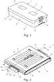
- a perspective view of a lid 1 according to the invention for a sterile container 2 is shown, which closes a trough-like receiving container 3.
- the receiving container 3 consists of a container base 4 and container walls 5 rising from this.
- the receiving container 3 and the lid 1 are closed by a closure 6.
- the lid 1 has a lid component 7, which is covered on the outside by two filter covers 8.
- one filter cover 8 (a gas exchange section on the lid component 7) or more than two filter covers 8 (more than two gas exchange sections on the lid component 7) can also be provided.
- Perforated or perforated plate-like sections are provided under the filter covers 8, on the lid component 7 in Fig. 1
- Perforated or perforated plate-like sections are provided.
- the cover component 7 completely covers the receiving container 3.
- the cover component 7 and the filter cover 8 are separate components.
- Fig. 2 shows an enlarged perspective view of a filter cover 8 attached to the cover component 7.
- the filter cover 8 shown is transparent and is made, for example, from an amorphous thermoplastic plastic using an injection molding process. Due to the transparency of the filter cover 8, perforations/holes 9 are visible, which are Gas exchange section 10 of the lid component 7 are provided. The perforations/holes 9 of the gas exchange section 10 allow media exchange during sterilization.
- the gas exchange section 10 is a section that protrudes from a cover component main plane 11.
- the filter cover 8 is rectangular and designed as a plate or disk (as a thin plate/disk). In particular, a height/thickness of the filter cover 10 is negligibly small in relation to its length and width.
- the filter cover 8 On two opposite, preferably shorter, (rectangular) sides, the filter cover 8 has a clip section 12, which is provided on a middle section of the respective (rectangular) side.
- the clip sections 12 of the filter cover 8 are each received in a form-fitting manner in clip receiving sections 13 of the cover component 7.
- the filter cover 8 On the (rectangular) sides of the filter cover 8, which have the clip sections 12, the filter cover is bent (over) and in sections in contact with the protruding gas exchange section 10 of the cover component and at the end with the main plane 11 of the cover component.
- the filter cover 8 On the other two, also opposite, preferably longer, (rectangular) sides, the filter cover 8 is arranged at a distance from the gas exchange section 10, in particular by about 2 mm. During sterilization, media can then be exchanged, in particular via the narrow gap 14 provided between the filter cover 8 and the gas exchange section 10.
- Each clip receiving section 13 has, among other things, a recess 15, which is composed of recess side surfaces 16 and a recess base surface 17. Projections 18 of the filter cover 8 are guided on two mutually opposite recess side surfaces 16. In other words, the projections 18 of the filter cover 8 are arranged adjacent to the two mutually opposite recess side surfaces 16 when the filter cover 8 is mounted on the cover component 7.
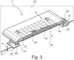
- Fig. 3 shows a line along the AA axis in Fig. 2 cut perspective view of the filter cover 8 attached to the lid component 7. It is initially recognizable here that on a bottom side/towards an inside of the lid/sterile container inside of the Gas exchange section 10, which has the holes/perforations 9, a filter 19 is arranged, which is designed as a rectangular, thin filter element and completely covers all holes/perforations 9 of the gas exchange section. Furthermore, in Fig. 3 clearer that the filter cover 8 and the gas exchange section 10 are spaced apart from each other or, in other words, a gap 14 is formed between the gas exchange section 10 and a filter cover main plane 20.
- the recess 15 has an S-shaped transition section 21 in addition to the recess side surfaces 16 and the recess base surface 17.
- the cover component 7 at the recess 15 transitions via recess side surfaces 16 from the cover component main plane 11 to the recess base surface 17 and via the S-shaped transition section 21 from the recess base surface 17 to the gas exchange section 10.
- the recess base surface 17 is offset from the cover component main plane 11 by a height H downwards/towards a cover inner side 22.
- the gas exchange section 10 is offset from the cover component main plane 11 by a height h upwards/towards a cover outer side 23.
- the recess base surface 17, the cover component main plane 11 and the gas exchange section 10 are parallel to one another.
- the S-shaped transition section 21 runs in an S-shape between the recess base area 17 and the gas exchange section 10.
- Fig. 3 shows how the clip sections 12 of the filter cover 8 are designed.
- the clip sections 12 are clamp-shaped/C-shaped end sections/(rectangular) side sections 24, which extend on two opposite (rectangular) sides of the filter cover in a clamp-like/C-shaped manner from the filter cover main plane 20 downwards/towards an inner side 22 of the cover.
- a gripping section 25 extends laterally outwardly from the clamp-shaped/C-shaped (rectangular) side sections 24. The gripping section 25 is parallel to the filter cover main plane 20.
- the clip-shaped/C-shaped (rectangular) side sections 24 of the filter cover 8 are clipped/clipped onto the S-shaped transition sections 21 of the cover component 7, or the C-shaped (rectangular) side sections 24 clip onto the S-shaped transition sections 21, so that the filter cover 8 and the cover component 7 are thereby positively connected to one another.
- the clipping/clipping in of the clip sections 12 of the filter cover 8 into the clip receiving sections 13 of the cover component 7 is made possible in particular by the elasticity of the amorphous thermoplastic used.
Landscapes
- Health & Medical Sciences (AREA)
- Life Sciences & Earth Sciences (AREA)
- Veterinary Medicine (AREA)
- Animal Behavior & Ethology (AREA)
- General Health & Medical Sciences (AREA)
- Public Health (AREA)
- Surgery (AREA)
- Epidemiology (AREA)
- Nuclear Medicine, Radiotherapy & Molecular Imaging (AREA)
- Engineering & Computer Science (AREA)
- Biomedical Technology (AREA)
- Heart & Thoracic Surgery (AREA)
- Medical Informatics (AREA)
- Molecular Biology (AREA)
- Closures For Containers (AREA)
- Packages (AREA)
- Apparatus For Disinfection Or Sterilisation (AREA)
- Filtering Of Dispersed Particles In Gases (AREA)
Claims (10)
- Couvercle de conception modulaire (1) pour un récipient stérile (2) avec :un composant de couvercle (7) qui présente au moins une section d'échange de gaz (10) sur laquelle au moins un appareil de filtre (19) peut être disposé, etau moins un cache de filtre (8) avec lequel l'au moins une section d'échange de gaz (10) peut être couverte sur un côté extérieur de couvercle (23), dans lequel le composant de couvercle (7) présente au moins une section de logement de clip (13) et le cache de filtre (8) au moins une section de clip (12), par l'intermédiaire desquelles le cache de filtre (8) peut être fixé au composant de couvercle (7) par complémentarité de formes, en particulier par clipsage, et peut être montée et démontée sans outils, caractérisé en ce queun évidement (15) en forme d'auge est prévu sur la section de logement de clip (13) du composant de couvercle (7), évidement sur lequel le composant de couvercle (7) passe d'un plan principal de composant de couvercle (11) à une surface de base d'évidement (17) décalée par rapport au plan principal de composant de couvercle (11) vers un côté intérieur de couvercle (22) et de la surface de base d'évidement (17) à la section d'échange de gaz (10) décalée par rapport au plan principal de composant de couvercle (11) vers un côté extérieur de couvercle (23) à travers une section de transition en forme de S (21).
- Couvercle de conception modulaire (1) selon la revendication 1, dans lequel la section de clip (12) du cache de filtre (8) est conçue en tant que section latérale (24) du cache de filtre (8) s'étendant à la manière d'une pince, et une section de préhension (25) faisant saillie latéralement vers l'extérieur est disposée sur la section latérale (24) s'étendant à la manière d'une pince, section de préhension qui peut être actionnée manuellement lors du montage et du démontage du cache de filtre (8) sur le composant de couvercle (7).
- Couvercle de conception modulaire (1) selon les revendications 1 et 2, dans lequel, à l'état monté du cache de filtre (8) sur le composant de couvercle (7), la section latérale (24) de la couverture de filtre (8) s'étendant à la manière d'une pince s'engage par complémentarité de formes dans la section de transition en forme de S (21) du composant de couvercle (7).
- Couvercle de conception modulaire (1) selon la revendication 1, dans lequel la section de clip (12) est conçue en tant que section latérale (24) de la couverture de filtre (8) s'étendant à la manière d'une pince et la section de logement de clip (13) présente la section de transition en forme de S (21), dans lequel, à l'état monté du cache de filtre (8) sur le composant de couvercle (7), la section latérale (24) du cache de filtre (8) s'étendant à la manière d'une pince s'engage dans la section de transition en forme de S (21) de la section de logement de clip (13).
- Couvercle de conception modulaire (1) selon l'une quelconque des revendications précédentes, dans lequel le cache de filtre (8) présente deux sections de clip (12) qui sont disposées sur des côtés et/ou des extrémités opposés, de préférence parallèles, du cache de filtre (8), et le composant de couvercle (7) présente deux sections de logement de clip (13) qui sont disposées sur des côtés et/ou des extrémités opposés, de préférence parallèles, de la section d'échange de gaz (10), et à l'état monté du cache de filtre(8) sur le composant de couvercle (7), les deux sections de clip (12) s'engagent dans les deux sections de logement de clip (13).
- Couvercle de conception modulaire (1) selon l'une quelconque des revendications précédentes, dans lequel le cache de filtre (8) est fabriqué en thermoplastique amorphe et est transparent pour le contrôle visuel de l'appareil de filtre (19) à partir du côté extérieur de couvercle (23) sans démontage préalable du cache de filtre (8) du composant de couvercle (7).
- Récipient stérile (2) avec une partie de récipient en forme d'auge (3) et un couvercle (1) selon l'une quelconque des revendications précédentes.
- Cache de filtre (8) pour un couvercle (1) selon l'une quelconque des revendications 1 à 6, pour couvrir complètement au moins une section d'échange de gaz (10) prévue sur un composant de couvercle (7) du couvercle de récipient stérile (1) sur un côté extérieur de couvercle (23) qui est fabriqué d'un seul tenant en matière plastique, caractérisé en ce que le cache de filtre (8) présente au moins deux sections de clip (12) disposées sur des côtés et/ou extrémités opposés du cache de filtre (8), sections qui sont adaptées pour s'engager par complémentarité de formes, en particulier par clipsage, dans deux sections de logement de clip (13) disposées sur le composant de couvercle (7) sur des côtés et/ou des extrémités opposés de la section d'échange de gaz (10), et par l'intermédiaire desquelles le cache de filtre (8) peut être monté et démonté sans outils sur le composant de couvercle (7), dans lequel
le cache de filtre (8) est une plaque rectangulaire dont la hauteur est petite par rapport à sa longueur et à sa largeur, et les sections de clip (12) sont conçues en tant que sections pliées à la manière d'une pince ou en forme de C à l'écart d'un plan principal de la couverture de filtre. - Cache de filtre (8) selon la revendication 8, dans lequel les sections de clip sont conçues en tant que sections latérales (24) du cache de filtre (8) s'étendant à la manière d'une pince et respectivement une section de préhension (25) faisant saillie latéralement vers l'extérieur est disposée sur les sections latérales (24) s'étendant à la manière d'une pince, section qui peut être actionnée manuellement lors du montage et du démontage du cache de filtre (8) sur le composant de couvercle (7).
- Cache de filtre (8) selon la revendication 8 ou 9 qui est en outre fabriqué à partir d'un thermoplastique amorphe et est transparent pour le contrôle visuel d'un appareil de filtre (19) pouvant être disposé sur un côté intérieur de couvercle (22) de la section d'échange de gaz (10) à partir d'un côté extérieur de couvercle (23) sans démontage préalable du cache de filtre (8) du composant de couvercle (7).
Applications Claiming Priority (2)
| Application Number | Priority Date | Filing Date | Title |
|---|---|---|---|
| DE102017117624.1A DE102017117624A1 (de) | 2017-08-03 | 2017-08-03 | Modular aufgebauter Deckel für einen Sterilbehälter und Filterabdeckung für einen solchen Deckel |
| PCT/EP2018/070732 WO2019025441A1 (fr) | 2017-08-03 | 2018-07-31 | Couvercle de conception modulaire pour conteneur de stérilisation et cache filtrant d'un tel couvercle |
Publications (3)
| Publication Number | Publication Date |
|---|---|
| EP3661449A1 EP3661449A1 (fr) | 2020-06-10 |
| EP3661449C0 EP3661449C0 (fr) | 2024-10-09 |
| EP3661449B1 true EP3661449B1 (fr) | 2024-10-09 |
Family
ID=63407174
Family Applications (1)
| Application Number | Title | Priority Date | Filing Date |
|---|---|---|---|
| EP18762009.1A Active EP3661449B1 (fr) | 2017-08-03 | 2018-07-31 | Couvercle de conception modulaire pour conteneur de stérilisation et cache filtrant d'un tel couvercle |
Country Status (5)
| Country | Link |
|---|---|
| US (2) | US11490982B2 (fr) |
| EP (1) | EP3661449B1 (fr) |
| CN (2) | CN116650691A (fr) |
| DE (1) | DE102017117624A1 (fr) |
| WO (1) | WO2019025441A1 (fr) |
Families Citing this family (1)
| Publication number | Priority date | Publication date | Assignee | Title |
|---|---|---|---|---|
| DE102021003190A1 (de) | 2021-06-21 | 2023-01-05 | Robert Simmoteit | Sterilisationsvorrichtung und Kontrolleinheit |
Family Cites Families (40)
| Publication number | Priority date | Publication date | Assignee | Title |
|---|---|---|---|---|
| US1316818A (en) * | 1919-09-23 | Quick-detachable shipping-case cover | ||
| US1468208A (en) * | 1921-08-22 | 1923-09-18 | Mueller William | Jar closure |
| US2963761A (en) * | 1958-03-31 | 1960-12-13 | Haydock Raymond | Tray clip |
| US2979554A (en) * | 1959-06-17 | 1961-04-11 | Bendix Corp | Insulated mounting clamp for electrical components |
| US3324853A (en) * | 1964-03-02 | 1967-06-13 | Sorenson Res Corp | Intravenous catheter protector unit |
| US3370815A (en) * | 1965-09-13 | 1968-02-27 | Lamb Co F Jos | Shock absorbing pad for conduit clamping device |
| US3544146A (en) * | 1968-10-07 | 1970-12-01 | Shell Oil Co | Container |
| JPS5872708A (ja) * | 1981-10-22 | 1983-04-30 | トヨタ自動車株式会社 | 2つ割型樹脂カバ− |
| US4452373A (en) * | 1982-06-15 | 1984-06-05 | Packaging By Forming Industries, Inc. | Jewelry box hinge structure |
| USD279959S (en) * | 1983-04-06 | 1985-08-06 | Nimlok Limited | Clip |
| FR2545564B1 (fr) * | 1983-05-03 | 1985-08-30 | Freyssinet Int Stup | Perfectionnements aux elements de repartition interposes entre les frettes et les corps frettes par celles-ci |
| US4560083A (en) * | 1984-01-16 | 1985-12-24 | Trw Inc. | Closure and method for an aperture |
| US4915913A (en) * | 1984-05-22 | 1990-04-10 | Genesis Medical Corporation | Medical sterilizer device with improved latch mechanism |
| US5080874A (en) * | 1984-11-05 | 1992-01-14 | Nichols Robert L | Medical instrument sterilization container |
| US6715628B1 (en) * | 1991-03-04 | 2004-04-06 | Steris Inc. | Contaminant plug for medical instrument sterilization containers |
| US5524755A (en) * | 1994-03-14 | 1996-06-11 | Deeds; Charles D. | Sterilization container |
| US5755484A (en) * | 1996-10-28 | 1998-05-26 | Ford Global Technologies, Inc. | Vehicle door intrusion beam |
| US5921422A (en) * | 1997-09-23 | 1999-07-13 | Hewlett-Packard Company | Enclosure with spring clamps and stands covering the clamps |
| DE10003092A1 (de) * | 1999-01-26 | 2000-09-07 | Paragon Medical Inc | Sterilisierungsbehälter |
| US7316506B2 (en) * | 2001-10-23 | 2008-01-08 | Illinois Tool Works Inc. | Dual temperature indicator stick holder |
| DE10156937A1 (de) * | 2001-11-15 | 2003-06-05 | Aesculap Ag & Co Kg | Sterilbehälter |
| DE10156935B4 (de) * | 2001-11-15 | 2004-02-26 | Aesculap Ag & Co. Kg | Sterilbehälter |
| ES2243794T3 (es) | 2001-11-15 | 2005-12-01 | AESCULAP AG & CO. KG | Recipiente esteril. |
| AU150046S (en) * | 2002-04-09 | 2002-12-05 | Paradigm Five Pty Ltd | A musical instrument support and stabiliser apparatus |
| DE202004002095U1 (de) * | 2004-02-12 | 2004-04-15 | Gottfried Storz Medizintechnik Gmbh & Co. Kg | Medizinischer Sterilisierbehälter mit Gasaustauschfilter |
| US7595032B2 (en) * | 2004-03-08 | 2009-09-29 | Banks Percival C | Protected seal for a filtered vent in a sterilization container |
| DE102004020803A1 (de) | 2004-04-16 | 2005-11-03 | Aesculap Ag & Co. Kg | Sterilbehälter |
| DE102004020805B3 (de) * | 2004-04-16 | 2006-01-19 | Aesculap Ag & Co. Kg | Sterilbehälter |
| CN201006022Y (zh) * | 2006-09-10 | 2008-01-16 | 刘宝敬 | 一种密封消毒装置 |
| CN201020055Y (zh) * | 2007-04-05 | 2008-02-13 | 北京白象新技术有限公司 | 并联式低温等离子体灭菌装置 |
| DE102008053301A1 (de) * | 2008-10-27 | 2010-04-29 | Medicon Eg. Chirurgiemechaniker-Genossenschaft | Behälter zum Sterilisieren und/oder Lagern von medizinischen Gegenständen |
| DE202010009925U1 (de) * | 2010-07-06 | 2010-10-14 | Gottfried Storz Medizintechnik Gmbh & Co. Kg | Medizinischer Sterilisierbehälter mit Gasaustauschfilter |
| DE102010037659A1 (de) * | 2010-09-20 | 2012-03-22 | Aesculap Ag | Sterilbehälter |
| DE202011001772U1 (de) | 2011-01-21 | 2011-04-07 | Gottfried Storz Medizintechnik Gmbh & Co. Kg | Sterilisierbehälter mit Filtereinheit |
| US8662455B2 (en) * | 2011-07-14 | 2014-03-04 | Raytheon Company | Spring clip retention systems suitable for usage within vehicles and guided munitions |
| USD691032S1 (en) * | 2012-01-18 | 2013-10-08 | Kevin F. Chen | Cable holder |
| DE102012101832A1 (de) * | 2012-03-05 | 2013-09-05 | Aesculap Ag | Chirurgischer Sterilisierbehälter und chirurgische Fluidextraktionsvorrichtung |
| DE202013007581U1 (de) * | 2013-08-23 | 2013-09-13 | Innovations-Medical Gmbh | Filterhalterung für Sterilcontainer |
| DE102013111979A1 (de) * | 2013-10-30 | 2015-04-30 | Aesculap Ag | Sterilanzeige für einen Sterilbehälter |
| EP3363521B1 (fr) * | 2015-04-10 | 2022-06-29 | MANN+HUMMEL GmbH | Élement de filtre et installation de filtre |
-
2017
- 2017-08-03 DE DE102017117624.1A patent/DE102017117624A1/de not_active Withdrawn
-
2018
- 2018-07-31 CN CN202310624829.8A patent/CN116650691A/zh active Pending
- 2018-07-31 CN CN201880050677.2A patent/CN110996830B/zh active Active
- 2018-07-31 US US16/636,107 patent/US11490982B2/en active Active
- 2018-07-31 WO PCT/EP2018/070732 patent/WO2019025441A1/fr not_active Ceased
- 2018-07-31 EP EP18762009.1A patent/EP3661449B1/fr active Active
-
2022
- 2022-09-22 US US17/950,901 patent/US12303306B2/en active Active
Also Published As
| Publication number | Publication date |
|---|---|
| US20200383745A1 (en) | 2020-12-10 |
| US20230025190A1 (en) | 2023-01-26 |
| US11490982B2 (en) | 2022-11-08 |
| EP3661449A1 (fr) | 2020-06-10 |
| CN110996830A (zh) | 2020-04-10 |
| DE102017117624A1 (de) | 2019-02-07 |
| US12303306B2 (en) | 2025-05-20 |
| EP3661449C0 (fr) | 2024-10-09 |
| CN110996830B (zh) | 2023-04-28 |
| WO2019025441A1 (fr) | 2019-02-07 |
| CN116650691A (zh) | 2023-08-29 |
Similar Documents
| Publication | Publication Date | Title |
|---|---|---|
| EP2618854B1 (fr) | Contenant stérile | |
| EP3797638A1 (fr) | Pot de crème | |
| EP0588228A1 (fr) | Récipients stérilisable pour trousses et instruments médicaux et chirurgicaux | |
| EP2252183B1 (fr) | Élément annulaire et couvercle correspondant | |
| WO2015091928A1 (fr) | Dispositif de recouvrement, en particulier couvercle servant à couvrir des récipients réactionnels | |
| DE2740335A1 (de) | Wegwerfbehaelter fuer einmalkanuelen | |
| EP2334567B1 (fr) | Poignée de manutention pour conteneur | |
| EP3551236B1 (fr) | Interface pour fixer des éléments rapportés sur des conteneurs stériles | |
| EP3725338B1 (fr) | Récipient stérile médical | |
| DE102006030056B3 (de) | Mikrotiterplatte mit Rührelementen | |
| EP3661449B1 (fr) | Couvercle de conception modulaire pour conteneur de stérilisation et cache filtrant d'un tel couvercle | |
| DE2119359A1 (de) | Flaschenöffner. AnmrHuff, Otto, 4630 Bochum | |
| DE202004002095U1 (de) | Medizinischer Sterilisierbehälter mit Gasaustauschfilter | |
| DE3833663A1 (de) | Spender fuer desinfektionsmittel, seifencreme, handcreme, hautpflegemittel und dgl. | |
| EP3873373B1 (fr) | Système de récipient et procédé pour la formation d'une poignée dans un récipient | |
| CH628255A5 (en) | Interconnected set of vessels with a plurality of reaction vessels, and retaining appliance for at least one such interconnected set | |
| DE102005005468B4 (de) | Spritze | |
| DE2821893A1 (de) | Klammer, insbesondere chirurgische klammer | |
| EP3111964A1 (fr) | Mecanisme de verrouillage et crepine dotee d'un couvercle incluant le mecanisme de verrouillage | |
| EP3419546B1 (fr) | Couvercle de récipient stérile comportant un cache extérieur | |
| DE19608110B4 (de) | Verwendung eines Probenbehältnisses | |
| DE3918147C2 (fr) | ||
| DE9212315U1 (de) | Sterilisierfähiges Behältnis für einzelne medizinische und chirurgische Bestecke, Instrumente und Geräte | |
| DE202016107365U1 (de) | Deckel für einen Behälter | |
| DE102023109009A1 (de) | Greifereinrichtung zum Greifen von Behältern |
Legal Events
| Date | Code | Title | Description |
|---|---|---|---|
| STAA | Information on the status of an ep patent application or granted ep patent |
Free format text: STATUS: UNKNOWN |
|
| STAA | Information on the status of an ep patent application or granted ep patent |
Free format text: STATUS: THE INTERNATIONAL PUBLICATION HAS BEEN MADE |
|
| PUAI | Public reference made under article 153(3) epc to a published international application that has entered the european phase |
Free format text: ORIGINAL CODE: 0009012 |
|
| STAA | Information on the status of an ep patent application or granted ep patent |
Free format text: STATUS: REQUEST FOR EXAMINATION WAS MADE |
|
| 17P | Request for examination filed |
Effective date: 20200227 |
|
| AK | Designated contracting states |
Kind code of ref document: A1 Designated state(s): AL AT BE BG CH CY CZ DE DK EE ES FI FR GB GR HR HU IE IS IT LI LT LU LV MC MK MT NL NO PL PT RO RS SE SI SK SM TR |
|
| AX | Request for extension of the european patent |
Extension state: BA ME |
|
| RIN1 | Information on inventor provided before grant (corrected) |
Inventor name: SCHWEIZER, MATTHIAS Inventor name: THOMAS, STEFAN Inventor name: GRAY-DREIZLER, JOHN Inventor name: ELISCH, ANDREAS Inventor name: BERNAUER, BETINA Inventor name: BOHNENSTENGEL, PHILIPP Inventor name: HENKE, MATTHIAS Inventor name: STERK, THOMAS |
|
| DAV | Request for validation of the european patent (deleted) | ||
| DAX | Request for extension of the european patent (deleted) | ||
| GRAP | Despatch of communication of intention to grant a patent |
Free format text: ORIGINAL CODE: EPIDOSNIGR1 |
|
| STAA | Information on the status of an ep patent application or granted ep patent |
Free format text: STATUS: GRANT OF PATENT IS INTENDED |
|
| INTG | Intention to grant announced |
Effective date: 20240314 |
|
| GRAJ | Information related to disapproval of communication of intention to grant by the applicant or resumption of examination proceedings by the epo deleted |
Free format text: ORIGINAL CODE: EPIDOSDIGR1 |
|
| STAA | Information on the status of an ep patent application or granted ep patent |
Free format text: STATUS: REQUEST FOR EXAMINATION WAS MADE |
|
| GRAP | Despatch of communication of intention to grant a patent |
Free format text: ORIGINAL CODE: EPIDOSNIGR1 |
|
| STAA | Information on the status of an ep patent application or granted ep patent |
Free format text: STATUS: GRANT OF PATENT IS INTENDED |
|
| INTC | Intention to grant announced (deleted) | ||
| INTG | Intention to grant announced |
Effective date: 20240513 |
|
| GRAS | Grant fee paid |
Free format text: ORIGINAL CODE: EPIDOSNIGR3 |
|
| GRAA | (expected) grant |
Free format text: ORIGINAL CODE: 0009210 |
|
| STAA | Information on the status of an ep patent application or granted ep patent |
Free format text: STATUS: THE PATENT HAS BEEN GRANTED |
|
| AK | Designated contracting states |
Kind code of ref document: B1 Designated state(s): AL AT BE BG CH CY CZ DE DK EE ES FI FR GB GR HR HU IE IS IT LI LT LU LV MC MK MT NL NO PL PT RO RS SE SI SK SM TR |
|
| REG | Reference to a national code |
Ref country code: CH Ref legal event code: EP |
|
| REG | Reference to a national code |
Ref country code: DE Ref legal event code: R096 Ref document number: 502018015217 Country of ref document: DE |
|
| REG | Reference to a national code |
Ref country code: IE Ref legal event code: FG4D Free format text: LANGUAGE OF EP DOCUMENT: GERMAN |
|
| U01 | Request for unitary effect filed |
Effective date: 20241105 |
|
| U07 | Unitary effect registered |
Designated state(s): AT BE BG DE DK EE FI FR IT LT LU LV MT NL PT RO SE SI Effective date: 20241114 |
|
| PG25 | Lapsed in a contracting state [announced via postgrant information from national office to epo] |
Ref country code: IS Free format text: LAPSE BECAUSE OF FAILURE TO SUBMIT A TRANSLATION OF THE DESCRIPTION OR TO PAY THE FEE WITHIN THE PRESCRIBED TIME-LIMIT Effective date: 20250209 Ref country code: HR Free format text: LAPSE BECAUSE OF FAILURE TO SUBMIT A TRANSLATION OF THE DESCRIPTION OR TO PAY THE FEE WITHIN THE PRESCRIBED TIME-LIMIT Effective date: 20241009 |
|
| PG25 | Lapsed in a contracting state [announced via postgrant information from national office to epo] |
Ref country code: ES Free format text: LAPSE BECAUSE OF FAILURE TO SUBMIT A TRANSLATION OF THE DESCRIPTION OR TO PAY THE FEE WITHIN THE PRESCRIBED TIME-LIMIT Effective date: 20241009 |
|
| PG25 | Lapsed in a contracting state [announced via postgrant information from national office to epo] |
Ref country code: NO Free format text: LAPSE BECAUSE OF FAILURE TO SUBMIT A TRANSLATION OF THE DESCRIPTION OR TO PAY THE FEE WITHIN THE PRESCRIBED TIME-LIMIT Effective date: 20250109 |
|
| PG25 | Lapsed in a contracting state [announced via postgrant information from national office to epo] |
Ref country code: GR Free format text: LAPSE BECAUSE OF FAILURE TO SUBMIT A TRANSLATION OF THE DESCRIPTION OR TO PAY THE FEE WITHIN THE PRESCRIBED TIME-LIMIT Effective date: 20250110 |
|
| PG25 | Lapsed in a contracting state [announced via postgrant information from national office to epo] |
Ref country code: PL Free format text: LAPSE BECAUSE OF FAILURE TO SUBMIT A TRANSLATION OF THE DESCRIPTION OR TO PAY THE FEE WITHIN THE PRESCRIBED TIME-LIMIT Effective date: 20241009 |
|
| PG25 | Lapsed in a contracting state [announced via postgrant information from national office to epo] |
Ref country code: RS Free format text: LAPSE BECAUSE OF FAILURE TO SUBMIT A TRANSLATION OF THE DESCRIPTION OR TO PAY THE FEE WITHIN THE PRESCRIBED TIME-LIMIT Effective date: 20250109 |
|
| PG25 | Lapsed in a contracting state [announced via postgrant information from national office to epo] |
Ref country code: SM Free format text: LAPSE BECAUSE OF FAILURE TO SUBMIT A TRANSLATION OF THE DESCRIPTION OR TO PAY THE FEE WITHIN THE PRESCRIBED TIME-LIMIT Effective date: 20241009 |
|
| PG25 | Lapsed in a contracting state [announced via postgrant information from national office to epo] |
Ref country code: SK Free format text: LAPSE BECAUSE OF FAILURE TO SUBMIT A TRANSLATION OF THE DESCRIPTION OR TO PAY THE FEE WITHIN THE PRESCRIBED TIME-LIMIT Effective date: 20241009 |
|
| PG25 | Lapsed in a contracting state [announced via postgrant information from national office to epo] |
Ref country code: CZ Free format text: LAPSE BECAUSE OF FAILURE TO SUBMIT A TRANSLATION OF THE DESCRIPTION OR TO PAY THE FEE WITHIN THE PRESCRIBED TIME-LIMIT Effective date: 20241009 |
|
| PLBE | No opposition filed within time limit |
Free format text: ORIGINAL CODE: 0009261 |
|
| STAA | Information on the status of an ep patent application or granted ep patent |
Free format text: STATUS: NO OPPOSITION FILED WITHIN TIME LIMIT |
|
| U20 | Renewal fee for the european patent with unitary effect paid |
Year of fee payment: 8 Effective date: 20250729 |
|
| 26N | No opposition filed |
Effective date: 20250710 |
|
| REG | Reference to a national code |
Ref country code: CH Ref legal event code: H13 Free format text: ST27 STATUS EVENT CODE: U-0-0-H10-H13 (AS PROVIDED BY THE NATIONAL OFFICE) Effective date: 20260224 |
|
| GBPC | Gb: european patent ceased through non-payment of renewal fee |
Effective date: 20250731 |
|
| PG25 | Lapsed in a contracting state [announced via postgrant information from national office to epo] |
Ref country code: GB Free format text: LAPSE BECAUSE OF NON-PAYMENT OF DUE FEES Effective date: 20250731 |
|
| PG25 | Lapsed in a contracting state [announced via postgrant information from national office to epo] |
Ref country code: CH Free format text: LAPSE BECAUSE OF NON-PAYMENT OF DUE FEES Effective date: 20250731 |