EP3661452B1 - Pilier destiné à maintenir une prothèse dentaire sur un implant de mâchoire - Google Patents
Pilier destiné à maintenir une prothèse dentaire sur un implant de mâchoire Download PDFInfo
- Publication number
- EP3661452B1 EP3661452B1 EP18745622.3A EP18745622A EP3661452B1 EP 3661452 B1 EP3661452 B1 EP 3661452B1 EP 18745622 A EP18745622 A EP 18745622A EP 3661452 B1 EP3661452 B1 EP 3661452B1
- Authority
- EP
- European Patent Office
- Prior art keywords
- abutment
- display element
- indexing
- central axis
- section
- Prior art date
- Legal status (The legal status is an assumption and is not a legal conclusion. Google has not performed a legal analysis and makes no representation as to the accuracy of the status listed.)
- Active
Links
Images


Classifications
-
- A—HUMAN NECESSITIES
- A61—MEDICAL OR VETERINARY SCIENCE; HYGIENE
- A61C—DENTISTRY; APPARATUS OR METHODS FOR ORAL OR DENTAL HYGIENE
- A61C13/00—Dental prostheses; Making same
- A61C13/0003—Making bridge-work, inlays, implants or the like
- A61C13/0004—Computer-assisted sizing or machining of dental prostheses
-
- A—HUMAN NECESSITIES
- A61—MEDICAL OR VETERINARY SCIENCE; HYGIENE
- A61C—DENTISTRY; APPARATUS OR METHODS FOR ORAL OR DENTAL HYGIENE
- A61C13/00—Dental prostheses; Making same
- A61C13/0003—Making bridge-work, inlays, implants or the like
- A61C13/0006—Production methods
- A61C13/0019—Production methods using three dimensional printing
-
- A—HUMAN NECESSITIES
- A61—MEDICAL OR VETERINARY SCIENCE; HYGIENE
- A61C—DENTISTRY; APPARATUS OR METHODS FOR ORAL OR DENTAL HYGIENE
- A61C8/00—Means to be fixed to the jaw-bone for consolidating natural teeth or for fixing dental prostheses thereon; Dental implants; Implanting tools
- A61C8/0001—Impression means for implants, e.g. impression coping
-
- A—HUMAN NECESSITIES
- A61—MEDICAL OR VETERINARY SCIENCE; HYGIENE
- A61C—DENTISTRY; APPARATUS OR METHODS FOR ORAL OR DENTAL HYGIENE
- A61C8/00—Means to be fixed to the jaw-bone for consolidating natural teeth or for fixing dental prostheses thereon; Dental implants; Implanting tools
- A61C8/0048—Connecting the upper structure to the implant, e.g. bridging bars
- A61C8/005—Connecting devices for joining an upper structure with an implant member, e.g. spacers
- A61C8/0056—Connecting devices for joining an upper structure with an implant member, e.g. spacers diverging in the apical direction of the implant or abutment
-
- A—HUMAN NECESSITIES
- A61—MEDICAL OR VETERINARY SCIENCE; HYGIENE
- A61C—DENTISTRY; APPARATUS OR METHODS FOR ORAL OR DENTAL HYGIENE
- A61C8/00—Means to be fixed to the jaw-bone for consolidating natural teeth or for fixing dental prostheses thereon; Dental implants; Implanting tools
- A61C8/0048—Connecting the upper structure to the implant, e.g. bridging bars
- A61C8/005—Connecting devices for joining an upper structure with an implant member, e.g. spacers
- A61C8/006—Connecting devices for joining an upper structure with an implant member, e.g. spacers with polygonal positional means, e.g. hexagonal or octagonal
-
- A—HUMAN NECESSITIES
- A61—MEDICAL OR VETERINARY SCIENCE; HYGIENE
- A61C—DENTISTRY; APPARATUS OR METHODS FOR ORAL OR DENTAL HYGIENE
- A61C8/00—Means to be fixed to the jaw-bone for consolidating natural teeth or for fixing dental prostheses thereon; Dental implants; Implanting tools
- A61C8/0048—Connecting the upper structure to the implant, e.g. bridging bars
- A61C8/005—Connecting devices for joining an upper structure with an implant member, e.g. spacers
- A61C8/0068—Connecting devices for joining an upper structure with an implant member, e.g. spacers with an additional screw
-
- A—HUMAN NECESSITIES
- A61—MEDICAL OR VETERINARY SCIENCE; HYGIENE
- A61C—DENTISTRY; APPARATUS OR METHODS FOR ORAL OR DENTAL HYGIENE
- A61C8/00—Means to be fixed to the jaw-bone for consolidating natural teeth or for fixing dental prostheses thereon; Dental implants; Implanting tools
- A61C8/0048—Connecting the upper structure to the implant, e.g. bridging bars
- A61C8/005—Connecting devices for joining an upper structure with an implant member, e.g. spacers
- A61C8/0069—Connecting devices for joining an upper structure with an implant member, e.g. spacers tapered or conical connection
-
- A—HUMAN NECESSITIES
- A61—MEDICAL OR VETERINARY SCIENCE; HYGIENE
- A61C—DENTISTRY; APPARATUS OR METHODS FOR ORAL OR DENTAL HYGIENE
- A61C9/00—Impression cups, i.e. impression trays; Impression methods
- A61C9/004—Means or methods for taking digitized impressions
- A61C9/0046—Data acquisition means or methods
- A61C9/0053—Optical means or methods, e.g. scanning the teeth by a laser or light beam
-
- B—PERFORMING OPERATIONS; TRANSPORTING
- B33—ADDITIVE MANUFACTURING TECHNOLOGY
- B33Y—ADDITIVE MANUFACTURING, i.e. MANUFACTURING OF THREE-DIMENSIONAL [3D] OBJECTS BY ADDITIVE DEPOSITION, ADDITIVE AGGLOMERATION OR ADDITIVE LAYERING, e.g. BY 3D PRINTING, STEREOLITHOGRAPHY OR SELECTIVE LASER SINTERING
- B33Y50/00—Data acquisition or data processing for additive manufacturing
-
- B—PERFORMING OPERATIONS; TRANSPORTING
- B33—ADDITIVE MANUFACTURING TECHNOLOGY
- B33Y—ADDITIVE MANUFACTURING, i.e. MANUFACTURING OF THREE-DIMENSIONAL [3D] OBJECTS BY ADDITIVE DEPOSITION, ADDITIVE AGGLOMERATION OR ADDITIVE LAYERING, e.g. BY 3D PRINTING, STEREOLITHOGRAPHY OR SELECTIVE LASER SINTERING
- B33Y80/00—Products made by additive manufacturing
Definitions
- the present invention is defined by the claims and relates to an abutment for holding a jaw implant, a display element for coupling to the abutment and a tooth model system.
- Abutments are used to attach artificial individual teeth, groups of individual teeth or entire dental prostheses (dentures) in the patient's mouth.
- jaw implants are inserted (screwed into) the jawbone, to which the abutments (artificial tooth stumps) are attached.
- This can be several implants or abutments for an entire dental prosthesis.
- An abutment is a kind of intermediate piece between a jaw implant and an individually manufactured dental prosthesis and is usually connected to both the implant and the dental prosthesis by screwing.
- a display element also known as a "ScanBody” or “ScanMarker”
- ScanBody is designed as a post with one or more surfaces, for example, and is recognized when the teeth are scanned. It shows the exact position and orientation of the implant and is thus used for the later exact positioning of an abutment in (or on) the print model.
- the denture is then created on the abutment in the print model and later screwed together with the abutment into the implant in the patient's jaw.
- angled abutments have an apical section facing the jaw that is at an angle to a coronal section facing the denture. This makes it possible to deal with different jaw shapes that require the insertion of implants in different directions. In the case of jaw shapes and denture positions where only a few places are suitable for inserting implants, the use of angled abutments can often prevent blockages when inserting the denture.
- a superstructure carrier and a method for its production are disclosed.
- An artificial crown or a composite of an adhesive body and a crown is arranged on or at the superstructure carrier.
- the superstructure carrier has a first structure at least in some areas in the adhesive body and/or crown-bearing area.
- a second structure is arranged on the superstructure carrier in the area facing the implant body.
- the superstructure carrier can be manufactured economically as part of a prosthetic tooth replacement using the method disclosed.
- An abutment attachment for a jaw implant comprises a fastening section for fastening the abutment attachment to the jaw implant and an adhesive base laterally offset from the fastening section for adhering a crown adhesive body as a base for a dental crown or for adhering a healing cap adhesive body.
- WO 2018/007316 A1 discloses an abutment base for restorative dental treatment.
- the abutment base comprises an implant section oriented around a first axis, which can be attached to a dental implant, and a crown section oriented around a second axis, which can be attached to a dental prosthesis.
- the two axes of the implant section and the crown section are not aligned with each other.
- the stop base has a central opening which extends over its entire length and is suitable for allowing the passage of a tool such as a screwdriver.
- a second indexing element is formed as a recess in the circumference of a coronal portion and a boundary surface of a first recess runs parallel to a second central axis and the boundary surface comprises a wave structure and is corrugated in a direction which runs perpendicular to and at a distance from the second central axis.
- EP 3 363 406 A2 published on 18.10.2017 , claims priority from 17.02.2017 and is prior art under Article 54(3) EPC and does not disclose a boundary surface of a recess which is corrugated in a direction which is perpendicular to and at a distance from a second central axis.
- the object is further achieved by a display element according to claim 8.
- the invention relates to a tooth model system according to claim 13.
- Disclosed and not claimed is a method for producing a dental prosthesis.
- an indexing element is provided in an angled abutment.
- the indexing element is located in the lateral surface of the coronal section.
- a lateral surface is understood to be the outer surface or the circumference of the body.
- the indexing element is located in this surface.
- the indexing element can be designed as a projection or as a recess, so that the lateral surface runs irregularly.
- the lateral surface can comprise a first part that corresponds to the lateral or outer surface of an original body, and a second part that corresponds to a surface that was created by removing (recess) or adding (protrusion) material from/to the original body.
- the indexing element can be designed as a geometric shape in a cross-section of the coronal section, for example as a hexagon, octagon or square.
- the indexing element interacts with a display element (ScanBody) and indicates to this display element the orientation of the apical section, i.e. the orientation of the jaw implant.
- An orientation of the first central axis is understood here to mean in particular an angle specification in relation to the position and orientation of the second central axis, which corresponds to the orientation of the display element.
- the orientation preferably comprises the Specifying an angle of a projection of the first central axis into a plane that is perpendicular to the second central axis. Apart from specifying an angle, the alignment can also be determined in another way.
- the alignment of the first central axis is clearly defined by means of such an angle and based on a known angle between the two central axes.
- the indexing element in the lateral surface of the coronal section is indexed relative to the apical section.
- the alignment of the first central axis or the jaw implant can also be determined.
- a display element coupled to the abutment is aligned using the indexing element.
- the indexing element specifies a clear alignment of the display element on the abutment, so that the alignment of the first central axis can also be calculated based on the alignment of the display element.
- the indexing element according to the invention can interact with a corresponding, correspondingly designed indexing coupling on the display element.
- the indexing element and indexing coupling determine the orientation of the display element based on the orientation of the apical section or the first central axis by means of a positive fit.
- the orientation of the first central axis can be calculated based on the orientation of the display element that can be determined in the scanning process.
- the invention allows digital work.
- a digital scanning process can be used to automatically generate a print model. This minimizes the effort involved in producing the print model or dentures.
- High-quality dentures can be produced because it is possible to precisely adjust the panels to the jaw or gums of a person.
- the indexing element is designed as a first recess in the circumference of the coronal section.
- a recess is understood to be in particular an indentation or a dent in the lateral surface.
- Positioning in the circumference means that a section of an essentially rotationally symmetrical body is removed or removed. A part of the original lateral surface or the material in the coronal area is therefore missing.
- a particular advantage here is that compatibility with standard coupling points on a dental prosthesis is maintained, since material is only removed from the original shape, not added.
- the abutment comprises a second indexing element, which is designed as a second recess in the circumference of the coronal section.
- the presence of two indexing elements ensures a high level of positioning security during Coupling of the display element to the abutment is ensured.
- the size of usual abutments is in the range of a few millimeters.
- a coronal section of a conventional abutment can, for example, have a diameter of approximately 5 mm in a plane perpendicular to the second central axis. In order to create a positive connection between the recess and the corresponding projection on the display element, it is advantageous to use two recesses. Stability is increased. Positional security is guaranteed.
- the first recess and the second recess have a different size, a different shape and/or are arranged at an angle other than 180° with respect to the second central axis in order to clearly specify the orientation of the display element that can be coupled.
- the two recesses can be of different sizes, have different shapes or can be arranged at an angle other than 180° to one another. All options allow the display element to only be coupled to the abutment if the display element is placed in the predefined position. A clear coupling is achieved.
- the coronal section comprises a truncated cone-shaped region that widens in the direction of the apical section and in which the indexing element is arranged.
- the so-called multi-unit abutments have now become a kind of industry standard in the field of abutments.
- an interface for coupling to the dental prosthesis is located in the coronal section.
- a truncated cone-shaped or conical region that widens in the direction of the apical section is preferably provided for this purpose.
- Such a truncated cone-shaped area creates compatibility between the abutment and the denture.
- the truncated cone-shaped design ensures a concentric arrangement of the coronal section and the bulge in the denture when tightening a screw connection.
- the indexing element is arranged in the truncated cone-shaped area. This means that a concentric arrangement of the display element and the coronal section can also be ensured when the display element is coupled.
- a boundary surface of the first and/or second recess runs parallel to the second central axis.
- a boundary surface is a part of the outer surface of the abutment in the coronal section. The boundary surface delimits the recess from the coronal area of the abutment, thus forming the outer shape of the recess.
- the boundary surface is the surface or part of the outer surface that is newly created by the recess. This boundary surface runs parallel to the second central axis.
- the boundary surface comprises a wave structure which is preferably symmetrical with respect to a plane of symmetry of the first and/or second recess.
- a wave structure is understood to be a regularly curved structure with several peaks and valleys.
- the parallel alignment of the boundary surface to the second central axis is maintained.
- the boundary surface is wavy in a direction which runs perpendicularly and at a distance from the second central axis.
- the abutment comprises a stop surface that is aligned perpendicular to the second central axis and runs around the second central axis for attaching the denture.
- a stop surface ensures that the denture and the display element can be firmly connected to the abutment in a clear orientation during the digital scanning process.
- a correspondingly designed stop surface on the denture or on the display element rests on the stop surface of the abutment. A stable anchoring of the denture and also of the display element is ensured.
- the abutment also advantageously comprises a step that runs parallel to the stop surface between the indexing element and the stop surface.
- the step between the indexing element and the stop surface is particularly advantageous if a recess is provided as the indexing element, which is usually produced in a milling process. Such a milling process requires a tolerance when milling.
- a step is retained between the stop surface and the recess, which represents a safety buffer for tolerances when milling the recess. This ensures that the stop surface is not damaged or scratched. The manufacturing and scrap costs are minimized.
- the abutment comprises a first bore extending along the first central axis through the coronal section and the apical section for receiving a fastening element for fastening the abutment to the jaw implant, wherein the first bore penetrates a lateral surface of the coronal section; and preferably a diameter of the first bore in the apical section is smaller than a diameter of the first bore in the coronal section.
- a Fastening element, in particular a screw, for attaching the abutment to the jaw implant must be inserted through the abutment. Since the abutment is angled, the hole penetrates the outer surface in the coronal section.
- a segment of the lateral surface of the coronal section interrupted by the first bore is smaller than a segment of the lateral surface of the coronal section interrupted by the first recess.
- the abutment comprises a second bore with an internal thread running along the second central axis through the coronal section for screwing on the dental prosthesis.
- the dental prosthesis is normally screwed directly into the second bore.
- the use of an internal thread can ensure easy assembly of the dental prosthesis.
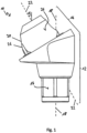
- an abutment 10 for holding a dental prosthesis in a jaw implant is shown.
- the abutment 10 comprises an apical section 12, i.e. a section that faces the jaw and is attached to the jaw implant.
- the abutment 10 also comprises a coronal section 14, i.e. a section that faces the tooth crown or the dental prosthesis and to which the dental prosthesis is attached.
- the two sections 12, 14 of the abutment 10 are firmly connected to one another and designate parts of a body.
- the apical section 12 is essentially cylindrical in structure, wherein in the area of the coupling to the jaw implant in the embodiment shown, several flat outer surfaces 16 are provided, which interact with a correspondingly designed jaw implant in order to prevent the abutment 10 from twisting relative to the jaw implant.
- the apical section 12 is constructed along a first central axis 18.
- the first central axis 18 is a vertical in the illustration shown.
- the coronal section 14 comprises a truncated cone-shaped region 20 which, as a cone, engages in a correspondingly shaped bulge in the dental prosthesis and can be fastened to the dental prosthesis.
- the coronal section 14 is constructed along a second central axis 22 which is at an angle to the first central axis 18.
- the angle between the central axes is to be selected such that the two central axes 18, 22 do not run parallel to one another.
- both central axes 18, 22 lie in one plane so that there is an intersection point of the central axes.
- both the apical section 12 and the coronal section 14 are normally not rotationally symmetrical to their central axes. Nevertheless, both sections are essentially cylindrical in shape.
- the present invention relates to angled abutments, i.e. abutments in which the first central axis 18 and the second central axis 22 are at an angle ⁇ to each other.
- Typical angles are, for example, 15°-45°, 20°-40°, 25°-35°, preferably 30°. It goes without saying that other angles are also possible and advantageous.
- the angular position of the two central axes 18, 22 enables the abutment 10 to be used even with jaw shapes that leave little room for maneuver with regard to the positioning and alignment of the jaw implant and where it is necessary for several jaw implants to be inserted into the jaw in different directions. Angled abutments are also used when the position of the jaw implants is limited by the size and type of dental prosthesis required.
- the illustrated embodiment of the abutment 10 according to the invention is designed as a so-called multi-unit abutment.
- This multi-unit has established itself as a quasi-standard, which is offered by various manufacturers, and is characterized in particular by the truncated cone-shaped area 20 in the coronal section 14.
- the connection points provided accordingly on the dental prosthesis are usually designed as recesses which receive the coronal section of the abutment and in which the coronal section is anchored.
- the abutment 10 comprises an indexing element 24 which is arranged in a lateral surface 26 of the coronal section 14.
- the indexing element 24 is designed as a first recess in the circumference of the coronal section 14.
- a piece of the truncated cone is milled off parallel to the second central axis 22. Because the indexing element 24 is designed as such a recess, the coronal section 14 can still be fitted into the same opening in a dental prosthesis.
- a cavity is merely created at the location of the first recess within the opening in the dental prosthesis. However, an adjustment of the dental prosthesis or the further manufacturing process is not necessary. Compatibility is guaranteed.
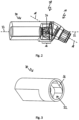
- the dental model system 28 in addition to the abutment 10, the dental model system 28 also includes a display element 30, which can be coupled to the coronal section 14 in a digital scanning process for the production of a print model.
- a display element 30 can be coupled to the coronal section 14 in a digital scanning process for the production of a print model.
- a digital To carry out a scanning process in which the situation is recorded automatically.
- a computer model is created on the basis of which a 3D print can then be generated.
- a display element 30 (ScanBody) is coupled to the abutment 10.
- the display element 30 is scanned, recognized by means of a corresponding computer program and can then serve as a basis for determining the position of the abutment and the alignment of the second central axis.
- the display element 30 In previous tooth model systems, it was not possible to determine the position or orientation of the first central axis 18 in relation to the second central axis 22 based on a scan of the display element 30.
- the second central axis 22 corresponds to a central axis of the display element 30. Due to the conical design of the coupling, the display element could be rotated about the second central axis when coupled. It was not possible to deduce the orientation of the first central axis and thus the position of the abutment or the position of the jaw implant based on the orientation and position of the coronal region or the second central axis that could be detected during scanning. This rotation is prevented by the indexing element 24.
- the position and orientation of the display element 30 relative to the abutment 10 or its second central axis 18 are unambiguous. Therefore, the orientation of the first central axis 18 can be deduced from the position and orientation of the first central axis 18, which corresponds to the position and axis of the display element 30.
- the orientation can be determined in the form of an angle in a plane perpendicular to the second central axis 22.
- the orientation can be specified in Cartesian or polar coordinates and corresponding reference systems. Processing is preferably automated. Consequently, the abutment 10 according to the invention can be used with standard prostheses, which have recesses or a blind hole for connection to multi-unit abutments.
- the display element 30 comprises a coupling region 32 in the form of an opening into which the coronal section of the abutment 10 can be received.
- an indexing coupling 34 is arranged, which corresponds to the indexing element 24 on the abutment.
- the indexing coupling 34 preferably corresponds to a projection in a coupling region 32 of a display element 30.
- a view of the abutment 10 according to the invention is shown in the direction of the first central axis 18.
- Both the apical section 12 and the coronal section 14 are traversed by a first bore 36, which runs along the first central axis 18 and is arranged concentrically to it.
- the first bore 36 serves to accommodate a fastening element by means of which the abutment 10 can be fastened to the jaw implant.
- a detachable fastening is understood in particular to mean screwing on. However, other types of fastening or coupling are also conceivable.
- a screw is used for fastening.
- the head of the screw is preferably received within the abutment 10 in such a way that a diameter D1 of the first hole in the apical section of the abutment is smaller than a diameter D2 of the first hole in the coronal section.
- the screw head then rests on the resulting shoulder and is located within the abutment 10.
- a second bore 38 is provided for fastening the abutment 10 to the dental prosthesis, which runs along the second central axis 22.
- the second bore 38 has an internal thread.
- the first bore 36 penetrates the outer surface 26 of the coronal section.
- an indexing element 24 designed as a recess is provided.
- the recess is located in the truncated cone-shaped region 20 in the coronal section of the abutment 10. A section of the truncated cone is missing, so that a boundary surface is created.
- the indexing element 24 or the recess is dimensioned such that an interrupted segment S1 of the lateral surface 26 through the recess is larger than a segment S2 of the lateral surface 26 interrupted by the first bore 36, which in the example shown corresponds in its maximum extent perpendicular to the first central axis 18 to the diameter D2 of the first bore 36 in the coronal section 14.
- the indexing element 24 is, so to speak, divided into two parts by the first bore 36. This size ratio ensures that the indexing coupling of the display element 30 cannot already engage in the interruption of the lateral surface 26 of the coronal section formed by the first bore 36. This results in a clear positioning of the display element 30.
- FIGS 5a and 5b Two embodiments of an abutment 10 according to the invention are shown, in each of which two indexing elements 24 are arranged in the lateral surface 26 of the coronal section. Shown in the Figures 5a and 5b each a plan view of the coronal section 14 in the direction of the second central axis 22. For the sake of clarity, reference is made below to a first indexing element 24a and a second indexing element 24b, it being understood that these terms are interchangeable.
- the indexing elements 24a, 24b are designed as recesses in the circumference of the coronal section 14 or in the lateral surface 26 of the coronal section 14. Such recesses can be produced by milling.
- the recesses have a boundary surface 40 running parallel to the second central axis 22.
- the boundary surfaces 40 each have a wave structure in a view perpendicular to the second central axis 22, as in the Figures 5a and 5b
- the wave structure is preferably symmetrical with respect to a plane of symmetry which is spanned by the second central axis 22 and a center point of the recess.
- the first indexing element 24a is located in the area of the first bore 36.
- the indexing element 24a is designed as a recess in the circumference of the coronal section 14, wherein the recess in the illustrated embodiment is interrupted by the first bore 36, so that the indexing element 24a is divided into two parts. Parts of the recess are located on both sides of the first bore 36.
- the second indexing element 24b is also designed as a recess in the circumference of the coronal section 14.
- the two indexing elements 24a, 24b have a different size.
- a different size means that different sized parts of the frustoconical area 20 have been removed.
- an indexing element has a sufficiently large support surface for attachment to a corresponding indexing coupling in the display element 30 to ensure that wobbling or damage is avoided.
- the stability of the abutment is maintained, so that only as much material may be removed as not to endanger the stability.
- the display element 30 can be attached in a way that is secure against twisting and is clear.
- the two indexing elements 24a, 24b are not arranged opposite one another in relation to the second central axis 22, but rather at an angle other than 180°.
- the two indexing elements 24a, 24b have a different size from one another.
- the differently sized indexing elements 24a, 24b arranged at an angle other than 180° ensure that the display element 30 cannot be twisted when attached to the coronal section 14.
- the display function remains clear. It is understood that alternatively or additionally it would also be possible to use different shapes (not shown).
- indexing elements 24a, 24b are also arranged at an angle other than 180° in the circumference or in the lateral surface of the coronal section 14. However, both indexing elements 24a, 24b have the same size. The arrangement at an angle other than 180° also ensures a twist-proof coupling to the display element 30.
- FIG. 6 a side view of the abutment 10 is shown.
- a stop surface 42 is provided around the second central axis 22 to connect the abutment 10 to the dental prosthesis.
- the second central axis 22 is perpendicular to the stop surface 42.
- part of the frustoconical region 20 of the coronal section 14 is milled off.
- a shoulder 44 running parallel to the stop surface 42 is provided between the indexing element 24 and the stop surface 42.
- This shoulder 44 has a height of a few micrometers above the stop surface 42. The shoulder 44 thus represents a remainder of the frustoconical region 20 in the region of the indexing element 24.
- the dental prosthesis can be placed against the stop surface 42 without being affected by the shoulder 44.
- the shoulder 44 must be taken into account and milled out accordingly. It is ensured that the stop surface 42 is not damaged or scratched when producing the indexing element 24.
Landscapes
- Health & Medical Sciences (AREA)
- General Health & Medical Sciences (AREA)
- Veterinary Medicine (AREA)
- Oral & Maxillofacial Surgery (AREA)
- Dentistry (AREA)
- Epidemiology (AREA)
- Life Sciences & Earth Sciences (AREA)
- Animal Behavior & Ethology (AREA)
- Public Health (AREA)
- Orthopedic Medicine & Surgery (AREA)
- Manufacturing & Machinery (AREA)
- Engineering & Computer Science (AREA)
- Physics & Mathematics (AREA)
- Optics & Photonics (AREA)
- Chemical & Material Sciences (AREA)
- Materials Engineering (AREA)
- Dental Prosthetics (AREA)
- Dental Tools And Instruments Or Auxiliary Dental Instruments (AREA)
Claims (13)
- Pilier (10) destiné à maintenir une prothèse dentaire sur un implant de mâchoire, comprenant :un tronçon apical (12) pour la fixation séparable du pilier (10) sur l'implant de mâchoire, qui est monté le long d'un premier axe central (18) ;un tronçon coronal (14) pour la fixation séparable de la prothèse dentaire sur le pilier (10) qui est monté le long d'un second axe central (22), dans lequel le second axe central (22) est coudé par rapport au premier axe central (18) ;un perçage (38) dans le tronçon coronal (14) qui passe le long du second axe central (22) et présente un filet femelle qui est conçu pour qu'une vis pour la fixation séparable d'un élément d'indication (30) puisse se mettre en prise sur le pilier (10) avec un perçage axial ou qu'une vis puisse se mettre en prise sur le pilier (10) pour la fixation séparable d'une prothèse dentaire ;un premier élément d'indexage (24a) dans une surface d'enveloppe (26) du tronçon coronal (14) pour prédéfinir un alignement sans équivoque de l'élément d'indication (30) couplé au tronçon coronal (14) pour une opération de scannage numérique en se basant sur un alignement sans équivoque du premier axe central (18), dans lequel le premier élément d'indexage (24a) est conçu en tant qu'évidement, de telle façon que l'enveloppe (26) est irrégulière, et le premier élément d'indexage (24a) coopère avec l'élément d'indication (30) de telle façon que l'alignement du tronçon apical (12) par accouplement mécanique du premier élément d'indexage (24a) et d'un couplage d'indexage (34) de l'élément d'indication (30) soit indiqué à l'élément d'indication (30) ;un second élément d'indexage (24b) qui est conçu en tant que second évidement dans le pourtour du tronçon coronal (14) ; etdans lequel le tronçon coronal (14) comprend une partie tronconique (20) s'élargissant en direction du tronçon apical (12), dans laquelle les éléments d'indexage (24a, 24b) sont disposés ;le tronçon coronal (14) est approprié et prévu pour que tant une prothèse dentaire puisse être fixée sur le tronçon coronal (14) que l'élément d'indication (30) puisse être couplé pour une opération de scannage ;le premier élément d'indexage (24a) est conçu en tant que premier évidement dans le pourtour du tronçon coronal (14) ;une surface de délimitation (40) du premier ou du premier et du second évidement est parallèle au second axe central (22) ; etla surface de délimitation (40) comprend une structure ondulée qui est de préférence symétrique par rapport à un plan de symétrie du premier ou du premier et du second évidement, dans lequel la surface de délimitation est ondulée dans une direction qui est perpendiculaire et à distance du second axe central.
- Pilier (10) selon la revendication 1, dans lequel le premier évidement et le second évidement pour prédéfinir sans équivoque l'alignement de l'élément d'indication (30) pouvant être couplé, présentent une grandeur différente, présentent une forme différente et/ou sont disposés dans un angle différent de 180° par rapport au second axe central (22).
- Pilier (10) selon l'une des revendications précédentes, comprenant une surface de butée (42) perpendiculaire au second axe central (22) et passant autour du second axe central (22) pour poser la prothèse dentaire.
- Pilier (10) selon la revendication 3, comprenant un épaulement (44) parallèle à la surface de butée (42) entre l'élément d'indexage (24, 24a, 24b) et la surface de butée.
- Pilier (10) selon l'une des revendications précédentes, comprenant un premier perçage (36) passant le long du premier axe central (18) à travers le tronçon coronal (14) et le tronçon apical (12) pour recevoir un élément de fixation pour fixer le pilier sur l'implant de mâchoire, dans lequelle premier perçage traverse la surface d'enveloppe (26) du tronçon coronal ; etde préférence, un diamètre (D1) du premier perçage dans le tronçon apical (12) est plus petit qu'un diamètre (D2) du premier perçage dans le tronçon coronal.
- Pilier (10) selon l'une des revendications 1 et 5, dans lequel
un segment de la surface d'enveloppe (26) du tronçon coronal (14) interrompu par le premier perçage (36) est plus petit qu'un segment de la surface d'enveloppe du tronçon coronal interrompu par le premier évidement. - Pilier (10) selon l'une des revendications précédentes, caractérisé en ce que le second perçage (38) avec filet femelle passant le long du second axe central (22) à travers le tronçon coronal (14) peut être utilisé pour visser la prothèse dentaire.
- Élément d'indication (30) pour le couplage à un tronçon coronal (14) d'un pilier (10) selon l'une des revendications précédentes, comprenant :un couplage d'indexage (34) correspondant au premier élément d'indexage (24a) du pilier (10) pour déterminer l'alignement sans équivoque de l'élément d'indication (30), dans lequel le couplage d'indexage (34) peut coopérer avec le premier élément d'indexage (24a) correspondant de telle façon que l'alignement du tronçon apical (12) du pilier (10) est prédéfini sans équivoque à l'élément d'indication (30) par accouplement mécanique du premier élément d'indexage (24a) et du couplage d'indexage (34) lors du couplage avec le tronçon coronal (14) du pilier (10) ;le couplage d'indexage est conçu en tant que saillie correspondant à l'évidement dans le pourtour du tronçon coronal du pilier (10) dont la surface de délimitation (40) comprend la structure ondulée,dans lequel l'élément d'indication (30) est équipé et prévu pour indiquer une position sans équivoque et un alignement sans équivoque du pilier coudé pour une opération de scannage numérique etl'élément d'indication (30) est ainsi équipé et prévu pour être fixé sur le pilier (10) au moyen d'une vis.
- Élément d'indication (30) selon la revendication 8, caractérisé en ce que l'élément d'indication présente une zone de couplage (32) dans laquelle le couplage d'indexage est disposé, lequel correspond à l'élément d'indexage du pilier.
- Élément d'indication (30) selon la revendication 9, caractérisé en ce que l'élément d'indication (30) présente à l'extérieur de la zone de couplage (32) sur sa face extérieure cylindrique un méplat qui est aplati et forme une surface de scannage plane qui s'étend parallèlement à l'axe médian de l'élément d'indication (30) .
- Élément d'indication (30) selon la revendication 10, caractérisé en ce que le méplat s'étend dans le sens axial sur la face extérieure de l'élément d'indication de telle sorte que son allongement atteint plus de la moitié de l'allongement longitudinal axial de l'élément d'indication.
- Élément d'indication (30) selon l'une des revendications 8 à 11, caractérisé en ce que l'élément d'indication (30) présente un perçage axial qui est un perçage traversant pour fixer l'élément d'indication sur le pilier au moyen d'une vis.
- Système de modèle dentaire (28), comprenant un pilier (10) pour maintenir une prothèse dentaire sur un implant de mâchoire selon l'une des revendications 1-7, etun élément d'indication (30) pour le couplage sur un tronçon coronal (14) d'un pilier (10) selon la revendication 8, dans lequelle pilier (10) a un tronçon apical (12) pour la fixation séparable du pilier (10) sur l'implant de mâchoire qui est monté le long d'un premier axe central (18), et un tronçon coronal (14) pour la fixation séparable de la prothèse dentaire et de l'élément d'indication (30) sur le pilier (10) qui est monté le long d'un second axe central (22), dans lequel le second axe central (22) est coudé par rapport au premier axe central (18) et le tronçon coronal (14) comprend une partie tronconique (20) s'élargissant en direction du tronçon apical (12),dans lequel un perçage (38) dans le tronçon coronal (14) passe le long du second axe central (22) et présente un filet femelle qui est conçu pour qu'une vis pour la fixation séparable de l'élément d'indication (30) puisse se mettre en prise dans une position sur le pilier (10) ;dans lequel le premier élément d'indexage (24a) est disposé dans la partie tronconique (20) dans une surface d'enveloppe (26) du tronçon coronal (14) pour définir sans équivoque un alignement sans équivoque de l'élément d'indication (30) couplé au tronçon coronal (14) pour une opération de scannage numérique en se basant sur un alignement du premier axe central (18) et dans lequel le premier élément d'indexage (24a) est conçu en tant que saillie, de telle façon que la surface d'enveloppe (16) est irrégulière, et le premier élément d'indexage (24a) coopère avec l'élément d'indication (30) de telle façon que l'alignement du tronçon apical (12) est prédéfini à l'élément d'indication (30) ; etdans lequel l'élément d'indication (30) est conçu pour déterminer un alignement sans équivoque de l'élément d'indication (30) au moyen d'un couplage d'indexage (34) correspondant à l'élément d'indexage (24, 24a, 24b) et pour indiquer une position sans équivoque et un alignement sans équivoque du pilier pour une opération de scannage numérique lors du couplage sur le tronçon coronal (14),dans lequel le couplage d'indexage (34) coopère avec le premier élément d'indexage (24, 24a, 24b) de telle façon que l'alignement du tronçon apical (12) du pilier (10) est indiqué à l'élément d'indication (30) par accouplement mécanique du premier élément d'indexage (24a) et du couplage d'indexage (34) lors du couplage avec le tronçon coronal (14) du pilier (10),dans lequel l'élément d'indication (30) peut être fixé sur le pilier par une vis qui se met en prise dans le filet femelle dans le perçage (38) dans le tronçon coronal (14) pour une opération de scannage numérique.
Applications Claiming Priority (2)
| Application Number | Priority Date | Filing Date | Title |
|---|---|---|---|
| EP17184285.9A EP3437586A1 (fr) | 2017-08-01 | 2017-08-01 | Pilier destiné à maintenir une prothèse dentaire sur un implant de mâchoire et procédé de fabrication d'une prothèse dentaire |
| PCT/EP2018/070468 WO2019025321A1 (fr) | 2017-08-01 | 2018-07-27 | Pilier prothétique pour tenir une prothèse dentaire sur un implant dentaire et procédé pour la fabrication d'une prothèse dentaire |
Publications (2)
| Publication Number | Publication Date |
|---|---|
| EP3661452A1 EP3661452A1 (fr) | 2020-06-10 |
| EP3661452B1 true EP3661452B1 (fr) | 2024-11-27 |
Family
ID=59506182
Family Applications (2)
| Application Number | Title | Priority Date | Filing Date |
|---|---|---|---|
| EP17184285.9A Withdrawn EP3437586A1 (fr) | 2017-08-01 | 2017-08-01 | Pilier destiné à maintenir une prothèse dentaire sur un implant de mâchoire et procédé de fabrication d'une prothèse dentaire |
| EP18745622.3A Active EP3661452B1 (fr) | 2017-08-01 | 2018-07-27 | Pilier destiné à maintenir une prothèse dentaire sur un implant de mâchoire |
Family Applications Before (1)
| Application Number | Title | Priority Date | Filing Date |
|---|---|---|---|
| EP17184285.9A Withdrawn EP3437586A1 (fr) | 2017-08-01 | 2017-08-01 | Pilier destiné à maintenir une prothèse dentaire sur un implant de mâchoire et procédé de fabrication d'une prothèse dentaire |
Country Status (7)
| Country | Link |
|---|---|
| US (1) | US12167952B2 (fr) |
| EP (2) | EP3437586A1 (fr) |
| KR (1) | KR102607477B1 (fr) |
| CN (1) | CN111225630B (fr) |
| BR (1) | BR112020001960B1 (fr) |
| ES (1) | ES3000358T3 (fr) |
| WO (1) | WO2019025321A1 (fr) |
Families Citing this family (7)
| Publication number | Priority date | Publication date | Assignee | Title |
|---|---|---|---|---|
| FR3085833B1 (fr) * | 2018-09-14 | 2022-11-11 | Euroteknika | Element de restauration dentaire monobloc |
| KR200494661Y1 (ko) | 2019-07-27 | 2021-11-23 | 구재만 | 치과용 어버트먼트 제조방법 |
| EP4138723A4 (fr) * | 2020-04-22 | 2024-05-08 | Khoury Dent Ltd. | Butée pour raccord d'implant |
| BR202020012753U2 (pt) * | 2020-06-22 | 2022-01-04 | José Ricardo Magnani Fortunato | Munhão angulado parafusado |
| KR102886285B1 (ko) * | 2022-08-19 | 2025-11-17 | 주식회사 디오 | 가상의 2채널 어버트먼트 및 이를 이용한 보철물 설계 방법 |
| DE102022130064A1 (de) * | 2022-11-14 | 2024-05-16 | medentis medical GmbH | Aufbau, Implantat und Implantatsystem |
| US12616558B2 (en) | 2023-04-01 | 2026-05-05 | Patrick C. Bell | Direct-snap dental abutment systems |
Citations (7)
| Publication number | Priority date | Publication date | Assignee | Title |
|---|---|---|---|---|
| EP0473262B1 (fr) * | 1990-07-05 | 1997-03-05 | Gerald M. Marlin | Bague pour implant dentaire et système de support |
| US5863200A (en) * | 1996-08-09 | 1999-01-26 | Gc Corporation | Angled dental implant |
| US20090047630A1 (en) * | 2007-08-13 | 2009-02-19 | Biomet 3I, Inc. | Method for forming a dental prosthesis |
| WO2010150188A1 (fr) * | 2009-06-25 | 2010-12-29 | A.B. Dental Devices Ltd. | Joint angulaire composé utilisé pour fixer un pilier à un implant dentaire selon un angle prédéfini |
| EP2444028A1 (fr) * | 2010-10-20 | 2012-04-25 | Astra Tech AB | Procédé de fourniture d'un agencement d'adaptation d'appareil dentaire spécifique au patient |
| US20140205969A1 (en) * | 2012-11-20 | 2014-07-24 | Gerald M. Marlin | Universal Aligning Adaptor System and Methods |
| EP3363406A2 (fr) * | 2017-02-17 | 2018-08-22 | Dentiat SRL | Dispositif d'installation de prothèses dentaires sur des implants |
Family Cites Families (12)
| Publication number | Priority date | Publication date | Assignee | Title |
|---|---|---|---|---|
| US7303396B2 (en) * | 2001-08-10 | 2007-12-04 | Juan Carlos Abarno | Split implant for dental reconstruction |
| BRPI0705570B8 (pt) * | 2007-05-24 | 2021-06-22 | Itp Inst De Tecnologia E Pesquisa Ltda | sistema de corretivos compensatórios de inclinações, conversores e extensores e de pilares de acoplamento universal sobre implantes osseointegrados |
| JP5195285B2 (ja) * | 2007-11-01 | 2013-05-08 | 日立金属株式会社 | インプラント用キーパー及びその組立体 |
| CN100591300C (zh) * | 2008-06-12 | 2010-02-24 | 方巍 | 一种管套防旋牙科种植体 |
| JP5834136B2 (ja) * | 2011-05-16 | 2015-12-16 | バイオメット・3アイ・エルエルシー | 仮の補綴物アセンブリ |
| WO2013083683A1 (fr) * | 2011-12-07 | 2013-06-13 | 3Shape A/S | Butée dentaire personnalisée constituée de deux pièces personnalisées |
| DE202012102746U1 (de) * | 2012-07-18 | 2012-08-22 | Curd Gadau | Zahnimplantataufbausystem |
| WO2014012973A2 (fr) | 2012-07-18 | 2014-01-23 | Bruno Spindler | Système de construction d'implant dentaire |
| ITMI20131162A1 (it) * | 2013-07-10 | 2015-01-11 | Dental Knowledge S R L | Dispositivo per impianto dentale |
| DE102013013565B4 (de) * | 2013-07-17 | 2018-05-24 | Bruno Spindler | Suprastrukturträger und ein Verfahren zu seiner Herstellung |
| FR3053240B1 (fr) * | 2016-07-04 | 2021-07-30 | Euroteknika | Embase de pilier pour une restauration dentaire |
| US9968424B1 (en) * | 2017-09-27 | 2018-05-15 | Walter Kennedy Kulick | System, method and apparatus for cementless retention of dental crowns to implants |
-
2017
- 2017-08-01 EP EP17184285.9A patent/EP3437586A1/fr not_active Withdrawn
-
2018
- 2018-07-27 KR KR1020207004079A patent/KR102607477B1/ko active Active
- 2018-07-27 BR BR112020001960-7A patent/BR112020001960B1/pt active IP Right Grant
- 2018-07-27 ES ES18745622T patent/ES3000358T3/es active Active
- 2018-07-27 EP EP18745622.3A patent/EP3661452B1/fr active Active
- 2018-07-27 WO PCT/EP2018/070468 patent/WO2019025321A1/fr not_active Ceased
- 2018-07-27 US US16/633,447 patent/US12167952B2/en active Active
- 2018-07-27 CN CN201880049991.9A patent/CN111225630B/zh active Active
Patent Citations (7)
| Publication number | Priority date | Publication date | Assignee | Title |
|---|---|---|---|---|
| EP0473262B1 (fr) * | 1990-07-05 | 1997-03-05 | Gerald M. Marlin | Bague pour implant dentaire et système de support |
| US5863200A (en) * | 1996-08-09 | 1999-01-26 | Gc Corporation | Angled dental implant |
| US20090047630A1 (en) * | 2007-08-13 | 2009-02-19 | Biomet 3I, Inc. | Method for forming a dental prosthesis |
| WO2010150188A1 (fr) * | 2009-06-25 | 2010-12-29 | A.B. Dental Devices Ltd. | Joint angulaire composé utilisé pour fixer un pilier à un implant dentaire selon un angle prédéfini |
| EP2444028A1 (fr) * | 2010-10-20 | 2012-04-25 | Astra Tech AB | Procédé de fourniture d'un agencement d'adaptation d'appareil dentaire spécifique au patient |
| US20140205969A1 (en) * | 2012-11-20 | 2014-07-24 | Gerald M. Marlin | Universal Aligning Adaptor System and Methods |
| EP3363406A2 (fr) * | 2017-02-17 | 2018-08-22 | Dentiat SRL | Dispositif d'installation de prothèses dentaires sur des implants |
Also Published As
| Publication number | Publication date |
|---|---|
| WO2019025321A1 (fr) | 2019-02-07 |
| CN111225630A (zh) | 2020-06-02 |
| BR112020001960B1 (pt) | 2023-12-05 |
| ES3000358T3 (en) | 2025-02-28 |
| KR20200035969A (ko) | 2020-04-06 |
| BR112020001960A2 (pt) | 2020-07-28 |
| EP3437586A1 (fr) | 2019-02-06 |
| EP3661452A1 (fr) | 2020-06-10 |
| US12167952B2 (en) | 2024-12-17 |
| CN111225630B (zh) | 2024-12-31 |
| KR102607477B1 (ko) | 2023-11-28 |
| US20200214809A1 (en) | 2020-07-09 |
Similar Documents
| Publication | Publication Date | Title |
|---|---|---|
| EP3661452A1 (fr) | Pilier prothétique pour tenir une prothèse dentaire sur un implant dentaire et procédé pour la fabrication d'une prothèse dentaire | |
| EP2389891B1 (fr) | Implant analogique | |
| EP1274367B1 (fr) | Implant | |
| EP3790497B1 (fr) | Structure d'implant destinée à un implant dentaire endo-osseux | |
| EP3348227B1 (fr) | Procédé de fabrication d'un modèle tridimensionnel d'au moins une zone partielle d'une mâchoire | |
| EP2837357A1 (fr) | Dispositif de support pour une ébauche de pilier, ébauche de pilier, système comprenant le dispositif de support et l'ébauche de pilier et procédé de support et d'usinage de l'ébauche de pilier | |
| EP3607910B1 (fr) | Corps de scanner pour implants dentaires | |
| EP1274366B1 (fr) | Element en forme de poin on permettant de determiner la position spatiale, en particulier d'un implant | |
| EP3583909B1 (fr) | Procédé de production d'une prothèse dentaire | |
| EP3067009A1 (fr) | Replique pour l'insertion dans une cavite d'un modele d'impression | |
| DE102005027184B4 (de) | Modellimplantat für Zahnimplantate | |
| EP3337420B1 (fr) | Ensemble pour déterminer une angulation appropriée de butée pour implant dentaire | |
| EP3979943B1 (fr) | Dispositif de plaque implantable | |
| WO2010091839A1 (fr) | Douille de guidage pour guider une fraise chirurgicale orale et gabarit de perçage comprenant une telle douille | |
| DE202015009278U1 (de) | Zahnmedizinisches Implantat | |
| EP1462066A2 (fr) | Implant dentaire comportant un faux-moignon droit et incliné | |
| WO2007128263A1 (fr) | Système d'empreinte magnétique | |
| EP2368518A1 (fr) | Transfert pour implant dentaire | |
| EP2957251B1 (fr) | Dispositif d'utilisation dans un procédé de fabrication d'une structure d'implant dentaire | |
| WO2001050977A1 (fr) | Tenon radiculaire de construction et dispositif de fixation utilises en prothetique dentaire et en implantologie | |
| WO2021013376A1 (fr) | Chape de transfert à relier à un implant dentaire | |
| DE202019105013U1 (de) | Abformpfosten für ein Dentalimplantat | |
| EP0651975A1 (fr) | Système d'implant remplaçant totalement une dent | |
| EP3937834B1 (fr) | Dispositif d'empreinte pour implant dentaire | |
| DE102017122788B4 (de) | Abutment |
Legal Events
| Date | Code | Title | Description |
|---|---|---|---|
| STAA | Information on the status of an ep patent application or granted ep patent |
Free format text: STATUS: UNKNOWN |
|
| STAA | Information on the status of an ep patent application or granted ep patent |
Free format text: STATUS: THE INTERNATIONAL PUBLICATION HAS BEEN MADE |
|
| PUAI | Public reference made under article 153(3) epc to a published international application that has entered the european phase |
Free format text: ORIGINAL CODE: 0009012 |
|
| STAA | Information on the status of an ep patent application or granted ep patent |
Free format text: STATUS: REQUEST FOR EXAMINATION WAS MADE |
|
| 17P | Request for examination filed |
Effective date: 20200123 |
|
| AK | Designated contracting states |
Kind code of ref document: A1 Designated state(s): AL AT BE BG CH CY CZ DE DK EE ES FI FR GB GR HR HU IE IS IT LI LT LU LV MC MK MT NL NO PL PT RO RS SE SI SK SM TR |
|
| AX | Request for extension of the european patent |
Extension state: BA ME |
|
| DAV | Request for validation of the european patent (deleted) | ||
| DAX | Request for extension of the european patent (deleted) | ||
| STAA | Information on the status of an ep patent application or granted ep patent |
Free format text: STATUS: EXAMINATION IS IN PROGRESS |
|
| 17Q | First examination report despatched |
Effective date: 20210216 |
|
| GRAP | Despatch of communication of intention to grant a patent |
Free format text: ORIGINAL CODE: EPIDOSNIGR1 |
|
| STAA | Information on the status of an ep patent application or granted ep patent |
Free format text: STATUS: GRANT OF PATENT IS INTENDED |
|
| INTG | Intention to grant announced |
Effective date: 20240626 |
|
| GRAS | Grant fee paid |
Free format text: ORIGINAL CODE: EPIDOSNIGR3 |
|
| GRAA | (expected) grant |
Free format text: ORIGINAL CODE: 0009210 |
|
| STAA | Information on the status of an ep patent application or granted ep patent |
Free format text: STATUS: THE PATENT HAS BEEN GRANTED |
|
| AK | Designated contracting states |
Kind code of ref document: B1 Designated state(s): AL AT BE BG CH CY CZ DE DK EE ES FI FR GB GR HR HU IE IS IT LI LT LU LV MC MK MT NL NO PL PT RO RS SE SI SK SM TR |
|
| REG | Reference to a national code |
Ref country code: GB Ref legal event code: FG4D Free format text: NOT ENGLISH |
|
| REG | Reference to a national code |
Ref country code: CH Ref legal event code: EP |
|
| REG | Reference to a national code |
Ref country code: IE Ref legal event code: FG4D Free format text: LANGUAGE OF EP DOCUMENT: GERMAN |
|
| REG | Reference to a national code |
Ref country code: DE Ref legal event code: R096 Ref document number: 502018015366 Country of ref document: DE |
|
| P01 | Opt-out of the competence of the unified patent court (upc) registered |
Free format text: CASE NUMBER: APP_62249/2024 Effective date: 20241121 |
|
| REG | Reference to a national code |
Ref country code: NL Ref legal event code: FP |
|
| REG | Reference to a national code |
Ref country code: ES Ref legal event code: FG2A Ref document number: 3000358 Country of ref document: ES Kind code of ref document: T3 Effective date: 20250228 |
|
| REG | Reference to a national code |
Ref country code: LT Ref legal event code: MG9D |
|
| PG25 | Lapsed in a contracting state [announced via postgrant information from national office to epo] |
Ref country code: PT Free format text: LAPSE BECAUSE OF FAILURE TO SUBMIT A TRANSLATION OF THE DESCRIPTION OR TO PAY THE FEE WITHIN THE PRESCRIBED TIME-LIMIT Effective date: 20250327 Ref country code: IS Free format text: LAPSE BECAUSE OF FAILURE TO SUBMIT A TRANSLATION OF THE DESCRIPTION OR TO PAY THE FEE WITHIN THE PRESCRIBED TIME-LIMIT Effective date: 20250327 Ref country code: HR Free format text: LAPSE BECAUSE OF FAILURE TO SUBMIT A TRANSLATION OF THE DESCRIPTION OR TO PAY THE FEE WITHIN THE PRESCRIBED TIME-LIMIT Effective date: 20241127 |
|
| PG25 | Lapsed in a contracting state [announced via postgrant information from national office to epo] |
Ref country code: FI Free format text: LAPSE BECAUSE OF FAILURE TO SUBMIT A TRANSLATION OF THE DESCRIPTION OR TO PAY THE FEE WITHIN THE PRESCRIBED TIME-LIMIT Effective date: 20241127 |
|
| PG25 | Lapsed in a contracting state [announced via postgrant information from national office to epo] |
Ref country code: BG Free format text: LAPSE BECAUSE OF FAILURE TO SUBMIT A TRANSLATION OF THE DESCRIPTION OR TO PAY THE FEE WITHIN THE PRESCRIBED TIME-LIMIT Effective date: 20241127 |
|
| PG25 | Lapsed in a contracting state [announced via postgrant information from national office to epo] |
Ref country code: NO Free format text: LAPSE BECAUSE OF FAILURE TO SUBMIT A TRANSLATION OF THE DESCRIPTION OR TO PAY THE FEE WITHIN THE PRESCRIBED TIME-LIMIT Effective date: 20250227 |
|
| PG25 | Lapsed in a contracting state [announced via postgrant information from national office to epo] |
Ref country code: LV Free format text: LAPSE BECAUSE OF FAILURE TO SUBMIT A TRANSLATION OF THE DESCRIPTION OR TO PAY THE FEE WITHIN THE PRESCRIBED TIME-LIMIT Effective date: 20241127 Ref country code: GR Free format text: LAPSE BECAUSE OF FAILURE TO SUBMIT A TRANSLATION OF THE DESCRIPTION OR TO PAY THE FEE WITHIN THE PRESCRIBED TIME-LIMIT Effective date: 20250228 |
|
| PG25 | Lapsed in a contracting state [announced via postgrant information from national office to epo] |
Ref country code: PL Free format text: LAPSE BECAUSE OF FAILURE TO SUBMIT A TRANSLATION OF THE DESCRIPTION OR TO PAY THE FEE WITHIN THE PRESCRIBED TIME-LIMIT Effective date: 20241127 |
|
| PG25 | Lapsed in a contracting state [announced via postgrant information from national office to epo] |
Ref country code: RS Free format text: LAPSE BECAUSE OF FAILURE TO SUBMIT A TRANSLATION OF THE DESCRIPTION OR TO PAY THE FEE WITHIN THE PRESCRIBED TIME-LIMIT Effective date: 20250227 |
|
| PG25 | Lapsed in a contracting state [announced via postgrant information from national office to epo] |
Ref country code: SM Free format text: LAPSE BECAUSE OF FAILURE TO SUBMIT A TRANSLATION OF THE DESCRIPTION OR TO PAY THE FEE WITHIN THE PRESCRIBED TIME-LIMIT Effective date: 20241127 |
|
| PG25 | Lapsed in a contracting state [announced via postgrant information from national office to epo] |
Ref country code: DK Free format text: LAPSE BECAUSE OF FAILURE TO SUBMIT A TRANSLATION OF THE DESCRIPTION OR TO PAY THE FEE WITHIN THE PRESCRIBED TIME-LIMIT Effective date: 20241127 |
|
| PG25 | Lapsed in a contracting state [announced via postgrant information from national office to epo] |
Ref country code: EE Free format text: LAPSE BECAUSE OF FAILURE TO SUBMIT A TRANSLATION OF THE DESCRIPTION OR TO PAY THE FEE WITHIN THE PRESCRIBED TIME-LIMIT Effective date: 20241127 |
|
| PG25 | Lapsed in a contracting state [announced via postgrant information from national office to epo] |
Ref country code: RO Free format text: LAPSE BECAUSE OF FAILURE TO SUBMIT A TRANSLATION OF THE DESCRIPTION OR TO PAY THE FEE WITHIN THE PRESCRIBED TIME-LIMIT Effective date: 20241127 |
|
| PG25 | Lapsed in a contracting state [announced via postgrant information from national office to epo] |
Ref country code: SK Free format text: LAPSE BECAUSE OF FAILURE TO SUBMIT A TRANSLATION OF THE DESCRIPTION OR TO PAY THE FEE WITHIN THE PRESCRIBED TIME-LIMIT Effective date: 20241127 |
|
| PG25 | Lapsed in a contracting state [announced via postgrant information from national office to epo] |
Ref country code: CZ Free format text: LAPSE BECAUSE OF FAILURE TO SUBMIT A TRANSLATION OF THE DESCRIPTION OR TO PAY THE FEE WITHIN THE PRESCRIBED TIME-LIMIT Effective date: 20241127 |
|
| PG25 | Lapsed in a contracting state [announced via postgrant information from national office to epo] |
Ref country code: IT Free format text: LAPSE BECAUSE OF FAILURE TO SUBMIT A TRANSLATION OF THE DESCRIPTION OR TO PAY THE FEE WITHIN THE PRESCRIBED TIME-LIMIT Effective date: 20241127 |
|
| PGFP | Annual fee paid to national office [announced via postgrant information from national office to epo] |
Ref country code: NL Payment date: 20250723 Year of fee payment: 8 |
|
| REG | Reference to a national code |
Ref country code: DE Ref legal event code: R097 Ref document number: 502018015366 Country of ref document: DE |
|
| PG25 | Lapsed in a contracting state [announced via postgrant information from national office to epo] |
Ref country code: SE Free format text: LAPSE BECAUSE OF FAILURE TO SUBMIT A TRANSLATION OF THE DESCRIPTION OR TO PAY THE FEE WITHIN THE PRESCRIBED TIME-LIMIT Effective date: 20241127 |
|
| PLBE | No opposition filed within time limit |
Free format text: ORIGINAL CODE: 0009261 |
|
| STAA | Information on the status of an ep patent application or granted ep patent |
Free format text: STATUS: NO OPPOSITION FILED WITHIN TIME LIMIT |
|
| PGFP | Annual fee paid to national office [announced via postgrant information from national office to epo] |
Ref country code: ES Payment date: 20250819 Year of fee payment: 8 |
|
| PGFP | Annual fee paid to national office [announced via postgrant information from national office to epo] |
Ref country code: DE Payment date: 20250722 Year of fee payment: 8 |
|
| PGFP | Annual fee paid to national office [announced via postgrant information from national office to epo] |
Ref country code: GB Payment date: 20250724 Year of fee payment: 8 |
|
| PGFP | Annual fee paid to national office [announced via postgrant information from national office to epo] |
Ref country code: FR Payment date: 20250723 Year of fee payment: 8 |
|
| PGFP | Annual fee paid to national office [announced via postgrant information from national office to epo] |
Ref country code: CH Payment date: 20250801 Year of fee payment: 8 |
|
| 26N | No opposition filed |
Effective date: 20250828 |
|
| PG25 | Lapsed in a contracting state [announced via postgrant information from national office to epo] |
Ref country code: LU Free format text: LAPSE BECAUSE OF NON-PAYMENT OF DUE FEES Effective date: 20250727 |
|
| REG | Reference to a national code |
Ref country code: BE Ref legal event code: MM Effective date: 20250731 |
|
| PG25 | Lapsed in a contracting state [announced via postgrant information from national office to epo] |
Ref country code: BE Free format text: LAPSE BECAUSE OF NON-PAYMENT OF DUE FEES Effective date: 20250731 |