EP3661470B1 - Mechanismen zum vorstrecken elektroaktiver polymere um ein vorbestimmtes ausmass und verwendungsverfahren dafür - Google Patents
Mechanismen zum vorstrecken elektroaktiver polymere um ein vorbestimmtes ausmass und verwendungsverfahren dafür Download PDFInfo
- Publication number
- EP3661470B1 EP3661470B1 EP18840564.1A EP18840564A EP3661470B1 EP 3661470 B1 EP3661470 B1 EP 3661470B1 EP 18840564 A EP18840564 A EP 18840564A EP 3661470 B1 EP3661470 B1 EP 3661470B1
- Authority
- EP
- European Patent Office
- Prior art keywords
- edge
- eap
- housing
- stretched
- film
- Prior art date
- Legal status (The legal status is an assumption and is not a legal conclusion. Google has not performed a legal analysis and makes no representation as to the accuracy of the status listed.)
- Active
Links
Images



Classifications
-
- H—ELECTRICITY
- H10—SEMICONDUCTOR DEVICES; ELECTRIC SOLID-STATE DEVICES NOT OTHERWISE PROVIDED FOR
- H10N—ELECTRIC SOLID-STATE DEVICES NOT OTHERWISE PROVIDED FOR
- H10N30/00—Piezoelectric or electrostrictive devices
- H10N30/50—Piezoelectric or electrostrictive devices having a stacked or multilayer structure
- H10N30/506—Piezoelectric or electrostrictive devices having a stacked or multilayer structure having a cylindrical shape and having stacking in the radial direction, e.g. coaxial or spiral type rolls
-
- A—HUMAN NECESSITIES
- A61—MEDICAL OR VETERINARY SCIENCE; HYGIENE
- A61H—PHYSICAL THERAPY APPARATUS, e.g. DEVICES FOR LOCATING OR STIMULATING REFLEX POINTS IN THE BODY; ARTIFICIAL RESPIRATION; MASSAGE; BATHING DEVICES FOR SPECIAL THERAPEUTIC OR HYGIENIC PURPOSES OR SPECIFIC PARTS OF THE BODY
- A61H23/00—Percussion or vibration massage, e.g. using supersonic vibration; Suction-vibration massage; Massage with moving diaphragms
- A61H23/02—Percussion or vibration massage, e.g. using supersonic vibration; Suction-vibration massage; Massage with moving diaphragms with electric or magnetic drive
-
- A—HUMAN NECESSITIES
- A61—MEDICAL OR VETERINARY SCIENCE; HYGIENE
- A61H—PHYSICAL THERAPY APPARATUS, e.g. DEVICES FOR LOCATING OR STIMULATING REFLEX POINTS IN THE BODY; ARTIFICIAL RESPIRATION; MASSAGE; BATHING DEVICES FOR SPECIAL THERAPEUTIC OR HYGIENIC PURPOSES OR SPECIFIC PARTS OF THE BODY
- A61H1/00—Apparatus for passive exercising; Vibrating apparatus; Chiropractic devices, e.g. body impacting devices, external devices for briefly extending or aligning unbroken bones
- A61H1/006—Apparatus for applying pressure or blows for compressive stressing of a part of the skeletal structure, e.g. for preventing or alleviating osteoporosis
-
- A—HUMAN NECESSITIES
- A61—MEDICAL OR VETERINARY SCIENCE; HYGIENE
- A61H—PHYSICAL THERAPY APPARATUS, e.g. DEVICES FOR LOCATING OR STIMULATING REFLEX POINTS IN THE BODY; ARTIFICIAL RESPIRATION; MASSAGE; BATHING DEVICES FOR SPECIAL THERAPEUTIC OR HYGIENIC PURPOSES OR SPECIFIC PARTS OF THE BODY
- A61H11/00—Belts, strips or combs for massage purposes
-
- H—ELECTRICITY
- H10—SEMICONDUCTOR DEVICES; ELECTRIC SOLID-STATE DEVICES NOT OTHERWISE PROVIDED FOR
- H10N—ELECTRIC SOLID-STATE DEVICES NOT OTHERWISE PROVIDED FOR
- H10N30/00—Piezoelectric or electrostrictive devices
- H10N30/01—Manufacture or treatment
- H10N30/04—Treatments to modify a piezoelectric or electrostrictive property, e.g. polarisation characteristics, vibration characteristics or mode tuning
-
- H—ELECTRICITY
- H10—SEMICONDUCTOR DEVICES; ELECTRIC SOLID-STATE DEVICES NOT OTHERWISE PROVIDED FOR
- H10N—ELECTRIC SOLID-STATE DEVICES NOT OTHERWISE PROVIDED FOR
- H10N30/00—Piezoelectric or electrostrictive devices
- H10N30/80—Constructional details
- H10N30/85—Piezoelectric or electrostrictive active materials
- H10N30/857—Macromolecular compositions
-
- H—ELECTRICITY
- H10—SEMICONDUCTOR DEVICES; ELECTRIC SOLID-STATE DEVICES NOT OTHERWISE PROVIDED FOR
- H10N—ELECTRIC SOLID-STATE DEVICES NOT OTHERWISE PROVIDED FOR
- H10N30/00—Piezoelectric or electrostrictive devices
- H10N30/80—Constructional details
- H10N30/88—Mounts; Supports; Enclosures; Casings
- H10N30/886—Additional mechanical prestressing means, e.g. springs
-
- A—HUMAN NECESSITIES
- A61—MEDICAL OR VETERINARY SCIENCE; HYGIENE
- A61H—PHYSICAL THERAPY APPARATUS, e.g. DEVICES FOR LOCATING OR STIMULATING REFLEX POINTS IN THE BODY; ARTIFICIAL RESPIRATION; MASSAGE; BATHING DEVICES FOR SPECIAL THERAPEUTIC OR HYGIENIC PURPOSES OR SPECIFIC PARTS OF THE BODY
- A61H11/00—Belts, strips or combs for massage purposes
- A61H2011/005—Belts, strips or combs for massage purposes with belt or strap expanding and contracting around an encircled body part
-
- A—HUMAN NECESSITIES
- A61—MEDICAL OR VETERINARY SCIENCE; HYGIENE
- A61H—PHYSICAL THERAPY APPARATUS, e.g. DEVICES FOR LOCATING OR STIMULATING REFLEX POINTS IN THE BODY; ARTIFICIAL RESPIRATION; MASSAGE; BATHING DEVICES FOR SPECIAL THERAPEUTIC OR HYGIENIC PURPOSES OR SPECIFIC PARTS OF THE BODY
- A61H2201/00—Characteristics of apparatus not provided for in the preceding codes
- A61H2201/16—Physical interface with patient
- A61H2201/1683—Surface of interface
- A61H2201/169—Physical characteristics of the surface, e.g. material, relief, texture or indicia
Definitions
- the present invention relates to methods and mechanisms thereof for pre-stretching electro-active polymer films by a pre-determined amount, and methods of use thereof.
- electro-active polymers are polymers that exhibit a change in size or shape when stimulated by an electric field.
- US 2016/184141 shows a pre-stressed electro-active polymer used to actively compress in medical applications.
- the present invention is directed to an exemplary inventive method that at least includes steps of: providing at least one housing having a pre-determined physical structure; fixing a first edge of at least one electro-active polymer (EAP) film within the at least one housing; connecting a first edge of at least one pulling mechanism to a second edge of the at least one EAP film; where the first edge and the second edge of the at least one EAP film are opposite of each other; where a second edge of the at least one pulling mechanism extends outside of the at least one housing; sufficiently pulling at the second edge of the at least one pulling mechanism to form at least one pre-stretched EAP film that has been stretched in a first axial direction within the at least one housing by a first pre-determined, pre-stretched amount; and where the pre-determined, pre-stretched amount is limited by the pre-determined physical structure of the housing.
- EAP electro-active polymer
- the method further includes utilizing at least one first attachment mechanism to fix the first edge of the at least one EAP film to a first edge of the at least one housing; and utilizing at least one second attachment mechanism to fix the second edge of the at least one EAP film to the at least one pulling mechanism.
- the at least one first attachment mechanism and the at least one second attachment mechanism are clips.
- the at least one housing is a flexible sleeve.
- the exemplary inventive method may further include wrapping the at least one housing with the at least one pre-stretched EAP film around a solid body, and securing the at least one housing on the solid body.
- the solid body is at least a portion of a part of a human or animal body.
- the exemplary inventive method may further include securing of the flexible sleeve on the solid body by connecting the at least one second attachment mechanism to at least one of: the at least one first attachment mechanism or the at least one housing.
- the wrapping the flexible sleeve with the at least one pre-stretched EAP film around the solid body is configured to apply a particular pressure to the solid body.
- the exemplary inventive method may further include activating the at least one pre-stretched EAP film to reduce the particular pressure on the solid body to a particular reduced pressure.
- the exemplary inventive method may further include deactivating the at least one pre-stretched EAP film to raise the particular reduced pressure.
- a X number of pre-stretched EAP films are associated with one or more housings, where X is between 1 and 10,000.
- the exemplary inventive method may further include subjecting, during a particular time period, one or more first EAP films to at least one condition selected from: i) activation or ii) deactivation; and subjecting, during the particular time period, one or more second EAP films to the at least one condition; and where the subjecting the one or more first EAP films to the at least one condition and the subjecting the one or more second EAP films to the at least one condition are performed with respect to each other i) sequentially or ii) intermittently.
- the exemplary inventive method may further include connecting a first edge of at least one second pulling mechanism to a third edge of the at least one EAP film; where the first edge, the second edge, and the third edge of the at least one EAP film are distinct edges; where a second edge of the at least one second pulling mechanism extends outside of the at least one housing; sufficiently pulling at the second edge of the at least one second pulling mechanism to stretch the at least one EAP film in a second axial direction within the at least one housing by a second pre-determined, pre-stretched amount to form at least one biaxially pre-stretched EAP film; where the second pre-determined, pre-stretched amount is also limited by the pre-determined physical structure of the housing.
- the present invention is directed to an exemplary active compression device that may include at least the following components of: at least one housing having a pre-determined physical structure; at least one electro-active polymer (EAP) film having a first edge that is fixed within the at least one housing; at least one pulling mechanism that is connected to a first edge of to a second edge of the at least one EAP film; where the first edge and the second edge of the at least one EAP film are opposite of each other; where a second edge of the at least one pulling mechanism extends outside of the at least one housing; where the at least one pulling mechanism is configured to allow sufficient pulling at the second edge of the at least one pulling mechanism to form at least one pre-stretched EAP film that has been stretched in a first axial direction within the at least one housing by a first pre-determined, pre-stretched amount; and where the pre-determined, pre-stretched amount is limited by the pre-determined physical structure of the housing.
- EAP electro-active polymer
- EAP Electro-Active Polymer
- EAP electro-active polymer
- EAP electro-active polymer
- Hi-Bond VST4050 Tape Dow Corning TM or Nusil TM silicon elastomer
- Elastosil or Silpuran film by Wacker, or any other suitable silicon or acrylic dielectric elastomer.
- a “conductor” refers to an object or type of material that allows the flow of electrical current in one or more directions.
- the present invention is directed to a method that at least includes the following steps of
- manually pre-stretching the EAP film is made by pulling the film in a certain direction.
- the EAP film in order to fix the electro-active polymer film in pre-stretched state on a single axis, the EAP film is wrapped around a solid body.
- the electro-active polymer is folded.
- the EAP film is coated by a stretchable conductor.
- each conducting layer is printed or etched to the electro-active polymer.
- manually pre-stretching the electro-active polymer film is made by pulling the film.
- the EAP film is held by clips at its edges.
- pulling the EAP film might be performed by pulling one of the clips.
- Limiting the motion of the clip by using a barrier limits the pre-stretching of the EAP film by a pre-determined amount.
- an example of such barrier is a sleeve-type housing with sewn edges (e.g. placing an EAP film in the sleeve and limiting the movement of the clip by a sewn edge).
- fixing the clips in place holds the EAP film in a pre-determined pre-stretched state.
- fixing the clips in place is made by wrapping the EAP film around a solid body, and connecting one clip to a second clip.
- the solid body is a human or animal body part.
- connecting clips is done via a mechanical connector, for example but not limited to: Velcro, buckle, lock or any other type of mechanical connector.
- the sleeve might be made of fabric or any other suitable material.
- wrapping the EAP film around solid body applies sufficient pressure to the solid body.
- activating the EAP film reduces the pressure which is applied on the solid body by sufficiently relaxing the EAP film.
- deactivating the EAP film raises the pressure which is applied on the solid body by stretching the EAP film.
- the inventive EAP film of the present invention can be used as a compression device.
- a Y number of EAP films within one or more predetermined housings e.g., flexible sleeves
- the EAP films can be wrapped in parallel along the solid body.
- activating the EAP films simultaneously can be used to apply intermittent compression.
- activating the EAP films sequentially can be used to apply sequential compression.
- X is the time required to raise or reduce the pressure applied by an EAP film, by deactivating or activating the EAP film, wherein X is between 0.01 seconds and 100 seconds.
- the pressure when applying intermittent compression using the EAP film, the pressure is kept sufficient for X amount of time, wherein X is between 0.01 seconds and 1 hour.
- the pressure when applying intermittent compression using the EAP film, the pressure is kept low for X amount of time, wherein X is between 0.01 seconds and 1 hour.
- the pressure is kept high for X amount of time, wherein X is between 0.01 seconds and 1 hour.
- the pressure when applying sequential compression using the EAP film, the pressure is kept low for X amount of time, wherein X is between 0.01 seconds and 1 hour. In some embodiment, when applying sequential compression, the time difference between activating on EAP film and a different EAP film is X, wherein X is between 0.01 seconds and 100 seconds.
- the present invention provides a method for keeping the electro-active polymer film in a pre-stretched state/condition on a single axis, by wrapping and fixing it around a solid body, e.g. a human body part.
- the electroactive polymer film is folded Z times prior to it being pre-stretched, wherein Z is between 1 and 10,000.
- the EAP film is coated by a stretchable conductor.
- said conductor might be a stretchable conductor, for example but not limited by, carbon or silver based conducting ink, Polyaniline (PAni) based solution, carbon based solution, carbon black powder, conducting polymer, conductive rubber, conductive silver or carbon paste, conductive epoxy, conducting grease, laser cut or molded rigid conducting sheet in an expanding pattern, graphite powder based solution, stretchable conducting sheet made by networks of gold and/or carbon nano-particles embedded in elastic polyurethane or any combination thereof.
- PAni Polyaniline
- said conductor might be attached to the EAP film by, for example but not limited to, printing, etching, brushing, water dispersion, gluing and/or any other similarly suitable method(s) of attachment or any combination thereof.
- the stretchable conductor is made from carbon black powder.
- the stretchable conductor is made from a conductive polymer.
- the stretchable conductor is made from conductive rubber.
- the expanding pattern is one of a zigzag pattern, and expanding diamond pattern.
- an exemplary conductor is in a form of a semi-stiff conductor made, for example but not limited to, by a conducting ink (e.g., silver and/or carbon based conductive ink, for example, 125-10 silver-based or 112-48 carbon-based electrically conductive inks made by Creative Materials, Inc. (Massachusetts, US), or Creative Materials, Inc.
- the exemplary conductor is in a form of a stretchable conductor, such as, for example, a stretchable electrical conductor that is created out of networks of gold and/or carbon nano-particles embedded in elastic polyurethane.
- the exemplary conductor is made from a carbon black powder layer attached to the electro-active polymer, for example but not limited to, Ketjenblack EC-600JD powder by Akzo Nobel (Amsterdam, Netherlands), C-Nergy (TM) Super C 65 made by Imerys Graphite & Carbon (Bironico, Switzerland), or 250P made by Ensaco (Timcal, Cleveland, OH).
- the exemplary conductor is made from carbon or silver paste, for example, but not limited to, WIK20489-56A by Henkel (Düsseldorf, Germany).
- the exemplary conductor is made from carbon or silver conductive epoxy, for example, but not limited to, H20E by Epo-Teck (Billerica, MA).
- the exemplary conductor is made by Polyaniline (PAni) based solution, carbon based solution, a laser cut or molded rigid conducting sheet, or any combination thereof.
- pre-stretch and its variants are being used herein to describe mechanically stretching of an electro-active polymer film in a single axis or biaxial planar direction prior to activation.
- the instant invention allows to at least:
- the term "pre-stretch” is referred to any mechanical stretch from 10%-5000% of the electro-active polymer film original size. In some embodiments, the "pre-stretch” is referred to any mechanical stretch from 10%-100% of the electro-active polymer film original size. In some embodiments, the term “pre-stretch” is referred to any mechanical stretch from 50%-100% of the electro-active polymer film original size. In some embodiments, the term “pre-stretch” is referred to any mechanical stretch from 50%-1000% of the electroactive polymer film original size. In some embodiments, the term “pre-stretch” is referred to any mechanical stretch from 100%-5000% of the electro-active polymer film original size.
- pre-stretch is referred to any mechanical stretch from 1000%-5000% of the electro-active polymer film original size. In some embodiments, the term “pre-stretch” is referred to any mechanical stretch from 2500%-5000% of the electro-active polymer film original size.
- the exemplary method of the present invention further includes using more than one layer and up to 1,000 layers of electro-active polymer films to improve strength and/or durability of the EAP film. In some embodiments, the exemplary method of the present invention further includes using more than one layer and up to 100 layers of electro-active polymer films in order to improve strength and/or durability of the EAP film.
- multi-layered structure(s) of electro-active polymer films of the present invention is/are made by, for example but not limited to, folding a single film, attaching multiple films to each other, and/or any combination thereof.
- the exemplary conductor utilized in accordance with the present invention is selected from the group consisting of a stretchable conductor, a rigid conductor in an expanding pattern, a printed conductor in an expanding pattern, and any combination thereof.
- the exemplary stretchable conductor utilized in accordance with the present invention can be created out of networks of gold and/or carbon nano-particles embedded in elastic polyurethane, or any other suitable stretchable conductor.
- the exemplary stretchable conductor utilized in accordance with the present invention can be created by a layer of carbon black powder glued to the electroactive polymer or any other suitable stretchable conductor.
- the exemplary stretchable conductor utilized in accordance with the present invention can be created by a conducting polymer or any other suitable stretchable conductor.
- the exemplary stretchable conductor utilized in accordance with the present invention can be created by a conducting rubber or any other suitable stretchable conductor.
- the exemplary stretchable conductor utilized in accordance with the present invention can be created by applying a carbon or silver paste or any other suitable stretchable conductor.
- the exemplary stretchable conductor utilized in accordance with the present invention can be created by applying a carbon or silver epoxy or any other suitable stretchable conductor.
- the exemplary conductor utilized in accordance with the present invention can be created by laser cutting, molding and/or etching a solid conductor.
- the exemplary printed conductor utilized in accordance with the present can be a made utilizing a conducting ink based on silver and/or carbon.
- an exemplary expanding pattern utilized in accordance with the present invention refers to one of a zigzag pattern, an expanding diamond pattern or any other suitable expanding pattern.
- the attachment of an exemplary conductor to an electroactive polymer is done by printing, etching, brushing, water dispersion, gluing, ion-attachment and/or any other suitable method of the attachment.
- an exemplary EAP film can be activated by applying an electric charge on the conducting layers attached to the electro-active polymer film, thus creating an electric field which expands the electro-active polymer film in a single axis or biaxial direction.
- the activation creates an expansion of the exemplary EAP film by 3%-100% in a single axis or biaxial directions from its original size.
- the activation creates an expansion of the exemplary EAP film by 3%-500% in a single axis or biaxial directions from its original size.
- the activation creates an expansion of the exemplary EAP film by 3%-1000% in a single axis or biaxial directions from its original size.
- the activation creates an expansion of the exemplary EAP film by 50%-1000% in a single axis or biaxial directions from its original size. In some embodiments, the activation creates an expansion of the exemplary EAP film by 100%-1000% in a single axis or biaxial directions from its original size. In some embodiments, the activation creates an expansion of the exemplary EAP film by 500%-1000% in a single axis or biaxial directions from its original size.
- variables that affect the expansion and the direction of the expansion include, but are not limited to:
- the electro-active polymer film layer has thickness between 10 um-5 mm. In some embodiments, the electro-active polymer film layer has thickness between 100 um-5 mm. In some embodiments, the electro-active polymer film layer has thickness between 1000 um-5 mm. In some embodiments, the electro-active polymer film layer has thickness between 10 um-1 mm. In some embodiments, the electro-active polymer film layer has thickness between 100 um-1 mm. In some embodiments, the electro-active polymer film layer has thickness between 500 um-1 mm.
- each conducting layer is attached to the electro-active polymer layer by, for example but not limited to, at least one of printing (e.g., utilizing conductive ink), etching (e.g., using a solution of electrolyte), brushing (e.g., using carbon graphite powder with silicon oil), water dispersion (e.g., using PAni based solution), gluing (e.g., gluing a laser cut or molded into an expanding pattern such as zigzag, rigid conducting sheet), and any other suitable applicable method(s).
- printing e.g., utilizing conductive ink
- etching e.g., using a solution of electrolyte
- brushing e.g., using carbon graphite powder with silicon oil
- water dispersion e.g., using PAni based solution
- gluing e.g., gluing a laser cut or molded into an expanding pattern such as zigzag, rigid conducting sheet
- electro-active polymers that are pre-stretched improve conversion between electrical and mechanical energy.
- the pre-stretched state/condition stabilizes the actuation of the electro-active polymer due to at least one of:
- reducing the films thickness is by stretching the material.
- the pull-in instability identifies a state, when voltage is applied on an electro-active polymer film, causing the film to thin down-e.g., voltage produces a higher electric field, which squeezes the electro-active polymer film as a positive feedback until an electrical breakdown
- the voltage required to activate, for example, 3M's VHB 4910 film is 50 KV per 1 mm. Pre-stretching the film biaxially by 10% reduces the film thickness to 0.1 mm and the activation voltage to 5 KV.
- the inventive pre-stretched acrylic copolymer elastomers e.g., 3M VHB 4910 or VHB 4905 by 3M Corporation
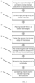
- Fig. 1 is a flow chart generally illustrating an exemplary procedure for manually pre-stretching an electro-active polymer film and holding it in a pre-stretched state, according to some embodiments of the present invention.
- this procedure can include at least the steps of:
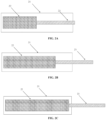
- Figs. 2A, 2B and 2C schematically illustrate an exemplary method of using a mechanical limitation for pre-stretching an electro-active polymer film by a pre-determined amount in a single axis.
- the EAP film 22 is connected to a pulling strap 23 and is held within a sleeve 21. Pulling the pulling strap 23 stretches the EAP film 22, as shown in Figs. 2B and 2C .
- Figs. 3A, 3B and 3C schematically illustrate an exemplary method of using a mechanical limitation for pre-stretching an electro-active polymer by a pre-determined amount in two axes.
- the EAP film 32 is connected to two pulling straps 33 and is held within a sleeve 31. Pulling the pulling straps 33 stretches the EAP film 32, as shown in Figs. 3B and 3C .
- Fig. 4 schematically illustrates an exemplary method of fixing a pre-stretched electro-active polymer by wrapping it around a solid body.
- the sleeve 41 is wrapped around a solid body.
- the sleeve is fixed in place by connecting the pulling straps to the sleeve.
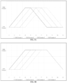
- Figs. 5A, 5B and 5C are charts which generally illustrate an exemplary procedure of applying sequential compression by 4 EAP actuators, in which the 4 EAP actuators are wrapped in parallel along the solid body and the high pressure is being applied sequentially.
- Fig. 5D is a chart which generally illustrates an exemplary procedure of applying intermittent compression applied by 4 EAP actuators, in which the 4 EAP actuators are wrapped in parallel along the solid body and the high pressure is being applied intermittently by the 4 EAP actuators.
- the present invention is directed to an exemplary inventive method that at least includes steps of: providing at least one housing having a pre-determined physical structure; fixing a first edge of at least one electro-active polymer (EAP) film within the at least one housing; connecting a first edge of at least one pulling mechanism to a second edge of the at least one EAP film; where the first edge and the second edge of the at least one EAP film are opposite of each other; where a second edge of the at least one pulling mechanism extends outside of the at least one housing; sufficiently pulling at the second edge of the at least one pulling mechanism to form at least one pre-stretched EAP film that has been stretched in a first axial direction within the at least one housing by a first pre-determined, pre-stretched amount; and where the pre-determined, pre-stretched amount is limited by the pre-determined physical structure of the housing.
- EAP electro-active polymer
- the exemplary inventive method may further include utilizing at least one first attachment mechanism to fix the first edge of the at least one EAP film to a first edge of the at least one housing; and utilizing at least one second attachment mechanism to fix the second edge of the at least one EAP film to the at least one pulling mechanism.
- the at least one first attachment mechanism and the at least one second attachment mechanism are clips.
- the at least one housing is a flexible sleeve.
- the exemplary inventive method may further include wrapping the at least one housing with the at least one pre-stretched EAP film around a solid body, and securing the at least one housing on the solid body.
- the solid body is at least a portion of a part of a human or animal body.
- the exemplary inventive method may further include securing of the flexible sleeve on the solid body by connecting the at least one second attachment mechanism to at least one of: the at least one first attachment mechanism or the at least one housing.
- the wrapping the flexible sleeve with the at least one pre-stretched EAP film around the solid body is configured to apply a particular pressure to the solid body.
- the exemplary inventive method may further include activating the at least one pre-stretched EAP film to reduce the particular pressure on the solid body to a particular reduced pressure.
- the exemplary inventive method may further include deactivating the at least one pre-stretched EAP film to raise the particular reduced pressure.
- a X number of pre-stretched EAP films are associated with one or more housings, where X is between 1 and 10,000.
- the exemplary inventive method may further include subjecting, during a particular time period, one or more first EAP films to at least one condition selected from: i) activation or ii) deactivation; and subjecting, during the particular time period, one or more second EAP films to the at least one condition; and where the subjecting the one or more first EAP films to the at least one condition and the subjecting the one or more second EAP films to the at least one condition are performed with respect to each other i) sequentially or ii) intermittently.
- the exemplary inventive method may further include connecting a first edge of at least one second pulling mechanism to a third edge of the at least one EAP film; where the first edge, the second edge, and the third edge of the at least one EAP film are distinct edges; where a second edge of the at least one second pulling mechanism extends outside of the at least one housing; sufficiently pulling at the second edge of the at least one second pulling mechanism to stretch the at least one EAP film in a second axial direction within the at least one housing by a second pre-determined, pre-stretched amount to form at least one biaxially pre-stretched EAP film; where the second pre-determined, pre-stretched amount is also limited by the pre-determined physical structure of the housing.
- the present invention is directed to an exemplary active compression device that may include at least the following components of: at least one housing having a pre-determined physical structure; at least one electro-active polymer (EAP) film having a first edge that is fixed within the at least one housing; at least one pulling mechanism that is connected to a first edge of to a second edge of the at least one EAP film; where the first edge and the second edge of the at least one EAP film are opposite of each other; where a second edge of the at least one pulling mechanism extends outside of the at least one housing; where the at least one pulling mechanism is configured to allow sufficient pulling at the second edge of the at least one pulling mechanism to form at least one pre-stretched EAP film that has been stretched in a first axial direction within the at least one housing by a first pre-determined, pre-stretched amount; and where the pre-determined, pre-stretched amount is limited by the pre-determined physical structure of the housing.
- EAP electro-active polymer
Landscapes
- Health & Medical Sciences (AREA)
- Animal Behavior & Ethology (AREA)
- Public Health (AREA)
- Epidemiology (AREA)
- Pain & Pain Management (AREA)
- Physical Education & Sports Medicine (AREA)
- Rehabilitation Therapy (AREA)
- Life Sciences & Earth Sciences (AREA)
- General Health & Medical Sciences (AREA)
- Veterinary Medicine (AREA)
- Engineering & Computer Science (AREA)
- Manufacturing & Machinery (AREA)
- Physics & Mathematics (AREA)
- Spectroscopy & Molecular Physics (AREA)
- Rheumatology (AREA)
- Orthopedic Medicine & Surgery (AREA)
- Shaping By String And By Release Of Stress In Plastics And The Like (AREA)
- Manufacture Of Macromolecular Shaped Articles (AREA)
Claims (13)
- Verfahren, welches Folgendes aufweist:- Bereitstellen mindestens eines Gehäuses (21, 31) mit einer vorbestimmten physischen Struktur;- Befestigen eines ersten Randes mindestens einer elektroaktiven Polymer (EAP)-Folie (22, 32) mittels mindestens eines ersten Befestigungsmechanismus in Form einer ersten Klammer an einem ersten Rand innerhalb des mindestens einen Gehäuses (21, 31);- Verbinden eines ersten Randes mindestens eines Zugmechanismus (23, 33) mittels mindestens eines zweiten Befestigungsmechanismus in Form einer zweiten Klammer an einem zweiten Rand der mindestens einen EAP-Folie (22, 32);wobei der erste Rand und der zweite Rand der mindestens einen EAP-Folie (22, 32) einander gegenüber liegen;wobei sich ein zweiter Rand des mindestens einen Zugmechanismus (23, 33) außerhalb des mindestens einen Gehäuses (21, 31) erstreckt; ausreichendes Ziehen an dem zweiten Rand des mindestens einen Zugmechanismus (23, 33), um mindestens eine vorgestreckte EAP-Folie (22, 32) zu bilden, die in einer ersten axialen Richtung innerhalb des mindestens einen Gehäuses (21, 31) um einen ersten vorbestimmten, vorgestreckten Betrag gestreckt wurde; undwobei der erste vorbestimmte, vorgestreckte Betrag durch die vorbestimmte physische Struktur des mindestens einen Gehäuses (21, 31) in Form einer Barriere, die die Bewegung des zweiten Clips beschränkt, begrenzt wird.
- Verfahren nach Anspruch 1,
wobei das mindestens eine Gehäuse (21, 31) eine flexible Hülse ist, und wobei das Verfahren vorzugsweise weiterhin aufweist:- Wickeln des mindestens einen Gehäuses (21, 31) mit der mindestens einen vorgestreckten EAP-Folie (22, 32) um einen festen Körper, und- Befestigen des mindestens einen Gehäuses (21, 31) an dem festen Körper, wobei der feste Körper vorzugsweise mindestens ein Bereich eines Teils eines menschlichen oder tierischen Körpers ist. - Verfahren nach Anspruch 2,
wobei das Befestigen der flexiblen Hülse an dem festen Körper folgendes aufweist:- Verbinden des mindestens einen zweiten Befestigungsmechanismus mit mindestens einem von:i) dem mindestens einen ersten Befestigungsmechanismus oderii) dem mindestens einen Gehäuse (21, 31). - Verfahren nach Anspruch 2 oder 3,wobei das Wickeln der flexiblen Hülse mit der mindestens einen vorgestreckten EAP-Folie (22, 32) um den festen Körper so konfiguriert ist, dass ein bestimmter Druck auf den festen Körper ausgeübt wird, wobei das Verfahren vorzugsweise ferner aufweist:- Aktivieren der mindestens einen vorgestreckten EAP-Folie (22, 32), um den bestimmten Druck auf den festen Körper auf einen bestimmten reduzierten Druck zu reduzieren,und wobei das Verfahren vorzugsweise weiterhin aufweist:- Deaktivieren der mindestens einen vorgestreckten EAP-Folie (22, 32), um den bestimmten reduzierten Druck zu erhöhen.
- Verfahren nach einem der Ansprüche 2 bis 4,
wobei eine Anzahl X von vorgestreckten EAP-Folien (22, 32) einem oder mehreren Gehäusen (21, 31) zugeordnet ist, wobei X zwischen 1 und 10.000 liegt. - Verfahren nach Anspruch 5,
ferner aufweisend:- Unterziehen einer oder mehrerer erster EAP-Folien (22, 32) während einer bestimmten Zeitspanne mindestens einem Zustand, der ausgewählt ist aus:i) Aktivierung oderii) Deaktivierung; und- Unterziehen einer oder mehrerer zweiter EAP-Folien (22, 32) während der bestimmten Zeitspanne dem mindestens einen Zustand; undwobei das Unterziehen der einen oder der mehreren ersten EAP-Folien (22, 32) dem mindestens einen Zustand und das Unterziehen der einen oder der mehreren zweiten EAP-Folien (22, 32) dem mindestens einen Zustand in Bezug zueinanderi) sequentiell oderii) intermittierenddurchgeführt werden. - Verfahren nach einem der Ansprüche 1 bis 6,
ferner aufweisend:- Verbinden eines ersten Randes von mindestens einem zweiten Zugmechanismus (23, 33) mit einem dritten Rand der mindestens einen EAP-Folie (22, 32);wobei der erste Rand, der zweite Rand und der dritte Rand der mindestens einen EAP-Folie (22, 32) unterschiedliche Ränder sind;wobei sich ein zweiter Rand des mindestens einen zweiten Zugmechanismus (23, 33) außerhalb des mindestens einen Gehäuses (21, 31) erstreckt; ausreichendes Ziehen an dem zweiten Rand des mindestens einen zweiten Zugmechanismus (23, 33), um die mindestens eine EAP-Folie (22, 32) in einer zweiten axialen Richtung innerhalb des mindestens einen Gehäuses (21, 31) um einen zweiten vorbestimmten, vorgestreckten Betrag zu strecken, um mindestens eine biaxial vorgestreckte EAP-Folie (22, 32) zu bilden;wobei der zweite vorbestimmte, vorgestreckte Betrag auch durch die vorbestimmte physische Struktur des Gehäuses (21, 31) begrenzt ist. - Aktive Kompressionsvorrichtung, welche Folgendes aufweist:- mindestens ein Gehäuse (21, 31) mit einer vorbestimmten physischen Struktur;- mindestens eine elektroaktive Polymer (EAP)-Folie (22, 32) mit einem ersten Rand, der mittels mindestens eines ersten Befestigungsmechanismus in Form einer ersten Klammer an einem ersten Rand innerhalb des mindestens einen Gehäuses (21, 31) befestigt ist;- mindestens einen Zugmechanismus (23, 33), der mittels mindestens eines zweiten Befestigungsmechanismus in Form einer zweiten Klammer mit einem zweiten Rand der mindestens einen EAP-Folie (22, 32) verbunden ist;wobei der erste Rand und der zweite Rand der mindestens einen EAP-Folie (22, 32) einander gegenüberliegen;wobei ein zweiter Rand des mindestens einen Zugmechanismus (23, 33) sich außerhalb des mindestens einen Gehäuses (21, 31) erstreckt;wobei der mindestens eine Zugmechanismus (23, 33) so konfiguriert ist, dass er ein ausreichendes Ziehen an dem zweiten Rand des mindestens einen Zugmechanismus (23, 33) ermöglicht, um mindestens eine vorgestreckte EAP-Folie (22, 32) zu bilden, die in einer ersten axialen Richtung innerhalb des mindestens einen Gehäuses (21, 31) um einen ersten vorbestimmten, vorgestreckten Betrag gestreckt worden ist; undwobei der erste vorbestimmte, vorgestreckte Betrag durch die vorbestimmte physische Struktur des mindestens einen Gehäuses (21, 31) in Form einer Barriere, die die Bewegung des zweiten Clips beschränkt, begrenzt wird.
- Vorrichtung nach Anspruch 8,wobei das mindestens eine Gehäuse (21, 31) eine flexible Hülse ist, undwobei das mindestens eine Gehäuse (21, 31) vorzugsweise konfiguriert ist um:- dem mindestens eine Gehäuse (21, 31) mit der mindestens einen vorgestreckten EAP-Folie (22, 32) zu ermöglichen, um einen festen Körper gewickelt zu werden, und- das mindestens eine Gehäuse (21, 31) an dem festen Körper zu befestigen,wobei der feste Körper vorzugsweise mindestens ein Bereich eines menschlichen oder tierischen Körpers ist; und/oderwobei das mindestens eine Gehäuse (21, 31) mit der mindestens einen vorgestreckten EAP-Folie (22, 32) vorzugsweise so konfiguriert ist, dass es einen bestimmten Druck auf den festen Körper ausübt.
- Vorrichtung nach Anspruch 9,
wobei die Vorrichtung ferner konfiguriert ist, um:i) den bestimmten Druck auf den festen Körper auf einen bestimmten reduzierten Druck zu reduzieren, wenn die mindestens eine vorgestreckte EAP-Folie (22, 32) aktiviert ist, undii) den bestimmten redudzierten Druck zu erhöhen, wenn die mindestens eine vorgestreckte EAP-Folie (22, 32) deaktiviert ist. - Vorrichtung nach Anspruch 9 oder 10,
wobei eine Anzahl X von vorgestreckten EAP-Folien (22, 32) einem oder mehreren Gehäusen (21, 31) zugeordnet ist, wobei X zwischen 1 und 10.000 liegt. - Vorrichtung nach Anspruch 11,wobei die Vorrichtung ferner so konfiguriert ist, dass sie es ermöglicht- während einer bestimmten Zeitspanne eine oder mehrere erste EAP-Folien (22, 32) mindestens einem Zustand zu unterziehen, der ausgewählt ist aus:i) Aktivierung oderii) Deaktivierung; und- während der bestimmten Zeitspanne eine oder mehrerer zweite EAP-Folien (22, 32) dem mindestens einen Zustand zu unterziehen; undwobei das Unterziehen der einen oder der mehreren ersten EAP-Folien (22, 32) dem mindestens einen Zustand und das Unterziehen der einen oder der mehreren zweiten EAP-Folien (22, 32) dem mindestens einen Zustand in Bezug zueinanderi) sequentiell oderii) intermittierenddurchgeführt werden.
- Vorrichtung nach einem der Ansprüche 8 bis 12,
ferner aufweisend:- mindestens einen zweiten Zugmechanismus (23, 33), der an einem ersten Rand des mindestens einen zweiten Zugmechanismus (23, 33) mit einem dritten Rand der mindestens einen EAP-Folie (22, 32) verbunden ist;wobei der erste Rand, der zweite Rand und der dritte Rand der mindestens einen EAP-Folie (22, 32) unterschiedliche Ränder sind;wobei ein zweiter Rand des mindestens einen zweiten Zugmechanismus (23, 33) sich außerhalb des mindestens einen Gehäuses (21, 31) erstreckt;wobei der mindestens eine zweite Zugmechanismus (23, 33) so konfiguriert ist, dass er ein ausreichendes Ziehen an dem zweiten Rand des mindestens einen zweiten Zugmechanismus (23, 33) ermöglicht, um die mindestens eine EAP-Folie (22, 32) in einer zweiten axialen Richtung innerhalb des mindestens einen Gehäuses (21, 31) um einen zweiten vorbestimmten, vorgestreckten Betrag zu strecken, um mindestens eine biaxial vorgestreckte EAP-Folie (22, 32) zu bilden;wobei der zweite vorbestimmte, vorgestreckte Betrag auch durch die vorbestimmte physische Struktur des Gehäuses (21, 31) begrenzt ist.
Applications Claiming Priority (2)
| Application Number | Priority Date | Filing Date | Title |
|---|---|---|---|
| US201762540014P | 2017-08-01 | 2017-08-01 | |
| PCT/IB2018/000957 WO2019025854A2 (en) | 2017-08-01 | 2018-07-25 | MECHANISMS FOR PRE-STRIPPING ELECTRO-ACTIVE POLYMERS ACCORDING TO A PREDETERMINED QUANTITY AND METHODS OF USE THEREOF |
Publications (3)
| Publication Number | Publication Date |
|---|---|
| EP3661470A2 EP3661470A2 (de) | 2020-06-10 |
| EP3661470A4 EP3661470A4 (de) | 2021-05-12 |
| EP3661470B1 true EP3661470B1 (de) | 2023-10-11 |
Family
ID=65229862
Family Applications (1)
| Application Number | Title | Priority Date | Filing Date |
|---|---|---|---|
| EP18840564.1A Active EP3661470B1 (de) | 2017-08-01 | 2018-07-25 | Mechanismen zum vorstrecken elektroaktiver polymere um ein vorbestimmtes ausmass und verwendungsverfahren dafür |
Country Status (3)
| Country | Link |
|---|---|
| US (4) | US11223006B2 (de) |
| EP (1) | EP3661470B1 (de) |
| WO (1) | WO2019025854A2 (de) |
Families Citing this family (4)
| Publication number | Priority date | Publication date | Assignee | Title |
|---|---|---|---|---|
| WO2019102417A1 (en) * | 2017-11-27 | 2019-05-31 | Ecole Polytechnique Federale De Lausanne (Epfl) | Spring with a plurality of elements, and actuator including such a spring |
| US11903323B2 (en) | 2018-05-02 | 2024-02-13 | ElastiMed Ltd. | Strap having a portion of electro-active polymer, methods and mechanisms for making and using the same |
| CN115466474A (zh) * | 2021-06-10 | 2022-12-13 | 香港理工大学 | 湿气发电材料及装置 |
| CN113576420B (zh) * | 2021-09-01 | 2024-09-27 | 青岛市胶州中心医院 | 一种神经内科触觉感知装置 |
Family Cites Families (17)
| Publication number | Priority date | Publication date | Assignee | Title |
|---|---|---|---|---|
| AU2001268027A1 (en) * | 2000-02-23 | 2001-09-12 | Sri International | Biologically powered electroactive polymer generators |
| AU2001238675A1 (en) * | 2000-02-23 | 2001-09-03 | Sri International | Electroactive polymer thermal electric generators |
| US8181338B2 (en) * | 2000-11-02 | 2012-05-22 | Danfoss A/S | Method of making a multilayer composite |
| WO2003081762A1 (en) * | 2002-03-18 | 2003-10-02 | Sri International | Electroactive polymer devices for moving fluid |
| ES2309502T3 (es) * | 2003-02-24 | 2008-12-16 | Danfoss A/S | Vendaje de compresion elastico electroactivo. |
| AU2004316255B2 (en) * | 2003-08-29 | 2009-12-03 | Sri International | Electroactive polymer pre-strain |
| US8383226B2 (en) * | 2004-03-12 | 2013-02-26 | University Of Maryland | Structures and methods for increasing the speed of electroactive polymers |
| ATE397912T1 (de) * | 2004-10-11 | 2008-07-15 | Smm Medical Ab | Elektroaktive kompressionsbandage |
| WO2006121818A2 (en) * | 2005-05-05 | 2006-11-16 | Rodrigo Alvarez Icaza Rivera | Dielectric elastomer fiber transducers |
| BRPI0621229A2 (pt) * | 2006-01-13 | 2011-12-06 | Smm Medical Ab | dispositivo e sistema para tratamento por compressão de uma parte do corpo |
| KR100772908B1 (ko) * | 2006-05-15 | 2007-11-05 | 삼성전자주식회사 | 근육 운동 보조 장치 |
| EP1881024A1 (de) * | 2006-07-18 | 2008-01-23 | Nederlandse Organisatie voor toegepast- natuurwetenschappelijk onderzoek TNO | Verwendung eines Weichmachers in einer elektroaktiven Polymerzusammensetzung |
| US7992217B2 (en) * | 2009-04-30 | 2011-08-09 | The Invention Science Fund I, Llc | Shape changing material |
| TW201403899A (zh) * | 2012-04-12 | 2014-01-16 | Bayer Materialscience Ag | 具有改良性能之eap傳感器 |
| EP4284149A3 (de) * | 2014-12-29 | 2024-03-06 | Elastimed Ltd. | Verfahren und mechanismen zur aufrechterhaltung eines elektroaktiven polymers in einem vorstreckzustand und verwendungen davon |
| US10758160B2 (en) * | 2017-01-20 | 2020-09-01 | Figur8, Inc. | Body part motion analysis with wearable sensors |
| SI25884A (sl) * | 2019-09-11 | 2021-03-31 | MESI d.o.o. | Cevasto kompresijsko oblačilo za spremljanje terapije in fizioloških aktivnostih osebe |
-
2018
- 2018-07-25 EP EP18840564.1A patent/EP3661470B1/de active Active
- 2018-07-25 US US16/045,106 patent/US11223006B2/en active Active
- 2018-07-25 WO PCT/IB2018/000957 patent/WO2019025854A2/en not_active Ceased
-
2022
- 2022-01-10 US US17/572,255 patent/US20220246829A1/en not_active Abandoned
-
2023
- 2023-05-19 US US18/320,474 patent/US20230371389A1/en not_active Abandoned
-
2024
- 2024-08-21 US US18/811,522 patent/US20240415021A1/en not_active Abandoned
Also Published As
| Publication number | Publication date |
|---|---|
| EP3661470A2 (de) | 2020-06-10 |
| WO2019025854A3 (en) | 2019-03-21 |
| US20240415021A1 (en) | 2024-12-12 |
| US20230371389A1 (en) | 2023-11-16 |
| US11223006B2 (en) | 2022-01-11 |
| EP3661470A4 (de) | 2021-05-12 |
| US20190044052A1 (en) | 2019-02-07 |
| WO2019025854A2 (en) | 2019-02-07 |
| CA3071774A1 (en) | 2019-02-07 |
| US20220246829A1 (en) | 2022-08-04 |
Similar Documents
| Publication | Publication Date | Title |
|---|---|---|
| US20240415021A1 (en) | Compositions for active compression devices and related methods | |
| US20240130047A1 (en) | Methods and mechanisms for maintaining an electro-active polymer in a pre-stretch state and uses thereof | |
| US20240365672A1 (en) | Strap having a portion of electro-active polymer, methods and mechanisms for making and using the same | |
| JPWO2007023625A1 (ja) | 高分子アクチュエータ | |
| JP6939819B2 (ja) | 触感提示装置 | |
| CN110603727B (zh) | 致动器、驱动构件、触觉提示装置和驱动装置 | |
| CA3071774C (en) | Mechanisms for pre-stretching electro-active polymers by a pre-determined amount and methods of use thereof | |
| US11684753B2 (en) | Invasive medical device and manufacturing methods | |
| Chiba et al. | Examination of factors to improve the performance of dielectric elastomer transducers and their applications | |
| US11097436B2 (en) | Friction control device and method | |
| US20250325408A1 (en) | Methods and mechanisms for maintaining an electro-active polymer in a pre-stretch state and uses thereof | |
| US20160260888A1 (en) | Dielectric elastomer actautor | |
| US11278455B2 (en) | Methods for maintaining an electro-active polymer in a pre-stretch state | |
| US20220416689A1 (en) | Method of using a hydroelectric actuator to create a controllable pressure on a cylindrically shaped object | |
| KR102135089B1 (ko) | 전기 활성 섬유 | |
| US20230292619A1 (en) | An actuator mechanism | |
| Su et al. | Membrane Tension Control |
Legal Events
| Date | Code | Title | Description |
|---|---|---|---|
| STAA | Information on the status of an ep patent application or granted ep patent |
Free format text: STATUS: THE INTERNATIONAL PUBLICATION HAS BEEN MADE |
|
| PUAI | Public reference made under article 153(3) epc to a published international application that has entered the european phase |
Free format text: ORIGINAL CODE: 0009012 |
|
| STAA | Information on the status of an ep patent application or granted ep patent |
Free format text: STATUS: REQUEST FOR EXAMINATION WAS MADE |
|
| 17P | Request for examination filed |
Effective date: 20200207 |
|
| AK | Designated contracting states |
Kind code of ref document: A2 Designated state(s): AL AT BE BG CH CY CZ DE DK EE ES FI FR GB GR HR HU IE IS IT LI LT LU LV MC MK MT NL NO PL PT RO RS SE SI SK SM TR |
|
| AX | Request for extension of the european patent |
Extension state: BA ME |
|
| DAV | Request for validation of the european patent (deleted) | ||
| DAX | Request for extension of the european patent (deleted) | ||
| REG | Reference to a national code |
Ref country code: DE Ref legal event code: R079 Free format text: PREVIOUS MAIN CLASS: A61F0013060000 Ipc: H01L0041193000 Ref document number: 602018059302 Country of ref document: DE |
|
| A4 | Supplementary search report drawn up and despatched |
Effective date: 20210414 |
|
| RIC1 | Information provided on ipc code assigned before grant |
Ipc: H01L 41/193 20060101AFI20210408BHEP Ipc: H01L 41/253 20130101ALI20210408BHEP Ipc: A61H 23/02 20060101ALI20210408BHEP Ipc: A61H 11/00 20060101ALN20210408BHEP |
|
| REG | Reference to a national code |
Ref country code: DE Ref legal event code: R079 Free format text: PREVIOUS MAIN CLASS: H01L0041193000 Ipc: A61H0023020000 Ref document number: 602018059302 Country of ref document: DE |
|
| GRAP | Despatch of communication of intention to grant a patent |
Free format text: ORIGINAL CODE: EPIDOSNIGR1 |
|
| STAA | Information on the status of an ep patent application or granted ep patent |
Free format text: STATUS: GRANT OF PATENT IS INTENDED |
|
| RIC1 | Information provided on ipc code assigned before grant |
Ipc: A61H 11/00 20060101ALN20230324BHEP Ipc: H10N 30/88 20230101ALI20230324BHEP Ipc: H10N 30/857 20230101ALI20230324BHEP Ipc: H10N 30/04 20230101ALI20230324BHEP Ipc: A61H 1/00 20060101ALI20230324BHEP Ipc: A61H 23/02 20060101AFI20230324BHEP |
|
| INTG | Intention to grant announced |
Effective date: 20230425 |
|
| GRAS | Grant fee paid |
Free format text: ORIGINAL CODE: EPIDOSNIGR3 |
|
| GRAA | (expected) grant |
Free format text: ORIGINAL CODE: 0009210 |
|
| STAA | Information on the status of an ep patent application or granted ep patent |
Free format text: STATUS: THE PATENT HAS BEEN GRANTED |
|
| AK | Designated contracting states |
Kind code of ref document: B1 Designated state(s): AL AT BE BG CH CY CZ DE DK EE ES FI FR GB GR HR HU IE IS IT LI LT LU LV MC MK MT NL NO PL PT RO RS SE SI SK SM TR |
|
| REG | Reference to a national code |
Ref country code: GB Ref legal event code: FG4D |
|
| REG | Reference to a national code |
Ref country code: CH Ref legal event code: EP |
|
| REG | Reference to a national code |
Ref country code: DE Ref legal event code: R096 Ref document number: 602018059302 Country of ref document: DE |
|
| REG | Reference to a national code |
Ref country code: IE Ref legal event code: FG4D |
|
| REG | Reference to a national code |
Ref country code: LT Ref legal event code: MG9D |
|
| REG | Reference to a national code |
Ref country code: NL Ref legal event code: MP Effective date: 20231011 |
|
| REG | Reference to a national code |
Ref country code: AT Ref legal event code: MK05 Ref document number: 1619517 Country of ref document: AT Kind code of ref document: T Effective date: 20231011 |
|
| PG25 | Lapsed in a contracting state [announced via postgrant information from national office to epo] |
Ref country code: NL Free format text: LAPSE BECAUSE OF FAILURE TO SUBMIT A TRANSLATION OF THE DESCRIPTION OR TO PAY THE FEE WITHIN THE PRESCRIBED TIME-LIMIT Effective date: 20231011 |
|
| PG25 | Lapsed in a contracting state [announced via postgrant information from national office to epo] |
Ref country code: GR Free format text: LAPSE BECAUSE OF FAILURE TO SUBMIT A TRANSLATION OF THE DESCRIPTION OR TO PAY THE FEE WITHIN THE PRESCRIBED TIME-LIMIT Effective date: 20240112 |
|
| PG25 | Lapsed in a contracting state [announced via postgrant information from national office to epo] |
Ref country code: IS Free format text: LAPSE BECAUSE OF FAILURE TO SUBMIT A TRANSLATION OF THE DESCRIPTION OR TO PAY THE FEE WITHIN THE PRESCRIBED TIME-LIMIT Effective date: 20240211 |
|
| PG25 | Lapsed in a contracting state [announced via postgrant information from national office to epo] |
Ref country code: LT Free format text: LAPSE BECAUSE OF FAILURE TO SUBMIT A TRANSLATION OF THE DESCRIPTION OR TO PAY THE FEE WITHIN THE PRESCRIBED TIME-LIMIT Effective date: 20231011 |
|
| PG25 | Lapsed in a contracting state [announced via postgrant information from national office to epo] |
Ref country code: AT Free format text: LAPSE BECAUSE OF FAILURE TO SUBMIT A TRANSLATION OF THE DESCRIPTION OR TO PAY THE FEE WITHIN THE PRESCRIBED TIME-LIMIT Effective date: 20231011 |
|
| PG25 | Lapsed in a contracting state [announced via postgrant information from national office to epo] |
Ref country code: ES Free format text: LAPSE BECAUSE OF FAILURE TO SUBMIT A TRANSLATION OF THE DESCRIPTION OR TO PAY THE FEE WITHIN THE PRESCRIBED TIME-LIMIT Effective date: 20231011 |
|
| PG25 | Lapsed in a contracting state [announced via postgrant information from national office to epo] |
Ref country code: LT Free format text: LAPSE BECAUSE OF FAILURE TO SUBMIT A TRANSLATION OF THE DESCRIPTION OR TO PAY THE FEE WITHIN THE PRESCRIBED TIME-LIMIT Effective date: 20231011 Ref country code: IS Free format text: LAPSE BECAUSE OF FAILURE TO SUBMIT A TRANSLATION OF THE DESCRIPTION OR TO PAY THE FEE WITHIN THE PRESCRIBED TIME-LIMIT Effective date: 20240211 Ref country code: GR Free format text: LAPSE BECAUSE OF FAILURE TO SUBMIT A TRANSLATION OF THE DESCRIPTION OR TO PAY THE FEE WITHIN THE PRESCRIBED TIME-LIMIT Effective date: 20240112 Ref country code: ES Free format text: LAPSE BECAUSE OF FAILURE TO SUBMIT A TRANSLATION OF THE DESCRIPTION OR TO PAY THE FEE WITHIN THE PRESCRIBED TIME-LIMIT Effective date: 20231011 Ref country code: BG Free format text: LAPSE BECAUSE OF FAILURE TO SUBMIT A TRANSLATION OF THE DESCRIPTION OR TO PAY THE FEE WITHIN THE PRESCRIBED TIME-LIMIT Effective date: 20240111 Ref country code: AT Free format text: LAPSE BECAUSE OF FAILURE TO SUBMIT A TRANSLATION OF THE DESCRIPTION OR TO PAY THE FEE WITHIN THE PRESCRIBED TIME-LIMIT Effective date: 20231011 Ref country code: PT Free format text: LAPSE BECAUSE OF FAILURE TO SUBMIT A TRANSLATION OF THE DESCRIPTION OR TO PAY THE FEE WITHIN THE PRESCRIBED TIME-LIMIT Effective date: 20240212 |
|
| PG25 | Lapsed in a contracting state [announced via postgrant information from national office to epo] |
Ref country code: SE Free format text: LAPSE BECAUSE OF FAILURE TO SUBMIT A TRANSLATION OF THE DESCRIPTION OR TO PAY THE FEE WITHIN THE PRESCRIBED TIME-LIMIT Effective date: 20231011 Ref country code: RS Free format text: LAPSE BECAUSE OF FAILURE TO SUBMIT A TRANSLATION OF THE DESCRIPTION OR TO PAY THE FEE WITHIN THE PRESCRIBED TIME-LIMIT Effective date: 20231011 Ref country code: PL Free format text: LAPSE BECAUSE OF FAILURE TO SUBMIT A TRANSLATION OF THE DESCRIPTION OR TO PAY THE FEE WITHIN THE PRESCRIBED TIME-LIMIT Effective date: 20231011 Ref country code: NO Free format text: LAPSE BECAUSE OF FAILURE TO SUBMIT A TRANSLATION OF THE DESCRIPTION OR TO PAY THE FEE WITHIN THE PRESCRIBED TIME-LIMIT Effective date: 20240111 Ref country code: LV Free format text: LAPSE BECAUSE OF FAILURE TO SUBMIT A TRANSLATION OF THE DESCRIPTION OR TO PAY THE FEE WITHIN THE PRESCRIBED TIME-LIMIT Effective date: 20231011 Ref country code: HR Free format text: LAPSE BECAUSE OF FAILURE TO SUBMIT A TRANSLATION OF THE DESCRIPTION OR TO PAY THE FEE WITHIN THE PRESCRIBED TIME-LIMIT Effective date: 20231011 |
|
| PG25 | Lapsed in a contracting state [announced via postgrant information from national office to epo] |
Ref country code: DK Free format text: LAPSE BECAUSE OF FAILURE TO SUBMIT A TRANSLATION OF THE DESCRIPTION OR TO PAY THE FEE WITHIN THE PRESCRIBED TIME-LIMIT Effective date: 20231011 |
|
| REG | Reference to a national code |
Ref country code: DE Ref legal event code: R097 Ref document number: 602018059302 Country of ref document: DE |
|
| PG25 | Lapsed in a contracting state [announced via postgrant information from national office to epo] |
Ref country code: CZ Free format text: LAPSE BECAUSE OF FAILURE TO SUBMIT A TRANSLATION OF THE DESCRIPTION OR TO PAY THE FEE WITHIN THE PRESCRIBED TIME-LIMIT Effective date: 20231011 |
|
| PG25 | Lapsed in a contracting state [announced via postgrant information from national office to epo] |
Ref country code: SK Free format text: LAPSE BECAUSE OF FAILURE TO SUBMIT A TRANSLATION OF THE DESCRIPTION OR TO PAY THE FEE WITHIN THE PRESCRIBED TIME-LIMIT Effective date: 20231011 |
|
| PG25 | Lapsed in a contracting state [announced via postgrant information from national office to epo] |
Ref country code: SM Free format text: LAPSE BECAUSE OF FAILURE TO SUBMIT A TRANSLATION OF THE DESCRIPTION OR TO PAY THE FEE WITHIN THE PRESCRIBED TIME-LIMIT Effective date: 20231011 Ref country code: SK Free format text: LAPSE BECAUSE OF FAILURE TO SUBMIT A TRANSLATION OF THE DESCRIPTION OR TO PAY THE FEE WITHIN THE PRESCRIBED TIME-LIMIT Effective date: 20231011 Ref country code: RO Free format text: LAPSE BECAUSE OF FAILURE TO SUBMIT A TRANSLATION OF THE DESCRIPTION OR TO PAY THE FEE WITHIN THE PRESCRIBED TIME-LIMIT Effective date: 20231011 Ref country code: IT Free format text: LAPSE BECAUSE OF FAILURE TO SUBMIT A TRANSLATION OF THE DESCRIPTION OR TO PAY THE FEE WITHIN THE PRESCRIBED TIME-LIMIT Effective date: 20231011 Ref country code: EE Free format text: LAPSE BECAUSE OF FAILURE TO SUBMIT A TRANSLATION OF THE DESCRIPTION OR TO PAY THE FEE WITHIN THE PRESCRIBED TIME-LIMIT Effective date: 20231011 Ref country code: DK Free format text: LAPSE BECAUSE OF FAILURE TO SUBMIT A TRANSLATION OF THE DESCRIPTION OR TO PAY THE FEE WITHIN THE PRESCRIBED TIME-LIMIT Effective date: 20231011 Ref country code: CZ Free format text: LAPSE BECAUSE OF FAILURE TO SUBMIT A TRANSLATION OF THE DESCRIPTION OR TO PAY THE FEE WITHIN THE PRESCRIBED TIME-LIMIT Effective date: 20231011 |
|
| PLBE | No opposition filed within time limit |
Free format text: ORIGINAL CODE: 0009261 |
|
| STAA | Information on the status of an ep patent application or granted ep patent |
Free format text: STATUS: NO OPPOSITION FILED WITHIN TIME LIMIT |
|
| 26N | No opposition filed |
Effective date: 20240712 |
|
| PG25 | Lapsed in a contracting state [announced via postgrant information from national office to epo] |
Ref country code: SI Free format text: LAPSE BECAUSE OF FAILURE TO SUBMIT A TRANSLATION OF THE DESCRIPTION OR TO PAY THE FEE WITHIN THE PRESCRIBED TIME-LIMIT Effective date: 20231011 |
|
| PG25 | Lapsed in a contracting state [announced via postgrant information from national office to epo] |
Ref country code: SI Free format text: LAPSE BECAUSE OF FAILURE TO SUBMIT A TRANSLATION OF THE DESCRIPTION OR TO PAY THE FEE WITHIN THE PRESCRIBED TIME-LIMIT Effective date: 20231011 |
|
| PG25 | Lapsed in a contracting state [announced via postgrant information from national office to epo] |
Ref country code: MC Free format text: LAPSE BECAUSE OF FAILURE TO SUBMIT A TRANSLATION OF THE DESCRIPTION OR TO PAY THE FEE WITHIN THE PRESCRIBED TIME-LIMIT Effective date: 20231011 |
|
| REG | Reference to a national code |
Ref country code: CH Ref legal event code: PL |
|
| PG25 | Lapsed in a contracting state [announced via postgrant information from national office to epo] |
Ref country code: LU Free format text: LAPSE BECAUSE OF NON-PAYMENT OF DUE FEES Effective date: 20240725 |
|
| GBPC | Gb: european patent ceased through non-payment of renewal fee |
Effective date: 20240725 |
|
| PG25 | Lapsed in a contracting state [announced via postgrant information from national office to epo] |
Ref country code: LU Free format text: LAPSE BECAUSE OF NON-PAYMENT OF DUE FEES Effective date: 20240725 |
|
| PG25 | Lapsed in a contracting state [announced via postgrant information from national office to epo] |
Ref country code: CH Free format text: LAPSE BECAUSE OF NON-PAYMENT OF DUE FEES Effective date: 20240731 Ref country code: BE Free format text: LAPSE BECAUSE OF NON-PAYMENT OF DUE FEES Effective date: 20240731 |
|
| PG25 | Lapsed in a contracting state [announced via postgrant information from national office to epo] |
Ref country code: GB Free format text: LAPSE BECAUSE OF NON-PAYMENT OF DUE FEES Effective date: 20240725 |
|
| REG | Reference to a national code |
Ref country code: BE Ref legal event code: MM Effective date: 20240731 |
|
| PG25 | Lapsed in a contracting state [announced via postgrant information from national office to epo] |
Ref country code: IE Free format text: LAPSE BECAUSE OF NON-PAYMENT OF DUE FEES Effective date: 20240725 |
|
| PG25 | Lapsed in a contracting state [announced via postgrant information from national office to epo] |
Ref country code: FI Free format text: LAPSE BECAUSE OF FAILURE TO SUBMIT A TRANSLATION OF THE DESCRIPTION OR TO PAY THE FEE WITHIN THE PRESCRIBED TIME-LIMIT Effective date: 20231011 |
|
| PGFP | Annual fee paid to national office [announced via postgrant information from national office to epo] |
Ref country code: DE Payment date: 20250722 Year of fee payment: 8 |
|
| PGFP | Annual fee paid to national office [announced via postgrant information from national office to epo] |
Ref country code: FR Payment date: 20250725 Year of fee payment: 8 |
|
| PG25 | Lapsed in a contracting state [announced via postgrant information from national office to epo] |
Ref country code: CY Free format text: LAPSE BECAUSE OF FAILURE TO SUBMIT A TRANSLATION OF THE DESCRIPTION OR TO PAY THE FEE WITHIN THE PRESCRIBED TIME-LIMIT; INVALID AB INITIO Effective date: 20180725 |
|
| PG25 | Lapsed in a contracting state [announced via postgrant information from national office to epo] |
Ref country code: HU Free format text: LAPSE BECAUSE OF FAILURE TO SUBMIT A TRANSLATION OF THE DESCRIPTION OR TO PAY THE FEE WITHIN THE PRESCRIBED TIME-LIMIT; INVALID AB INITIO Effective date: 20180725 |
|
| PG25 | Lapsed in a contracting state [announced via postgrant information from national office to epo] |
Ref country code: TR Free format text: LAPSE BECAUSE OF FAILURE TO SUBMIT A TRANSLATION OF THE DESCRIPTION OR TO PAY THE FEE WITHIN THE PRESCRIBED TIME-LIMIT Effective date: 20231011 |