EP3661609B1 - Vanne d'installation d'extinction d'incendie, en particulier vanne d'alarme humide, d'alarme sèche ou d'eau de pulvérisation ainsi que module de commande pour celle-ci et installation d'extinction d'incendie équipée de celle-ci - Google Patents
Vanne d'installation d'extinction d'incendie, en particulier vanne d'alarme humide, d'alarme sèche ou d'eau de pulvérisation ainsi que module de commande pour celle-ci et installation d'extinction d'incendie équipée de celle-ci Download PDFInfo
- Publication number
- EP3661609B1 EP3661609B1 EP18762226.1A EP18762226A EP3661609B1 EP 3661609 B1 EP3661609 B1 EP 3661609B1 EP 18762226 A EP18762226 A EP 18762226A EP 3661609 B1 EP3661609 B1 EP 3661609B1
- Authority
- EP
- European Patent Office
- Prior art keywords
- fire extinguishing
- extinguishing system
- fluid
- alarm
- valve
- Prior art date
- Legal status (The legal status is an assumption and is not a legal conclusion. Google has not performed a legal analysis and makes no representation as to the accuracy of the status listed.)
- Active
Links
Images
Classifications
-
- A—HUMAN NECESSITIES
- A62—LIFE-SAVING; FIRE-FIGHTING
- A62C—FIRE-FIGHTING
- A62C35/00—Permanently-installed equipment
- A62C35/58—Pipe-line systems
- A62C35/68—Details, e.g. of pipes or valve systems
-
- A—HUMAN NECESSITIES
- A62—LIFE-SAVING; FIRE-FIGHTING
- A62C—FIRE-FIGHTING
- A62C37/00—Control of fire-fighting equipment
- A62C37/50—Testing or indicating devices for determining the state of readiness of the equipment
-
- F—MECHANICAL ENGINEERING; LIGHTING; HEATING; WEAPONS; BLASTING
- F16—ENGINEERING ELEMENTS AND UNITS; GENERAL MEASURES FOR PRODUCING AND MAINTAINING EFFECTIVE FUNCTIONING OF MACHINES OR INSTALLATIONS; THERMAL INSULATION IN GENERAL
- F16K—VALVES; TAPS; COCKS; ACTUATING-FLOATS; DEVICES FOR VENTING OR AERATING
- F16K27/00—Construction of housing; Use of materials therefor
- F16K27/06—Construction of housing; Use of materials therefor of taps or cocks
- F16K27/067—Construction of housing; Use of materials therefor of taps or cocks with spherical plugs
-
- F—MECHANICAL ENGINEERING; LIGHTING; HEATING; WEAPONS; BLASTING
- F16—ENGINEERING ELEMENTS AND UNITS; GENERAL MEASURES FOR PRODUCING AND MAINTAINING EFFECTIVE FUNCTIONING OF MACHINES OR INSTALLATIONS; THERMAL INSULATION IN GENERAL
- F16K—VALVES; TAPS; COCKS; ACTUATING-FLOATS; DEVICES FOR VENTING OR AERATING
- F16K37/00—Special means in or on valves or other cut-off apparatus for indicating or recording operation thereof, or for enabling an alarm to be given
- F16K37/0025—Electrical or magnetic means
- F16K37/005—Electrical or magnetic means for measuring fluid parameters
-
- F—MECHANICAL ENGINEERING; LIGHTING; HEATING; WEAPONS; BLASTING
- F16—ENGINEERING ELEMENTS AND UNITS; GENERAL MEASURES FOR PRODUCING AND MAINTAINING EFFECTIVE FUNCTIONING OF MACHINES OR INSTALLATIONS; THERMAL INSULATION IN GENERAL
- F16K—VALVES; TAPS; COCKS; ACTUATING-FLOATS; DEVICES FOR VENTING OR AERATING
- F16K5/00—Plug valves; Taps or cocks comprising only cut-off apparatus having at least one of the sealing faces shaped as a more or less complete surface of a solid of revolution, the opening and closing movement being predominantly rotary
- F16K5/06—Plug valves; Taps or cocks comprising only cut-off apparatus having at least one of the sealing faces shaped as a more or less complete surface of a solid of revolution, the opening and closing movement being predominantly rotary with plugs having spherical surfaces; Packings therefor
- F16K5/0605—Plug valves; Taps or cocks comprising only cut-off apparatus having at least one of the sealing faces shaped as a more or less complete surface of a solid of revolution, the opening and closing movement being predominantly rotary with plugs having spherical surfaces; Packings therefor with particular plug arrangements, e.g. particular shape or built-in means
-
- A—HUMAN NECESSITIES
- A62—LIFE-SAVING; FIRE-FIGHTING
- A62C—FIRE-FIGHTING
- A62C31/00—Delivery of fire-extinguishing material
- A62C31/02—Nozzles specially adapted for fire-extinguishing
-
- A—HUMAN NECESSITIES
- A62—LIFE-SAVING; FIRE-FIGHTING
- A62C—FIRE-FIGHTING
- A62C35/00—Permanently-installed equipment
- A62C35/58—Pipe-line systems
- A62C35/62—Pipe-line systems dry, i.e. empty of extinguishing material when not in use
-
- F—MECHANICAL ENGINEERING; LIGHTING; HEATING; WEAPONS; BLASTING
- F16—ENGINEERING ELEMENTS AND UNITS; GENERAL MEASURES FOR PRODUCING AND MAINTAINING EFFECTIVE FUNCTIONING OF MACHINES OR INSTALLATIONS; THERMAL INSULATION IN GENERAL
- F16K—VALVES; TAPS; COCKS; ACTUATING-FLOATS; DEVICES FOR VENTING OR AERATING
- F16K37/00—Special means in or on valves or other cut-off apparatus for indicating or recording operation thereof, or for enabling an alarm to be given
- F16K37/0066—Hydraulic or pneumatic means
Definitions
- the valve itself usually triggers an alarm in response to the detection of the opening state, for example by means of a pressure switch arranged in an external alarm line, via which an alarm device such as an electrically operated alarm horn is then controlled, and/or directly by controlling the flow of extinguishing agent to a hydraulically operated alarm device connected to the alarm valve, such as a water-operated alarm bell.
- an alarm device such as an electrically operated alarm horn is then controlled, and/or directly by controlling the flow of extinguishing agent to a hydraulically operated alarm device connected to the alarm valve, such as a water-operated alarm bell.
- EN 10 2007 049 588 A1 For example, an electrically controlled quick vent for a dry pipe network with sprinklers is known.
- the quick vent consists of pipes, sprinklers, dry alarm valve, water supply, pressure pipe network, fittings and vent valve, whereby a solenoid valve is arranged on the dry pipe network with sprinklers and dry alarm valve, which is triggered by a control center and a pressure switch.
- a solenoid valve is arranged on the dry pipe network with sprinklers and dry alarm valve, which is triggered by a control center and a pressure switch.
- optical displays are arranged in the area of the alarm valves in order to be able to better distinguish which of the alarm valves has been opened when there are many alarm valves arranged in parallel.
- An active alarm valve is a valve that, after receiving a corresponding signal from external fire detection devices or as a function of external control interventions, actively releases a fluid flow from the fluid inlet chamber to the fluid outlet chamber by opening the closing body and triggers an alarm.
- Both of the aforementioned valve types have in common that the alarm valves are often installed in fire extinguishing systems for long periods of time without having to be used and it must be ensured that these valves function reliably in an emergency.
- the invention is based on the finding that an integration of the dedicated drain channel connected to the fluid outlet side into the housing of the fire extinguishing system valve, despite a supposed increase in the component complexity of the housing, is surprisingly offset by a significant simplification of the entire design and equipment effort for realizing a direct drain function or alarm sample function from the pipeline connected to the fire extinguishing system valve on the outlet side.
- the housing has a housing base body in which the fluid inlet chamber and the fluid outlet chamber are formed and the closing body is arranged, wherein the control module is reversibly detachably connected to the housing base body, wherein the dedicated drain channel is formed in the control module.
- a shut-off device is arranged in the dedicated drain channel, which can be switched either into the shut-off position or into the drain position.
- the fire extinguishing system valve in addition to the dedicated drain channel, has a further drain channel that is fluidically connected to the fluid outlet chamber, integrated into the housing and leading out of the housing, wherein one of the drain channels is designed as an alarm sample channel and has a cross section that is at least partially smaller than the smallest cross section of the other drain channel.
- this second drain channel is also designed in the control module.
- the second drain channel or alarm sample channel can also be selectively blocked or released by means of a shut-off device.
- the shut-off device can preferably also be switched to the alarm test position, in which the discharge channel is opened in the direction of its outlet with the cross-section reduced relative to the discharge position.
- the drain channel is provided on the inlet side with a first and a second branch channel, each of which is connected to the fluid outlet chamber in a fluid-conducting manner, wherein in the drain position of the shut-off device at least the first branch channel and the outlet of the drain channel communicate with each other in a fluid-conducting manner, in the alarm test position of the shut-off device only the second branch channel communicates with the outlet of the drain channel in a fluid-conducting manner, and in the blocking position of the shut-off device neither the first nor the second branch channel communicates with the outlet of the drain channel.
- the advantage of a single drain channel with a first and a second branch channel on the inlet side is the further reduction in the installation space required.
- an additional blocking device is arranged in the second branch channel, with which an alarm test can be triggered in the alarm test position.
- the blocking device in the discharge channel preferably has a spherical valve body, which has a first passage, which extends completely through the valve body and a second passage which is aligned at an angle to the first passage and preferably opens into the first passage.
- the cross-sectional reduction is preferably formed in the discharge channel and/or in the shut-off device.
- a bypass channel is formed in the housing, in particular in the control module, which connects the fluid inlet chamber and the fluid outlet chamber to one another in a fluid-conducting manner, wherein a shut-off device for selectively blocking or releasing the bypass channel is preferably provided in the bypass channel.
- a direct alarm channel is provided in the housing, in particular in the control module, which is directly connected to the fluid inlet chamber on the inlet side in a fluid-conducting manner and has an outlet leading out of the housing, in particular the control module, which is designed for connection to an external alarm line, in particular an alarm bell line, wherein a shut-off device is preferably arranged in the direct alarm channel, which can be switched to either a blocking position or a release position. In the blocking position of the shut-off device on the direct alarm channel, the direct alarm channel is closed. In the release position, the fluid inlet chamber is connected to the direct alarm channel outlet in a fluid-conducting manner.
- the direct alarm channel makes it possible to trigger a direct alarm without external equipment on the fire extinguishing system valve or the valve station, which, as already explained at the beginning, means triggering the alarm device without first opening the closing body of the fire extinguishing system valve.
- an alarm channel is arranged in the housing, preferably in the housing base body and/or the control module, wherein the alarm channel is arranged and designed in such a way that it is also blocked when the closing body is in the blocked state, namely particularly preferably by the closing body itself, and is flooded when the closing body is open, wherein the alarm channel extends through the housing, in particular through the control module. and has an outlet leading out of the housing, in particular the control module, which is adapted for connection to an external alarm line, in particular an alarm bell line.
- the invention also relates to a control module for a fire extinguishing system valve, in particular a wet alarm, dry alarm or spray water valve.
- the invention solves the problem underlying it, as stated at the outset, by providing the control module for a housing base body of the housing of the fire extinguishing system valve according to one of the preferred embodiments described above.
- the control module has fastening means for reversibly detachable connection to corresponding fastening means of a housing base body of the fire extinguishing system valve, as well as a dedicated drain channel which has at least one inlet and one outlet and is integrated into the control module, wherein the at least one inlet and the outlet are arranged such that when the housing base body is connected to the control module, the at least one inlet is connected to a fluid outlet chamber of the fire extinguishing system valve, and is designed to optionally release the dedicated drain channel in a drain position in the direction of its outlet or to close it fluid-tight in the direction of its outlet in a blocking position, and to discharge extinguishing fluid from the fluid outlet chamber via a channel section with a cross section that is smaller than the smallest cross section of the dedicated drain
- control module makes use of the advantages and preferred embodiments of the fire extinguishing system valve according to the invention.
- the preferred embodiments and further developments of the fire extinguishing system valve are therefore also preferred embodiments and further developments of the control module, which is why reference is made to the above statements in this regard.
- the invention relates to a fire extinguishing system, in particular sprinkler systems, with one or more fluid lines in which a fire extinguishing system valve is arranged for blocking or releasing the fluid line.
- the invention solves the underlying problem in such a fire extinguishing system, by having a fire extinguishing system valve according to one of the preferred embodiments described above.
- the fire extinguishing system makes use of the advantages and preferred embodiments and developments of the fire extinguishing system valve according to the invention, so that preferred embodiments and developments of the fire extinguishing system valve are at the same time preferred embodiments and developments of the fire extinguishing system.
- preferred embodiments and developments of the fire extinguishing system valve are at the same time preferred embodiments and developments of the fire extinguishing system.
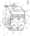
- FIG. 1 a fire extinguishing system valve 1 is shown.
- the fire extinguishing system valve 1 has a housing 3.
- the housing 3 comprises a housing base body 5 and a control module 7, which is reversibly detachably connected to the housing base body 5, preferably by means of screw connections.
- a front panel 6 is mounted on the housing base 5.
- the housing 3 has an inlet-side connection piece 8 and an outlet-side connection piece 10 on the housing base body 5.
- the inlet-side connection piece 8 leads into a fluid inlet chamber 9 (not shown).
- the outlet-side connection piece 10 leads into a fluid outlet chamber 11 (cf. Figure 2 ).
- a first and a second pressure gauge 15a,b are arranged on the front panel 6, wherein the first pressure gauge 15a indicates the pressure in the fluid inlet chamber 9, and the second pressure gauge 15b indicates the pressure in the fluid outlet chamber 11.
- a first connection piece 17 is arranged on the control module 7 and is designed for connection to an alarm line.
- a second connection piece 19 is designed for connection to a drain line.
- the control module 7 has a total of three shut-off devices 21, 23, 25, each of which is operatively connected to handling means, here rotary handles, which are arranged on the housing.
- the first shut-off device 21 is used to selectively close and open a discharge channel arranged inside the housing.
- the second shut-off device 23 is used to selectively close or open a direct alarm channel.
- the third shut-off device 25 is used to selectively close or open an alarm test channel.
- Figure 2 shows the housing base 5 with the housing 3 opened.
- a first and a second connection 27, 29 are formed on the housing base body 5 and are connected to the fluid outlet chamber 11 in a fluid-conducting manner.
- Figure 2 also provides a view of a closing body 13 which, in the locking state shown, prevents the direct transfer of extinguishing agent from the fluid inlet chamber 9 into the fluid outlet chamber 11 and vice versa.
- Two bypass connections 31a, 31b are formed in the housing base body 5, of which the first bypass connection 31a is in fluid communication with the fluid inlet chamber 9, while the second bypass connection 31b is in fluid communication with the fluid outlet chamber 11.
- the housing base body 5 is further provided with an alarm channel connection 33 which leads into the fluid inlet chamber in such a way that it is closed by the closing body 13 when it is in the locked state, and is released when the closing body 13 is opened and is in fluid communication with the fluid inlet chamber 9.
- a direct alarm connection 35 is formed on the housing base body 5, which is fluidically connected to the fluid inlet chamber 9.
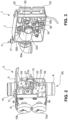
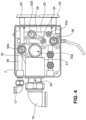
- Figure 3 shows complementary to Figure 2 the second part of the housing 3, namely the control module 7.
- the control module 7 has a series of channels which are connected to the Figure 2 correspond to the connections shown and described.
- the control module 7 has a drain channel 30 which has a first inlet 30a and a second inlet 30b.
- the first inlet 30a of the drain channel 30 is adapted for connection to the first connection 27 of the housing base body 5, while the second inlet 30b is adapted for connection to the second connection 29 of the housing base body 5.
- the control module 7 further comprises a bypass inlet 32a and a bypass outlet 32b, wherein the bypass inlet 32a is adapted for connection to the first bypass connection 31a in the housing base body 5 and the bypass outlet 32b is adapted for connection to the second bypass connection 31b in the housing base body 5.
- the control module 7 further comprises an alarm channel inlet 34 which is adapted for connection to the alarm channel connection 33 in the housing base body 5.
- the control module 7 further comprises a direct alarm channel inlet 36 which is adapted for connection to the direct alarm connection 35 in the housing base body 5.
- an internal non-return valve is preferably reversibly integrated in the housing. This prevents backflow from the fluid outlet chamber 11 to the fluid inlet chamber 9.
- the bypass inlet 32a and the bypass outlet 32b are fluidically connected by means of a bypass channel 32 inside the control module.
- the alarm channel inlet 34 and the direct alarm channel inlet 36 each open into an alarm channel 39 arranged inside the control module, which leads to the connection piece 17 from is led out of the housing.
- the fluid-conducting connection between the alarm channel 39 and the direct alarm channel inlet 36 can be selectively separated or released by means of the shut-off device 23.
- the first drain channel inlet 30a opens into a first branch line 41 of the drain channel 30, while the second drain channel inlet 30b opens into a second branch line 43, which in turn opens into the drain channel 30.
- the drain channel 30 is led out of the housing towards the connection piece 19.
- the second drain channel inlet 30b can be selectively opened or closed by means of the shut-off device 21.
- a hose 52 is mounted on the housing base 5 for draining liquid from the alarm channel 39.
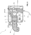
- the shut-off device 21 ( Figure 1 ) is operatively connected to a ball element 47.
- the ball element 47 is in the Figure 5 shown position is switched to an alarm test position. In the position shown, the fluid-conducting connection between the first drain channel inlet 30a and an outlet 30c of the drain channel 30 is interrupted, while extinguishing agent can flow through the second drain channel inlet 30b and the second branch line 43 into the drain channel 30.
- the shut-off device 21 has a first passage 49 with a first cross-section in the ball element 47, as well as a second passage 51 with a second, smaller cross-section.
- the first passage 49 extends completely through the ball element 47, while the second passage 51 opens into the first passage 49.
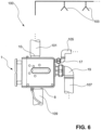
- the flow resistance achieved by the cross-section reduction in the second passage 51 and/or the second branch line 43 preferably results in a K factor in the range of K ⁇ 85, preferably K ⁇ 57, so that switching the shut-off device 25 to the alarm test position activates a sprinkler 103 ( Fig.6 ) is simulated.
- the ball 47 assumes a position compared to the state according to Figure 5 rotated by 90°, in which the first passage 49 is aligned with the first branch line 41 of the discharge channel 30. Extinguishing agent can then flow through the first passage with full cross-section and through the outlet 30c of the discharge channel 30 to the connection piece 19 whereby a significantly larger volume flow is achieved than in the alarm sampling position.
- the shut-off device 21 is rotated by a further 90° so that the ball 47 has a relative to the state according to Figure 5 assumes a position rotated by 180°, the discharge channel 30 is sealed fluid-tight on the outlet side so that no extinguishing agent can flow to the outlet 30c.
- these are both fluid-conductingly connected to the fluid outlet chamber there is no risk of an unwanted fluid leak from the fire extinguishing system valve 1 even if the shut-off device 25 is switched to the blocking position.
- a drain line 107 or a collecting container is preferably connected to the fire extinguishing system valve 1 via the drain connection piece 19.
- An alarm line 105 is preferably connected to the fire extinguishing system valve 1 via the alarm channel connection piece 17.
Landscapes
- Engineering & Computer Science (AREA)
- General Engineering & Computer Science (AREA)
- Health & Medical Sciences (AREA)
- Public Health (AREA)
- Business, Economics & Management (AREA)
- Emergency Management (AREA)
- Mechanical Engineering (AREA)
- Fire-Extinguishing By Fire Departments, And Fire-Extinguishing Equipment And Control Thereof (AREA)
Claims (15)
- Vanne d'installation d'extinction d'incendie (1), en particulier vanne d'alarme humide, d'alarme sèche ou d'eau de pulvérisation avec- un boîtier (3) qui présente une chambre d'entrée de fluide (9), une chambre de sortie de fluide (11) et un corps de fermeture (13) mobile alternativement entre un état de blocage et un état de libération,- dans laquelle la chambre d'entrée de fluide (9) et la chambre de sortie de fluide (11) communiquent entre elles directement de manière à acheminer du fluide dans l'état de libération, et le corps de fermeture (13) empêche, dans l'état de verrouillage, la communication directe entre la chambre d'entrée de fluide (9) et la chambre de sortie de fluide (11),
caractérisée en ce que le boîtier (3) présente un canal d'évacuation (30) dédié qui présente au moins une entrée (30a, b) reliée à la chambre de sortie de fluide (11) et une sortie (30c) menant hors du boîtier (3) de la vanne d'installation d'extinction d'incendie (1), et qui est intégré dans le boîtier (3), et le boîtier (3) présente un module de commande (7) qui est conçue afin de- libérer au choix le canal d'évacuation (30) dédié dans une position d'évacuation en direction de sa sortie ou de le fermer dans une position de blocage de manière étanche au fluide en direction de sa sortie, et- d'évacuer, dans une position d'essai d'alarme, des moyens d'extinction, par le biais d'une section de canal avec une section transversale, hors de la chambre de sortie de fluide, qui est plus petite que la section transversale la plus petite du canal d'évacuation (30) dédié. - Vanne d'installation d'extinction d'incendie (1) selon la revendication 1,
dans laquelle le boîtier (3) présente un corps de base de boîtier (5), dans lequel la chambre d'entrée de fluide (9) et la chambre de sortie de fluide (11) sont réalisées et le corps de fermeture (13) est agencé, et en plus ledit module de commande (7) est relié de manière détachable et réversible au corps de base de boîtier (5), dans laquelle le canal d'évacuation (30) dédié est réalisé dans le module de commande (7). - Vanne d'installation d'extinction d'incendie selon la revendication 1 ou 2,
dans laquelle un organe de blocage (21) est agencé dans le canal d'évacuation (30) dédié, lequel est commutable au choix dans la position de blocage ou la position d'évacuation. - Vanne d'installation d'extinction d'incendie selon l'une quelconque des revendications précédentes,
dans laquelle l'organe de blocage (21) est commutable en outre dans la position d'essai d'alarme, dans laquelle le canal d'évacuation (30) est libéré en direction de sa sortie (30c) avec la section transversale réduite par rapport à la position d'évacuation. - Vanne d'installation d'extinction d'incendie selon la revendication 4,dans laquelle le canal d'évacuation (30) présente, vu depuis l'organe de blocage (21) côté entrée, un premier et un second canal de ramification (41, 43) qui sont reliés respectivement de manière à acheminer le fluide à la chambre de sortie de fluide (11),dans laquelle, dans la position d'évacuation de l'organe de blocage (21), au moins le premier canal de ramification (41) et la sortie (30c) du canal d'évacuation communiquent de manière à acheminer le fluide entre eux,dans la position d'essai d'alarme de l'organe de blocage, exclusivement le second canal de ramification (43) communique avec la sortie (30c) du canal d'évacuation de manière à acheminer le fluide, etdans la position de blocage de l'organe de blocage, ni le premier ni le second canal de ramification ne communiquent avec la sortie du canal d'évacuation.
- Vanne d'installation d'extinction d'incendie selon la revendication 5,dans laquelle l'organe de blocage présente un corps de vanne (47) de préférence sphérique qui présente un premier passage (49) qui s'étend complètement à travers le corps de vanne, etprésente un second passage (51) qui est orienté selon un angle par rapport au premier passage, et débouche de préférence dans le premier passage.
- Vanne d'installation d'extinction d'incendie selon l'une quelconque des revendications 4 à 6,
dans laquelle la réduction de section transversale est réalisée dans le canal d'évacuation et/ou dans l'organe de blocage. - Vanne d'installation d'extinction d'incendie selon l'une quelconque des revendications 1 à 3,
dans laquelle le canal d'évacuation (30) est un premier canal d'évacuation, et la vanne d'installation d'extinction d'incendie présente de plus un second canal d'évacuation relié de manière à acheminer le fluide à la chambre de sortie de fluide, intégré dans le boîtier et menant hors du boîtier, dans laquelle le second canal d'évacuation est réalisé comme canal d'essai d'alarme et présente une section transversale qui est plus petite au moins par sections que la section transversale la plus petite du premier canal d'évacuation. - Vanne d'installation d'extinction d'incendie selon la revendication 8,
dans laquelle le second canal d'évacuation est réalisé dans le module de commande, et de préférence présente un organe de blocage pour le blocage ou la libération au choix du second canal d'évacuation. - Vanne d'installation d'extinction d'incendie selon l'une quelconque des revendications précédentes,
dans laquelle la réduction de section transversale est dimensionnée de telle manière que la résistance à l'écoulement générée par la réduction de section transversale se rapproche au moins de celle d'un gicleur d'incendie ou vanne d'eau de pulvérisation associée à la vanne d'installation d'extinction d'incendie. - Vanne d'installation d'extinction d'incendie (1) selon l'une quelconque des revendications précédentes,
dans laquelle, dans le boîtier (3), en particulier dans le module de commande (7), un canal de dérivation (32) est réalisé, lequel relie de manière à acheminer le fluide la chambre d'entrée de fluide (9) et la chambre de sortie de fluide (11) entre elles, dans laquelle de préférence, dans le canal de dérivation, un organe de blocage est prévu pour le blocage ou la libération au choix du canal de dérivation. - Vanne d'installation d'extinction d'incendie selon l'une quelconque des revendications précédentes,
dans laquelle, dans le boîtier, en particulier dans le module de commande, un canal d'alarme direct (36, 39) est prévu, lequel est relié côté entrée directement, de manière à acheminer le fluide, à la chambre d'entrée de fluide (9) et présente une sortie (17) menant hors du boîtier, en particulier du module de commande, qui est conçue pour le raccordement à une conduite d'alarme externe, en particulier une conduite de sonnette d'alarme, dans laquelle un organe de blocage est de préférence agencé dans le canal d'alarme direct, lequel est commutable au choix dans une position de blocage ou une position de libération. - Vanne d'installation d'extinction d'incendie selon l'une quelconque des revendications précédentes,
dans laquelle un canal d'alarme (34, 39) est agencé dans le boîtier, de préférence dans le corps de base de boîtier et/ou le module de commande, dans laquelle le canal d'alarme est agencé de telle manière qu'il soit bloqué aussi dans l'état de blocage du corps de fermeture (13), et qu'il soit inondé quand le corps de fermeture est ouvert, dans lequel le canal d'alarme s'étend à travers le boîtier, en particulier le module de commande, et présente une sortie menant hors du boîtier, en particulier du module de commande, qui est conçue pour le raccordement à une conduite d'alarme externe, en particulier une conduite de sonnette d'alarme. - Module de commande (7) pour une vanne d'installation d'extinction d'incendie (1), en particulier vanne d'alarme humide, d'alarme sèche ou d'eau de pulvérisation selon l'une quelconque des revendications précédentes, avecdes moyens de fixation pour la liaison amovible et réversible avec des moyens de fixation correspondants d'un corps de base de boîtier de la vanne d'installation d'extinction d'incendie, etun canal d'évacuation (30) dédié qui présente au moins une entrée (30a, b) et une sortie (30c), et est intégré dans le module de commande, dans lequell'au moins une entrée et la sortie sont agencées de telle manière qu'en cas de corps de base de boîtier (5) relié au module de commande, l'entrée (30a.b) est reliée à une chambre de sortie de fluide (11) de la vanne d'installation d'extinction d'incendie (1), et qui est conçu afin de libérer au choix le canal d'évacuation (30) dédié dans une position de sortie en direction de sa sortie ou de le fermer dans une position de blocage de manière étanche au fluide en direction de sa sortie, et d'évacuer, dans une position d'essai d'alarme, du fluide d'extinction par le biais d'une section de canal avec une section transversale, hors de la chambre de sortie de fluide, qui est plus petite que la section transversale la plus petite du canal d'évacuation (30) dédié.
- Installation d'extinction d'incendie (100), en particulier installation de gicleur d'incendie, avec une ou plusieurs conduites de fluide (101), dans lesquelles une vanne d'installation d'extinction d'incendie (1) est agencée pour le blocage et la libération des conduites de fluide (101),
caractérisée en ce que la vanne d'installation d'extinction d'incendie (1) est réalisée selon l'une quelconque des revendications 1 à 13.
Applications Claiming Priority (2)
| Application Number | Priority Date | Filing Date | Title |
|---|---|---|---|
| DE102017117417.6A DE102017117417A1 (de) | 2017-08-01 | 2017-08-01 | Feuerlöschanlagenventil, insbesondere Nassalarm-, Trockenalarm-, oder Sprühwasserventil sowie Steuermodul für selbiges und Feuerlöschanlage mit selbigem |
| PCT/EP2018/070884 WO2019025495A1 (fr) | 2017-08-01 | 2018-08-01 | Vanne d'installation d'extinction d'incendie, en particulier vanne d'alarme humide, d'alarme sèche ou d'eau de pulvérisation ainsi que module de commande pour celle-ci et installation d'extinction d'incendie équipée de celle-ci |
Publications (2)
| Publication Number | Publication Date |
|---|---|
| EP3661609A1 EP3661609A1 (fr) | 2020-06-10 |
| EP3661609B1 true EP3661609B1 (fr) | 2024-07-03 |
Family
ID=63442593
Family Applications (1)
| Application Number | Title | Priority Date | Filing Date |
|---|---|---|---|
| EP18762226.1A Active EP3661609B1 (fr) | 2017-08-01 | 2018-08-01 | Vanne d'installation d'extinction d'incendie, en particulier vanne d'alarme humide, d'alarme sèche ou d'eau de pulvérisation ainsi que module de commande pour celle-ci et installation d'extinction d'incendie équipée de celle-ci |
Country Status (5)
| Country | Link |
|---|---|
| US (1) | US11504561B2 (fr) |
| EP (1) | EP3661609B1 (fr) |
| CN (1) | CN110997080B (fr) |
| DE (1) | DE102017117417A1 (fr) |
| WO (1) | WO2019025495A1 (fr) |
Families Citing this family (5)
| Publication number | Priority date | Publication date | Assignee | Title |
|---|---|---|---|---|
| DE102017116117A1 (de) | 2017-07-18 | 2019-01-24 | Minimax Gmbh & Co. Kg | Feuerlöschanlagenventil, sowie Feuerlöschanlage mit selbigem |
| DE102017117426A1 (de) | 2017-08-01 | 2019-02-07 | Minimax Gmbh & Co. Kg | Feuerlöschanlagenventil |
| DE102018119798A1 (de) * | 2018-08-15 | 2020-02-20 | Fogtec Brandschutz Gmbh & Co. Kg | Verfahren zur Überwachung von Ventilen |
| CN116075338B (zh) * | 2020-10-20 | 2025-12-02 | 泰科消防产品有限合伙公司 | 干管式歧管系统和方法 |
| US20240108926A1 (en) * | 2022-10-03 | 2024-04-04 | Jeremy Ryan Bradfield | Systems, methods, and apparatuses for implementing in-situ configurable diffusion characteristics of mass water flows |
Family Cites Families (21)
| Publication number | Priority date | Publication date | Assignee | Title |
|---|---|---|---|---|
| DE324354C (de) * | 1915-09-16 | 1920-08-24 | Clemens Rickert | Selbsttaetiges Absperrventil fuer Feuerloescheinrichtungen nach dem sog. Trockenverfahren |
| US1553884A (en) * | 1922-03-10 | 1925-09-15 | Tyden Emil | Dry-pipe valve |
| US2003884A (en) * | 1933-02-02 | 1935-06-04 | Halford Marion Eugene | Control valve for automatic sprinkler systems |
| DE1239571B (de) * | 1961-05-12 | 1967-04-27 | Walther & Cie Ag | Nassalarmventil fuer Feuerloeschanlagen |
| US4993453A (en) * | 1986-06-16 | 1991-02-19 | Agf Manufacturing, Inc. | Valve and arrangement for fire suppression water sprinkler system |
| US6068057A (en) * | 1998-05-15 | 2000-05-30 | Reliable Automatic Sprinkler Co., Inc. | Dry pipe valve system |
| US6810910B2 (en) * | 1999-01-22 | 2004-11-02 | Agf Manufacturing, Inc. | Valve and arrangement for fire suppression system |
| US7152622B2 (en) * | 2004-11-16 | 2006-12-26 | Valve Innovations, Llc | Check valve |
| DE102007049588B4 (de) | 2007-10-15 | 2012-06-14 | Minimax Gmbh & Co. Kg | Elektrisch gesteuerter Schnellentlüfter für ein Trockenrohrnetz mit Sprinklern |
| WO2009130903A1 (fr) * | 2008-04-23 | 2009-10-29 | 千住スプリンクラー株式会社 | Dispositif de détection d'écoulement d'eau |
| WO2010146679A1 (fr) * | 2009-06-17 | 2010-12-23 | 千住スプリンクラー株式会社 | Detecteur d'eau en ecoulement |
| JP5275938B2 (ja) * | 2009-08-05 | 2013-08-28 | 前澤給装工業株式会社 | 流量調整止水栓 |
| CN203309202U (zh) * | 2013-06-20 | 2013-11-27 | 浙江工商职业技术学院 | 一种无潴留多路控制球阀 |
| US9265980B2 (en) * | 2013-06-24 | 2016-02-23 | Augustus W. Johnson | Flow control assembly for a fire sprinkler system |
| DE102014226639A1 (de) | 2014-12-19 | 2016-06-23 | Minimax Gmbh & Co. Kg | Feuerlöschanlagenventile und Feuerlöschanlagen mit selbigen |
| CN205118301U (zh) * | 2015-10-28 | 2016-03-30 | 威森节能科技(天津)有限公司 | 一种新型流量调节装置 |
| US10596401B2 (en) * | 2016-08-11 | 2020-03-24 | Victaulic Company | Modular valve assembly |
| DE102016124475A1 (de) | 2016-12-15 | 2018-06-21 | Minimax Gmbh & Co. Kg | Feuerlöschanlagenventil, insbesondere Nassalarm-, Trockenalarm- oder Sprühwasserventil, und Feuerlöschanlage mit selbigem |
| DE102017116117A1 (de) | 2017-07-18 | 2019-01-24 | Minimax Gmbh & Co. Kg | Feuerlöschanlagenventil, sowie Feuerlöschanlage mit selbigem |
| USD890301S1 (en) | 2017-08-04 | 2020-07-14 | Minimax Viking GmbH & Co. KG | Valve |
| DE102018100983A1 (de) | 2018-01-17 | 2019-07-18 | Minimax Gmbh & Co. Kg | Komponente für eine Brandschutzanlage, Verfahren zur Herstellung derselben und Brandschutzanlage mit selbigem |
-
2017
- 2017-08-01 DE DE102017117417.6A patent/DE102017117417A1/de not_active Withdrawn
-
2018
- 2018-08-01 US US16/635,158 patent/US11504561B2/en active Active
- 2018-08-01 WO PCT/EP2018/070884 patent/WO2019025495A1/fr not_active Ceased
- 2018-08-01 CN CN201880050401.4A patent/CN110997080B/zh active Active
- 2018-08-01 EP EP18762226.1A patent/EP3661609B1/fr active Active
Also Published As
| Publication number | Publication date |
|---|---|
| EP3661609A1 (fr) | 2020-06-10 |
| US20210086008A1 (en) | 2021-03-25 |
| DE102017117417A1 (de) | 2019-02-07 |
| WO2019025495A1 (fr) | 2019-02-07 |
| US11504561B2 (en) | 2022-11-22 |
| CN110997080A (zh) | 2020-04-10 |
| CN110997080B (zh) | 2022-04-01 |
Similar Documents
| Publication | Publication Date | Title |
|---|---|---|
| EP3661609B1 (fr) | Vanne d'installation d'extinction d'incendie, en particulier vanne d'alarme humide, d'alarme sèche ou d'eau de pulvérisation ainsi que module de commande pour celle-ci et installation d'extinction d'incendie équipée de celle-ci | |
| EP3554652B1 (fr) | Vanne d'installation d'extinction d'incendie, en particulier vanne d'alarme humide, d'alarme sèche ou d'eau de pulvérisation, et installation d'extinction d'incendie équipée de celle-ci | |
| EP1681520A2 (fr) | vanne pour de fluide | |
| EP1861176B1 (fr) | Valve d'entretien facile destinee a des systemes de lutte contre un incendie | |
| EP3727610B1 (fr) | Appareil de commande pneumatique pour des installations d'extinction d'incendie multizone, ainsi qu'installation d'extinction d'incendie multizone le comprenant | |
| EP3655115B1 (fr) | Vanne d'installation d'extinction d'incendie et installation d'extinction d'incendie équipée de celle-ci | |
| DE19529959C2 (de) | Anschlußarmatur zum Anschließen eines Membrandruckausdehnungsgefäßes an ein Leitungsnetz | |
| DE102009031044B4 (de) | Anschluss einer sekundären Leitung einer Reinwasser-Hauptversorgungsleitung an ein Dialysegerät oder dergleichen | |
| DE2611653C2 (de) | Sprinkleranlage | |
| DE102010032575A1 (de) | Steckscheibe für den Einbau zwischen zwei Flanschen einer Flanschverbindung | |
| EP3416731B1 (fr) | Station de vanne d'alarme d'un système d'extinction d'incendie et système d'extinction d'incendie | |
| EP4008844B1 (fr) | Système de protection contre les fuites | |
| DE102016211240B4 (de) | Sprühwasserventilstation für eine Feuerlöschanlage und Feuerlöschanlage | |
| DE3937778C2 (de) | Alarmventilstation | |
| DE202013005960U1 (de) | 3/2-Kugelabsperrventil für zwei Anschlussrichtungen | |
| DE19812272A1 (de) | Sicherheitsanschlußstück zum Anschließen eines Ausdehnungsgefäßes an einen geschlossenen Fluidkreislauf | |
| DE2920923A1 (de) | Warmwasserheizungs- oder bereitungsanlage mit einer regelbaren strahlpumpe und strahlpumpe dazu | |
| DE662339C (de) | Vorrichtung zum selbsttaetigen Abschalten und Umgehen einer UEberwachungseinrichtung fuer Dampfwasserableiter | |
| EP3330444B1 (fr) | Structure d'écoulement avec soupape antirétour | |
| DE1279563B (de) | Vorrichtung zur Rueckflussverhinderung in Wasserleitungen | |
| DE202005021484U1 (de) | Servicefreundliches Ventil für Brandbekämpfungssysteme | |
| DE29724632U1 (de) | Zwei-Wege-Kugelhahn | |
| DE9212338U1 (de) | Rückströmsichere Vorrichtung für Feuerlöschanlagen |
Legal Events
| Date | Code | Title | Description |
|---|---|---|---|
| STAA | Information on the status of an ep patent application or granted ep patent |
Free format text: STATUS: UNKNOWN |
|
| STAA | Information on the status of an ep patent application or granted ep patent |
Free format text: STATUS: THE INTERNATIONAL PUBLICATION HAS BEEN MADE |
|
| PUAI | Public reference made under article 153(3) epc to a published international application that has entered the european phase |
Free format text: ORIGINAL CODE: 0009012 |
|
| STAA | Information on the status of an ep patent application or granted ep patent |
Free format text: STATUS: REQUEST FOR EXAMINATION WAS MADE |
|
| 17P | Request for examination filed |
Effective date: 20200302 |
|
| AK | Designated contracting states |
Kind code of ref document: A1 Designated state(s): AL AT BE BG CH CY CZ DE DK EE ES FI FR GB GR HR HU IE IS IT LI LT LU LV MC MK MT NL NO PL PT RO RS SE SI SK SM TR |
|
| AX | Request for extension of the european patent |
Extension state: BA ME |
|
| RIN1 | Information on inventor provided before grant (corrected) |
Inventor name: ENGELSMAN, EDUARD Inventor name: STACHOWITZ, FRANK Inventor name: KEMPF, PETER |
|
| DAV | Request for validation of the european patent (deleted) | ||
| DAX | Request for extension of the european patent (deleted) | ||
| RAP3 | Party data changed (applicant data changed or rights of an application transferred) |
Owner name: MINIMAX GMBH |
|
| P01 | Opt-out of the competence of the unified patent court (upc) registered |
Effective date: 20230601 |
|
| GRAP | Despatch of communication of intention to grant a patent |
Free format text: ORIGINAL CODE: EPIDOSNIGR1 |
|
| STAA | Information on the status of an ep patent application or granted ep patent |
Free format text: STATUS: GRANT OF PATENT IS INTENDED |
|
| INTG | Intention to grant announced |
Effective date: 20230908 |
|
| GRAJ | Information related to disapproval of communication of intention to grant by the applicant or resumption of examination proceedings by the epo deleted |
Free format text: ORIGINAL CODE: EPIDOSDIGR1 |
|
| STAA | Information on the status of an ep patent application or granted ep patent |
Free format text: STATUS: REQUEST FOR EXAMINATION WAS MADE |
|
| INTC | Intention to grant announced (deleted) | ||
| GRAP | Despatch of communication of intention to grant a patent |
Free format text: ORIGINAL CODE: EPIDOSNIGR1 |
|
| STAA | Information on the status of an ep patent application or granted ep patent |
Free format text: STATUS: GRANT OF PATENT IS INTENDED |
|
| INTG | Intention to grant announced |
Effective date: 20240227 |
|
| GRAS | Grant fee paid |
Free format text: ORIGINAL CODE: EPIDOSNIGR3 |
|
| GRAA | (expected) grant |
Free format text: ORIGINAL CODE: 0009210 |
|
| STAA | Information on the status of an ep patent application or granted ep patent |
Free format text: STATUS: THE PATENT HAS BEEN GRANTED |
|
| AK | Designated contracting states |
Kind code of ref document: B1 Designated state(s): AL AT BE BG CH CY CZ DE DK EE ES FI FR GB GR HR HU IE IS IT LI LT LU LV MC MK MT NL NO PL PT RO RS SE SI SK SM TR |
|
| REG | Reference to a national code |
Ref country code: CH Ref legal event code: EP |
|
| REG | Reference to a national code |
Ref country code: DE Ref legal event code: R096 Ref document number: 502018014816 Country of ref document: DE |
|
| REG | Reference to a national code |
Ref country code: LT Ref legal event code: MG9D |
|
| REG | Reference to a national code |
Ref country code: NL Ref legal event code: MP Effective date: 20240703 |
|
| PG25 | Lapsed in a contracting state [announced via postgrant information from national office to epo] |
Ref country code: PT Free format text: LAPSE BECAUSE OF FAILURE TO SUBMIT A TRANSLATION OF THE DESCRIPTION OR TO PAY THE FEE WITHIN THE PRESCRIBED TIME-LIMIT Effective date: 20241104 |
|
| PG25 | Lapsed in a contracting state [announced via postgrant information from national office to epo] |
Ref country code: NL Free format text: LAPSE BECAUSE OF FAILURE TO SUBMIT A TRANSLATION OF THE DESCRIPTION OR TO PAY THE FEE WITHIN THE PRESCRIBED TIME-LIMIT Effective date: 20240703 |
|
| PG25 | Lapsed in a contracting state [announced via postgrant information from national office to epo] |
Ref country code: PT Free format text: LAPSE BECAUSE OF FAILURE TO SUBMIT A TRANSLATION OF THE DESCRIPTION OR TO PAY THE FEE WITHIN THE PRESCRIBED TIME-LIMIT Effective date: 20241104 Ref country code: NL Free format text: LAPSE BECAUSE OF FAILURE TO SUBMIT A TRANSLATION OF THE DESCRIPTION OR TO PAY THE FEE WITHIN THE PRESCRIBED TIME-LIMIT Effective date: 20240703 |
|
| PG25 | Lapsed in a contracting state [announced via postgrant information from national office to epo] |
Ref country code: NO Free format text: LAPSE BECAUSE OF FAILURE TO SUBMIT A TRANSLATION OF THE DESCRIPTION OR TO PAY THE FEE WITHIN THE PRESCRIBED TIME-LIMIT Effective date: 20241003 |
|
| PG25 | Lapsed in a contracting state [announced via postgrant information from national office to epo] |
Ref country code: GR Free format text: LAPSE BECAUSE OF FAILURE TO SUBMIT A TRANSLATION OF THE DESCRIPTION OR TO PAY THE FEE WITHIN THE PRESCRIBED TIME-LIMIT Effective date: 20241004 Ref country code: FI Free format text: LAPSE BECAUSE OF FAILURE TO SUBMIT A TRANSLATION OF THE DESCRIPTION OR TO PAY THE FEE WITHIN THE PRESCRIBED TIME-LIMIT Effective date: 20240703 Ref country code: PL Free format text: LAPSE BECAUSE OF FAILURE TO SUBMIT A TRANSLATION OF THE DESCRIPTION OR TO PAY THE FEE WITHIN THE PRESCRIBED TIME-LIMIT Effective date: 20240703 |
|
| PG25 | Lapsed in a contracting state [announced via postgrant information from national office to epo] |
Ref country code: BG Free format text: LAPSE BECAUSE OF FAILURE TO SUBMIT A TRANSLATION OF THE DESCRIPTION OR TO PAY THE FEE WITHIN THE PRESCRIBED TIME-LIMIT Effective date: 20240703 |
|
| PG25 | Lapsed in a contracting state [announced via postgrant information from national office to epo] |
Ref country code: LV Free format text: LAPSE BECAUSE OF FAILURE TO SUBMIT A TRANSLATION OF THE DESCRIPTION OR TO PAY THE FEE WITHIN THE PRESCRIBED TIME-LIMIT Effective date: 20240703 |
|
| PG25 | Lapsed in a contracting state [announced via postgrant information from national office to epo] |
Ref country code: IS Free format text: LAPSE BECAUSE OF FAILURE TO SUBMIT A TRANSLATION OF THE DESCRIPTION OR TO PAY THE FEE WITHIN THE PRESCRIBED TIME-LIMIT Effective date: 20241103 |
|
| PG25 | Lapsed in a contracting state [announced via postgrant information from national office to epo] |
Ref country code: CZ Free format text: LAPSE BECAUSE OF FAILURE TO SUBMIT A TRANSLATION OF THE DESCRIPTION OR TO PAY THE FEE WITHIN THE PRESCRIBED TIME-LIMIT Effective date: 20240703 Ref country code: HR Free format text: LAPSE BECAUSE OF FAILURE TO SUBMIT A TRANSLATION OF THE DESCRIPTION OR TO PAY THE FEE WITHIN THE PRESCRIBED TIME-LIMIT Effective date: 20240703 |
|
| PG25 | Lapsed in a contracting state [announced via postgrant information from national office to epo] |
Ref country code: RS Free format text: LAPSE BECAUSE OF FAILURE TO SUBMIT A TRANSLATION OF THE DESCRIPTION OR TO PAY THE FEE WITHIN THE PRESCRIBED TIME-LIMIT Effective date: 20241003 Ref country code: ES Free format text: LAPSE BECAUSE OF FAILURE TO SUBMIT A TRANSLATION OF THE DESCRIPTION OR TO PAY THE FEE WITHIN THE PRESCRIBED TIME-LIMIT Effective date: 20240703 |
|
| PG25 | Lapsed in a contracting state [announced via postgrant information from national office to epo] |
Ref country code: RS Free format text: LAPSE BECAUSE OF FAILURE TO SUBMIT A TRANSLATION OF THE DESCRIPTION OR TO PAY THE FEE WITHIN THE PRESCRIBED TIME-LIMIT Effective date: 20241003 Ref country code: PL Free format text: LAPSE BECAUSE OF FAILURE TO SUBMIT A TRANSLATION OF THE DESCRIPTION OR TO PAY THE FEE WITHIN THE PRESCRIBED TIME-LIMIT Effective date: 20240703 Ref country code: NO Free format text: LAPSE BECAUSE OF FAILURE TO SUBMIT A TRANSLATION OF THE DESCRIPTION OR TO PAY THE FEE WITHIN THE PRESCRIBED TIME-LIMIT Effective date: 20241003 Ref country code: LV Free format text: LAPSE BECAUSE OF FAILURE TO SUBMIT A TRANSLATION OF THE DESCRIPTION OR TO PAY THE FEE WITHIN THE PRESCRIBED TIME-LIMIT Effective date: 20240703 Ref country code: IS Free format text: LAPSE BECAUSE OF FAILURE TO SUBMIT A TRANSLATION OF THE DESCRIPTION OR TO PAY THE FEE WITHIN THE PRESCRIBED TIME-LIMIT Effective date: 20241103 Ref country code: HR Free format text: LAPSE BECAUSE OF FAILURE TO SUBMIT A TRANSLATION OF THE DESCRIPTION OR TO PAY THE FEE WITHIN THE PRESCRIBED TIME-LIMIT Effective date: 20240703 Ref country code: GR Free format text: LAPSE BECAUSE OF FAILURE TO SUBMIT A TRANSLATION OF THE DESCRIPTION OR TO PAY THE FEE WITHIN THE PRESCRIBED TIME-LIMIT Effective date: 20241004 Ref country code: FI Free format text: LAPSE BECAUSE OF FAILURE TO SUBMIT A TRANSLATION OF THE DESCRIPTION OR TO PAY THE FEE WITHIN THE PRESCRIBED TIME-LIMIT Effective date: 20240703 Ref country code: ES Free format text: LAPSE BECAUSE OF FAILURE TO SUBMIT A TRANSLATION OF THE DESCRIPTION OR TO PAY THE FEE WITHIN THE PRESCRIBED TIME-LIMIT Effective date: 20240703 Ref country code: CZ Free format text: LAPSE BECAUSE OF FAILURE TO SUBMIT A TRANSLATION OF THE DESCRIPTION OR TO PAY THE FEE WITHIN THE PRESCRIBED TIME-LIMIT Effective date: 20240703 Ref country code: BG Free format text: LAPSE BECAUSE OF FAILURE TO SUBMIT A TRANSLATION OF THE DESCRIPTION OR TO PAY THE FEE WITHIN THE PRESCRIBED TIME-LIMIT Effective date: 20240703 |
|
| REG | Reference to a national code |
Ref country code: CH Ref legal event code: PL |
|
| REG | Reference to a national code |
Ref country code: DE Ref legal event code: R097 Ref document number: 502018014816 Country of ref document: DE |
|
| PG25 | Lapsed in a contracting state [announced via postgrant information from national office to epo] |
Ref country code: RO Free format text: LAPSE BECAUSE OF FAILURE TO SUBMIT A TRANSLATION OF THE DESCRIPTION OR TO PAY THE FEE WITHIN THE PRESCRIBED TIME-LIMIT Effective date: 20240703 Ref country code: DK Free format text: LAPSE BECAUSE OF FAILURE TO SUBMIT A TRANSLATION OF THE DESCRIPTION OR TO PAY THE FEE WITHIN THE PRESCRIBED TIME-LIMIT Effective date: 20240703 Ref country code: SM Free format text: LAPSE BECAUSE OF FAILURE TO SUBMIT A TRANSLATION OF THE DESCRIPTION OR TO PAY THE FEE WITHIN THE PRESCRIBED TIME-LIMIT Effective date: 20240703 |
|
| PG25 | Lapsed in a contracting state [announced via postgrant information from national office to epo] |
Ref country code: LU Free format text: LAPSE BECAUSE OF NON-PAYMENT OF DUE FEES Effective date: 20240801 |
|
| PG25 | Lapsed in a contracting state [announced via postgrant information from national office to epo] |
Ref country code: CH Free format text: LAPSE BECAUSE OF NON-PAYMENT OF DUE FEES Effective date: 20240831 Ref country code: MC Free format text: LAPSE BECAUSE OF FAILURE TO SUBMIT A TRANSLATION OF THE DESCRIPTION OR TO PAY THE FEE WITHIN THE PRESCRIBED TIME-LIMIT Effective date: 20240703 Ref country code: EE Free format text: LAPSE BECAUSE OF FAILURE TO SUBMIT A TRANSLATION OF THE DESCRIPTION OR TO PAY THE FEE WITHIN THE PRESCRIBED TIME-LIMIT Effective date: 20240703 |
|
| PG25 | Lapsed in a contracting state [announced via postgrant information from national office to epo] |
Ref country code: SK Free format text: LAPSE BECAUSE OF FAILURE TO SUBMIT A TRANSLATION OF THE DESCRIPTION OR TO PAY THE FEE WITHIN THE PRESCRIBED TIME-LIMIT Effective date: 20240703 Ref country code: IT Free format text: LAPSE BECAUSE OF FAILURE TO SUBMIT A TRANSLATION OF THE DESCRIPTION OR TO PAY THE FEE WITHIN THE PRESCRIBED TIME-LIMIT Effective date: 20240703 |
|
| PLBE | No opposition filed within time limit |
Free format text: ORIGINAL CODE: 0009261 |
|
| STAA | Information on the status of an ep patent application or granted ep patent |
Free format text: STATUS: NO OPPOSITION FILED WITHIN TIME LIMIT |
|
| 26N | No opposition filed |
Effective date: 20250404 |
|
| REG | Reference to a national code |
Ref country code: BE Ref legal event code: MM Effective date: 20240831 |
|
| PG25 | Lapsed in a contracting state [announced via postgrant information from national office to epo] |
Ref country code: BE Free format text: LAPSE BECAUSE OF NON-PAYMENT OF DUE FEES Effective date: 20240831 |
|
| PG25 | Lapsed in a contracting state [announced via postgrant information from national office to epo] |
Ref country code: IE Free format text: LAPSE BECAUSE OF NON-PAYMENT OF DUE FEES Effective date: 20240801 |
|
| PG25 | Lapsed in a contracting state [announced via postgrant information from national office to epo] |
Ref country code: SE Free format text: LAPSE BECAUSE OF FAILURE TO SUBMIT A TRANSLATION OF THE DESCRIPTION OR TO PAY THE FEE WITHIN THE PRESCRIBED TIME-LIMIT Effective date: 20240703 |
|
| PGFP | Annual fee paid to national office [announced via postgrant information from national office to epo] |
Ref country code: DE Payment date: 20250908 Year of fee payment: 8 |
|
| REG | Reference to a national code |
Ref country code: AT Ref legal event code: MM01 Ref document number: 1699201 Country of ref document: AT Kind code of ref document: T Effective date: 20240801 |
|
| PGFP | Annual fee paid to national office [announced via postgrant information from national office to epo] |
Ref country code: GB Payment date: 20250822 Year of fee payment: 8 |
|
| PG25 | Lapsed in a contracting state [announced via postgrant information from national office to epo] |
Ref country code: AT Free format text: LAPSE BECAUSE OF NON-PAYMENT OF DUE FEES Effective date: 20240801 |
|
| PGFP | Annual fee paid to national office [announced via postgrant information from national office to epo] |
Ref country code: FR Payment date: 20250821 Year of fee payment: 8 |
|
| PG25 | Lapsed in a contracting state [announced via postgrant information from national office to epo] |
Ref country code: CY Free format text: LAPSE BECAUSE OF FAILURE TO SUBMIT A TRANSLATION OF THE DESCRIPTION OR TO PAY THE FEE WITHIN THE PRESCRIBED TIME-LIMIT; INVALID AB INITIO Effective date: 20180801 |
|
| PG25 | Lapsed in a contracting state [announced via postgrant information from national office to epo] |
Ref country code: HU Free format text: LAPSE BECAUSE OF FAILURE TO SUBMIT A TRANSLATION OF THE DESCRIPTION OR TO PAY THE FEE WITHIN THE PRESCRIBED TIME-LIMIT; INVALID AB INITIO Effective date: 20180801 |