EP3661733B1 - Verfahren zum zusammenbau eines metallteils mit einem verbundteil und entsprechender zusammenbau von teilen - Google Patents
Verfahren zum zusammenbau eines metallteils mit einem verbundteil und entsprechender zusammenbau von teilen Download PDFInfo
- Publication number
- EP3661733B1 EP3661733B1 EP18737636.3A EP18737636A EP3661733B1 EP 3661733 B1 EP3661733 B1 EP 3661733B1 EP 18737636 A EP18737636 A EP 18737636A EP 3661733 B1 EP3661733 B1 EP 3661733B1
- Authority
- EP
- European Patent Office
- Prior art keywords
- teeth
- tooth
- fibers
- assembly according
- width
- Prior art date
- Legal status (The legal status is an assumption and is not a legal conclusion. Google has not performed a legal analysis and makes no representation as to the accuracy of the status listed.)
- Active
Links
Images


Classifications
-
- B—PERFORMING OPERATIONS; TRANSPORTING
- B29—WORKING OF PLASTICS; WORKING OF SUBSTANCES IN A PLASTIC STATE IN GENERAL
- B29C—SHAPING OR JOINING OF PLASTICS; SHAPING OF MATERIAL IN A PLASTIC STATE, NOT OTHERWISE PROVIDED FOR; AFTER-TREATMENT OF THE SHAPED PRODUCTS, e.g. REPAIRING
- B29C65/00—Joining or sealing of preformed parts, e.g. welding of plastics materials; Apparatus therefor
- B29C65/56—Joining or sealing of preformed parts, e.g. welding of plastics materials; Apparatus therefor using mechanical means or mechanical connections, e.g. form-fits
- B29C65/60—Riveting or staking
- B29C65/606—Riveting or staking the rivets being integral with one of the parts to be joined, i.e. staking
- B29C65/609—Riveting or staking the rivets being integral with one of the parts to be joined, i.e. staking the integral rivets being plunge-formed
-
- F—MECHANICAL ENGINEERING; LIGHTING; HEATING; WEAPONS; BLASTING
- F16—ENGINEERING ELEMENTS AND UNITS; GENERAL MEASURES FOR PRODUCING AND MAINTAINING EFFECTIVE FUNCTIONING OF MACHINES OR INSTALLATIONS; THERMAL INSULATION IN GENERAL
- F16B—DEVICES FOR FASTENING OR SECURING CONSTRUCTIONAL ELEMENTS OR MACHINE PARTS TOGETHER, e.g. NAILS, BOLTS, CIRCLIPS, CLAMPS, CLIPS OR WEDGES; JOINTS OR JOINTING
- F16B5/00—Joining sheets or plates, e.g. panels, to one another or to strips or bars parallel to them
- F16B5/06—Joining sheets or plates, e.g. panels, to one another or to strips or bars parallel to them by means of clamps or clips
- F16B5/0607—Joining sheets or plates, e.g. panels, to one another or to strips or bars parallel to them by means of clamps or clips joining sheets or plates to each other
- F16B5/0621—Joining sheets or plates, e.g. panels, to one another or to strips or bars parallel to them by means of clamps or clips joining sheets or plates to each other in parallel relationship
- F16B5/0635—Joining sheets or plates, e.g. panels, to one another or to strips or bars parallel to them by means of clamps or clips joining sheets or plates to each other in parallel relationship fastened over the edges of the sheets or plates
-
- B—PERFORMING OPERATIONS; TRANSPORTING
- B29—WORKING OF PLASTICS; WORKING OF SUBSTANCES IN A PLASTIC STATE IN GENERAL
- B29C—SHAPING OR JOINING OF PLASTICS; SHAPING OF MATERIAL IN A PLASTIC STATE, NOT OTHERWISE PROVIDED FOR; AFTER-TREATMENT OF THE SHAPED PRODUCTS, e.g. REPAIRING
- B29C65/00—Joining or sealing of preformed parts, e.g. welding of plastics materials; Apparatus therefor
- B29C65/56—Joining or sealing of preformed parts, e.g. welding of plastics materials; Apparatus therefor using mechanical means or mechanical connections, e.g. form-fits
- B29C65/64—Joining a non-plastics element to a plastics element, e.g. by force
-
- B—PERFORMING OPERATIONS; TRANSPORTING
- B29—WORKING OF PLASTICS; WORKING OF SUBSTANCES IN A PLASTIC STATE IN GENERAL
- B29C—SHAPING OR JOINING OF PLASTICS; SHAPING OF MATERIAL IN A PLASTIC STATE, NOT OTHERWISE PROVIDED FOR; AFTER-TREATMENT OF THE SHAPED PRODUCTS, e.g. REPAIRING
- B29C66/00—General aspects of processes or apparatus for joining preformed parts
- B29C66/01—General aspects dealing with the joint area or with the area to be joined
- B29C66/05—Particular design of joint configurations
- B29C66/10—Particular design of joint configurations particular design of the joint cross-sections
- B29C66/11—Joint cross-sections comprising a single joint-segment, i.e. one of the parts to be joined comprising a single joint-segment in the joint cross-section
- B29C66/112—Single lapped joints
- B29C66/1122—Single lap to lap joints, i.e. overlap joints
-
- B—PERFORMING OPERATIONS; TRANSPORTING
- B29—WORKING OF PLASTICS; WORKING OF SUBSTANCES IN A PLASTIC STATE IN GENERAL
- B29C—SHAPING OR JOINING OF PLASTICS; SHAPING OF MATERIAL IN A PLASTIC STATE, NOT OTHERWISE PROVIDED FOR; AFTER-TREATMENT OF THE SHAPED PRODUCTS, e.g. REPAIRING
- B29C66/00—General aspects of processes or apparatus for joining preformed parts
- B29C66/01—General aspects dealing with the joint area or with the area to be joined
- B29C66/05—Particular design of joint configurations
- B29C66/20—Particular design of joint configurations particular design of the joint lines, e.g. of the weld lines
- B29C66/21—Particular design of joint configurations particular design of the joint lines, e.g. of the weld lines said joint lines being formed by a single dot or dash or by several dots or dashes, i.e. spot joining or spot welding
-
- B—PERFORMING OPERATIONS; TRANSPORTING
- B29—WORKING OF PLASTICS; WORKING OF SUBSTANCES IN A PLASTIC STATE IN GENERAL
- B29C—SHAPING OR JOINING OF PLASTICS; SHAPING OF MATERIAL IN A PLASTIC STATE, NOT OTHERWISE PROVIDED FOR; AFTER-TREATMENT OF THE SHAPED PRODUCTS, e.g. REPAIRING
- B29C66/00—General aspects of processes or apparatus for joining preformed parts
- B29C66/01—General aspects dealing with the joint area or with the area to be joined
- B29C66/05—Particular design of joint configurations
- B29C66/303—Particular design of joint configurations the joint involving an anchoring effect
- B29C66/3032—Particular design of joint configurations the joint involving an anchoring effect making use of protrusions or cavities belonging to at least one of the parts to be joined
- B29C66/30321—Particular design of joint configurations the joint involving an anchoring effect making use of protrusions or cavities belonging to at least one of the parts to be joined making use of protrusions belonging to at least one of the parts to be joined
-
- B—PERFORMING OPERATIONS; TRANSPORTING
- B29—WORKING OF PLASTICS; WORKING OF SUBSTANCES IN A PLASTIC STATE IN GENERAL
- B29C—SHAPING OR JOINING OF PLASTICS; SHAPING OF MATERIAL IN A PLASTIC STATE, NOT OTHERWISE PROVIDED FOR; AFTER-TREATMENT OF THE SHAPED PRODUCTS, e.g. REPAIRING
- B29C66/00—General aspects of processes or apparatus for joining preformed parts
- B29C66/01—General aspects dealing with the joint area or with the area to be joined
- B29C66/05—Particular design of joint configurations
- B29C66/303—Particular design of joint configurations the joint involving an anchoring effect
- B29C66/3034—Particular design of joint configurations the joint involving an anchoring effect making use of additional elements, e.g. meshes
-
- B—PERFORMING OPERATIONS; TRANSPORTING
- B29—WORKING OF PLASTICS; WORKING OF SUBSTANCES IN A PLASTIC STATE IN GENERAL
- B29C—SHAPING OR JOINING OF PLASTICS; SHAPING OF MATERIAL IN A PLASTIC STATE, NOT OTHERWISE PROVIDED FOR; AFTER-TREATMENT OF THE SHAPED PRODUCTS, e.g. REPAIRING
- B29C66/00—General aspects of processes or apparatus for joining preformed parts
- B29C66/40—General aspects of joining substantially flat articles, e.g. plates, sheets or web-like materials; Making flat seams in tubular or hollow articles; Joining single elements to substantially flat surfaces
- B29C66/41—Joining substantially flat articles ; Making flat seams in tubular or hollow articles
- B29C66/43—Joining a relatively small portion of the surface of said articles
-
- B—PERFORMING OPERATIONS; TRANSPORTING
- B29—WORKING OF PLASTICS; WORKING OF SUBSTANCES IN A PLASTIC STATE IN GENERAL
- B29C—SHAPING OR JOINING OF PLASTICS; SHAPING OF MATERIAL IN A PLASTIC STATE, NOT OTHERWISE PROVIDED FOR; AFTER-TREATMENT OF THE SHAPED PRODUCTS, e.g. REPAIRING
- B29C66/00—General aspects of processes or apparatus for joining preformed parts
- B29C66/70—General aspects of processes or apparatus for joining preformed parts characterised by the composition, physical properties or the structure of the material of the parts to be joined; Joining with non-plastics material
- B29C66/72—General aspects of processes or apparatus for joining preformed parts characterised by the composition, physical properties or the structure of the material of the parts to be joined; Joining with non-plastics material characterised by the structure of the material of the parts to be joined
- B29C66/721—Fibre-reinforced materials
- B29C66/7214—Fibre-reinforced materials characterised by the length of the fibres
- B29C66/72141—Fibres of continuous length
-
- B—PERFORMING OPERATIONS; TRANSPORTING
- B29—WORKING OF PLASTICS; WORKING OF SUBSTANCES IN A PLASTIC STATE IN GENERAL
- B29C—SHAPING OR JOINING OF PLASTICS; SHAPING OF MATERIAL IN A PLASTIC STATE, NOT OTHERWISE PROVIDED FOR; AFTER-TREATMENT OF THE SHAPED PRODUCTS, e.g. REPAIRING
- B29C66/00—General aspects of processes or apparatus for joining preformed parts
- B29C66/70—General aspects of processes or apparatus for joining preformed parts characterised by the composition, physical properties or the structure of the material of the parts to be joined; Joining with non-plastics material
- B29C66/74—Joining plastics material to non-plastics material
- B29C66/742—Joining plastics material to non-plastics material to metals or their alloys
-
- B—PERFORMING OPERATIONS; TRANSPORTING
- B29—WORKING OF PLASTICS; WORKING OF SUBSTANCES IN A PLASTIC STATE IN GENERAL
- B29C—SHAPING OR JOINING OF PLASTICS; SHAPING OF MATERIAL IN A PLASTIC STATE, NOT OTHERWISE PROVIDED FOR; AFTER-TREATMENT OF THE SHAPED PRODUCTS, e.g. REPAIRING
- B29C66/00—General aspects of processes or apparatus for joining preformed parts
- B29C66/90—Measuring or controlling the joining process
- B29C66/91—Measuring or controlling the joining process by measuring or controlling the temperature, the heat or the thermal flux
- B29C66/919—Measuring or controlling the joining process by measuring or controlling the temperature, the heat or the thermal flux characterised by specific temperature, heat or thermal flux values or ranges
- B29C66/9192—Measuring or controlling the joining process by measuring or controlling the temperature, the heat or the thermal flux characterised by specific temperature, heat or thermal flux values or ranges in explicit relation to another variable, e.g. temperature diagrams
- B29C66/91951—Measuring or controlling the joining process by measuring or controlling the temperature, the heat or the thermal flux characterised by specific temperature, heat or thermal flux values or ranges in explicit relation to another variable, e.g. temperature diagrams in explicit relation to time, e.g. temperature-time diagrams
-
- B—PERFORMING OPERATIONS; TRANSPORTING
- B29—WORKING OF PLASTICS; WORKING OF SUBSTANCES IN A PLASTIC STATE IN GENERAL
- B29C—SHAPING OR JOINING OF PLASTICS; SHAPING OF MATERIAL IN A PLASTIC STATE, NOT OTHERWISE PROVIDED FOR; AFTER-TREATMENT OF THE SHAPED PRODUCTS, e.g. REPAIRING
- B29C65/00—Joining or sealing of preformed parts, e.g. welding of plastics materials; Apparatus therefor
- B29C65/82—Testing the joint
- B29C65/8207—Testing the joint by mechanical methods
- B29C65/8215—Tensile tests
-
- B—PERFORMING OPERATIONS; TRANSPORTING
- B29—WORKING OF PLASTICS; WORKING OF SUBSTANCES IN A PLASTIC STATE IN GENERAL
- B29C—SHAPING OR JOINING OF PLASTICS; SHAPING OF MATERIAL IN A PLASTIC STATE, NOT OTHERWISE PROVIDED FOR; AFTER-TREATMENT OF THE SHAPED PRODUCTS, e.g. REPAIRING
- B29C66/00—General aspects of processes or apparatus for joining preformed parts
- B29C66/70—General aspects of processes or apparatus for joining preformed parts characterised by the composition, physical properties or the structure of the material of the parts to be joined; Joining with non-plastics material
- B29C66/71—General aspects of processes or apparatus for joining preformed parts characterised by the composition, physical properties or the structure of the material of the parts to be joined; Joining with non-plastics material characterised by the composition of the plastics material of the parts to be joined
-
- B—PERFORMING OPERATIONS; TRANSPORTING
- B29—WORKING OF PLASTICS; WORKING OF SUBSTANCES IN A PLASTIC STATE IN GENERAL
- B29C—SHAPING OR JOINING OF PLASTICS; SHAPING OF MATERIAL IN A PLASTIC STATE, NOT OTHERWISE PROVIDED FOR; AFTER-TREATMENT OF THE SHAPED PRODUCTS, e.g. REPAIRING
- B29C66/00—General aspects of processes or apparatus for joining preformed parts
- B29C66/70—General aspects of processes or apparatus for joining preformed parts characterised by the composition, physical properties or the structure of the material of the parts to be joined; Joining with non-plastics material
- B29C66/73—General aspects of processes or apparatus for joining preformed parts characterised by the composition, physical properties or the structure of the material of the parts to be joined; Joining with non-plastics material characterised by the intensive physical properties of the material of the parts to be joined, by the optical properties of the material of the parts to be joined, by the extensive physical properties of the parts to be joined, by the state of the material of the parts to be joined or by the material of the parts to be joined being a thermoplastic or a thermoset
- B29C66/739—General aspects of processes or apparatus for joining preformed parts characterised by the composition, physical properties or the structure of the material of the parts to be joined; Joining with non-plastics material characterised by the intensive physical properties of the material of the parts to be joined, by the optical properties of the material of the parts to be joined, by the extensive physical properties of the parts to be joined, by the state of the material of the parts to be joined or by the material of the parts to be joined being a thermoplastic or a thermoset characterised by the material of the parts to be joined being a thermoplastic or a thermoset
- B29C66/7392—General aspects of processes or apparatus for joining preformed parts characterised by the composition, physical properties or the structure of the material of the parts to be joined; Joining with non-plastics material characterised by the intensive physical properties of the material of the parts to be joined, by the optical properties of the material of the parts to be joined, by the extensive physical properties of the parts to be joined, by the state of the material of the parts to be joined or by the material of the parts to be joined being a thermoplastic or a thermoset characterised by the material of the parts to be joined being a thermoplastic or a thermoset characterised by the material of at least one of the parts being a thermoplastic
-
- B—PERFORMING OPERATIONS; TRANSPORTING
- B29—WORKING OF PLASTICS; WORKING OF SUBSTANCES IN A PLASTIC STATE IN GENERAL
- B29C—SHAPING OR JOINING OF PLASTICS; SHAPING OF MATERIAL IN A PLASTIC STATE, NOT OTHERWISE PROVIDED FOR; AFTER-TREATMENT OF THE SHAPED PRODUCTS, e.g. REPAIRING
- B29C66/00—General aspects of processes or apparatus for joining preformed parts
- B29C66/70—General aspects of processes or apparatus for joining preformed parts characterised by the composition, physical properties or the structure of the material of the parts to be joined; Joining with non-plastics material
- B29C66/73—General aspects of processes or apparatus for joining preformed parts characterised by the composition, physical properties or the structure of the material of the parts to be joined; Joining with non-plastics material characterised by the intensive physical properties of the material of the parts to be joined, by the optical properties of the material of the parts to be joined, by the extensive physical properties of the parts to be joined, by the state of the material of the parts to be joined or by the material of the parts to be joined being a thermoplastic or a thermoset
- B29C66/739—General aspects of processes or apparatus for joining preformed parts characterised by the composition, physical properties or the structure of the material of the parts to be joined; Joining with non-plastics material characterised by the intensive physical properties of the material of the parts to be joined, by the optical properties of the material of the parts to be joined, by the extensive physical properties of the parts to be joined, by the state of the material of the parts to be joined or by the material of the parts to be joined being a thermoplastic or a thermoset characterised by the material of the parts to be joined being a thermoplastic or a thermoset
- B29C66/7394—General aspects of processes or apparatus for joining preformed parts characterised by the composition, physical properties or the structure of the material of the parts to be joined; Joining with non-plastics material characterised by the intensive physical properties of the material of the parts to be joined, by the optical properties of the material of the parts to be joined, by the extensive physical properties of the parts to be joined, by the state of the material of the parts to be joined or by the material of the parts to be joined being a thermoplastic or a thermoset characterised by the material of the parts to be joined being a thermoplastic or a thermoset characterised by the material of at least one of the parts being a thermoset
-
- B—PERFORMING OPERATIONS; TRANSPORTING
- B29—WORKING OF PLASTICS; WORKING OF SUBSTANCES IN A PLASTIC STATE IN GENERAL
- B29C—SHAPING OR JOINING OF PLASTICS; SHAPING OF MATERIAL IN A PLASTIC STATE, NOT OTHERWISE PROVIDED FOR; AFTER-TREATMENT OF THE SHAPED PRODUCTS, e.g. REPAIRING
- B29C66/00—General aspects of processes or apparatus for joining preformed parts
- B29C66/90—Measuring or controlling the joining process
- B29C66/91—Measuring or controlling the joining process by measuring or controlling the temperature, the heat or the thermal flux
- B29C66/919—Measuring or controlling the joining process by measuring or controlling the temperature, the heat or the thermal flux characterised by specific temperature, heat or thermal flux values or ranges
-
- B—PERFORMING OPERATIONS; TRANSPORTING
- B29—WORKING OF PLASTICS; WORKING OF SUBSTANCES IN A PLASTIC STATE IN GENERAL
- B29C—SHAPING OR JOINING OF PLASTICS; SHAPING OF MATERIAL IN A PLASTIC STATE, NOT OTHERWISE PROVIDED FOR; AFTER-TREATMENT OF THE SHAPED PRODUCTS, e.g. REPAIRING
- B29C66/00—General aspects of processes or apparatus for joining preformed parts
- B29C66/90—Measuring or controlling the joining process
- B29C66/92—Measuring or controlling the joining process by measuring or controlling the pressure, the force, the mechanical power or the displacement of the joining tools
- B29C66/929—Measuring or controlling the joining process by measuring or controlling the pressure, the force, the mechanical power or the displacement of the joining tools characterized by specific pressure, force, mechanical power or displacement values or ranges
-
- B—PERFORMING OPERATIONS; TRANSPORTING
- B29—WORKING OF PLASTICS; WORKING OF SUBSTANCES IN A PLASTIC STATE IN GENERAL
- B29L—INDEXING SCHEME ASSOCIATED WITH SUBCLASS B29C, RELATING TO PARTICULAR ARTICLES
- B29L2031/00—Other particular articles
- B29L2031/30—Vehicles, e.g. ships or aircraft, or body parts thereof
- B29L2031/3076—Aircrafts
-
- B—PERFORMING OPERATIONS; TRANSPORTING
- B29—WORKING OF PLASTICS; WORKING OF SUBSTANCES IN A PLASTIC STATE IN GENERAL
- B29L—INDEXING SCHEME ASSOCIATED WITH SUBCLASS B29C, RELATING TO PARTICULAR ARTICLES
- B29L2031/00—Other particular articles
- B29L2031/771—Seats
-
- F—MECHANICAL ENGINEERING; LIGHTING; HEATING; WEAPONS; BLASTING
- F16—ENGINEERING ELEMENTS AND UNITS; GENERAL MEASURES FOR PRODUCING AND MAINTAINING EFFECTIVE FUNCTIONING OF MACHINES OR INSTALLATIONS; THERMAL INSULATION IN GENERAL
- F16B—DEVICES FOR FASTENING OR SECURING CONSTRUCTIONAL ELEMENTS OR MACHINE PARTS TOGETHER, e.g. NAILS, BOLTS, CIRCLIPS, CLAMPS, CLIPS OR WEDGES; JOINTS OR JOINTING
- F16B5/00—Joining sheets or plates, e.g. panels, to one another or to strips or bars parallel to them
- F16B5/06—Joining sheets or plates, e.g. panels, to one another or to strips or bars parallel to them by means of clamps or clips
- F16B5/0607—Joining sheets or plates, e.g. panels, to one another or to strips or bars parallel to them by means of clamps or clips joining sheets or plates to each other
- F16B2005/0678—Joining sheets or plates, e.g. panels, to one another or to strips or bars parallel to them by means of clamps or clips joining sheets or plates to each other in abutting relationship
-
- F—MECHANICAL ENGINEERING; LIGHTING; HEATING; WEAPONS; BLASTING
- F16—ENGINEERING ELEMENTS AND UNITS; GENERAL MEASURES FOR PRODUCING AND MAINTAINING EFFECTIVE FUNCTIONING OF MACHINES OR INSTALLATIONS; THERMAL INSULATION IN GENERAL
- F16B—DEVICES FOR FASTENING OR SECURING CONSTRUCTIONAL ELEMENTS OR MACHINE PARTS TOGETHER, e.g. NAILS, BOLTS, CIRCLIPS, CLAMPS, CLIPS OR WEDGES; JOINTS OR JOINTING
- F16B5/00—Joining sheets or plates, e.g. panels, to one another or to strips or bars parallel to them
- F16B5/07—Joining sheets or plates, e.g. panels, to one another or to strips or bars parallel to them by means of multiple interengaging protrusions on the surfaces, e.g. hooks, coils
Definitions
- the present invention relates to a method for assembling a metal part with a part made of a composite material and to an assembly of corresponding parts.
- the document FR3021899 describes an assembly between a metal plate and a plate made of a composite material with fiber reinforcement.
- An assembly face of the metal part comprises coupling shapes consisting of a plurality of pins substantially perpendicular to the assembly face.
- a layer, called locking layer consisting of a material comprising a polymer matrix, is overmolded on the assembly.
- Such a method however has the disadvantage of carrying out an injection operation to obtain the additional locking layer.
- Such an injection operation takes a long time to implement and incurs significant manufacturing costs.
- the document FR3021899 describes an assembly comprising a first part made of a composite material with a polymer matrix and a second metal part, assembled along assembly faces.
- the first part consists of a composite material comprising continuous reinforcing fibers in a thermoplastic matrix.
- the second part comprises, on its assembly face, a form of coupling, comprising a plurality of patterns.
- the document US7802799 describes a method for joining a metallic element to a composite matrix structure.
- One or more surfaces of the metal element are provided with a plurality of outwardly projecting studs.
- the document DE102013205745 describes a method of assembly between a first component and a second component, the second component being made of fiber-reinforced plastic material.
- the document US2013/149501 describes an assembly method between a composite component comprising fibers and a structural component of an aircraft.
- a metal sheet is provided as a transverse reinforcing member between the composite component and the structural component.
- the present invention aims to effectively remedy these drawbacks by proposing a method of assembly between a first part, metallic, and a second part, consisting of a composite material comprising at least one matrix, in particular of polymer, and fibers arranged in inside the matrix.
- first part and the second part are intended to be assembled along their contact face.
- the cooling step is carried out under pressure.
- the step of heating the second part can be carried out by infrared, ultrasound, or induction, or using an oven.
- the present invention also relates to an assembly comprising a first part, metallic, and a second part, consisting of a composite material comprising at least one matrix, in particular of polymer, and fibers arranged inside the matrix.
- the first part and the second part can be assembled along their contact face.
- the first part comprises a plurality of teeth projecting from a base in connection with a contact face of the first part and comprising a free end, opposite the base, having an extremal protrusion.
- the extremal protrusion forms a means for retaining the fibers of the composite material when the first part and the second part are assembled.
- the tooth may include at least one circumferential protrusion.
- the free end of the tooth may have a width greater than a width of a central part of the tooth and/or the width of the central part of the tooth is less than a width of the base of the tooth.
- two adjacent teeth can be separated from each other by an interstitial space.
- the interstitial space is capable of receiving fibers of the composite material when the first part and the second part are assembled.
- the interstitial space may have a minimum width at the free end of the tooth and/or at least a narrowing in width in a direction of extension of the tooth.
- the first part comprises a through opening.
- the through opening allows the matrix of the composite material to flow through it. Such a characteristic makes it possible to reinforce the mechanical connection between the first part and the second part.
- the teeth advantageously come from an edge of the through opening and/or are spaced apart angularly from one another in a regular manner along a circumference of the opening.
- the teeth are advantageously spaced apart angularly from one another in a regular manner along a circumference of the through opening.
- the teeth may come from a free end edge of the first part.
- the tooth is extended by a point placed at the free end of the tooth.
- the assembly between the first part and the second part is made along at least one point attachment zone or a linear attachment zone.
- the first part and the second part are parts of an airplane seat.
- the present invention thus makes it possible, thanks to the shape of the teeth, to structurally connect the composite part to the metal part while ensuring effective retention of the fibers inside the interstitial spaces during the application of a force on the parts. assembled.
- the method according to the present invention is economical by being based on the simple production of teeth by punching, laser decoupling, or stamping.
- the present invention also has the advantage of not having to use additional material (glue, intermediate insert or overmolding layer) to ensure assembly and of not requiring surface preparation.
- the present invention also allows a gain in weight by ensuring direct assembly between the composite part and the metal part without any intermediate element.
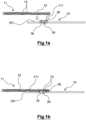
- THE figures 1a and 1b illustrate an assembly according to the present invention between a first part 10, made of a metallic material, and a second part 11, made of a composite material.
- the composite material of the second part 11 comprises at least one matrix 12, in particular a polymer, and fibers 13 arranged inside the matrix 12.
- the first part 10, or metal part 10, comprises at least one contact face 101.
- the second part 11, or composite part 11, comprises at least one contact face 111.
- the metal part 10 and the part composite 11 are intended to be assembled along their side contact 101, 111 overlapping with each other.
- the metal part 10 is thus intended to come into contact with the composite part 11 via its contact face 101; and the composite part 11 is intended to come into contact with the metal part 10 via its contact face 111.
- the metal part 10 comprises a plurality of teeth 16 projecting from the contact face 101 of the metal part 10.
- the teeth 16 project in a direction perpendicular to the contact face. contact 101 of the metal part 10.
- interstitial space 17 is in particular intended to allow the passage of the fibers 13 of the composite part 11.
- the tooth 16 advantageously has an extremal protrusion 20 suitable for retaining the fibers 13 inside the interstitial space 17 immediately adjacent.
- the extremal protrusion 20 thus forms a retaining means advantageously located at one the free end of the tooth 16, arranged opposite a base of the tooth 16 in connection with the contact face 101 of the metal part 10.
- the tooth 16 extends in a direction of extension of the tooth from the base towards the free end of the latter.
- the extremal protrusion 20 is made to minimize the loss of volume to avoid decompaction of the composite material of the composite part 11.
- a shape in the tools to promote compaction a first tool is shaped to press the fibers 13 against the metal part 10 and a second tool is shaped to limit as much as possible the creep of the matrix of the composite part 11 inside an opening 24 described more in detail below.
- each tooth 16 has circumferential protrusions 21.
- the circumferential protrusions 21 correspond to a local widening of the tooth 16.
- tooth 16 comprises circumferential protuberances 21 extending circumferentially on either side of tooth 16.
- the tooth 16 has a greater width on the side of their free end than in their central part.
- a width of the interstitial space 17 between two teeth 16 tends to decrease when moving from the central part of the interstitial space 17 towards an upper opening of the interstitial space 17 located on the side of the free end of teeth 16.
- the teeth 16 come from an edge of a through opening 24 made in the metal part 10. This edge is located in the thickness of the part 10.
- the matrix 12 of the composite material comes to flow into the through opening 24 of the metal part 10.
- the flow of the matrix 12 of the composite material into the opening crossing 24 of the metal part 10 makes it possible to reinforce the connection between the metal part 10 and the composite part 11.
- the teeth 16 come from an edge delimiting the through opening 24 of the metal part 10.
- the teeth 16 are angularly spaced from each other in a regular manner along a circumference of the through opening 24 of the metal part 10. Such a distribution of the teeth 16 allows transmission of forces normal and tangential 360 degrees.
- the teeth 16 are advantageously arranged symmetrically, so that there is a rotational invariance of the pattern formed by the teeth 16. More precisely, the rotational invariance is observable when the pattern is rotated. 'an angle equal to 360 degrees divided by the number of teeth, equal to 6 according to the example presented in figure 2 .
- the number of teeth 16, and therefore the order of the invariance in rotation of the pattern may vary and be adapted according to the application and, in particular, the level of the forces to be supported.
- the free end of the tooth 16 can end in a point 22.
- the pointed shape 22 of the tooth 16 makes it possible to improve the penetration of the tooth 16 inside the composite material, in particular inside the spaces between the fibers 13 of the composite material.
- the external diameter L1 can be of the order of 12.5mm plus or minus 0.5mm and/or the internal diameter L2 can be of the order of 4.5mm plus or minus 0.5mm.
- the minimum width L3 can be of the order of 1 mm plus or minus 0.5 mm and/or the maximum width L4 can be of the order of 2.7 mm plus or minus 0.5 mm.
- the minimum width L5 can be between 1 and 20 times, preferably between 1 and 5 times
- an average diameter of the fibers 13 of the composite material of the second part 11 and/or the maximum width L6 can be between 1 and 100 times, preferably between 1 and 10 times, the diameter of the fibers 13 of the composite material of the second part 11.
- the minimum width L5 of the interstitial space 17 may be of the order of 1 mm plus or minus 0.5 mm and/or the maximum width L6 of the interstitial space 17 may be of the order of 2 mm, plus or less 1mm.
- a height of tooth 16 is substantially equal to or slightly less than a thickness of composite part 11.
- the matrix 12 of the composite material of the second part 11 is made of a polymer material, in particular a thermoplastic polymer material, in particular of thermoplastic polycarbonate, of PPS (phenylene polysulphide), of PEEK (polyetheretherketone), of PEI ( polyetherimide), or polyamide.
- the matrix 12 of the composite material of the second part 11 could however be made of a thermosetting polymer material.
- the composite material of the second piece 11 comprises fibers 13, in particular of the satin type, for example of the 8H satin weave, twill or taffeta type, arranged in a mesh of fibers in which the fibers 13 are interlaced with each other, as this is illustrated on the figure 4 .
- the satin type for example of the 8H satin weave, twill or taffeta type
- first set of fibers 13a in which the fibers 13 are advantageously parallel to each other
- second set of fibers 13b in which the fibers 13 are advantageously parallel to each other. and/or perpendicular to the fibers of the first set of fibers 13a.
- four layers of fibers 13 are used, for example having a thickness of 0.5 mm, ie a total thickness of 2 mm.
- the fibers 13 may be in a knitted, woven or nonwoven arrangement. In the case where the fibers are woven, all weaves can be used.
- the metal part 10 could, for example, be an aluminum part having the advantage of being easily deformable to achieve the desired shapes.
- a first step 201, or forming step 201 the teeth 16 and/or the through opening 24 of the metal part 10 are made, for example, by stamping, 3D punching, 2D or laser punching, and/or stamping .
- the first step 201 makes it possible to form the teeth 16 so that they protrude with respect to the contact face 101 of the metal part 10.
- the composite part 11 is heated until it reaches a temperature tf situated between a glass transition temperature and a melting temperature of the composite material.
- the temperature tf is for example obtained at a time t1
- the temperature tf is such that the composite material, in particular the matrix, is sufficiently softened to be penetrated by the teeth 16.
- the temperature tf which depends on the composite material, is generally above 200°C.
- the heating step 202 may be carried out by means of an oven, by infrared, ultrasound, or induction, or using an oven.
- a third step 203, or pressing step 203 makes it possible to ensuring the penetration of the teeth 16 inside the spaces between the fibers 13 of the composite part 11, so that the fibers 13 of the composite material are inserted inside the interstitial spaces 17.
- the matrix 12 flows so as to fill the interstitial spaces 17 and the opening 24 during compression .
- the pressing step 203 is, for example, carried out under a pressure advantageously between 5 and 10 bars.
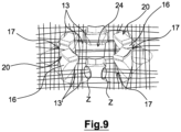
- the penetration of the teeth 16 inside the spaces between the fibers 13 of the composite part 11 has the consequence that the fibers 13 have moved relative to each other and are grouped together and concentrated locally in zones Z located in edge of teeth 16.
- the same fiber such as the fibers referenced 13 'on the figure 9 , can interact with several teeth 16 (three teeth in the example shown) which therefore participate in a mechanical restraint.
- a fourth step 204 makes it possible to consolidate the assembly between the metal part 10 and the composite part 11.
- the cooling step 204 is very short to obtain a rigid assembly.
- the duration of the cooling step can thus for example be less than 30 seconds.
- the cooling step 204 is implemented while maintaining an application pressure, in particular identical to that exerted during the pressing step 203.
- the matrix 12 is made of a thermosetting polymer material, it is possible to eliminate the heating step 202 and/or the cooling step 204 of the composite part 11.
- the mechanical strength obtained by virtue of the method according to the present invention is equivalent to or greater than that of an assembly by gluing or riveting.
- the metal part 10 and the composite part 11 are aircraft seat parts.
- the teeth 16 are made in a so-called point configuration, that is to say they come from an inner edge of a through opening 24 of small diameter made in the metal part 10.
- the teeth 16 extend along a zone, in particular linear.
- the teeth 16 in this case come, by continuity of material, from a free end edge of the metal part 10 delimiting one side of the part 10.
- the end edge carrying the teeth 16 extends in the thickness of the part 10 and forms a non-zero angle with the contact face 101.
- the edge of the metal part 10 is straight but it could as a variant have any shape.
- the teeth 16 are regularly spaced from each other.
- the interstitial spaces 17 are advantageously configured in the same way as before to retain the fibers 13 between the teeth 16.
- the teeth 16 extend along a surface of the metal part 10.
- the interstitial spaces 17 are configured in the same way as before to retain the fibers 13 between the teeth 16.
Landscapes
- Engineering & Computer Science (AREA)
- Mechanical Engineering (AREA)
- General Engineering & Computer Science (AREA)
- Physics & Mathematics (AREA)
- Thermal Sciences (AREA)
- Moulding By Coating Moulds (AREA)
- Laminated Bodies (AREA)
- Pressure Welding/Diffusion-Bonding (AREA)
Claims (13)
- Verfahren zur Montage eines ersten metallischen Teils (10) und eines zweiten Teils (11) aus einem Verbundwerkstoff mit mindestens einer Matrix (12) und innerhalb der Matrix (12) angeordneten Fasern (13),wobei das Verfahren mindestens umfasst:- einen Schritt (201) des Bildens des ersten Teils (10) durch Herstellen einer Mehrzahl von Zähnen (16), die von einer Kontaktfläche (101) des ersten Teils (10) vorstehen, wobei zwei benachbarte Zähne (16) durch einen Zwischenspalt (17) voneinander getrennt werden, wobei die Zähne (16) einen extremen Vorsprung (20) aufweisen, und- einen Schritt (203) des Pressens des zweiten Teils (11) gegen den ersten Teil (10),so dass die Fasern (13) des Verbundmaterials in die Zwischenspalte (17) zwischen benachbarten Zähnen (16) eindringen können und die Fasern (13) durch die extremen Vorsprünge der Zähne (16) zurückgehalten werden,gekennzeichnet, dass die Zähne (16) von einer Kante einer Durchgangsöffnung (24) in dem ersten Teil (10) kommen.
- Montageverfahren nach Anspruch 1, dadurch gekennzeichnet, dass es ferner umfasst:- einen Schritt (202) des Erhitzens des zweiten Teils (11) vor dem Pressschritt (203) und/oder- einen Kühlschritt (204) nach dem Pressschritt (204).
- Montageverfahren nach Anspruch 2, dadurch gekennzeichnet, dass der Kühlschritt (204) unter Druck durchgeführt wird.
- Anordnung mit einem ersten metallischen Teil (10) und einem zweiten Teil (11) aus einem Verbundwerkstoff mit mindestens einer Matrix (12) und innerhalb der Matrix (12) angeordneten Fasern (1, 3),- wobei der erste Teil (10) eine Mehrzahl von Zähnen (16), die von einer Basis in Verbindung mit einer Kontaktfläche (101) des ersten Teils (10) vorstehen, und ein freies Ende gegenüber der Basis mit einem extremen Vorsprung (20) umfasst, dadurch gekennzeichnet, dass die Zähne (16) von einem Rand einer Durchgangsöffnung (24) im ersten Teil (10) kommen.
- Anordnung nach Anspruch 4, dadurch gekennzeichnet, dass der Zahn (16) mindestens einen umlaufenden Vorsprung (21) aufweist.
- Anordnung nach Anspruch 5, dadurch gekennzeichnet, dass das freie Ende des Zahns (16) eine Breite (L4) aufweist, die größer als eine Breite (L3) eines mittleren Teils des Zahns (16) ist.
- Anordnung nach Anspruch 6, dadurch gekennzeichnet, dass die Breite (L3) des mittleren Teils des Zahns (16) geringer als eine Breite der Basis des Zahns (16) ist.
- Anordnung nach einem der Ansprüche 4 bis 7, dadurch gekennzeichnet, dass zwei benachbarte Zähne (16) durch einen Zwischenspalt (17) voneinander getrennt sind.
- Anordnung nach Anspruch 8, dadurch gekennzeichnet, dass der Zwischenspalt (17) am freien Ende des Zahns (16) eine Mindestbreite (L5) aufweist.
- Anordnung nach Anspruch 9, dadurch gekennzeichnet, dass der Zwischenspalt (17) in Erstreckungsrichtung des Zahns (16) mindestens eine Breitenverengung aufweist.
- Anordnung nach einem der Ansprüche 4 bis 10, dadurch gekennzeichnet, dass der erste Teil (10) eine Durchgangsöffnung (24) umfasst, und dass die Zähne (16) in regelmäßigen winkligen Abständen entlang eines Umfangs der Durchgangsöffnung (24) voneinander beabstandet sind.
- Anordnung nach einem der Ansprüche 4 bis 11, dadurch gekennzeichnet, dass der Zahn (16) durch eine Spitze (22) am freien Ende des Zahns (16) verlängert ist.
- Anordnung nach einem der Ansprüche 4 bis 12, dadurch gekennzeichnet, dass das erste Teil (10) und das zweite Teil (11) Teile eines Flugzeugsitzes sind.
Applications Claiming Priority (2)
| Application Number | Priority Date | Filing Date | Title |
|---|---|---|---|
| FR1770825A FR3069802B1 (fr) | 2017-08-03 | 2017-08-03 | Procede d'assemblage d'une piece metallique avec une piece composite et assemblage de pieces correspondant |
| PCT/EP2018/069079 WO2019025159A1 (fr) | 2017-08-03 | 2018-07-13 | Procédé d'assemblage d'une pièce métallique avec une pièce composite et assemblage de pièces correspondant |
Publications (2)
| Publication Number | Publication Date |
|---|---|
| EP3661733A1 EP3661733A1 (de) | 2020-06-10 |
| EP3661733B1 true EP3661733B1 (de) | 2023-06-14 |
Family
ID=60138644
Family Applications (1)
| Application Number | Title | Priority Date | Filing Date |
|---|---|---|---|
| EP18737636.3A Active EP3661733B1 (de) | 2017-08-03 | 2018-07-13 | Verfahren zum zusammenbau eines metallteils mit einem verbundteil und entsprechender zusammenbau von teilen |
Country Status (4)
| Country | Link |
|---|---|
| US (1) | US12060907B2 (de) |
| EP (1) | EP3661733B1 (de) |
| FR (1) | FR3069802B1 (de) |
| WO (1) | WO2019025159A1 (de) |
Families Citing this family (1)
| Publication number | Priority date | Publication date | Assignee | Title |
|---|---|---|---|---|
| JP7619217B2 (ja) * | 2021-09-07 | 2025-01-22 | 住友電装株式会社 | ワイヤハーネス |
Family Cites Families (21)
| Publication number | Priority date | Publication date | Assignee | Title |
|---|---|---|---|---|
| US304249A (en) * | 1884-08-26 | William w | ||
| US1854843A (en) * | 1931-06-04 | 1932-04-19 | Scovill Manufacturing Co | Carpet fastener |
| US2974378A (en) * | 1957-01-03 | 1961-03-14 | Ronel Corp | Metal fastener |
| US3090088A (en) * | 1962-05-07 | 1963-05-21 | Foley & Lavish Engineering Co | Connector device |
| US3529507A (en) * | 1969-03-19 | 1970-09-22 | Adams Co J D | Metal gusset plate |
| US3667337A (en) * | 1970-06-11 | 1972-06-06 | James Stanley Burke | Grip plate for wooden truss members |
| JPS59174015U (ja) * | 1983-05-09 | 1984-11-20 | スコービル・ジャパン株式会社 | スナツプフアスナ−のソケツト |
| US4679749A (en) * | 1984-09-28 | 1987-07-14 | Falcon Jet Corporation | Auxiliary airplane seats |
| US4679367A (en) * | 1985-08-29 | 1987-07-14 | Jack Walters & Sons, Corp. | Interconnecting of wooden members |
| US5312456A (en) * | 1991-01-31 | 1994-05-17 | Carnegie Mellon University | Micromechanical barb and method for making the same |
| US5788247A (en) * | 1996-12-12 | 1998-08-04 | Dana Corporation | Composite gasket comprising surface formed tangs |
| US20070261224A1 (en) * | 2006-05-11 | 2007-11-15 | Dow Global Technologies Inc. | Methods and articles in having a fringed microprotrusion surface structure |
| US20080003401A1 (en) * | 2006-06-28 | 2008-01-03 | Lockheed Martin Corporation | Metallic mini hooks for joining of metallic and composites |
| US7802799B1 (en) * | 2006-09-18 | 2010-09-28 | The United States Of America As Represented By The Administrator Of The National Aeronautics And Space Administration | Method of joining metallic and composite components |
| DE102009047671A1 (de) * | 2009-12-08 | 2011-06-09 | Airbus Operations Gmbh | Verfahren zum Anbinden eines Faserverbundbauteils an ein Strukturbauteil eines Luft- und Raumfahrzeuges und eine entsprechende Anordnung |
| WO2014064430A1 (en) * | 2012-10-22 | 2014-05-01 | Bae Systems Plc | Hybrid joint manufacutring |
| FR2998210B1 (fr) * | 2012-11-20 | 2017-03-10 | Plastic Omnium Cie | Ensemble d'un insert metallique et d'une nappe de materiau composite, procede d'incorporation d'un tel insert dans une telle nappe et piece obtenue par moulage d'une telle nappe |
| DE102013205745A1 (de) * | 2013-04-02 | 2014-10-02 | Bayerische Motoren Werke Aktiengesellschaft | Verfahren zur Herstellung einer Baugruppe sowie Baugruppe |
| DE102014107803A1 (de) * | 2014-06-03 | 2015-12-03 | Dr. Ing. H.C. F. Porsche Aktiengesellschaft | Kompositbauteil |
| FR3021899B1 (fr) | 2014-06-10 | 2016-07-15 | Inst De Rech Tech Jules Verne | Procede et dispositif d’assemblage metal - composite |
| CA3064506A1 (en) * | 2017-05-25 | 2018-11-29 | Penn Engineering & Manufacturing Corp. | Self-piercing fastener |
-
2017
- 2017-08-03 FR FR1770825A patent/FR3069802B1/fr active Active
-
2018
- 2018-07-13 EP EP18737636.3A patent/EP3661733B1/de active Active
- 2018-07-13 WO PCT/EP2018/069079 patent/WO2019025159A1/fr not_active Ceased
- 2018-07-13 US US16/636,262 patent/US12060907B2/en active Active
Also Published As
| Publication number | Publication date |
|---|---|
| FR3069802A1 (fr) | 2019-02-08 |
| FR3069802B1 (fr) | 2020-10-16 |
| US20200309176A1 (en) | 2020-10-01 |
| EP3661733A1 (de) | 2020-06-10 |
| WO2019025159A1 (fr) | 2019-02-07 |
| US12060907B2 (en) | 2024-08-13 |
Similar Documents
| Publication | Publication Date | Title |
|---|---|---|
| EP2709839B1 (de) | Versteifte doppelseitige verbundplatte sowie verfahren zur herstellung einer derartigen platte | |
| EP1951506B1 (de) | Verfahren zur herstellung eines gabelkopfs an einem aus verbundwerkstoff hergestellten strukturelement, insbesondere einer verbindungsstange | |
| EP1564141B1 (de) | Flugzeugsitzschiene und deren Fertigungsverfahren | |
| EP2416946B1 (de) | Verfahren zur herstellung einer aus einem thermoplastischen matrixverbundmaterial hergestellten versteiften platte und sich ergebende platte | |
| EP2665597B1 (de) | Mehrfach verzweigte fassung aus einem verbundmaterial und verfahren zur herstellung einer solchen mehrfach verzweigten fassung | |
| FR2915458A1 (fr) | Assemblage de panneaux de fuselage d'un avion | |
| EP3661733B1 (de) | Verfahren zum zusammenbau eines metallteils mit einem verbundteil und entsprechender zusammenbau von teilen | |
| CH711914B1 (fr) | Procédé pour fabriquer un boîtier de montre en fibres de carbone et boîtier de montre en fibres de carbone obtenu par ce procédé. | |
| EP2622232B1 (de) | Geriffelter haltewinkel aus einem verbundstoff | |
| EP3338988B1 (de) | Einsatz für trägerwerkstoff und entsprechender verbundteil | |
| EP2264324A1 (de) | Verfahren zur Herstellung einer Gelenkstange für den Flugzeugbau | |
| EP3152027B1 (de) | Verfahren zur herstellung eines zahnrades mit verstärkungsreifen | |
| EP1872932B1 (de) | Fasereinheit für Verbundteile, Verbundteil und Herstellungsverfahren eines solchen Verbundteils | |
| EP2576192B1 (de) | Einen flansch und gegenflansch bildende faserstruktur | |
| EP0736694B1 (de) | Unlösbare Rastverbindung | |
| EP2237944B1 (de) | Vorrichtung zur herstellung eines teils aus einem verbundstoff mit glättungsplatten mit gleitverbindungen und verfahren zur herstellung von glättungsplatten mit gleitverbindungen | |
| FR3108143A1 (fr) | Aube pour turbomachine comprenant une partie réalisée dans un matériau composite comprenant des fibres tissées en 3D | |
| EP2739448B1 (de) | Verfahren zum herstellen eines im wesentlichen dreieckigen verbundstoff-strukturteils | |
| EP1972421A1 (de) | Fasereinheit für Verbundwerkstück, Verbundwerkstück und Herstellungsverfahren eines solchen Verbundwerkstücks | |
| FR3081761A1 (fr) | Procede de fabrication d'une piece en matiere composite | |
| BE1016715A3 (fr) | Bielle. | |
| FR2764840A1 (fr) | Systeme d'assemblage pour des structures sandwichs composites renforcees par des fibres en construction modulaire | |
| FR3147607A1 (fr) | Assemblage comportant au moins une pièce composite et des moyens de fixation | |
| FR2983264A1 (fr) | Piece d'assemblage | |
| FR3063674A1 (fr) | Dispositif d'application de pression mecanique, procede d'impregnation et procede de collage |
Legal Events
| Date | Code | Title | Description |
|---|---|---|---|
| STAA | Information on the status of an ep patent application or granted ep patent |
Free format text: STATUS: UNKNOWN |
|
| STAA | Information on the status of an ep patent application or granted ep patent |
Free format text: STATUS: THE INTERNATIONAL PUBLICATION HAS BEEN MADE |
|
| PUAI | Public reference made under article 153(3) epc to a published international application that has entered the european phase |
Free format text: ORIGINAL CODE: 0009012 |
|
| STAA | Information on the status of an ep patent application or granted ep patent |
Free format text: STATUS: REQUEST FOR EXAMINATION WAS MADE |
|
| 17P | Request for examination filed |
Effective date: 20200116 |
|
| AK | Designated contracting states |
Kind code of ref document: A1 Designated state(s): AL AT BE BG CH CY CZ DE DK EE ES FI FR GB GR HR HU IE IS IT LI LT LU LV MC MK MT NL NO PL PT RO RS SE SI SK SM TR |
|
| AX | Request for extension of the european patent |
Extension state: BA ME |
|
| DAV | Request for validation of the european patent (deleted) | ||
| DAX | Request for extension of the european patent (deleted) | ||
| STAA | Information on the status of an ep patent application or granted ep patent |
Free format text: STATUS: EXAMINATION IS IN PROGRESS |
|
| 17Q | First examination report despatched |
Effective date: 20220912 |
|
| GRAP | Despatch of communication of intention to grant a patent |
Free format text: ORIGINAL CODE: EPIDOSNIGR1 |
|
| STAA | Information on the status of an ep patent application or granted ep patent |
Free format text: STATUS: GRANT OF PATENT IS INTENDED |
|
| INTG | Intention to grant announced |
Effective date: 20230403 |
|
| GRAS | Grant fee paid |
Free format text: ORIGINAL CODE: EPIDOSNIGR3 |
|
| GRAA | (expected) grant |
Free format text: ORIGINAL CODE: 0009210 |
|
| STAA | Information on the status of an ep patent application or granted ep patent |
Free format text: STATUS: THE PATENT HAS BEEN GRANTED |
|
| AK | Designated contracting states |
Kind code of ref document: B1 Designated state(s): AL AT BE BG CH CY CZ DE DK EE ES FI FR GB GR HR HU IE IS IT LI LT LU LV MC MK MT NL NO PL PT RO RS SE SI SK SM TR |
|
| REG | Reference to a national code |
Ref country code: CH Ref legal event code: EP |
|
| REG | Reference to a national code |
Ref country code: DE Ref legal event code: R096 Ref document number: 602018051837 Country of ref document: DE |
|
| REG | Reference to a national code |
Ref country code: AT Ref legal event code: REF Ref document number: 1578928 Country of ref document: AT Kind code of ref document: T Effective date: 20230715 |
|
| REG | Reference to a national code |
Ref country code: LT Ref legal event code: MG9D |
|
| REG | Reference to a national code |
Ref country code: NL Ref legal event code: MP Effective date: 20230614 |
|
| PG25 | Lapsed in a contracting state [announced via postgrant information from national office to epo] |
Ref country code: SE Free format text: LAPSE BECAUSE OF FAILURE TO SUBMIT A TRANSLATION OF THE DESCRIPTION OR TO PAY THE FEE WITHIN THE PRESCRIBED TIME-LIMIT Effective date: 20230614 Ref country code: NO Free format text: LAPSE BECAUSE OF FAILURE TO SUBMIT A TRANSLATION OF THE DESCRIPTION OR TO PAY THE FEE WITHIN THE PRESCRIBED TIME-LIMIT Effective date: 20230914 Ref country code: ES Free format text: LAPSE BECAUSE OF FAILURE TO SUBMIT A TRANSLATION OF THE DESCRIPTION OR TO PAY THE FEE WITHIN THE PRESCRIBED TIME-LIMIT Effective date: 20230614 |
|
| REG | Reference to a national code |
Ref country code: AT Ref legal event code: MK05 Ref document number: 1578928 Country of ref document: AT Kind code of ref document: T Effective date: 20230614 |
|
| PG25 | Lapsed in a contracting state [announced via postgrant information from national office to epo] |
Ref country code: RS Free format text: LAPSE BECAUSE OF FAILURE TO SUBMIT A TRANSLATION OF THE DESCRIPTION OR TO PAY THE FEE WITHIN THE PRESCRIBED TIME-LIMIT Effective date: 20230614 Ref country code: NL Free format text: LAPSE BECAUSE OF FAILURE TO SUBMIT A TRANSLATION OF THE DESCRIPTION OR TO PAY THE FEE WITHIN THE PRESCRIBED TIME-LIMIT Effective date: 20230614 Ref country code: LV Free format text: LAPSE BECAUSE OF FAILURE TO SUBMIT A TRANSLATION OF THE DESCRIPTION OR TO PAY THE FEE WITHIN THE PRESCRIBED TIME-LIMIT Effective date: 20230614 Ref country code: LT Free format text: LAPSE BECAUSE OF FAILURE TO SUBMIT A TRANSLATION OF THE DESCRIPTION OR TO PAY THE FEE WITHIN THE PRESCRIBED TIME-LIMIT Effective date: 20230614 Ref country code: HR Free format text: LAPSE BECAUSE OF FAILURE TO SUBMIT A TRANSLATION OF THE DESCRIPTION OR TO PAY THE FEE WITHIN THE PRESCRIBED TIME-LIMIT Effective date: 20230614 Ref country code: GR Free format text: LAPSE BECAUSE OF FAILURE TO SUBMIT A TRANSLATION OF THE DESCRIPTION OR TO PAY THE FEE WITHIN THE PRESCRIBED TIME-LIMIT Effective date: 20230915 |
|
| PG25 | Lapsed in a contracting state [announced via postgrant information from national office to epo] |
Ref country code: FI Free format text: LAPSE BECAUSE OF FAILURE TO SUBMIT A TRANSLATION OF THE DESCRIPTION OR TO PAY THE FEE WITHIN THE PRESCRIBED TIME-LIMIT Effective date: 20230614 |
|
| PG25 | Lapsed in a contracting state [announced via postgrant information from national office to epo] |
Ref country code: SK Free format text: LAPSE BECAUSE OF FAILURE TO SUBMIT A TRANSLATION OF THE DESCRIPTION OR TO PAY THE FEE WITHIN THE PRESCRIBED TIME-LIMIT Effective date: 20230614 |
|
| PG25 | Lapsed in a contracting state [announced via postgrant information from national office to epo] |
Ref country code: IS Free format text: LAPSE BECAUSE OF FAILURE TO SUBMIT A TRANSLATION OF THE DESCRIPTION OR TO PAY THE FEE WITHIN THE PRESCRIBED TIME-LIMIT Effective date: 20231014 |
|
| PG25 | Lapsed in a contracting state [announced via postgrant information from national office to epo] |
Ref country code: SM Free format text: LAPSE BECAUSE OF FAILURE TO SUBMIT A TRANSLATION OF THE DESCRIPTION OR TO PAY THE FEE WITHIN THE PRESCRIBED TIME-LIMIT Effective date: 20230614 Ref country code: SK Free format text: LAPSE BECAUSE OF FAILURE TO SUBMIT A TRANSLATION OF THE DESCRIPTION OR TO PAY THE FEE WITHIN THE PRESCRIBED TIME-LIMIT Effective date: 20230614 Ref country code: RO Free format text: LAPSE BECAUSE OF FAILURE TO SUBMIT A TRANSLATION OF THE DESCRIPTION OR TO PAY THE FEE WITHIN THE PRESCRIBED TIME-LIMIT Effective date: 20230614 Ref country code: PT Free format text: LAPSE BECAUSE OF FAILURE TO SUBMIT A TRANSLATION OF THE DESCRIPTION OR TO PAY THE FEE WITHIN THE PRESCRIBED TIME-LIMIT Effective date: 20231016 Ref country code: IS Free format text: LAPSE BECAUSE OF FAILURE TO SUBMIT A TRANSLATION OF THE DESCRIPTION OR TO PAY THE FEE WITHIN THE PRESCRIBED TIME-LIMIT Effective date: 20231014 Ref country code: EE Free format text: LAPSE BECAUSE OF FAILURE TO SUBMIT A TRANSLATION OF THE DESCRIPTION OR TO PAY THE FEE WITHIN THE PRESCRIBED TIME-LIMIT Effective date: 20230614 Ref country code: CZ Free format text: LAPSE BECAUSE OF FAILURE TO SUBMIT A TRANSLATION OF THE DESCRIPTION OR TO PAY THE FEE WITHIN THE PRESCRIBED TIME-LIMIT Effective date: 20230614 Ref country code: AT Free format text: LAPSE BECAUSE OF FAILURE TO SUBMIT A TRANSLATION OF THE DESCRIPTION OR TO PAY THE FEE WITHIN THE PRESCRIBED TIME-LIMIT Effective date: 20230614 |
|
| PG25 | Lapsed in a contracting state [announced via postgrant information from national office to epo] |
Ref country code: PL Free format text: LAPSE BECAUSE OF FAILURE TO SUBMIT A TRANSLATION OF THE DESCRIPTION OR TO PAY THE FEE WITHIN THE PRESCRIBED TIME-LIMIT Effective date: 20230614 |
|
| REG | Reference to a national code |
Ref country code: CH Ref legal event code: PL |
|
| PG25 | Lapsed in a contracting state [announced via postgrant information from national office to epo] |
Ref country code: MC Free format text: LAPSE BECAUSE OF FAILURE TO SUBMIT A TRANSLATION OF THE DESCRIPTION OR TO PAY THE FEE WITHIN THE PRESCRIBED TIME-LIMIT Effective date: 20230614 |
|
| REG | Reference to a national code |
Ref country code: DE Ref legal event code: R097 Ref document number: 602018051837 Country of ref document: DE |
|
| REG | Reference to a national code |
Ref country code: BE Ref legal event code: MM Effective date: 20230731 |
|
| PG25 | Lapsed in a contracting state [announced via postgrant information from national office to epo] |
Ref country code: LU Free format text: LAPSE BECAUSE OF NON-PAYMENT OF DUE FEES Effective date: 20230713 |
|
| PG25 | Lapsed in a contracting state [announced via postgrant information from national office to epo] |
Ref country code: MC Free format text: LAPSE BECAUSE OF FAILURE TO SUBMIT A TRANSLATION OF THE DESCRIPTION OR TO PAY THE FEE WITHIN THE PRESCRIBED TIME-LIMIT Effective date: 20230614 Ref country code: LU Free format text: LAPSE BECAUSE OF NON-PAYMENT OF DUE FEES Effective date: 20230713 |
|
| PLBE | No opposition filed within time limit |
Free format text: ORIGINAL CODE: 0009261 |
|
| STAA | Information on the status of an ep patent application or granted ep patent |
Free format text: STATUS: NO OPPOSITION FILED WITHIN TIME LIMIT |
|
| REG | Reference to a national code |
Ref country code: IE Ref legal event code: MM4A |
|
| PG25 | Lapsed in a contracting state [announced via postgrant information from national office to epo] |
Ref country code: DK Free format text: LAPSE BECAUSE OF FAILURE TO SUBMIT A TRANSLATION OF THE DESCRIPTION OR TO PAY THE FEE WITHIN THE PRESCRIBED TIME-LIMIT Effective date: 20230614 Ref country code: CH Free format text: LAPSE BECAUSE OF NON-PAYMENT OF DUE FEES Effective date: 20230731 |
|
| PG25 | Lapsed in a contracting state [announced via postgrant information from national office to epo] |
Ref country code: SI Free format text: LAPSE BECAUSE OF FAILURE TO SUBMIT A TRANSLATION OF THE DESCRIPTION OR TO PAY THE FEE WITHIN THE PRESCRIBED TIME-LIMIT Effective date: 20230614 |
|
| 26N | No opposition filed |
Effective date: 20240315 |
|
| PG25 | Lapsed in a contracting state [announced via postgrant information from national office to epo] |
Ref country code: SI Free format text: LAPSE BECAUSE OF FAILURE TO SUBMIT A TRANSLATION OF THE DESCRIPTION OR TO PAY THE FEE WITHIN THE PRESCRIBED TIME-LIMIT Effective date: 20230614 Ref country code: IT Free format text: LAPSE BECAUSE OF FAILURE TO SUBMIT A TRANSLATION OF THE DESCRIPTION OR TO PAY THE FEE WITHIN THE PRESCRIBED TIME-LIMIT Effective date: 20230614 Ref country code: BE Free format text: LAPSE BECAUSE OF NON-PAYMENT OF DUE FEES Effective date: 20230731 |
|
| PG25 | Lapsed in a contracting state [announced via postgrant information from national office to epo] |
Ref country code: IE Free format text: LAPSE BECAUSE OF NON-PAYMENT OF DUE FEES Effective date: 20230713 |
|
| PG25 | Lapsed in a contracting state [announced via postgrant information from national office to epo] |
Ref country code: IE Free format text: LAPSE BECAUSE OF NON-PAYMENT OF DUE FEES Effective date: 20230713 |
|
| PG25 | Lapsed in a contracting state [announced via postgrant information from national office to epo] |
Ref country code: BG Free format text: LAPSE BECAUSE OF FAILURE TO SUBMIT A TRANSLATION OF THE DESCRIPTION OR TO PAY THE FEE WITHIN THE PRESCRIBED TIME-LIMIT Effective date: 20230614 |
|
| PG25 | Lapsed in a contracting state [announced via postgrant information from national office to epo] |
Ref country code: BG Free format text: LAPSE BECAUSE OF FAILURE TO SUBMIT A TRANSLATION OF THE DESCRIPTION OR TO PAY THE FEE WITHIN THE PRESCRIBED TIME-LIMIT Effective date: 20230614 |
|
| PG25 | Lapsed in a contracting state [announced via postgrant information from national office to epo] |
Ref country code: CY Free format text: LAPSE BECAUSE OF FAILURE TO SUBMIT A TRANSLATION OF THE DESCRIPTION OR TO PAY THE FEE WITHIN THE PRESCRIBED TIME-LIMIT; INVALID AB INITIO Effective date: 20180713 |
|
| PG25 | Lapsed in a contracting state [announced via postgrant information from national office to epo] |
Ref country code: HU Free format text: LAPSE BECAUSE OF FAILURE TO SUBMIT A TRANSLATION OF THE DESCRIPTION OR TO PAY THE FEE WITHIN THE PRESCRIBED TIME-LIMIT; INVALID AB INITIO Effective date: 20180713 |
|
| PGFP | Annual fee paid to national office [announced via postgrant information from national office to epo] |
Ref country code: DE Payment date: 20250722 Year of fee payment: 8 |
|
| PGFP | Annual fee paid to national office [announced via postgrant information from national office to epo] |
Ref country code: GB Payment date: 20250724 Year of fee payment: 8 |
|
| PGFP | Annual fee paid to national office [announced via postgrant information from national office to epo] |
Ref country code: FR Payment date: 20250722 Year of fee payment: 8 |
|
| PG25 | Lapsed in a contracting state [announced via postgrant information from national office to epo] |
Ref country code: TR Free format text: LAPSE BECAUSE OF FAILURE TO SUBMIT A TRANSLATION OF THE DESCRIPTION OR TO PAY THE FEE WITHIN THE PRESCRIBED TIME-LIMIT Effective date: 20230614 |