EP3661777B1 - Rolloanordnung mit führungsbändern für rollobahn - Google Patents
Rolloanordnung mit führungsbändern für rollobahn Download PDFInfo
- Publication number
- EP3661777B1 EP3661777B1 EP18737540.7A EP18737540A EP3661777B1 EP 3661777 B1 EP3661777 B1 EP 3661777B1 EP 18737540 A EP18737540 A EP 18737540A EP 3661777 B1 EP3661777 B1 EP 3661777B1
- Authority
- EP
- European Patent Office
- Prior art keywords
- roller blind
- guide
- guide rails
- blind arrangement
- arrangement according
- Prior art date
- Legal status (The legal status is an assumption and is not a legal conclusion. Google has not performed a legal analysis and makes no representation as to the accuracy of the status listed.)
- Active
Links
Images


Classifications
-
- B—PERFORMING OPERATIONS; TRANSPORTING
- B60—VEHICLES IN GENERAL
- B60J—WINDOWS, WINDSCREENS, NON-FIXED ROOFS, DOORS, OR SIMILAR DEVICES FOR VEHICLES; REMOVABLE EXTERNAL PROTECTIVE COVERINGS SPECIALLY ADAPTED FOR VEHICLES
- B60J7/00—Non-fixed roofs; Roofs with movable panels, e.g. rotary sunroofs
- B60J7/0007—Non-fixed roofs; Roofs with movable panels, e.g. rotary sunroofs moveable head-liners, screens, curtains or blinds for ceilings
- B60J7/0015—Non-fixed roofs; Roofs with movable panels, e.g. rotary sunroofs moveable head-liners, screens, curtains or blinds for ceilings roller blind
-
- B—PERFORMING OPERATIONS; TRANSPORTING
- B60—VEHICLES IN GENERAL
- B60J—WINDOWS, WINDSCREENS, NON-FIXED ROOFS, DOORS, OR SIMILAR DEVICES FOR VEHICLES; REMOVABLE EXTERNAL PROTECTIVE COVERINGS SPECIALLY ADAPTED FOR VEHICLES
- B60J1/00—Windows; Windscreens; Accessories therefor
- B60J1/20—Accessories, e.g. wind deflectors, blinds
- B60J1/2011—Blinds; curtains or screens reducing heat or light intensity
- B60J1/2013—Roller blinds
- B60J1/2036—Roller blinds characterised by structural elements
- B60J1/2052—Guides
-
- B—PERFORMING OPERATIONS; TRANSPORTING
- B60—VEHICLES IN GENERAL
- B60J—WINDOWS, WINDSCREENS, NON-FIXED ROOFS, DOORS, OR SIMILAR DEVICES FOR VEHICLES; REMOVABLE EXTERNAL PROTECTIVE COVERINGS SPECIALLY ADAPTED FOR VEHICLES
- B60J7/00—Non-fixed roofs; Roofs with movable panels, e.g. rotary sunroofs
-
- B—PERFORMING OPERATIONS; TRANSPORTING
- B60—VEHICLES IN GENERAL
- B60J—WINDOWS, WINDSCREENS, NON-FIXED ROOFS, DOORS, OR SIMILAR DEVICES FOR VEHICLES; REMOVABLE EXTERNAL PROTECTIVE COVERINGS SPECIALLY ADAPTED FOR VEHICLES
- B60J1/00—Windows; Windscreens; Accessories therefor
- B60J1/20—Accessories, e.g. wind deflectors, blinds
- B60J1/2011—Blinds; curtains or screens reducing heat or light intensity
- B60J1/2013—Roller blinds
- B60J1/2036—Roller blinds characterised by structural elements
- B60J1/2041—Blind sheets, e.g. shape of sheets, reinforcements in sheets, materials therefor
-
- B—PERFORMING OPERATIONS; TRANSPORTING
- B60—VEHICLES IN GENERAL
- B60J—WINDOWS, WINDSCREENS, NON-FIXED ROOFS, DOORS, OR SIMILAR DEVICES FOR VEHICLES; REMOVABLE EXTERNAL PROTECTIVE COVERINGS SPECIALLY ADAPTED FOR VEHICLES
- B60J7/00—Non-fixed roofs; Roofs with movable panels, e.g. rotary sunroofs
- B60J7/02—Non-fixed roofs; Roofs with movable panels, e.g. rotary sunroofs of sliding type, e.g. comprising guide shoes
- B60J7/04—Non-fixed roofs; Roofs with movable panels, e.g. rotary sunroofs of sliding type, e.g. comprising guide shoes with rigid plate-like element or elements, e.g. open roofs with harmonica-type folding rigid panels
- B60J7/043—Sunroofs e.g. sliding above the roof
-
- E—FIXED CONSTRUCTIONS
- E06—DOORS, WINDOWS, SHUTTERS, OR ROLLER BLINDS IN GENERAL; LADDERS
- E06B—FIXED OR MOVABLE CLOSURES FOR OPENINGS IN BUILDINGS, VEHICLES, FENCES OR LIKE ENCLOSURES IN GENERAL, e.g. DOORS, WINDOWS, BLINDS, GATES
- E06B9/00—Screening or protective devices for wall or similar openings, with or without operating or securing mechanisms; Closures of similar construction
- E06B9/24—Screens or other constructions affording protection against light, especially against sunshine; Similar screens for privacy or appearance; Slat blinds
- E06B9/40—Roller blinds
- E06B9/42—Parts or details of roller blinds, e.g. suspension devices, blind boxes
-
- E—FIXED CONSTRUCTIONS
- E06—DOORS, WINDOWS, SHUTTERS, OR ROLLER BLINDS IN GENERAL; LADDERS
- E06B—FIXED OR MOVABLE CLOSURES FOR OPENINGS IN BUILDINGS, VEHICLES, FENCES OR LIKE ENCLOSURES IN GENERAL, e.g. DOORS, WINDOWS, BLINDS, GATES
- E06B9/00—Screening or protective devices for wall or similar openings, with or without operating or securing mechanisms; Closures of similar construction
- E06B9/56—Operating, guiding or securing devices or arrangements for roll-type closures; Spring drums; Tape drums; Counterweighting arrangements therefor
- E06B9/58—Guiding devices
Definitions
- the invention relates to a roller blind arrangement of a motor vehicle, in particular a vehicle roof, having the features of the preamble of patent claim 1.
- Such a blind arrangement is from the publication US 2017/0087966 A1 known and represents a side-guided roller blind that can be used as a shading arrangement of a vehicle roof, which has at least one transparent roof element, in particular a transparent sunroof cover.
- the known roller blind arrangement comprises a roller blind made of a flexible, windable material, which can be wound up to form a roller blind at a rear edge of a roof opening, which can be closed by means of the transparent cover element.
- the roller blind arrangement comprises two guide rails, each of which has a guide track in which a respective lateral guide band of the roller blind is guided.
- the two guide rails are part of a frame and are connected to one another via a frame transverse part, on which the roller blind roll is formed when the blind is wound up.
- the two guide rails are each formed from an aluminum extruded profile, whereas the frame cross-piece can be a plastic injection molded part.
- the roller blind arrangement includes a roller blind and lateral guide rails.
- a vehicle roller blind arrangement which has a roller blind web which is guided in guide rails via lateral guide strips.
- a sun visor device which has a roller blind that is guided in lateral slide rails.
- a sun blind for a motor vehicle roof is known, which is provided with a side guide for a roller blind.
- pamphlet WO 2014/191283 A3 teaches a shade assembly with a shade sheet having lateral guide straps that are guided in guide rails.
- a sunshade arrangement for a motor vehicle is known, which is designed in the manner of a roller blind arrangement with a roller blind guided on the side.
- pamphlet EP 2 447 098 A1 teaches a shade assembly for a vehicle roof with guide rails for a shade sheet.
- the invention is based on the object of creating a roller blind arrangement designed according to the type mentioned in the introduction, in which the roller blind web is centered before the guide strips enter the guide tracks of the guide rails.
- the guide rails each have a smoothly cut end face adjoining the frame cross-piece, as a result of which simple and inexpensive production of the guide rails made from extruded profiles is possible, and on the other hand that the frame cross-piece, which is connected to the guide rails, for each guide rail has a belt entry element, which forms an entry track for the guide belt in question, which is defined by at least one inner retaining rib relative to the longitudinal center plane and at least one outer retaining rib relative to the longitudinal center plane for the guide belt and which merges into the guide track of the relevant guide rail.
- a geometry for guiding a roller blind or fabric is integrated into the frame cross-piece, which allows the roller blind to be integrated into the frame cross-piece during assembly of the blind arrangement before it is connected to the guide rails.
- the guide rails can then be connected to the transverse frame part parallel to their longitudinal extent, usually in the longitudinal direction of the vehicle in the case of a vehicle roof.
- a mounting direction transverse to the extent of the guide rails is not required. This facilitates the assembly of the roller blind arrangement.
- the strip inlet elements are each connected via a retaining wall to a base body of the frame transverse part and the base body and the strip inlet elements are designed in one piece with the retaining walls as a plastic injection molded part.
- the retaining walls are deformable, in particular elastically deformable.
- the retaining walls each have a wavy cross-section in the longitudinal direction of the guide rails, which makes it possible to compensate for tolerances between the strip inlet elements and the guide rails, in particular in the longitudinal direction and in the vertical direction of the guide rails.
- the retaining walls have a maximum wall thickness of about 4 mm, so that by choosing an appropriate plastic, elastic deformability of the retaining walls is always guaranteed.
- the belt inlet elements each have at least one locking element which engages in the relevant guide rail.
- the locking element is a tab-like projection that rests against a wall or a web of the relevant guide rail.
- the locking element can be a pin, for example, and a receptacle corresponding to the pin can be formed on the guide rails. This makes it possible to position the strip inlet elements and the guide rails exactly in relation to each other.
- the locking element can be a latching element.
- a corresponding counter-locking element for the locking element can then be formed on the guide rails.
- the counter-locking element is, for example, a locking lug and/or a locking recess.
- latching of the latching elements on the mating latching elements provides direct feedback to a fitter as to whether the guide rails are correctly fixed to the belt inlet elements.
- the sealing element can be a butyl seal, which seals the water-conducting areas of the arrangement.
- the cross frame part of the roller blind arrangement is preferably a plastic injection molded part made of glass fiber reinforced plastic.
- the tape inlet element is preferably formed in one piece on the plastic injection molded part.
- the guide rails of the roller blind arrangement according to the invention are expediently each formed from an aluminum extruded profile. Before connecting to the frame cross member, the extruded aluminum profiles simply have to be cut off or cut to length.
- FIG 1 a vehicle roof 10 of a passenger car, otherwise not shown in detail, is shown, which has a roof cutout 12, which can be closed or at least partially released by means of a transparent cover element, not shown in detail here.
- the vehicle roof 10 has a shading device which is designed as a roller blind arrangement 14 from the one shown in FIGS Figures 1 to 8 a first embodiment is shown.
- the blind arrangement 14 forms a side-guided blind with a blind web 16 in the Area of a rear edge of the roof opening 12 can be wound up on a winding shaft 18 to form a roller blind roll 20 .
- the roller blind 16 is provided with a pull bow 22 which serves as an actuating element of the roller blind 16 .
- the roller blind arrangement 14 has a guide rail 24A or 24B on both sides in relation to a vertical longitudinal center plane of the roof, which extends along the respective side edge of the roof opening 12 .
- the guide rails 24A and 24B are each made of an aluminum material and each represent an extruded profile.
- the roller blind arrangement 14 also includes a transverse frame part 26 extending in the transverse direction of the roof, which runs along the rear edge of the roof opening 12 and connects the guide rails 24A and 24B arranged on both sides to one another.
- the guide rails 24A and 24B thus form, together with the frame cross-piece 26, a U-shaped roof frame.
- the frame cross member 26 is a plastic injection molded part made of glass fiber reinforced plastic.
- the roller blind arrangement 14 is essentially mirror-symmetrical in relation to a vertical longitudinal center plane of the roof, which is why in the following description reference is essentially only made to the roller blind arrangement areas on the left in relation to the forward direction of travel of the passenger vehicle.
- the areas of the roller blind arrangement that are arranged on the right in relation to the forward direction of travel of the passenger vehicle are designed accordingly and result in an analogous manner from the description.
- the first embodiment shown has the frame transverse part 26 on both sides in each case a bearing seat 28 for the winding shaft 18 .
- the transverse frame part 26 has a belt inlet element 30 adjoining the respective guide rail 24A or 24B, which adjoins the end face of the respective guide rail 24A or 24B that faces the transverse frame part 26 .
- Tape guide elements 30 each merge into a guide track 32 of the relevant guide rail 24A or 24B.
- the tape inlet elements 30 and the guideways 32 of the guide rails 24A and 24B serve to guide a guide strip 34 made of metal or plastic, by means of which the roller blind 16 is guided at its lateral edges relative to the vertical longitudinal center plane of the roof and is thus held taut in the transverse direction of the roof.
- the guide strips 34 are attached to the lateral edges of the roller blind 16 .
- the roller blind web is lifted off the guide belt 34 between the guide rail 24A and the roller blind roll 20 together with the pull bow 22 .
- the roller blind web 16 is guided and centered by the belt inlet elements 30 in the area of the frame transverse part 26.
- the strap inlet elements 30 each have an inner holding rib 36 and an outer holding rib 38 in relation to the vertical longitudinal center plane of the roof, which hold the guide strap 34 in question in the strap inlet element 30 and which attach to corresponding guide ribs 40 and 42 of the guide track 32 of the guide rail 24A or 24A in question .24B borders.
- the belt inlet elements 30 are each connected to a base body 46 of the frame transverse part 26 via a retaining wall 44.
- the retaining walls 44 each have a wall thickness of 2 mm to 4 mm and allow an offset of the belt inlet element 30 in question in the transverse direction of the roof.
- two tab-like projections 48 are formed on the end face of each strap inlet element 30, which in the installed position rest against a wall or rib of the relevant guide rail 24A or 24B and the relevant strap inlet element 30 secure against offset in the transverse direction of the roof.
- the base body 46 and the tape inlet elements 30 with the retaining walls 44 are designed in one piece as a plastic injection molded part and consist of a glass fiber reinforced plastic.
- the blind web 16, the guide tracks 32 and the tape inlet elements 30 of the blind arrangement are located in a dry area of the roof frame.
- a butyl seal formed sealing element 50 is arranged adjacent to the smoothly cut end faces or surfaces of the guide rails 24A and 24B .
- FIG. 9 to 12 a second embodiment of a roller blind arrangement according to the invention is shown, which is also part of a vehicle roof in figure 1 shown type is.
- this roller blind arrangement comprises a frame transverse part 26 which has a bearing mount 28 for a winding shaft 18 on both sides.
- a strip inlet element 30 is arranged adjacent to the guide rails 24A and 24B.
- the guide strips 34 are fastened to the lateral edges of the roller blind 16 and thus guide the roller blind 16 at its lateral edges relative to the vertical longitudinal center plane of the roof, as a result of which the roller blind 16 is tensioned in the transverse direction of the roof.
- the tape inlet elements 30 make it possible to guide and center the roller blind 16 in the area of the transverse frame part 26 .
- the belt inlet elements 30 arranged on both sides each have an inner holding rib 36 and an outer holding rib 38, with the holding ribs 36 and 38 holding the guide belt 34 in question in the respective belt inlet element 30 and in each case on corresponding guide ribs 40 and 42 of the guide track 32 of the relevant guide rail 24A or 24B.
- the belt inlet elements 30 each have a resilient element 64, which is particularly flexible in the longitudinal direction of the guide rail has a wavy cross-section, which is thus turned over several times in alternating directions. Tolerances between the strip inlet elements 30 and the relevant guide rail 24A or 24B can be compensated for by the resilient elements 64, with tolerances in the longitudinal direction and vertical direction of the guide rail being able to be compensated in particular.
- the tape inlet elements 30 each comprise two locking elements in the form of pins 52 and 54.
- Recesses 66 and 68 corresponding to the pins 52 and 54 are configured on the guide rails 24A and 24B by means of a corresponding profile design .
- the pins 52 and 54 are each arranged in the corresponding recesses 66 and 68 of the relevant guide rails 24A, 24B.
- the guide rails 24A and 24B are thus each positioned exactly opposite to the strip inlet elements 30, ie there is a defined relative position.
- the tape inlet elements 30 each include two locking elements 56 and 58 designed as locking elements.
- the guide rails 24A and 24B each have a locking counter-element 60 in the form of a recess and a locking counter-element 62 in the form of a locking lug. With the aid of the latching elements 56 and 58 and the mating latching elements 60 and 62, it is possible to fix the guide rails 24A and 24B to the tape inlet elements 30.
Landscapes
- Engineering & Computer Science (AREA)
- Mechanical Engineering (AREA)
- Structural Engineering (AREA)
- Architecture (AREA)
- Civil Engineering (AREA)
- Operating, Guiding And Securing Of Roll- Type Closing Members (AREA)
Description
- Die Erfindung betrifft eine Rolloanordnung eines Kraftfahrzeuges, insbesondere eines Fahrzeugdachs, mit den Merkmalen des Oberbegriffs des Patentanspruchs 1.
- Eine derartige Rolloanordnung ist aus der Druckschrift
US 2017/0087966 A1 bekannt und stellt ein seitengeführtes Rollo dar, das als Beschattungsanordnung eines Fahrzeugdachs eingesetzt werden kann, das mindestens ein transparentes Dachelement, insbesondere einen transparenten Schiebedachdeckel aufweist. Die bekannte Rolloanordnung umfasst eine Rollobahn aus einem flexiblen, aufwickelbaren Material, die an einem heckseitigen Rand einer Dachöffnung, die mittels des transparenten Deckelelements verschließbar ist, zu einem Rollowickel aufwickelbar ist. Um die Rollobahn an ihren Seitenrändern führen zu können, umfasst die Rolloanordnung zwei Führungsschienen, die jeweils eine Führungsbahn aufweisen, in der ein jeweiliges seitliches Führungsband der Rollobahn geführt ist. Die beiden Führungsschienen sind Bestandteil eines Rahmens und über ein Rahmenquerteil miteinander verbunden, an dem sich der Rollowickel beim Aufwickeln des Rollos ausbildet. Die beiden Führungsschienen sind in der Regel jeweils aus einem Aluminiumstrangpressprofil gebildet, wohingegen das Rahmenquerteil ein Kunststoffspritzgießteil sein kann. Wenn die Rollobahn zum Beschatten des transparenten Dachabschnitts von ihrem Rollowickel abgewickelt wird, laufen die Führungsbänder in die zugeordneten Führungsbahnen der Führungsschienen ein. Beim Aufwickeln zu dem Rollowickel laufen die von den Führungsbändern gebildeten Ränder der Rollobahn aus den Führungsbahnen der Führungsschienen aus. Die Führungsbahnen sind oben jeweils durch Führungsrippen begrenzt, welche das jeweilige Führungsband in der betreffenden Führungsbahn hält. Zudem erfolgt durch die in den Führungsbahnen gehaltenen Führungsbänder eine Zentrierung der Rollobahn in Rolloquerrichtung. - Aus der Druckschrift
DE 20 2007 001 909 U1 ist eine Rolloanordnung für ein Kraftfahrzeug bekannt, die eine Rollobahn mit einer Seitenführung aufweist. - Aus der Druckschrift
DE 10 2007 041 298 A1 ist eine Rolloanordnung für ein Kraftfahrzeug bekannt, die eine Rollobahn mit einer Seitenführung aufweist. - Aus der Druckschrift
DE 10 2007 002 857 A1 ist eine Rolloanordnung für eine Fensteröffnung eines Kraftfahrzeugs bekannt. Die Rolloanordnung umfasst eine Rollobahn und seitliche Führungsschienen. - Aus der Druckschrift
DE 10 2011 113 207 A1 ist eine Fahrzeugrolloanordnung bekannt, die eine Rollobahn aufweist, die über seitliche Führungsbänder in Führungsschienen geführt ist. - Aus der Druckschrift
DE 10 2006 003 983 A1 ist eine Sonnenblenden-Vorrichtung bekannt, welche eine Rollobahn aufweist, die in seitlichen Gleitschienen geführt ist. Aus der DruckschriftDE 197 39 919 A1 ist ein Sonnenrollo für ein Kraftfahrzeugdach bekannt, das mit einer Seitenführung für eine Rollobahn versehen ist. - Druckschrift
WO 2014/191283 A3 lehrt eine Rolloanordnung mit einer Rollobahn, die seitliche Führungsbänder aufweist, die in Führungsschienen geführt sind. - Aus der Druckschrift
DE 10 2012 201 256 A1 ist eine Sonnenschutzanordnung für ein Kraftfahrzeug bekannt, die nach Art einer Rolloanordnung mit einem seitengeführten Rollo ausgebildet ist. - Druckschrift
EP 2 447 098 A1 lehrt eine Rolloanordnung für ein Fahrzeugdach mit Führungsschienen für eine Rollobahn. - Aus der Druckschrift
DE 10 2010 054 590 B3 ist ein Rahmen eines öffnungsfähigen-Fahrzeugdachs bekannt, an dem ein Beschattungselement geführt werden kann. - Aus der Druckschrift
EP 2 580 077 B1 ist ein Fahrzeugfenster mit integriertem Rollo und einer Seitenführung für das Rollo bekannt. - Der Erfindung liegt die Aufgabe zugrunde, eine gemäß der einleitend genannten Gattung ausgebildete Rolloanordnung zu schaffen, bei der eine Zentrierung der Rollobahn schon vor dem Einlaufen der Führungsbänder in die Führungsbahnen der Führungsschienen erfolgt.
- Diese Aufgabe ist erfindungsgemäß durch die Rolloanordnung mit den Merkmalen des Patentanspruchs 1 gelöst.
- Gemäß der vorliegenden Erfindung wird also vorgeschlagen, dass einerseits die Führungsschienen jeweils eine glatt geschnittene, an das Rahmenquerteil grenzende Stirnseite haben, wodurch eine einfache und kostengünstige Herstellung der aus Strangpressprofilen gefertigten Führungsschienen möglich ist, und andererseits das Rahmenquerteil, das mit den Führungsschienen verbunden ist, für jede Führungsschiene ein Bandeinlaufelement aufweist, das eine Einlaufbahn für das betreffende Führungsband bildet, die durch mindestens eine bezogen auf die Längsmittelebene innere Halterippe und mindestens eine bezogen auf die Längsmittelebene äußere Halterippe für das Führungsband definiert ist und die in die Führungsbahn der betreffenden Führungsschiene übergeht. Damit ist eine Geometrie für eine Rollobahn- bzw. Stoffführung in das Rahmenquerteil integriert, die es ermöglicht, dass die Rollobahn bei der Montage der Rolloanordnung in das Rahmenquerteil integriert wird, bevor dieses mit den Führungsschienen verbunden wird. Die Führungsschienen können dann parallel zu ihrer Längserstreckung, bei einem Fahrzeugdach in der Regel in Fahrzeuglängsrichtung, mit dem Rahmenquerteil verbunden werden. Eine Montagerichtung quer zur Erstreckung der Führungsschienen ist nicht erforderlich. Dies erleichtert die Montage der Rolloanordnung.
- Bei der Rolloanordnung nach der Erfindung sind die Bandeinlaufelemente jeweils über eine Haltewand mit einem Grundkörper des Rahmenquerteils verbunden und der Grundkörper und die Bandeinlaufelemente mit den Haltewänden in einstückiger Weise als Kunststoffspritzgießteil ausgebildet.
- Bei einer zweckmäßigen Ausführungsform der Rolloanordnung nach der Erfindung sind die Haltewände verformbar, insbesondere elastisch verformbar. Durch Verformung der Haltewände kann ein Toleranzausgleich zwischen den Bandeinlaufelementen und den Führungsschienen erreicht werden.
- Bei einer bevorzugten Ausführungsform haben die Haltewände in Führungsschienenlängsrichtung jeweils einen wellenförmigen Querschnitt, der es ermöglicht Toleranzen zwischen den Bandeinlaufelementen und den Führungsschienen, insbesondere in Führungsschienenlängsrichtung und in Führungsschienenhochrichtung, auszugleichen.
- Beispielsweise haben die Haltewände eine maximale Wandstärke von etwa 4 mm, so dass durch Wahl eines entsprechenden Kunststoffs stets eine elastische Verformbarkeit der Haltewände gewährleistet ist.
- Um die Position der Bandeinlaufelemente an den Führungsschienen eindeutig zu definieren, weisen die Bandeinlaufelemente bei einer bevorzugten Ausführungsform der Rolloanordnung nach der Erfindung jeweils mindestens ein Arretierelement auf, das in die betreffende Führungsschiene eingreift. Beispielsweise ist das Arretierelement ein laschenartiger Vorsprung, der an einer Wand oder einem Steg der betreffenden Führungsschiene anliegt.
- Das Arretierelement kann beispielsweise ein Stift sein und an den Führungsschienen kann jeweils eine dem Stift entsprechende Aufnahme ausgebildet sein. Dies ermöglicht es, die Bandeinlaufelemente und die Führungsschienen jeweils exakt zueinander zu positionieren.
- Bei einer alternativen Ausführungsform kann das Arretierelement ein Rastelement sein. An den Führungsschienen kann dann jeweils ein korrespondierendes Rastgegenelement für das Rastelement ausgebildet sein. Das Rastgegenelement ist beispielsweise eine Rastnase und/oder eine Rastausnehmung.
- Hierdurch sind bei einer Montage keine zusätzlichen Bauteile zur Fixierung der Führungsschienen an den Bandeinlaufelementen erforderlich. Zudem gibt ein Verrasten der Rastelemente an den Rastgegenelementen eine direkte Rückmeldung an einen Monteur, ob die Führungsschienen korrekt an den Bandeinlaufelementen fixiert sind.
- Um Übergangsbereiche zwischen den Führungsschienen und dem Rahmenquerteil abzudichten, der im Nassbereich des betreffenden Fahrzeugs liegt, ist bei einer zweckmäßigen Ausführungsform der Rolloanordnung nach der Erfindung zwischen den glatt geschnittenen Stirnseiten der Führungsschienen und dem Rahmenquerteil jeweils ein Dichtelement angeordnet. Das Dichtelement kann eine Butyl-Dichtung sein, welche die wasserführenden Bereiche der Anordnung abdichtet.
- Das Rahmenquerteil der Rolloanordnung ist vorzugsweise ein Kunststoffspritzgießteil aus glasfaserverstärktem Kunststoff. Das Bandeinlaufelement ist vorzugsweise einstückig an dem Kunststoffspritzgießteil ausgebildet.
- Die Führungsschienen der Rolloanordnung nach der Erfindung sind zweckmäßigerweise jeweils aus einem Aluminiumstrangpressprofil gebildet. Vor dem Anbinden an das Rahmenquerteil müssen die Aluminiumstrangpressprofile nur in einfacher Weise glatt abgeschnitten bzw. abgelängt werden.
- Weitere Vorteile und vorteilhafte Ausgestaltungen des Gegenstandes der Erfindung sind der Beschreibung, der Zeichnung und den Patentansprüchen entnehmbar.
- Zwei Ausführungsbeispiele einer Rolloanordnung nach der Erfindung sind in der Zeichnung schematisch vereinfacht dargestellt und werden in der nachfolgenden Beschreibung näher erläutert. Es zeigt:
- Figur 1
- eine perspektivische Draufsicht auf ein Fahrzeugdach mit einer Rolloanordnung nach der Erfindung;
- Figur 2
- eine vergrößerte Ansicht der ersten Ausführungsform der Rolloanordnung in einem Bereich II in
Figur 1 ; - Figur 3
- eine
Figur 2 entsprechende Ansicht der ersten Ausführungsform der Rolloanordnung, jedoch ohne Darstellung einer Rollobahn; - Figur 4
- eine Draufsicht auf den in
Figur 3 dargestellten Bereich der ersten Ausführungsform der Rolloanordnung; - Figur 5
- eine Draufsicht auf ein Rahmenquerteil der ersten Ausführungsform der Rolloanordnung im Bereich eines Bandeinlaufelements;
- Figur 6
- eine perspektivische Darstellung des Bandeinlaufelements der ersten Ausführungsform der Rolloanordnung;
- Figur 7
- einen Schnitt durch die erste Ausführungsform der Rolloanordnung entlang der Linie VII-VII in
Figur 2 ; - Figur 8
- einen Schnitt durch die erste Ausführungsform der Rolloanordnung entlang der Linie VIII-VIII in
Figur 2 ; - Figur 9
- eine vergrößerte Ansicht einer zweiten Ausführungsform einer Rolloanordnung in einem Bereich II in
Figur 1 , jedoch in einem VormontageZustand; - Figur 10
- eine perspektivische Unteransicht des in
Figur 9 dargestellten Bereichs der zweiten Ausführungsform der Rolloanordnung im VormontageZustand; - Figur 11
- eine Draufsicht auf den in
Figur 9 dargestellten Bereich der zweiten Ausführungsform der Rolloanordnung im Vormontage-Zustand; - Figur 12
- ein Schnitt durch die zweite Ausführungsform der Rolloanordnung entlang der Linie XII-XII in
Figur 11 . - Figur 13
- eine Draufsicht auf den in
Figur 9 dargestellten Bereich der zweiten Ausführungsform der Rolloanordnung im montierten Zustand; - Figur 14
- ein Schnitt durch die zweite Ausführungsform der Rolloanordnung im montierten Zustand entlang der Linie XIV-XIV in
Figur 13 . - In
Figur 1 ist ein Fahrzeugdach 10 eines ansonsten nicht näher dargestellten Personenkraftwagens gezeigt, das einen Dachausschnitt 12 aufweist, welcher mittels eines hier nicht näher dargestellten, transparenten Deckelelements geschlossen oder zumindest teilweise freigegeben werden kann. - Um einen Fahrzeuginnenraum des Personenkraftwagens vor durch den Dachausschnitt bzw. das transparente Deckelelement einfallendem Licht schützen zu können, weist das Fahrzeugdach 10 eine Beschattungseinrichtung auf, die als Rolloanordnung 14 ausgebildet ist von der in den
Figuren 1 bis 8 eine erste Ausführungsform dargestellt ist. Die Rolloanordnung 14 bildet ein seitengeführtes Rollo mit einer Rollobahn 16, die im Bereich eines heckseitigen Randes des Dachausschnitts 12 auf einer Wickelwelle 18 zu einem Rollowickel 20 aufwickelbar ist. An ihrem dem Rollowickel 20 abgewandten, sich in Dachquerrichtung erstreckenden Rand ist die Rollobahn 16 mit einem Zugspriegel 22 versehen, der als Betätigungselement der Rollobahn 16 dient. - Zur Seitenführung der Rollobahn 16 weist die Rolloanordnung 14 bezogen auf eine vertikale Dachlängsmittelebene beidseits jeweils eine Führungsschiene 24A bzw. 24B auf, die sich entlang des jeweiligen Seitenrandes des Dachausschnitts 12 erstreckt. Die Führungsschienen 24A und 24B sind jeweils aus einem Aluminiumwerkstoff gefertigt und stellen jeweils ein Strangpressprofil dar. Der Zugspriegel 22 ist über Gleiter 23 in den Führungsschienen 24A und 24B geführt.
- Die Rolloanordnung 14 umfasst des Weiteren ein sich in Dachquerrichtung erstreckendes Rahmenquerteil 26, das entlang des heckseitigen Randes des Dachausschnitts 12 verläuft und die beidseits angeordneten Führungsschienen 24A und 24B miteinander verbindet. Die Führungsschienen 24A und 24B bilden damit zusammen mit dem Rahmenquerteil 26 einen U-förmigen Dachrahmen. Das Rahmenquerteil 26 ist ein Kunststoffspritzgießteil aus glasfaserverstärktem Kunststoff.
- Die Rolloanordnung 14 ist bezogen auf eine vertikale Dachlängsmittelebene im wesentlichen spiegelsymmetrisch ausgebildet, weshalb in der nachfolgenden Beschreibung im Wesentlichen nur auf die bezogen auf die Vorwärtsfahrtrichtung des Personenkraftwagens links angeordneten Rolloanordnungsbereiche Bezug genommen wird. Die bezogen auf die Vorwärtsfahrtrichtung des Personenkraftwagens rechts angeordneten Bereiche der Rolloanordnung sind entsprechend ausgebildet und ergeben sich in analoger Weise aus der Beschreibung.
- Bei der in den
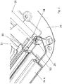
Figuren 2 bis 8 dargestellten ersten Ausführungsform weist das Rahmenquerteil 26 beidseits jeweils eine Lageraufnahme 28 für die Wickelwelle 18 auf. Zudem weist das Rahmenquerteil 26 angrenzend an die jeweilige Führungsschiene 24A bzw. 24B jeweils ein Bandeinlaufelement 30 auf, welches an die dem Rahmenquerteil 26 zugewandte Stirnseite der jeweiligen Führungsschiene 24A bzw. 24B grenzt. Bandführungselemente 30 gehen jeweils in eine Führungsbahn 32 der betreffenden Führungsschiene 24A bzw. 24B über. Die Bandeinlaufelemente 30 und die Führungsbahnen 32 der Führungsschienen 24A und 24B dienen dazu, jeweils ein Führungsband 34 aus Metall oder Kunststoff zu führen, mittels dessen die Rollobahn 16 an ihren bezogen auf die vertikale Dachlängsmittelebene seitlichen Rändern geführt und somit in Dachquerrichtung gespannt gehalten ist. Die Führungsbänder 34 sind an den seitlichen Rändern der Rollobahn 16 befestigt. InFigur 2 ist die Rollobahn der Anschaulichkeit halber zwischen der Führungsschiene 24A und dem Rollowickel 20 zusammen mit dem Zugspriegel 22 von dem Führungsband 34 abgehoben. Durch die Bandeinlaufelemente 30 erfolgt die Führung und Zentrierung der Rollobahn 16 schon im Bereich des Rahmenquerteils 26. - Wie insbesondere den
Figuren 5 und 6 zu entnehmen ist, haben die Bandeinlaufelemente 30 jeweils bezogen auf die vertikale Dachlängsmittelebene eine innere Halterippe 36 und eine äußere Halterippe 38, welche das betreffende Führungsband 34 in dem Bandeinlaufelement 30 halten und welche an korrespondierende Führungsrippen 40 und 42 der Führungsbahn 32 der betreffenden Führungsschiene 24A bzw. 24B grenzen. - Um bei der Montage der Führungsschienen 24A und 24B einen Toleranzausgleich zwischen den Bandeinlaufelementen 30 und den zugeordneten Führungsbahnen 32 der Führungsschienen 24A und 24B realisieren zu können, sind die Bandeinlaufelemente 30 jeweils über eine Haltewand 44 mit einem Grundkörper 46 des Rahmenquerteils 26 verbunden. Die Haltewände 44 haben jeweils eine Wandstärke von 2 mm bis 4 mm und ermöglichen einen Versatz des betreffenden Bandeinlaufelements 30 in Dachquerrichtung.
- Zur positionsgenauen Anbindung der Bandeinlaufelemente 30 an die Führungsschienen 24A und 24B sind an jedem Bandeinlaufelement 30 stirnseitig zwei jeweils ein Arretierelement bildende laschenartige Vorsprünge 48 ausgebildet, welche in Einbaulage an einer Wand bzw. Rippe der betreffenden Führungsschiene 24A bzw. 24B anliegen und das betreffende Bandeinlaufelement 30 gegen einen Versatz in Dachquerrichtung sichern.
- Der Grundkörper 46 und die Bandeinlaufelemente 30 mit den Haltewänden 44 sind in einstückiger Weise als Kunststoffspritzgießteil ausgebildet und bestehen aus einem glasfaserverstärktem Kunststoff.
- Die Rollobahn 16, die Führungsbahnen 32 und die Bandeinlaufelemente 30 der Rolloanordnung liegen in einem Trockenbereich des Dachrahmens. Um in einem im Nassbereich des Dachrahmens liegenden Übergangsbereich zwischen den Führungsschienen 24A und 24B einerseits und dem Rahmenquerteil 26 andererseits ein Eindringen von Wasser in den Fahrzeugaufbau zu verhindern, ist angrenzend an die glatt geschnittenen Stirnseiten bzw. -flächen der Führungsschienen 24A und 24B jeweils ein aus einer Butyldichtung gebildetes Dichtungselement 50 angeordnet.
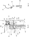
- In den
Figuren 9 bis 12 ist eine zweite Ausführungsform einer Rolloanordnung nach der Erfindung dargestellt, die ebenfalls Bestandteil eines Fahrzeugdachs der inFigur 1 dargestellten Art ist. Wie insbesondereFigur 9 zu entnehmen ist, umfasst diese Rolloanordnung ein Rahmenquerteil 26, das beidseits jeweils eine Lageraufnahme 28 für eine Wickelwelle 18 aufweist. Angrenzend an Führungsschienen 24A und 24B ist jeweils ein Bandeinlaufelement 30 angeordnet. - Die Bandeinlaufelemente 30, die Bestandteil des Rahmenquerteils 26 sind, gehen jeweils in eine Führungsbahn 32 der betreffenden Führungsschiene 24A bzw. 24B über. Die Bandeinlaufelemente 30 und die Führungsbahnen 32 der Führungsschienen 24A und 24B dienen dazu, ein Führungsband 34, welches aus Metall oder Kunststoff sein kann, zu führen. Die Führungsbänder 34 sind an den seitlichen Rändern der Rollobahn 16 befestigt und führen somit die Rollobahn 16 an ihren bezogen auf die vertikale Dachlängsmittelebene seitlichen Rändern, wodurch die Rollobahn 16 in Dachquerrichtung gespannt ist. Die Bandeinlaufelemente 30 ermöglichen es, die Rollobahn 16 schon im Bereich des Rahmenquerteils 26 zu führen und zu zentrieren.
- Bezogen auf die vertikale Dachlängsmittelebene weisen die beidseits angeordneten Bandeinlaufelemente 30 jeweils eine innere Halterippe 36 und eine äußere Halterippe 38 auf, wobei die Halterippen 36 und 38 das betreffende Führungsband 34 in dem jeweiligen Bandeinlaufelement 30 halten und jeweils an korrespondierende Führungsrippen 40 und 42 der Führungsbahn 32 der betreffenden Führungsschiene 24A bzw. 24B grenzen.
- An einer dem Rahmenquerteil 26 zugewandten Seite weisen die Bandeinlaufelemente 30 jeweils ein federndes Element 64 auf, das insbesondere in Führungsschienenlängsrichtung einen wellenförmigen Querschnitt aufweist, das also mehrfach wechselsinnig umgeschlagen ist. Durch die federnden Elemente 64 können Toleranzen zwischen den Bandeinlaufelementen 30 und der betreffenden Führungsschiene 24A bzw. 24B ausgeglichen werden, wobei insbesondere Toleranzen in Führungsschienenlängsrichtung und -hochrichtung ausgleichbar sind.
- Auf einer der jeweiligen Führungsschiene 24A bzw. 24B zugewandten Seite, umfassen die Bandeinlaufelemente 30 jeweils zwei Arretierlemente in Form von Stiften 52 und 54. An den Führungsschienen 24A und 24B sind jeweils durch entsprechende Profilausgestaltung zu den Stiften 52 und 54 korrespondierende Ausnehmungen 66 und 68 ausgestaltet. In einem in den
Figuren 13 und 14 dargestellten montierten Zustand sind die Stifte 52 und 54 jeweils in den korrespondierenden Ausnehmungen 66 und 68 der betreffenden Führungsschienen 24A, 24B angeordnet. Damit sind die Führungsschienen 24A und 24B jeweils exakt gegenüber zu den Bandeinlaufelementen 30 positioniert, d.h. es liegt eine definierte Relativlage vor. - Des Weiteren umfassen die Bandeinlaufelemente 30 jeweils zwei als Rastelemente ausgestaltete Arretierelemente 56 und 58. Die Führungsschienen 24A und 24B weisen jeweils ein Rastgegenelement 60 in Form einer Ausnehmung und ein Ratsgegenelement 62 in Form einer Rastnase auf. Mit Hilfe der Rastelemente 56 und 58 und der Rastgegenelemente 60 und 62 ist es möglich, die Führungsschienen 24A und 24B an den Bandeinlaufelementen 30 zu fixieren.
-
- 10
- Fahrzeugdach
- 12
- Dachausschnitt
- 14
- Rolloanordnung
- 16
- Rollobahn
- 18
- Wickelwelle
- 20
- Rollowickel
- 22
- Zugspriegel
- 23
- Gleiter
- 24A, B
- Führungsschiene
- 26
- Rahmenquerteil
- 28
- Lageraufnahme
- 30
- Bandeinlaufelement
- 32
- Führungsbahn
- 34
- Führungsband
- 36
- innere Halterippe
- 38
- äußere Halterippe
- 40
- Führungsrippe
- 42
- Führungsrippe
- 44
- Haltewand
- 46
- Grundkörper
- 48
- laschenartiger Vorsprung
- 50
- Dichtungselement
- 52
- Stift
- 54
- Stift
- 56
- Rastelement
- 58
- Rastelement
- 60
- Rastgegenelement
- 62
- Rastgegenelement
- 64
- Haltewand
- 66
- Ausnehmung
- 68
- Ausnehmung
Claims (11)
- Rolloanordnung eines Kraftfahrzeuges, insbesondere eines Fahrzeugdaches, umfassend eine Rollobahn (16), die in einem Wickelbereich zu einem Rollowickel (20) aufwickelbar ist, und zwei Führungsschienen (24A, 24B), welche bezogen auf eine Längsmittelebene der Rollobahn (16) beidseits angeordnet sind und jeweils eine Führungsbahn (32) aufweisen, in der ein jeweiliges seitliches Führungsband (34) der Rollobahn (16) geführt ist, und welche über ein Rahmenquerteil (26) miteinander verbunden sind, in dem der Wickelbereich für die Rollobahn (16) ausgebildet ist, wobei die Führungsschienen (24A, 24B) jeweils eine glatt geschnittene, an das Rahmenquerteil (26) grenzende Stirnseite haben und das Rahmenquerteil (26) für jede Führungsschiene (24A, 24B) ein Bandeinlaufelement (30) aufweist, das eine Einlaufbahn für das betreffende Führungsband (34) bildet, die durch mindestens eine bezogen auf die Längsmittelebene innere Halterippe (36) und mindestens eine bezogen auf die Längsmittelebene äußere Halterippe (38) für das Führungsband (34) definiert ist und die in die Führungsbahn (32) der betreffenden Führungsschiene (24A, 24B) übergeht, dadurch gekennzeichnet, dass die Bandeinlaufelemente (30) jeweils über eine Haltewand (44, 64) mit einem Grundkörper (46) des Rahmenquerteils (26) verbunden sind und der Grundkörper (46) und die Bandeinlaufelemente (30) mit den Haltewänden (44) in einstückiger Weise als Kunststoffspritzgießteil ausgebildet sind.
- Rolloanordnung nach Anspruch 1, dadurch gekennzeichnet, dass die Haltewände (44, 64) jeweils verformbar, insbesondere elastisch verformbar sind, so dass Toleranzen zwischen dem Rahmenquerteil (26) und der jeweiligen Führungsschiene (24A, 24B) ausgeglichen sind.
- Rolloanordnung nach Anspruch 1 oder 2, dadurch gekennzeichnet, dass die Haltewände (64) in Längsrichtung der Führungsschienen (24A, 24B) jeweils einen wellenförmigen Querschnitt haben.
- Rolloanordnung nach einem der Ansprüche 1 bis 3, dadurch gekennzeichnet, dass die Haltewände (44, 64) jeweils eine maximale Wandstärke von etwa 4 mm haben.
- Rolloanordnung nach einem der Ansprüche 1 bis 4, dadurch gekennzeichnet, dass die Bandeinlaufelemente (30) jeweils mindestens ein Arretierelement aufweisen, das in die betreffende Führungsschiene (24A, 24B) eingreift.
- Rolloanordnung nach Anspruch 5, dadurch gekennzeichnet, dass die Arretierelemente jeweils aus einem Stift (52, 54) gebildet sind und an den Führungsschienen (24A, 24B) jeweils eine mit dem betreffenden Stift (52, 54) korrespondierende Aufnahme (66, 68) ausgebildet ist, wodurch die Bandeinlaufelemente (30) und die Führungsschienen (24A, 24B) eine definierte Relativlage zueinander haben.
- Rolloanordnung nach einem der Ansprüche 5 oder 6, dadurch gekennzeichnet, dass die Arretierelemente jeweils ein Rastelement (56, 58) umfassen und die Führungsschienen (24A, 24B) für jedes Rastelement (56, 58) ein korrespondierendes Rastgegenelement (60, 62) aufweisen, so dass die Führungsschienen (24A, 24B) und die Bandeinlaufelemente (30) aneinander fixiert sind.
- Rolloanordnung nach Anspruch 7, dadurch gekennzeichnet, dass die Rastgegenelemente (60, 62) jeweils aus einer Rastnase und/oder einer Rastausnehmung gebildet sind.
- Rolloanordnung nach einem der Ansprüche 1 bis 8, dadurch gekennzeichnet, dass zwischen den glatt geschnittenen Stirnseiten der Führungsschienen (24A, 24B) und dem Rahmenquerteil (26) jeweils ein Dichtelement (50) angeordnet ist.
- Rolloanordnung nach einem der Ansprüche 1 bis 9, dadurch gekennzeichnet, dass das Rahmenquerteil (26) ein Kunststoffspritzgießteil aus glasfaserverstärktem Kunststoff ist.
- Rolloanordnung nach einem der Ansprüche 1 bis 10, dadurch gekennzeichnet, dass die Führungsschienen (24A, 24B) jeweils aus einem Aluminiumstrangpressprofil gebildet sind.
Applications Claiming Priority (3)
| Application Number | Priority Date | Filing Date | Title |
|---|---|---|---|
| DE102017117632 | 2017-08-03 | ||
| DE102018101557.7A DE102018101557A1 (de) | 2017-08-03 | 2018-01-24 | Rolloanordnung mit Führungsbändern für Rollobahn |
| PCT/EP2018/067293 WO2019025085A1 (de) | 2017-08-03 | 2018-06-27 | Rolloanordnung mit führungsbändern für rollobahn |
Publications (2)
| Publication Number | Publication Date |
|---|---|
| EP3661777A1 EP3661777A1 (de) | 2020-06-10 |
| EP3661777B1 true EP3661777B1 (de) | 2022-04-20 |
Family
ID=65019890
Family Applications (1)
| Application Number | Title | Priority Date | Filing Date |
|---|---|---|---|
| EP18737540.7A Active EP3661777B1 (de) | 2017-08-03 | 2018-06-27 | Rolloanordnung mit führungsbändern für rollobahn |
Country Status (5)
| Country | Link |
|---|---|
| US (1) | US11987108B2 (de) |
| EP (1) | EP3661777B1 (de) |
| CN (1) | CN111032391B (de) |
| DE (1) | DE102018101557A1 (de) |
| WO (1) | WO2019025085A1 (de) |
Families Citing this family (4)
| Publication number | Priority date | Publication date | Assignee | Title |
|---|---|---|---|---|
| DE102020102615A1 (de) * | 2020-02-03 | 2021-08-05 | Webasto SE | Wickelwellenlager einer Fahrzeugrollovorrichtung |
| DE102021206022B4 (de) * | 2021-06-14 | 2025-05-28 | Bos Gmbh & Co. Kg | Beschattungsvorrichtung für einen Fahrzeuginnenraum eines Kraftfahrzeugs |
| ES3007621T3 (en) | 2021-11-26 | 2025-03-20 | Gluetex Gmbh | Flat article assembly |
| CN119659290A (zh) * | 2025-01-08 | 2025-03-21 | 浙江吉利控股集团有限公司 | 导向组件、天窗及车辆 |
Citations (9)
| Publication number | Priority date | Publication date | Assignee | Title |
|---|---|---|---|---|
| DE19739919A1 (de) * | 1997-09-11 | 1999-03-18 | Rockwell International Gmbh | Sonnenrollo für ein Kraftfahrzeugdach |
| DE202007001909U1 (de) * | 2007-02-09 | 2007-04-05 | Webasto Ag | Rolloanordnung für ein Kraftfahrzeug |
| DE102007041298A1 (de) * | 2007-08-31 | 2009-03-05 | Webasto Ag | Rolloanordnung für ein Kraftfahrzeug |
| DE102010054590B3 (de) * | 2010-12-15 | 2012-03-22 | Webasto Ag | Rahmen eines öffnungsfähigen Fahrzeugdaches und Verfahren zur Montage eines Rahmens eines öffnungsfähigen Fahrzeugdaches |
| EP2447098A1 (de) * | 2010-10-26 | 2012-05-02 | Yachiyo Industry Co., Ltd. | Sonnenblendenvorrichtung |
| DE102012201256A1 (de) * | 2011-02-01 | 2012-08-02 | Macauto Industrial Co., Ltd. | Sonnenschutzanordnung |
| EP2580077B1 (de) * | 2010-06-11 | 2014-08-27 | Saint-Gobain Glass France | Fahrzeugfenster mit integriertem rollo |
| WO2014191283A2 (en) * | 2013-05-31 | 2014-12-04 | Webasto SE | Roll-screen device |
| US20170087966A1 (en) * | 2015-09-24 | 2017-03-30 | Aisin Seiki Kabushiki Kaisha | Shade apparatus |
Family Cites Families (16)
| Publication number | Priority date | Publication date | Assignee | Title |
|---|---|---|---|---|
| DE102006003983A1 (de) * | 2006-01-27 | 2007-08-09 | Macauto Industrial Co., Ltd., Yung-Kang | Sonnenblenden-Vorrichtung |
| DE102007002857B4 (de) * | 2007-01-15 | 2021-06-10 | Webasto SE | Rolloanordnung mit Führungselement |
| CN102227327B (zh) * | 2008-12-02 | 2014-03-05 | 银娜珐天窗系统集团股份有限公司 | 遮阳组件和具有所述遮阳组件的开口顶棚结构 |
| US7967052B2 (en) * | 2009-01-08 | 2011-06-28 | Macauto Industrial Co., Ltd. | Vehicle roof blind assembly |
| EP2329978B1 (de) * | 2009-12-01 | 2013-02-13 | Roof Systems Germany GmbH | Schiebedach-Sonnenschutzbaugruppe |
| EP2338716B1 (de) * | 2009-12-23 | 2012-11-21 | Inalfa Roof Systems Group B.V. | Sonnenschirmanordnung und damit ausgestattete offene Dachkonstruktion |
| EP2554415B2 (de) * | 2011-08-02 | 2020-12-02 | Inalfa Roof Systems Group B.V. | Dachanordnung für ein Fahrzeug |
| DE102011113207B4 (de) * | 2011-09-08 | 2014-07-03 | Webasto Ag | Fahrzeugrolloanordnung und Fahrzeugdach |
| CA2823025C (en) * | 2012-08-09 | 2019-12-31 | Freedom Screens Of Australia Pty Ltd. | Roller assembly and guide for a retractable screen |
| US8684062B2 (en) * | 2012-08-16 | 2014-04-01 | Philip Ng | Roller blind control mechanism |
| DE102012219523B4 (de) * | 2012-10-25 | 2016-02-18 | Bos Gmbh & Co. Kg | Rollovorrichtung für ein Kraftfahrzeug |
| US9428955B2 (en) * | 2013-03-15 | 2016-08-30 | Jacob Fleischman | Retractable wall system |
| DE102013109708A1 (de) * | 2013-09-05 | 2015-03-05 | Webasto SE | Wickelvorrichtung für eine Rolloanordnung, Rolloanordnung sowie Dachanordnung |
| KR101601432B1 (ko) * | 2014-06-17 | 2016-03-10 | 현대자동차주식회사 | 인젝터 구동 제어 장치 |
| EP2987668B1 (de) * | 2014-08-18 | 2019-04-24 | Inalfa Roof Systems Group B.V. | Sonnenschutzanordnung |
| CN104442299B (zh) * | 2014-12-26 | 2016-08-24 | 上海万超汽车天窗有限公司 | 遮阳帘导向限位支架 |
-
2018
- 2018-01-24 DE DE102018101557.7A patent/DE102018101557A1/de not_active Withdrawn
- 2018-06-27 WO PCT/EP2018/067293 patent/WO2019025085A1/de not_active Ceased
- 2018-06-27 CN CN201880050357.7A patent/CN111032391B/zh active Active
- 2018-06-27 US US16/633,962 patent/US11987108B2/en active Active
- 2018-06-27 EP EP18737540.7A patent/EP3661777B1/de active Active
Patent Citations (9)
| Publication number | Priority date | Publication date | Assignee | Title |
|---|---|---|---|---|
| DE19739919A1 (de) * | 1997-09-11 | 1999-03-18 | Rockwell International Gmbh | Sonnenrollo für ein Kraftfahrzeugdach |
| DE202007001909U1 (de) * | 2007-02-09 | 2007-04-05 | Webasto Ag | Rolloanordnung für ein Kraftfahrzeug |
| DE102007041298A1 (de) * | 2007-08-31 | 2009-03-05 | Webasto Ag | Rolloanordnung für ein Kraftfahrzeug |
| EP2580077B1 (de) * | 2010-06-11 | 2014-08-27 | Saint-Gobain Glass France | Fahrzeugfenster mit integriertem rollo |
| EP2447098A1 (de) * | 2010-10-26 | 2012-05-02 | Yachiyo Industry Co., Ltd. | Sonnenblendenvorrichtung |
| DE102010054590B3 (de) * | 2010-12-15 | 2012-03-22 | Webasto Ag | Rahmen eines öffnungsfähigen Fahrzeugdaches und Verfahren zur Montage eines Rahmens eines öffnungsfähigen Fahrzeugdaches |
| DE102012201256A1 (de) * | 2011-02-01 | 2012-08-02 | Macauto Industrial Co., Ltd. | Sonnenschutzanordnung |
| WO2014191283A2 (en) * | 2013-05-31 | 2014-12-04 | Webasto SE | Roll-screen device |
| US20170087966A1 (en) * | 2015-09-24 | 2017-03-30 | Aisin Seiki Kabushiki Kaisha | Shade apparatus |
Also Published As
| Publication number | Publication date |
|---|---|
| DE102018101557A1 (de) | 2019-02-07 |
| CN111032391A (zh) | 2020-04-17 |
| CN111032391B (zh) | 2023-08-18 |
| EP3661777A1 (de) | 2020-06-10 |
| US11987108B2 (en) | 2024-05-21 |
| US20200207193A1 (en) | 2020-07-02 |
| WO2019025085A1 (de) | 2019-02-07 |
Similar Documents
| Publication | Publication Date | Title |
|---|---|---|
| DE102015109862B4 (de) | Fahrzeugdach mit Rolloanordnung | |
| EP3402687B1 (de) | Fahrzeugtürbaugruppe mit einführbereichen an rahmenseitigen führungselementen für ein flächenbündiges scheibenkonzept und montageverfahren | |
| EP2181006B1 (de) | Rolloanordnung für ein kraftfahrzeug | |
| DE102010018259B4 (de) | Fahrzeugrolloanordnung, Baugruppe mit einer Fahrzeugrolloanordnung, und Dachanordnung | |
| EP3661777B1 (de) | Rolloanordnung mit führungsbändern für rollobahn | |
| EP3558732B1 (de) | Fahrzeugdach mit trägerabschnitt und rolloanordnung | |
| DE112012002485B4 (de) | Sonnenschutzvorrichtung | |
| EP3774419B1 (de) | Fahrzeugdach, umfassend eine rolloanordnung mit lagereinheiten für rollobahn | |
| DE102004036075B3 (de) | Anordnung für Seitenfensterrollo | |
| DE102007019858B4 (de) | Dachfensterrollo mit vorgespannten Gleitern | |
| DE102014005475A1 (de) | Rollovorrichtung an einem Fahrzeugdach | |
| WO2016198194A1 (de) | Rolloanordnung mit triebmittel zur seitenführung einer rollobahn | |
| EP1522442A2 (de) | Fahrzeugfestes Führungssytem und Verfahren zum Herstellen eines fahrzeugfesten Führungssystems | |
| EP3793848B1 (de) | Führungsschiene, verdunkelungsvorrichtung für ein kraftfahrzeug, fahrzeugdach und kraftfahrzeug | |
| EP3142878B1 (de) | Rolloanordnung mit seitenführung | |
| DE19856868A1 (de) | Dachanordnung | |
| DE102014209144A1 (de) | Schutzvorrichtung für einen Fahrzeuginnenraum | |
| EP0872369A1 (de) | Kurbelfenster in einer Fahrzeugtür | |
| EP1680298B1 (de) | Cabriolet-fahrzeug | |
| DE102017129328B4 (de) | Sonnenschutzrollosystem für ein Kraftfahrzeug | |
| DE102021206022B4 (de) | Beschattungsvorrichtung für einen Fahrzeuginnenraum eines Kraftfahrzeugs | |
| DE10110164C1 (de) | Fahrzeugtür mit Türdichtung | |
| DE102007002857B4 (de) | Rolloanordnung mit Führungselement | |
| DE10220947B4 (de) | Sonnenschutzrollo für Fensterscheiben von Kraftfahrzeugen | |
| DE102021116011A1 (de) | Führungsschiene, Rolloanordnung und Fahrzeugdach |
Legal Events
| Date | Code | Title | Description |
|---|---|---|---|
| STAA | Information on the status of an ep patent application or granted ep patent |
Free format text: STATUS: UNKNOWN |
|
| STAA | Information on the status of an ep patent application or granted ep patent |
Free format text: STATUS: THE INTERNATIONAL PUBLICATION HAS BEEN MADE |
|
| PUAI | Public reference made under article 153(3) epc to a published international application that has entered the european phase |
Free format text: ORIGINAL CODE: 0009012 |
|
| STAA | Information on the status of an ep patent application or granted ep patent |
Free format text: STATUS: REQUEST FOR EXAMINATION WAS MADE |
|
| 17P | Request for examination filed |
Effective date: 20191204 |
|
| AK | Designated contracting states |
Kind code of ref document: A1 Designated state(s): AL AT BE BG CH CY CZ DE DK EE ES FI FR GB GR HR HU IE IS IT LI LT LU LV MC MK MT NL NO PL PT RO RS SE SI SK SM TR |
|
| AX | Request for extension of the european patent |
Extension state: BA ME |
|
| DAV | Request for validation of the european patent (deleted) | ||
| DAX | Request for extension of the european patent (deleted) | ||
| STAA | Information on the status of an ep patent application or granted ep patent |
Free format text: STATUS: EXAMINATION IS IN PROGRESS |
|
| 17Q | First examination report despatched |
Effective date: 20210211 |
|
| GRAP | Despatch of communication of intention to grant a patent |
Free format text: ORIGINAL CODE: EPIDOSNIGR1 |
|
| STAA | Information on the status of an ep patent application or granted ep patent |
Free format text: STATUS: GRANT OF PATENT IS INTENDED |
|
| INTG | Intention to grant announced |
Effective date: 20211110 |
|
| GRAS | Grant fee paid |
Free format text: ORIGINAL CODE: EPIDOSNIGR3 |
|
| GRAA | (expected) grant |
Free format text: ORIGINAL CODE: 0009210 |
|
| STAA | Information on the status of an ep patent application or granted ep patent |
Free format text: STATUS: THE PATENT HAS BEEN GRANTED |
|
| AK | Designated contracting states |
Kind code of ref document: B1 Designated state(s): AL AT BE BG CH CY CZ DE DK EE ES FI FR GB GR HR HU IE IS IT LI LT LU LV MC MK MT NL NO PL PT RO RS SE SI SK SM TR |
|
| REG | Reference to a national code |
Ref country code: GB Ref legal event code: FG4D Free format text: NOT ENGLISH |
|
| REG | Reference to a national code |
Ref country code: CH Ref legal event code: EP |
|
| REG | Reference to a national code |
Ref country code: IE Ref legal event code: FG4D Free format text: LANGUAGE OF EP DOCUMENT: GERMAN |
|
| REG | Reference to a national code |
Ref country code: DE Ref legal event code: R096 Ref document number: 502018009449 Country of ref document: DE |
|
| REG | Reference to a national code |
Ref country code: AT Ref legal event code: REF Ref document number: 1484911 Country of ref document: AT Kind code of ref document: T Effective date: 20220515 |
|
| REG | Reference to a national code |
Ref country code: LT Ref legal event code: MG9D |
|
| REG | Reference to a national code |
Ref country code: NL Ref legal event code: MP Effective date: 20220420 |
|
| PG25 | Lapsed in a contracting state [announced via postgrant information from national office to epo] |
Ref country code: NL Free format text: LAPSE BECAUSE OF FAILURE TO SUBMIT A TRANSLATION OF THE DESCRIPTION OR TO PAY THE FEE WITHIN THE PRESCRIBED TIME-LIMIT Effective date: 20220420 |
|
| PG25 | Lapsed in a contracting state [announced via postgrant information from national office to epo] |
Ref country code: SE Free format text: LAPSE BECAUSE OF FAILURE TO SUBMIT A TRANSLATION OF THE DESCRIPTION OR TO PAY THE FEE WITHIN THE PRESCRIBED TIME-LIMIT Effective date: 20220420 Ref country code: PT Free format text: LAPSE BECAUSE OF FAILURE TO SUBMIT A TRANSLATION OF THE DESCRIPTION OR TO PAY THE FEE WITHIN THE PRESCRIBED TIME-LIMIT Effective date: 20220822 Ref country code: NO Free format text: LAPSE BECAUSE OF FAILURE TO SUBMIT A TRANSLATION OF THE DESCRIPTION OR TO PAY THE FEE WITHIN THE PRESCRIBED TIME-LIMIT Effective date: 20220720 Ref country code: LT Free format text: LAPSE BECAUSE OF FAILURE TO SUBMIT A TRANSLATION OF THE DESCRIPTION OR TO PAY THE FEE WITHIN THE PRESCRIBED TIME-LIMIT Effective date: 20220420 Ref country code: HR Free format text: LAPSE BECAUSE OF FAILURE TO SUBMIT A TRANSLATION OF THE DESCRIPTION OR TO PAY THE FEE WITHIN THE PRESCRIBED TIME-LIMIT Effective date: 20220420 Ref country code: GR Free format text: LAPSE BECAUSE OF FAILURE TO SUBMIT A TRANSLATION OF THE DESCRIPTION OR TO PAY THE FEE WITHIN THE PRESCRIBED TIME-LIMIT Effective date: 20220721 Ref country code: FI Free format text: LAPSE BECAUSE OF FAILURE TO SUBMIT A TRANSLATION OF THE DESCRIPTION OR TO PAY THE FEE WITHIN THE PRESCRIBED TIME-LIMIT Effective date: 20220420 Ref country code: ES Free format text: LAPSE BECAUSE OF FAILURE TO SUBMIT A TRANSLATION OF THE DESCRIPTION OR TO PAY THE FEE WITHIN THE PRESCRIBED TIME-LIMIT Effective date: 20220420 Ref country code: BG Free format text: LAPSE BECAUSE OF FAILURE TO SUBMIT A TRANSLATION OF THE DESCRIPTION OR TO PAY THE FEE WITHIN THE PRESCRIBED TIME-LIMIT Effective date: 20220720 |
|
| PG25 | Lapsed in a contracting state [announced via postgrant information from national office to epo] |
Ref country code: RS Free format text: LAPSE BECAUSE OF FAILURE TO SUBMIT A TRANSLATION OF THE DESCRIPTION OR TO PAY THE FEE WITHIN THE PRESCRIBED TIME-LIMIT Effective date: 20220420 Ref country code: PL Free format text: LAPSE BECAUSE OF FAILURE TO SUBMIT A TRANSLATION OF THE DESCRIPTION OR TO PAY THE FEE WITHIN THE PRESCRIBED TIME-LIMIT Effective date: 20220420 Ref country code: LV Free format text: LAPSE BECAUSE OF FAILURE TO SUBMIT A TRANSLATION OF THE DESCRIPTION OR TO PAY THE FEE WITHIN THE PRESCRIBED TIME-LIMIT Effective date: 20220420 Ref country code: IS Free format text: LAPSE BECAUSE OF FAILURE TO SUBMIT A TRANSLATION OF THE DESCRIPTION OR TO PAY THE FEE WITHIN THE PRESCRIBED TIME-LIMIT Effective date: 20220820 |
|
| REG | Reference to a national code |
Ref country code: DE Ref legal event code: R097 Ref document number: 502018009449 Country of ref document: DE |
|
| PG25 | Lapsed in a contracting state [announced via postgrant information from national office to epo] |
Ref country code: SM Free format text: LAPSE BECAUSE OF FAILURE TO SUBMIT A TRANSLATION OF THE DESCRIPTION OR TO PAY THE FEE WITHIN THE PRESCRIBED TIME-LIMIT Effective date: 20220420 Ref country code: SK Free format text: LAPSE BECAUSE OF FAILURE TO SUBMIT A TRANSLATION OF THE DESCRIPTION OR TO PAY THE FEE WITHIN THE PRESCRIBED TIME-LIMIT Effective date: 20220420 Ref country code: RO Free format text: LAPSE BECAUSE OF FAILURE TO SUBMIT A TRANSLATION OF THE DESCRIPTION OR TO PAY THE FEE WITHIN THE PRESCRIBED TIME-LIMIT Effective date: 20220420 Ref country code: MC Free format text: LAPSE BECAUSE OF FAILURE TO SUBMIT A TRANSLATION OF THE DESCRIPTION OR TO PAY THE FEE WITHIN THE PRESCRIBED TIME-LIMIT Effective date: 20220420 Ref country code: EE Free format text: LAPSE BECAUSE OF FAILURE TO SUBMIT A TRANSLATION OF THE DESCRIPTION OR TO PAY THE FEE WITHIN THE PRESCRIBED TIME-LIMIT Effective date: 20220420 Ref country code: DK Free format text: LAPSE BECAUSE OF FAILURE TO SUBMIT A TRANSLATION OF THE DESCRIPTION OR TO PAY THE FEE WITHIN THE PRESCRIBED TIME-LIMIT Effective date: 20220420 Ref country code: CZ Free format text: LAPSE BECAUSE OF FAILURE TO SUBMIT A TRANSLATION OF THE DESCRIPTION OR TO PAY THE FEE WITHIN THE PRESCRIBED TIME-LIMIT Effective date: 20220420 |
|
| REG | Reference to a national code |
Ref country code: CH Ref legal event code: PL |
|
| REG | Reference to a national code |
Ref country code: BE Ref legal event code: MM Effective date: 20220630 |
|
| PLBE | No opposition filed within time limit |
Free format text: ORIGINAL CODE: 0009261 |
|
| STAA | Information on the status of an ep patent application or granted ep patent |
Free format text: STATUS: NO OPPOSITION FILED WITHIN TIME LIMIT |
|
| 26N | No opposition filed |
Effective date: 20230123 |
|
| GBPC | Gb: european patent ceased through non-payment of renewal fee |
Effective date: 20220720 |
|
| PG25 | Lapsed in a contracting state [announced via postgrant information from national office to epo] |
Ref country code: AL Free format text: LAPSE BECAUSE OF FAILURE TO SUBMIT A TRANSLATION OF THE DESCRIPTION OR TO PAY THE FEE WITHIN THE PRESCRIBED TIME-LIMIT Effective date: 20220420 |
|
| PG25 | Lapsed in a contracting state [announced via postgrant information from national office to epo] |
Ref country code: LU Free format text: LAPSE BECAUSE OF NON-PAYMENT OF DUE FEES Effective date: 20220627 Ref country code: LI Free format text: LAPSE BECAUSE OF NON-PAYMENT OF DUE FEES Effective date: 20220630 Ref country code: IE Free format text: LAPSE BECAUSE OF NON-PAYMENT OF DUE FEES Effective date: 20220627 Ref country code: CH Free format text: LAPSE BECAUSE OF NON-PAYMENT OF DUE FEES Effective date: 20220630 |
|
| PG25 | Lapsed in a contracting state [announced via postgrant information from national office to epo] |
Ref country code: SI Free format text: LAPSE BECAUSE OF FAILURE TO SUBMIT A TRANSLATION OF THE DESCRIPTION OR TO PAY THE FEE WITHIN THE PRESCRIBED TIME-LIMIT Effective date: 20220420 Ref country code: GB Free format text: LAPSE BECAUSE OF NON-PAYMENT OF DUE FEES Effective date: 20220720 Ref country code: BE Free format text: LAPSE BECAUSE OF NON-PAYMENT OF DUE FEES Effective date: 20220630 |
|
| PG25 | Lapsed in a contracting state [announced via postgrant information from national office to epo] |
Ref country code: IT Free format text: LAPSE BECAUSE OF FAILURE TO SUBMIT A TRANSLATION OF THE DESCRIPTION OR TO PAY THE FEE WITHIN THE PRESCRIBED TIME-LIMIT Effective date: 20220420 |
|
| PG25 | Lapsed in a contracting state [announced via postgrant information from national office to epo] |
Ref country code: MK Free format text: LAPSE BECAUSE OF FAILURE TO SUBMIT A TRANSLATION OF THE DESCRIPTION OR TO PAY THE FEE WITHIN THE PRESCRIBED TIME-LIMIT Effective date: 20220420 Ref country code: CY Free format text: LAPSE BECAUSE OF FAILURE TO SUBMIT A TRANSLATION OF THE DESCRIPTION OR TO PAY THE FEE WITHIN THE PRESCRIBED TIME-LIMIT Effective date: 20220420 |
|
| PG25 | Lapsed in a contracting state [announced via postgrant information from national office to epo] |
Ref country code: HU Free format text: LAPSE BECAUSE OF FAILURE TO SUBMIT A TRANSLATION OF THE DESCRIPTION OR TO PAY THE FEE WITHIN THE PRESCRIBED TIME-LIMIT; INVALID AB INITIO Effective date: 20180627 |
|
| REG | Reference to a national code |
Ref country code: AT Ref legal event code: MM01 Ref document number: 1484911 Country of ref document: AT Kind code of ref document: T Effective date: 20230627 |
|
| PG25 | Lapsed in a contracting state [announced via postgrant information from national office to epo] |
Ref country code: MT Free format text: LAPSE BECAUSE OF FAILURE TO SUBMIT A TRANSLATION OF THE DESCRIPTION OR TO PAY THE FEE WITHIN THE PRESCRIBED TIME-LIMIT Effective date: 20220420 |
|
| PG25 | Lapsed in a contracting state [announced via postgrant information from national office to epo] |
Ref country code: AT Free format text: LAPSE BECAUSE OF NON-PAYMENT OF DUE FEES Effective date: 20230627 |
|
| PG25 | Lapsed in a contracting state [announced via postgrant information from national office to epo] |
Ref country code: AT Free format text: LAPSE BECAUSE OF NON-PAYMENT OF DUE FEES Effective date: 20230627 |
|
| PG25 | Lapsed in a contracting state [announced via postgrant information from national office to epo] |
Ref country code: BG Free format text: LAPSE BECAUSE OF FAILURE TO SUBMIT A TRANSLATION OF THE DESCRIPTION OR TO PAY THE FEE WITHIN THE PRESCRIBED TIME-LIMIT Effective date: 20220420 |
|
| PG25 | Lapsed in a contracting state [announced via postgrant information from national office to epo] |
Ref country code: BG Free format text: LAPSE BECAUSE OF FAILURE TO SUBMIT A TRANSLATION OF THE DESCRIPTION OR TO PAY THE FEE WITHIN THE PRESCRIBED TIME-LIMIT Effective date: 20220420 |
|
| PGFP | Annual fee paid to national office [announced via postgrant information from national office to epo] |
Ref country code: DE Payment date: 20250618 Year of fee payment: 8 |
|
| PGFP | Annual fee paid to national office [announced via postgrant information from national office to epo] |
Ref country code: FR Payment date: 20250626 Year of fee payment: 8 |
|
| PG25 | Lapsed in a contracting state [announced via postgrant information from national office to epo] |
Ref country code: TR Free format text: LAPSE BECAUSE OF FAILURE TO SUBMIT A TRANSLATION OF THE DESCRIPTION OR TO PAY THE FEE WITHIN THE PRESCRIBED TIME-LIMIT Effective date: 20220420 |
|
| PGFP | Annual fee paid to national office [announced via postgrant information from national office to epo] |
Ref country code: AT Payment date: 20260410 Year of fee payment: 5 |