EP3661792B1 - System zur messung eines parameters eines fluids in einem tank - Google Patents
System zur messung eines parameters eines fluids in einem tank Download PDFInfo
- Publication number
- EP3661792B1 EP3661792B1 EP18746923.4A EP18746923A EP3661792B1 EP 3661792 B1 EP3661792 B1 EP 3661792B1 EP 18746923 A EP18746923 A EP 18746923A EP 3661792 B1 EP3661792 B1 EP 3661792B1
- Authority
- EP
- European Patent Office
- Prior art keywords
- fluid
- tank
- acoustic
- generated
- level
- Prior art date
- Legal status (The legal status is an assumption and is not a legal conclusion. Google has not performed a legal analysis and makes no representation as to the accuracy of the status listed.)
- Active
Links
Images
Classifications
-
- G—PHYSICS
- G01—MEASURING; TESTING
- G01N—INVESTIGATING OR ANALYSING MATERIALS BY DETERMINING THEIR CHEMICAL OR PHYSICAL PROPERTIES
- G01N29/00—Investigating or analysing materials by the use of ultrasonic, sonic or infrasonic waves; Visualisation of the interior of objects by transmitting ultrasonic or sonic waves through the object
- G01N29/02—Analysing fluids
- G01N29/024—Analysing fluids by measuring propagation velocity or propagation time of acoustic waves
-
- B—PERFORMING OPERATIONS; TRANSPORTING
- B60—VEHICLES IN GENERAL
- B60K—ARRANGEMENT OR MOUNTING OF PROPULSION UNITS OR OF TRANSMISSIONS IN VEHICLES; ARRANGEMENT OR MOUNTING OF PLURAL DIVERSE PRIME-MOVERS IN VEHICLES; AUXILIARY DRIVES FOR VEHICLES; INSTRUMENTATION OR DASHBOARDS FOR VEHICLES; ARRANGEMENTS IN CONNECTION WITH COOLING, AIR INTAKE, GAS EXHAUST OR FUEL SUPPLY OF PROPULSION UNITS IN VEHICLES
- B60K15/00—Arrangement in connection with fuel supply of combustion engines or other fuel consuming energy converters, e.g. fuel cells; Mounting or construction of fuel tanks
- B60K15/03—Fuel tanks
-
- G—PHYSICS
- G01—MEASURING; TESTING
- G01F—MEASURING VOLUME, VOLUME FLOW, MASS FLOW OR LIQUID LEVEL; METERING BY VOLUME
- G01F23/00—Indicating or measuring liquid level or level of fluent solid material, e.g. indicating in terms of volume or indicating by means of an alarm
- G01F23/22—Indicating or measuring liquid level or level of fluent solid material, e.g. indicating in terms of volume or indicating by means of an alarm by measuring physical variables, other than linear dimensions, pressure or weight, dependent on the level to be measured, e.g. by difference of heat transfer of steam or water
- G01F23/28—Indicating or measuring liquid level or level of fluent solid material, e.g. indicating in terms of volume or indicating by means of an alarm by measuring physical variables, other than linear dimensions, pressure or weight, dependent on the level to be measured, e.g. by difference of heat transfer of steam or water by measuring the variations of parameters of electromagnetic or acoustic waves applied directly to the liquid or fluent solid material
- G01F23/296—Acoustic waves
- G01F23/2962—Measuring transit time of reflected waves
-
- G—PHYSICS
- G01—MEASURING; TESTING
- G01H—MEASUREMENT OF MECHANICAL VIBRATIONS OR ULTRASONIC, SONIC OR INFRASONIC WAVES
- G01H3/00—Measuring characteristics of vibrations by using a detector in a fluid
-
- G—PHYSICS
- G01—MEASURING; TESTING
- G01H—MEASUREMENT OF MECHANICAL VIBRATIONS OR ULTRASONIC, SONIC OR INFRASONIC WAVES
- G01H5/00—Measuring propagation velocity of ultrasonic, sonic or infrasonic waves, e.g. of pressure waves
-
- G—PHYSICS
- G01—MEASURING; TESTING
- G01S—RADIO DIRECTION-FINDING; RADIO NAVIGATION; DETERMINING DISTANCE OR VELOCITY BY USE OF RADIO WAVES; LOCATING OR PRESENCE-DETECTING BY USE OF THE REFLECTION OR RERADIATION OF RADIO WAVES; ANALOGOUS ARRANGEMENTS USING OTHER WAVES
- G01S15/00—Systems using the reflection or reradiation of acoustic waves, e.g. sonar systems
-
- B—PERFORMING OPERATIONS; TRANSPORTING
- B60—VEHICLES IN GENERAL
- B60K—ARRANGEMENT OR MOUNTING OF PROPULSION UNITS OR OF TRANSMISSIONS IN VEHICLES; ARRANGEMENT OR MOUNTING OF PLURAL DIVERSE PRIME-MOVERS IN VEHICLES; AUXILIARY DRIVES FOR VEHICLES; INSTRUMENTATION OR DASHBOARDS FOR VEHICLES; ARRANGEMENTS IN CONNECTION WITH COOLING, AIR INTAKE, GAS EXHAUST OR FUEL SUPPLY OF PROPULSION UNITS IN VEHICLES
- B60K15/00—Arrangement in connection with fuel supply of combustion engines or other fuel consuming energy converters, e.g. fuel cells; Mounting or construction of fuel tanks
- B60K15/03—Fuel tanks
- B60K2015/0321—Fuel tanks characterised by special sensors, the mounting thereof
- B60K2015/03217—Fuel level sensors
-
- G—PHYSICS
- G01—MEASURING; TESTING
- G01N—INVESTIGATING OR ANALYSING MATERIALS BY DETERMINING THEIR CHEMICAL OR PHYSICAL PROPERTIES
- G01N2291/00—Indexing codes associated with group G01N29/00
- G01N2291/01—Indexing codes associated with the measuring variable
- G01N2291/011—Velocity or travel time
-
- G—PHYSICS
- G01—MEASURING; TESTING
- G01N—INVESTIGATING OR ANALYSING MATERIALS BY DETERMINING THEIR CHEMICAL OR PHYSICAL PROPERTIES
- G01N2291/00—Indexing codes associated with group G01N29/00
- G01N2291/02—Indexing codes associated with the analysed material
- G01N2291/028—Material parameters
- G01N2291/02809—Concentration of a compound, e.g. measured by a surface mass change
Definitions
- the present invention relates to a system for measuring a parameter of a fluid in a motor vehicle tank such as the level and / or the concentration.
- Fuel tanks feature fuel level detection to determine the volume remaining in the tank.
- Level detection can also be coupled with fuel concentration detection.
- Each detection can for example be carried out acoustically.
- An ultrasound transmitter can thus generate waves which are reflected by the upper surface of the fuel and then picked up by an ultrasound receiver which makes it possible to determine, as a function of the time elapsed between transmission and reception, the height of the fuel. in the tank (see for example the documents US 5,522,428 and DE 103 54 473 ).
- a similar principle also makes it possible to determine the variations in concentration from a constant wave path.
- the object of the invention is to remedy these drawbacks by proposing a measurement system guaranteeing the same level of reliability while reducing the energy consumption and the necessary mass.
- the invention relates to a fluid reservoir for a motor vehicle comprising a body arranged to receive the fluid and a system for measuring a parameter of the fluid in the reservoir from an acoustic wave, the system of measurement comprising at least one acoustic sensor intended to pick up an acoustic wave, characterized in that the acoustic wave, called noise, is generated by another system whose main function is not to emit an acoustic wave.
- the measuring system does not include a sound transmitter but uses another system already present in the reservoir or around the reservoir to generate the acoustic waves intended to measure the level and the concentration of the fluid in the reservoir. . It is therefore understood that the measurement can be carried out when the other system is in operation or by controlling this other system at a chosen time. This makes it possible not to reduce the quality of the measurements while requiring fewer elements for the detections in order to consume less energy and weigh less. Alternatively, for the same weight, it becomes possible to integrate new functions. Finally, this allows a simplification of assembly by having one less transmitter to assemble and connect.
- the invention relates to a motor vehicle characterized in that it comprises a reservoir as presented above.
- the tank may for example be a fuel tank for a heat engine, an additive tank for the fuel of a heat engine, a tank of product for the depollution of the exhaust gas of a heat engine or a fuel tank for a fuel cell.
- orientations are the usual orientations of a motor vehicle.
- the terms “upper”, “lower”, “left”, “right”, “above”, “below”, “towards the front” and “towards the rear” are generally understood to mean relative to the normal direction of movement of the motor vehicle and to the position of the driver.
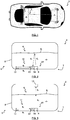
- the invention relates to a tank 1 intended to be mounted in a motor vehicle 3.
- the tank 1 can thus be a fuel tank for a heat engine 2, an additive tank for fuel. of a heat engine 2, a tank of product for the depollution of the exhaust gases of a heat engine 2, a water tank for the intake (air or air - fuel mixture) of a heat engine 2 or a fuel tank for a fuel cell.
- the fluid 4 can be fuel such as gasoline or diesel, cerine, urea, ammonia, demineralized water or dihydrogen.
- the fluid reservoir 1 4 comprises a body 5 arranged to receive the fluid 4.
- the reservoir 1 comprises a system 7 for extracting the fluid 4 from the reservoir 1 for use in the motor vehicle 3.
- the system 7 of extraction may in particular include a pumping device provided with a pump 8 actuated by a motor and a control valve.
- the reservoir 1 further comprises a system 9 for measuring a parameter of the fluid 4 in the reservoir 1 in order to manage the use of the fluid 4 in the motor vehicle 3.
- the system 9 of measurement is arranged to capture acoustic waves 6 generated by another system whose main function is not to emit an acoustic wave 6 in order to determine, for example, the level and / or the concentration and / or the density and / or the pollution (degree of purity) and / or the conductivity of the fluid 4 in the tank 1.
- the other system used will be the system 7 of extraction in the fluid 4 .
- the measurement system 9 makes it possible to capture the movements of molecules in the fluid 4, the variations in speed of molecules in the fluid 4, the variations in density in the fluid 4 or the variations in pressure in the fluid 4 induced by the acoustic waves 6 generated by the extraction system 7.
- the acoustic waves 6 could thus be generated by the operation of the pump 8, its motor, the valve or any other element of the extraction system 7. It is therefore understood that the measuring system 9 can be used when the extraction system 7 is in operation or by controlling the operation of the extraction system 7 at a chosen time.
- the first embodiment uses the pump 8 as an acoustic wave generator 6.
- the measuring system 9 comprises a device 11 for detecting the concentration of the fluid 4.
- the device 11 preferably comprises a reflection element 12 mounted at a distance fixed with respect to the extraction system 7 in order to know in advance the distance which will be traveled by the acoustic waves 6 generated by the extraction system 7 in the fluid 4.
- the element 12 can thus be formed as a mounted plate projecting inside the reservoir 1.
- the reflection element 12 may alternatively be formed by a part of the body 5 of the reservoir 1.
- the device 11 comprises at least one acoustic sensor 13 mounted between the reflection element 12 and the extraction system 7 in order to capture the acoustic waves. 6 th emitted by the extraction system 7 as well as their echo, that is to say the acoustic waves 6 r reflected by the reflection element 12.
- the acoustic sensors 13 are preferably wide or narrow frequency band ultrasonic receivers.
- the device 11 comprises a calculation module 14 arranged to determine the concentration of the fluid 4. More precisely, the calculation module 14 determines, from the fixed distance, the type of fluid and the time elapsed between the detections of each. 6 th acoustic wave emitted by the extraction system 7 and its 6 r echo returned by the reflection element 12, the concentration of the fluid 4. Indeed, the variation in time to perform the fixed distance makes it possible to monitor the variations concentration of the fluid 4.
- a prior calibration according to the arrangement of the reservoir 1, the fixed distance and the type of fluid 4 allows the calculation module 14 to precisely measure the effective concentration and to adapt to possible manufacturing variations for the same type of tank 1.
- a correspondence table could, for example, be previously stored in the memory of the sensor 13 which determines the value of the concentration of the fluid 4 by interpolation or comparison.
- the concentration is proportional to the duration between the emission and the reception of the acoustic wave 6, over a fixed distance, propagated in the medium
- 9 measuring system also comprises, according to the first embodiment, a device 15 for detecting the fluid level 4 having at least a 13 acoustic sensor mounted in the reservoir 1 to receive the acoustic waves 6th issued by the system 7 extraction as well as their echo, that is to say the acoustic waves 6 r reflected by the upper surface 4 s of the fluid 4.
- the upper part of the tank 1 mainly comprising a filling gas such as air or a mixture between a filling gas and another phase of the fluid 4, the 6 th acoustic wave emitted will be mainly reflected 6 r and thus return to the sensor 13.
- the device 15 comprises a calculation module 14 arranged to determine the level of the fluid 4, that is to say the height of the upper surface 4 s of the fluid 4 in the reservoir 1. More precisely, the module 14 calculation determines, from the type of fluid and the time elapsed between the detections of each 6 th acoustic wave generated by the extraction system 7 and its echo 6 r returned by the upper surface 4 s of the fluid 4, the distance traveled and therefore the level of the fluid 4 in the reservoir 1. In fact, the variation in time to perform the outward and return movement makes it possible to monitor the variations in the level of the fluid 4.
- a prior calibration as a function of the arrangement of the reservoir 1, of the concentration of the fluid 4 and of the type of fluid 4 allows the calculation module 14 to precisely measure the effective level and to adapt to any manufacturing variations for the same type of reservoir 1.
- the level of fluid 4 is equal to the product of the speed of sound in the medium and the time between the emission and the reception of wave 6 acoustic. Since the speed of sound in a medium is sensitive to the density of the medium and therefore to the concentration, concentration compensation is useful to guarantee detection performance.
- the devices 11, 15 for detecting the concentration and the level of the fluid 4 of the system 9 can be linked in their operation, or even share one and the same sensor 13. It is then immediately realized that the invention allows, without reduce the quality of measurements, use fewer elements to carry out detections in order to consume less energy and weigh less.
- the fluid reservoir 1 4 comprises a body 5 arranged to receive the fluid 4.
- the reservoir 1 further comprises a system 7 for extracting the fluid 4 from the reservoir 1 for its use in the motor vehicle 3 identical to that of the first embodiment.
- the reservoir 1 further comprises a system 9 for measuring a parameter of the fluid 4 in the reservoir 1 in order to manage the use of the fluid 4 in the motor vehicle 3.
- the system 9 of measurement is arranged to capture acoustic waves 6 generated by another system whose main function is not to emit an acoustic wave 6 in order to determine, for example, the level and / or the concentration of the fluid 4 in the tank 1
- the other system used will be the system 7 for extraction in the fluid 4.
- the measurement system 9 makes it possible to capture the movements of molecules in the fluid 4, the variations in speed of molecules in the fluid 4, the variations in density in the fluid 4 or the variations in pressure in the fluid 4 induced by the acoustic waves 6 generated by the extraction system 7.
- the acoustic waves 6 could thus be generated by the operation of the pump 8, its motor, the valve or any other element of the extraction system 7. It is therefore understood that the measuring system 9 can be used when the extraction system 7 is in operation or by controlling the operation of the extraction system 7 at a chosen time.
- the second embodiment uses the pump 8 as an acoustic wave generator 6.
- the measuring system 9 comprises a device 11 for detecting the concentration of the fluid 4 identical to that of the first embodiment with the same effects and advantages in order to precisely measure the effective concentration of the fluid 4 in the reservoir 1.
- the measuring system 9 also comprises, according to the second embodiment, a device 15 for detecting the level of the fluid 4 comprising at least two acoustic sensors 13 mounted in the tank 1 in order to pick up the acoustic waves 6 th emitted by the system 7 extraction as well as the acoustic waves 6 t transmitted through the upper surface 4 s of the fluid 4.
- the upper part of the tank 1 mainly comprising a filling gas such as air or a mixture between a filling gas and another phase of the fluid 4, the 6 th acoustic wave emitted will be partially transmitted 6 t and thus arrive towards the second sensor 13.
- the device 15 comprises a calculation module 14 arranged to determine the level of the fluid 4, that is to say the height of the upper surface 4 s of the fluid 4 in the reservoir 1. More precisely, the module 14 calculation determines, from the distance between the first and second acoustic sensors 13, the type of fluid, the type of filling gas and the time elapsed between the detection of the first acoustic sensor 13 and the second acoustic sensor 13 for each wave acoustics generated by the extraction system 7, the level of the fluid 4 in the reservoir and therefore the level of the fluid 4 in the reservoir 1. In fact, the variation in duration between the detections of the first and second acoustic sensors 13 makes it possible to monitor variations in the level of the fluid 4. Of course, a preliminary calibration according to the arrangement of the reservoir 1, the concentration of the fluid 4, the type of filling gas and the type of fluid 4 allows the module 14 to calculate pre precisely measure the effective level and adapt to any manufacturing variations for the same type of tank 1.
- the devices 11, 15 for detecting the concentration and the level of the fluid 4 of the system 9 can be linked in their operation, or even share one of the sensors 13. It is then immediately realized that the invention allows, without reducing the quality of measurements, to use fewer elements to make the detections in order to consume less energy and weigh less.
- the fluid reservoir 1 4 comprises a body 5 arranged to receive the fluid 4.
- the reservoir 1 comprises a system 7 for extracting the fluid 4 from the reservoir 1 for its use in the motor vehicle 3 identical to that in the first and second embodiments.
- the reservoir 1 comprises a system 9 for measuring several parameters of the fluid 4 in the reservoir 1 in order to manage the use of the fluid 4 in the motor vehicle 3.
- the measuring system 9 is arranged for picking up acoustic waves 6 generated by another system whose main function is not to emit an acoustic wave 6 in order to determine, for example, the level and / or concentrations of the fluid 4 in the tank 1.
- the other system used will be the system 7 for extraction in the fluid 4.
- the measurement system 9 makes it possible to capture the movements of molecules in the fluid 4, the variations in speed of molecules in the fluid 4, the variations in density in the fluid 4 or the variations in pressure in the fluid 4 induced by the acoustic waves 6 generated by the extraction system 7.
- the acoustic waves 6 could thus be generated by the operation of the pump 8, its motor, the valve or any other element of the extraction system 7. It is therefore understood that the measuring system 9 can be used when the extraction system 7 is in operation or by controlling the operation of the extraction system 7 at a chosen time.
- the third embodiment uses the pump 8 as a generator of acoustic waves 6.
- the measurement system 9 comprises several acoustic sensors 13 1 , 13 2 , 13 3 , 13 n mounted in the tank 1 in order to capture at several places the acoustic waves emitted 6 th by the extraction system 7 but also reflected 6 r by the upper surface 4 s of the fluid 4 or transmitted 6 t through the upper surface 4 s of the fluid 4.
- the acoustic sensors 13 1 , 13 2 , 13 3 , 13 n are preferably mounted at a distance and an orientation determined between them in order to allow the determination of the level of the fluid 4 in the reservoir 1 but also the determination of the concentration of the fluid 4 in several different places.
- the tanks 1 of the motor vehicle 3 are subjected to the climatic hazards of the environments crossed. Thus, depending on the nature of the fluid 4, freezing and thawing phases may occur. It is then understood that the phase of the fluid 4 and, incidentally, the propagation of the acoustic waves 6 can be modified.
- the acoustic sensors 13 1 , 13 2 , 13 3 , 13 n are therefore preferably mounted at a distance and an orientation determined between them.
- the distribution of the acoustic sensors 13 1 , 13 2 , 13 3 , 13 n could be carried out in a circular, spherical, polygonal, prismatic or rectilinear manner.
- the acoustic sensors 13 1 , 13 2 , 13 3 , 13 n are aligned at a constant distance between them between the bottom of the tank 1 and the upper part of the tank 1.
- Each sensor 13 1 , 13 2 , 13 3 , 13 n acoustics therefore detects the acoustic waves 6 generated by the extraction system 7.
- the measuring system 9 also comprises a calculation module 14 arranged to determine the level and / or concentrations of the fluid 4. More precisely, the calculation module 14 determines, from the distance and the orientation between the sensors 13 1. , 13 2 , 13 3 , 13 n acoustic, the type of fluid 4 and the time elapsed between the detections of the acoustic sensors 13 1 , 13 2 , 13 3 , 13 n for each acoustic wave generated by the extraction system 7, the level and concentrations of fluid 4 in tank 1.
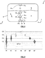
- the figure 5 shows an example of signals obtained advantageously by the measuring system 9 according to the invention.
- the abscissa designates the elapsed time and the ordinate shows the signals of each sensor 13 1 , 13 2 , 13 3 , 13 n .
- the sensor 13 1 detects a wave 6 and 1 emitted by the extraction system 7 with very great intensity.
- the sensor 13 2 detects the same wave 6 and 2 emitted by the extraction system 7 with great intensity.
- the sensor 13 3 detects the same wave 6 and 3 emitted by the extraction system 7 with an average intensity.
- the sensor 13 n detects the same wave 6 ttn transmitted through the upper surface 4 s of the fluid 4 with a lower intensity.
- the sensor 13 3 detects the same wave reflected by the upper surface 4 s of the fluid 4.
- the sensor 13 2 detects the same wave reflected by the upper surface 4 s of the fluid 4.
- the sensor 13 1 detects the same wave reflected by the upper surface 4 s of the fluid 4.
- an average level value of the fluid 4 in the tank 1 can be obtained by the calculation module 14 by the duration t1'-t1 and the position of the sensor 13 1 in the tank 1. Indeed, the variation the duration t1'-t1 to perform the outward and return movement allows monitoring of fluid level variations 4.
- a more precise value of the level of the fluid 4 can be obtained using sequentially the concentration of the fluid 4 and the time between each sensor 13 1 , 13 2 , 13 3 , 13 n by the calculation module 14.
- a preliminary calibration according to the arrangement of the reservoir 1, the distribution of the acoustic sensors 13 1 , 13 2 , 13 3 , 13 n , the concentration of the fluid 4 and the type of fluid 4 allows the module 14 calculation to precisely measure the effective level and / or the effective concentrations and to adapt to any manufacturing variations for the same type of tank 1
- the invention is not limited to the embodiments and variants presented and other embodiments and variants will be apparent to those skilled in the art. It is in particular possible that the acoustic waves are generated by a system other than the extraction system 7. This other system could thus be present or not in the tank 1 such as, for example, the engine 2 of the motor vehicle 3 or the ambient noise around the tank 1.
- the measuring device 9 could be applied to acoustic waves 6 emitted not by another system whose main function is not to emit a wave 6. acoustic but by the measuring device 9 itself, that is to say a dedicated sound transmitter belonging to the measuring device 9.
- the measuring system 9 cannot be limited to the level detection and / or the detection of the concentration of the fluid 4 as explained above.
- the measuring system 9 can be arranged to pick up acoustic waves 6 generated by another system, the main function of which is not emit an acoustic wave 6 in order to determine, for example, the density and / or the pollution (degree of purity) and / or the conductivity of the coolant 4 in the tank 1.
- This information is in fact useful for controlling the reduction the temperature of the air intake or the air-fuel mixture of heat engines, for example.
Landscapes
- Physics & Mathematics (AREA)
- Engineering & Computer Science (AREA)
- General Physics & Mathematics (AREA)
- Life Sciences & Earth Sciences (AREA)
- Chemical & Material Sciences (AREA)
- Acoustics & Sound (AREA)
- Mechanical Engineering (AREA)
- Sustainable Development (AREA)
- Sustainable Energy (AREA)
- Combustion & Propulsion (AREA)
- Transportation (AREA)
- Remote Sensing (AREA)
- Radar, Positioning & Navigation (AREA)
- Analytical Chemistry (AREA)
- Health & Medical Sciences (AREA)
- Biochemistry (AREA)
- General Health & Medical Sciences (AREA)
- Immunology (AREA)
- Pathology (AREA)
- Electromagnetism (AREA)
- Thermal Sciences (AREA)
- Fluid Mechanics (AREA)
- Computer Networks & Wireless Communication (AREA)
- Investigating Or Analyzing Materials By The Use Of Ultrasonic Waves (AREA)
- Measurement Of Levels Of Liquids Or Fluent Solid Materials (AREA)
Claims (14)
- Tank (1) für Fluid (4) für Kraftfahrzeug (3), aufweisend einen Körper (5), der zum Aufnehmen des Fluids (4) eingerichtet ist, und ein System (9) zum Messen eines Parameters des Fluids (4) in dem Tank (1) ausgehend von einer akustischen Welle, wobei das Messsystem (9) wenigstens einen akustischen Sensor (13) aufweist, der dazu bestimmt ist, eine akustische Welle (6) zu empfangen, dadurch gekennzeichnet, dass die akustische Welle (6), Schall genannt, von einem anderen System (7) erzeugt wird, dessen Hauptfunktion nicht das Aussenden einer akustischen Welle ist.
- Tank (1) nach dem vorhergehenden Anspruch, wobei das andere System ein System (7) zum Abziehen des Fluids (4) aus dem Tank (1) ist.
- Tank (1) nach Anspruch 1 oder 2, wobei das Messsystem (9) eine Vorrichtung (11) für die Detektion der Konzentration des Fluids (4) aufweist, die ein akustisches Reflexionselement, das in einem festen Abstand zu dem anderen System montiert ist, den akustischen Sensor (13), der zwischen dem Reflexionselement und dem anderen System (7) montiert ist, um die akustischen Wellen (6), die von dem anderen System (7) erzeugt werden, zu empfangen, und ein Rechenmodul (14), das eingerichtet ist, um die Konzentration des Fluids (4) zu bestimmen, aufweist.
- Tank (1) nach dem vorhergehenden Anspruch, wobei das akustische Reflexionselement von dem Körper (5) des Tanks (1) oder einer Platte (12), die in dem Tank (1) montiert ist, gebildet ist.
- Tank (1) nach Anspruch 3 oder 4, wobei das Rechenmodul (14) Mittel aufweist, um, ausgehend von dem festen Abstand, vom Typ des Fluids (4) und von der Zeit, die zwischen den Detektionen jeder akustischen Welle (6), die von dem anderen System (7) erzeugt wird, und ihres von dem Reflexionselement zurückgegebenen Echos vergangen ist, die Konzentration des Fluids (4) zu bestimmen.
- Tank (1) nach einem der vorhergehenden Ansprüche, wobei das Messsystem (9) eine Vorrichtung (11) für die Detektion des Pegels des Fluids (4) aufweist, die den akustischen Sensor (13), der in dem Tank (1) montiert ist, um die akustischen Wellen (6), die von dem anderen System erzeugt werden, zu empfangen, und ein Rechenmodul (14), das eingerichtet ist, um die Konzentration des Fluids (4) zu bestimmen, aufweist.
- Tank (1) nach dem vorhergehenden Anspruch, wobei das Rechenmodul (14) Mittel aufweist, um, ausgehend vom Typ des Fluids und von der Zeit, die zwischen den Detektionen jeder akustischen Welle (6), die von dem anderen System (7) erzeugt wird, und ihres von der Oberfläche (4s) des Fluids (4) reflektierten Echos vergangen ist, den Pegel des Fluids (4) in dem Tank (1) zu bestimmen.
- Tank (1) nach Anspruch 6, wobei das Messsystem (9) einen ersten akustischen Sensor (13) aufweist, der auf dem Boden des Tanks (1) montiert ist, einen zweiten akustischen Sensor (13) aufweist, der auf der Oberseite des Tanks (1) montiert ist, wobei das Rechenmodul (14) Mittel aufweist, um, ausgehend von dem Abstand zwischen dem ersten und zweiten akustischen Sensor (13), vom Typ des Fluids (4), vom Typ des Füllgases und von der Zeit, die zwischen der Detektion des ersten akustischen Sensors (13) und des zweiten akustischen Sensors (13) für jede akustische Welle (6), die von dem anderen System (7) erzeugt wird, vergangen ist, den Pegel des Fluids (4) in dem Tank (1) zu bestimmen.
- Tank (1) nach einem der Ansprüche 1 oder 2, wobei das Messsystem (9) mehrere akustische Sensoren (13), die in dem Tank (1) montiert sind, um an mehreren Stellen die akustischen Wellen (6) zu empfangen, die von dem anderen System (7) erzeugt werden, und ein Rechenmodul (14), das eingerichtet ist, um den Pegel und/oder Konzentrationen des Fluids (4) zu bestimmen, aufweist.
- Tank (1) nach dem vorhergehenden Anspruch, wobei die akustischen Sensoren (13) in einem bestimmten Abstand und einer bestimmten Ausrichtung zueinander montiert sind, wobei das Rechenmodul (14) Mittel aufweist, um, ausgehend von dem Abstand und von der Ausrichtung zwischen den akustischen Sensoren (13), vom Typ des Fluids (4) und von der Zeit, die zwischen den Detektionen der akustischen Sensoren (13) für jede akustische Welle (6), die von dem anderen System (7) erzeugt wird, vergangen ist, den Pegel und/oder die Konzentrationen des Fluids (4) in dem Tank (1) zu bestimmen.
- Tank (1) nach dem vorhergehenden Anspruch, wobei die akustischen Sensoren (13) in einem konstanten Abstand zueinander in Flucht sind.
- Kraftfahrzeug (3), dadurch gekennzeichnet, dass es einen Tank (1) nach einem der vorhergehenden Ansprüche aufweist.
- Kraftfahrzeug (3), nach dem vorhergehenden Anspruch, wobei der Tank (1) ein Tank für Kraftstoff für einen Verbrennungsmotor (2), ein Tank für Additiv für den Kraftstoff eines Verbrennungsmotors (2), ein Tank für ein Produkt für die Abgasreinigung eines Verbrennungsmotors (2) oder ein Tank für Brennstoff für eine Brennstoffzelle ist.
- Verfahren zum Messen eines Parameters eines Fluids (4), das in einem Tank (1) für Kraftfahrzeug (3) enthalten ist, dadurch gekennzeichnet, dass es die folgenden Schritte aufweist:- Empfangen einer akustischen Welle (6), Schall genannt, die sich in dem Fluid (4) ausbreitet und von einem System (7) erzeugt wird, dessen Hauptfunktion nicht das Aussenden einer akustischen Welle ist;- Bestimmen des Parameters des Fluids (4) ausgehend von einem Wert, der ausgehend von der empfangenen Welle gemessen wird.
Applications Claiming Priority (2)
| Application Number | Priority Date | Filing Date | Title |
|---|---|---|---|
| FR1757319A FR3069495B1 (fr) | 2017-07-31 | 2017-07-31 | Systeme de mesure d'un parametre d'un fluide dans un reservoir. |
| PCT/EP2018/070374 WO2019025300A1 (fr) | 2017-07-31 | 2018-07-27 | Systeme de mesure d'un parametre d'un fluide dans un reservoir |
Publications (2)
| Publication Number | Publication Date |
|---|---|
| EP3661792A1 EP3661792A1 (de) | 2020-06-10 |
| EP3661792B1 true EP3661792B1 (de) | 2021-05-05 |
Family
ID=59746228
Family Applications (1)
| Application Number | Title | Priority Date | Filing Date |
|---|---|---|---|
| EP18746923.4A Active EP3661792B1 (de) | 2017-07-31 | 2018-07-27 | System zur messung eines parameters eines fluids in einem tank |
Country Status (5)
| Country | Link |
|---|---|
| US (1) | US10775348B2 (de) |
| EP (1) | EP3661792B1 (de) |
| CN (1) | CN110944864B (de) |
| FR (1) | FR3069495B1 (de) |
| WO (1) | WO2019025300A1 (de) |
Families Citing this family (8)
| Publication number | Priority date | Publication date | Assignee | Title |
|---|---|---|---|---|
| US11231311B2 (en) | 2019-05-31 | 2022-01-25 | Perceptive Sensor Technologies Llc | Non-linear ultrasound method and apparatus for quantitative detection of materials |
| FR3107764B1 (fr) | 2020-02-28 | 2022-05-06 | Plastic Omnium Advanced Innovation & Res | Système de mesure d’un paramètre d’un fluide |
| CN116940810A (zh) | 2020-12-04 | 2023-10-24 | 感知传感器技术股份有限公司 | 多次反射声音信号材料检测 |
| US11946905B2 (en) * | 2020-12-30 | 2024-04-02 | Perceptive Sensor Technologies, Inc. | Evaluation of fluid quality with signals |
| CN113406210A (zh) * | 2021-07-23 | 2021-09-17 | 上海季丰电子股份有限公司 | 一种超声波扫查仪高质量成像装置及其工作方法 |
| ZA202202826B (en) * | 2022-01-14 | 2022-12-21 | African New Energies Ltd | Fano based crab sensor and system for fuel quality, level, and volume monitoring for irregular shaped fuel tanks |
| US11860014B2 (en) | 2022-02-11 | 2024-01-02 | Perceptive Sensor Technologies, Inc. | Acoustic signal detection of material composition in static and dynamic conditions |
| WO2024091308A1 (en) | 2022-07-19 | 2024-05-02 | Perceptive Sensor Technologies, Inc. | Acoustic signal material identification with nanotube couplant |
Family Cites Families (13)
| Publication number | Priority date | Publication date | Assignee | Title |
|---|---|---|---|---|
| JPH0777477A (ja) * | 1992-09-02 | 1995-03-20 | Rion Co Ltd | リーク検出装置及び方法 |
| US5522428A (en) * | 1994-08-29 | 1996-06-04 | Duvall; Paul F. | Natural gas vehicle tank life sensor and control |
| DE10354473B4 (de) * | 2003-11-21 | 2006-05-24 | Fraunhofer-Gesellschaft zur Förderung der angewandten Forschung e.V. | Mehrkanalige Ultraschall-Messeinrichtung |
| JP5371298B2 (ja) * | 2008-07-04 | 2013-12-18 | 本田技研工業株式会社 | 圧力タンク及び圧力タンクにおける内部欠陥検出方法 |
| EP2333514A1 (de) * | 2009-11-30 | 2011-06-15 | Berlin Heart GmbH | Einrichtung und Verfahren zur Messung von strömungsmechanisch wirksamen Materialparametern eines Fluids |
| US8902078B2 (en) * | 2010-12-08 | 2014-12-02 | Halliburton Energy Services, Inc. | Systems and methods for well monitoring |
| FR2978551B1 (fr) * | 2011-07-25 | 2014-04-11 | Inst Soudure | Controle de reservoir par emission acoustique |
| DE102012217891A1 (de) * | 2012-10-01 | 2014-04-03 | Robert Bosch Gmbh | Verfahren zur Füllstandsbestimmung eines Tanks |
| KR20160024190A (ko) * | 2014-08-25 | 2016-03-04 | 주식회사 코아비스 | 연료 유량검출장치 |
| FR3035965B1 (fr) * | 2015-05-04 | 2017-05-12 | Peugeot Citroen Automobiles Sa | Dispositif de detection d’un point de fuite sur un reservoir |
| CN107923781B (zh) * | 2015-06-22 | 2020-09-29 | 沙特阿拉伯石油公司 | 提供基于熵的多相流表征的系统、方法和计算机介质 |
| US10161909B2 (en) * | 2015-10-29 | 2018-12-25 | Mustang Sampling Llc | Steady state fluid flow verification for sample takeoff |
| CN205991825U (zh) * | 2016-08-31 | 2017-03-01 | 青岛澳波泰克安全设备有限责任公司 | 一种用于储油油罐液位监测的无线传输报警装置 |
-
2017
- 2017-07-31 FR FR1757319A patent/FR3069495B1/fr not_active Expired - Fee Related
-
2018
- 2018-07-27 EP EP18746923.4A patent/EP3661792B1/de active Active
- 2018-07-27 CN CN201880048256.6A patent/CN110944864B/zh not_active Expired - Fee Related
- 2018-07-27 US US16/634,718 patent/US10775348B2/en not_active Expired - Fee Related
- 2018-07-27 WO PCT/EP2018/070374 patent/WO2019025300A1/fr not_active Ceased
Also Published As
| Publication number | Publication date |
|---|---|
| WO2019025300A1 (fr) | 2019-02-07 |
| US10775348B2 (en) | 2020-09-15 |
| FR3069495A1 (fr) | 2019-02-01 |
| FR3069495B1 (fr) | 2019-08-02 |
| EP3661792A1 (de) | 2020-06-10 |
| CN110944864A (zh) | 2020-03-31 |
| US20200200711A1 (en) | 2020-06-25 |
| CN110944864B (zh) | 2021-02-09 |
Similar Documents
| Publication | Publication Date | Title |
|---|---|---|
| EP3661792B1 (de) | System zur messung eines parameters eines fluids in einem tank | |
| EP0691527B1 (de) | Vorrichtung und Verfahren zum Messen des Geschwindigkeitsprofiles in einem Mehrphasenfluid | |
| FR2922598A1 (fr) | Procede pour determiner l'inflammabilite du carburant de qualite inconnue. | |
| EP2729677B1 (de) | Vorrichtung zur messung der harnstoffkonzentration | |
| EP3803092B1 (de) | Einspritzsystem einer wässerigen lösung in einem verbrennungsmotor | |
| FR2712350A1 (fr) | Procédé et dispositif d'optimisation ou remplissage en air d'un cylindre de moteur à combustion interne. | |
| WO2012150002A1 (fr) | Dispositif de mesure de caracteristiques dans un reservoir d'uree | |
| EP1890024A1 (de) | Bestimmung des Verbrennungsbeginns in einem Verbrennungsmotor | |
| EP3548851B1 (de) | Verfahren zur schätzung eines aufgetauten, in flüssiger form in einem tank vorhandenen volumens | |
| FR3094417A1 (fr) | Determination d’une derive du debit statique de carburant d’un injecteur piezo-electrique d’un moteur thermique de vehicule automobile | |
| FR2565345A1 (fr) | Dispositif de mesure par ultrasons du niveau et/ou du volume d'un liquide dans un recipient | |
| WO2009019345A1 (fr) | Procede et dispositif pour diagnostiquer une fuite d'injecteur dans un moteur a combustion interne | |
| FR3107764A1 (fr) | Système de mesure d’un paramètre d’un fluide | |
| FR3074573A1 (fr) | Procede de mesure par ultrasons | |
| EP2507491B1 (de) | System und verfahren zur schätzung der masse von in einem partikelfilter aufbewahrten partikeln eines kraftfahrzeugs | |
| EP1475528B1 (de) | Einrichtung und Methode zur Steuerung der Kraftstoffeinspritzung für einen Verbrennungsmotor | |
| EP3940379A1 (de) | Vorrichtung zur erkennung des einfrierens eines wassertanks an bord eines fahrzeugs | |
| FR2713777A1 (fr) | Dispositif de mesure de la composition d'un liquide, en particulier de la mesure du taux d'additif dans un carburant de véhicule automobile. | |
| FR2945078A1 (fr) | Procede de controle du fonctionnement d'un moteur | |
| EP2836809B1 (de) | Verfahren zur erkennung eines druckverlustes in einem zylinder eines hybriden pneumatisch-thermischen antriebssystems | |
| FR2994214A1 (fr) | Moteur a combustion equipe d'un dispositif de detection du cliquetis comportant un capteur de vibrations monte sur la rampe d'injection du moteur | |
| FR2935112A3 (fr) | Systeme et procede d'estimation de la quantite de carburant contenu dans un reservoir de vehicule automobile | |
| FR3116343A1 (fr) | Procédé de gestion d’un dispositif déterminant la qualité d’un liquide et dispositif pour la mise en œuvre du procédé | |
| FR2830573A1 (fr) | Dispositif d'alimentation en carburant pour moteur a combustion interne | |
| WO2009007609A2 (fr) | Procede et dispositif de commande d'injections d'un moteur, vehicule automobile muni du dispositif |
Legal Events
| Date | Code | Title | Description |
|---|---|---|---|
| STAA | Information on the status of an ep patent application or granted ep patent |
Free format text: STATUS: UNKNOWN |
|
| STAA | Information on the status of an ep patent application or granted ep patent |
Free format text: STATUS: THE INTERNATIONAL PUBLICATION HAS BEEN MADE |
|
| PUAI | Public reference made under article 153(3) epc to a published international application that has entered the european phase |
Free format text: ORIGINAL CODE: 0009012 |
|
| STAA | Information on the status of an ep patent application or granted ep patent |
Free format text: STATUS: REQUEST FOR EXAMINATION WAS MADE |
|
| 17P | Request for examination filed |
Effective date: 20200205 |
|
| AK | Designated contracting states |
Kind code of ref document: A1 Designated state(s): AL AT BE BG CH CY CZ DE DK EE ES FI FR GB GR HR HU IE IS IT LI LT LU LV MC MK MT NL NO PL PT RO RS SE SI SK SM TR |
|
| AX | Request for extension of the european patent |
Extension state: BA ME |
|
| RIN1 | Information on inventor provided before grant (corrected) |
Inventor name: FERHAN, MEHDI Inventor name: SANOGO, YACOUBA Inventor name: FRANCINI, FRANCOIS |
|
| DAV | Request for validation of the european patent (deleted) | ||
| DAX | Request for extension of the european patent (deleted) | ||
| GRAP | Despatch of communication of intention to grant a patent |
Free format text: ORIGINAL CODE: EPIDOSNIGR1 |
|
| STAA | Information on the status of an ep patent application or granted ep patent |
Free format text: STATUS: GRANT OF PATENT IS INTENDED |
|
| INTG | Intention to grant announced |
Effective date: 20210210 |
|
| RIN1 | Information on inventor provided before grant (corrected) |
Inventor name: FRANCINI, FRANCOIS Inventor name: FERHAN, MEHDI Inventor name: SANOGO, YACOUBA |
|
| GRAS | Grant fee paid |
Free format text: ORIGINAL CODE: EPIDOSNIGR3 |
|
| GRAA | (expected) grant |
Free format text: ORIGINAL CODE: 0009210 |
|
| STAA | Information on the status of an ep patent application or granted ep patent |
Free format text: STATUS: THE PATENT HAS BEEN GRANTED |
|
| AK | Designated contracting states |
Kind code of ref document: B1 Designated state(s): AL AT BE BG CH CY CZ DE DK EE ES FI FR GB GR HR HU IE IS IT LI LT LU LV MC MK MT NL NO PL PT RO RS SE SI SK SM TR |
|
| REG | Reference to a national code |
Ref country code: GB Ref legal event code: FG4D Free format text: NOT ENGLISH |
|
| REG | Reference to a national code |
Ref country code: CH Ref legal event code: EP |
|
| REG | Reference to a national code |
Ref country code: AT Ref legal event code: REF Ref document number: 1389396 Country of ref document: AT Kind code of ref document: T Effective date: 20210515 |
|
| REG | Reference to a national code |
Ref country code: IE Ref legal event code: FG4D Free format text: LANGUAGE OF EP DOCUMENT: FRENCH |
|
| REG | Reference to a national code |
Ref country code: DE Ref legal event code: R096 Ref document number: 602018016778 Country of ref document: DE |
|
| REG | Reference to a national code |
Ref country code: LT Ref legal event code: MG9D |
|
| REG | Reference to a national code |
Ref country code: AT Ref legal event code: MK05 Ref document number: 1389396 Country of ref document: AT Kind code of ref document: T Effective date: 20210505 |
|
| PG25 | Lapsed in a contracting state [announced via postgrant information from national office to epo] |
Ref country code: HR Free format text: LAPSE BECAUSE OF FAILURE TO SUBMIT A TRANSLATION OF THE DESCRIPTION OR TO PAY THE FEE WITHIN THE PRESCRIBED TIME-LIMIT Effective date: 20210505 Ref country code: LT Free format text: LAPSE BECAUSE OF FAILURE TO SUBMIT A TRANSLATION OF THE DESCRIPTION OR TO PAY THE FEE WITHIN THE PRESCRIBED TIME-LIMIT Effective date: 20210505 Ref country code: FI Free format text: LAPSE BECAUSE OF FAILURE TO SUBMIT A TRANSLATION OF THE DESCRIPTION OR TO PAY THE FEE WITHIN THE PRESCRIBED TIME-LIMIT Effective date: 20210505 Ref country code: BG Free format text: LAPSE BECAUSE OF FAILURE TO SUBMIT A TRANSLATION OF THE DESCRIPTION OR TO PAY THE FEE WITHIN THE PRESCRIBED TIME-LIMIT Effective date: 20210805 Ref country code: AT Free format text: LAPSE BECAUSE OF FAILURE TO SUBMIT A TRANSLATION OF THE DESCRIPTION OR TO PAY THE FEE WITHIN THE PRESCRIBED TIME-LIMIT Effective date: 20210505 |
|
| PG25 | Lapsed in a contracting state [announced via postgrant information from national office to epo] |
Ref country code: PT Free format text: LAPSE BECAUSE OF FAILURE TO SUBMIT A TRANSLATION OF THE DESCRIPTION OR TO PAY THE FEE WITHIN THE PRESCRIBED TIME-LIMIT Effective date: 20210906 Ref country code: SE Free format text: LAPSE BECAUSE OF FAILURE TO SUBMIT A TRANSLATION OF THE DESCRIPTION OR TO PAY THE FEE WITHIN THE PRESCRIBED TIME-LIMIT Effective date: 20210505 Ref country code: RS Free format text: LAPSE BECAUSE OF FAILURE TO SUBMIT A TRANSLATION OF THE DESCRIPTION OR TO PAY THE FEE WITHIN THE PRESCRIBED TIME-LIMIT Effective date: 20210505 Ref country code: PL Free format text: LAPSE BECAUSE OF FAILURE TO SUBMIT A TRANSLATION OF THE DESCRIPTION OR TO PAY THE FEE WITHIN THE PRESCRIBED TIME-LIMIT Effective date: 20210505 Ref country code: LV Free format text: LAPSE BECAUSE OF FAILURE TO SUBMIT A TRANSLATION OF THE DESCRIPTION OR TO PAY THE FEE WITHIN THE PRESCRIBED TIME-LIMIT Effective date: 20210505 Ref country code: NO Free format text: LAPSE BECAUSE OF FAILURE TO SUBMIT A TRANSLATION OF THE DESCRIPTION OR TO PAY THE FEE WITHIN THE PRESCRIBED TIME-LIMIT Effective date: 20210805 Ref country code: GR Free format text: LAPSE BECAUSE OF FAILURE TO SUBMIT A TRANSLATION OF THE DESCRIPTION OR TO PAY THE FEE WITHIN THE PRESCRIBED TIME-LIMIT Effective date: 20210806 Ref country code: IS Free format text: LAPSE BECAUSE OF FAILURE TO SUBMIT A TRANSLATION OF THE DESCRIPTION OR TO PAY THE FEE WITHIN THE PRESCRIBED TIME-LIMIT Effective date: 20210905 |
|
| REG | Reference to a national code |
Ref country code: NL Ref legal event code: MP Effective date: 20210505 |
|
| PG25 | Lapsed in a contracting state [announced via postgrant information from national office to epo] |
Ref country code: NL Free format text: LAPSE BECAUSE OF FAILURE TO SUBMIT A TRANSLATION OF THE DESCRIPTION OR TO PAY THE FEE WITHIN THE PRESCRIBED TIME-LIMIT Effective date: 20210505 |
|
| PG25 | Lapsed in a contracting state [announced via postgrant information from national office to epo] |
Ref country code: CZ Free format text: LAPSE BECAUSE OF FAILURE TO SUBMIT A TRANSLATION OF THE DESCRIPTION OR TO PAY THE FEE WITHIN THE PRESCRIBED TIME-LIMIT Effective date: 20210505 Ref country code: DK Free format text: LAPSE BECAUSE OF FAILURE TO SUBMIT A TRANSLATION OF THE DESCRIPTION OR TO PAY THE FEE WITHIN THE PRESCRIBED TIME-LIMIT Effective date: 20210505 Ref country code: SM Free format text: LAPSE BECAUSE OF FAILURE TO SUBMIT A TRANSLATION OF THE DESCRIPTION OR TO PAY THE FEE WITHIN THE PRESCRIBED TIME-LIMIT Effective date: 20210505 Ref country code: RO Free format text: LAPSE BECAUSE OF FAILURE TO SUBMIT A TRANSLATION OF THE DESCRIPTION OR TO PAY THE FEE WITHIN THE PRESCRIBED TIME-LIMIT Effective date: 20210505 Ref country code: SK Free format text: LAPSE BECAUSE OF FAILURE TO SUBMIT A TRANSLATION OF THE DESCRIPTION OR TO PAY THE FEE WITHIN THE PRESCRIBED TIME-LIMIT Effective date: 20210505 Ref country code: ES Free format text: LAPSE BECAUSE OF FAILURE TO SUBMIT A TRANSLATION OF THE DESCRIPTION OR TO PAY THE FEE WITHIN THE PRESCRIBED TIME-LIMIT Effective date: 20210505 Ref country code: EE Free format text: LAPSE BECAUSE OF FAILURE TO SUBMIT A TRANSLATION OF THE DESCRIPTION OR TO PAY THE FEE WITHIN THE PRESCRIBED TIME-LIMIT Effective date: 20210505 |
|
| REG | Reference to a national code |
Ref country code: DE Ref legal event code: R097 Ref document number: 602018016778 Country of ref document: DE |
|
| REG | Reference to a national code |
Ref country code: CH Ref legal event code: PL |
|
| PLBE | No opposition filed within time limit |
Free format text: ORIGINAL CODE: 0009261 |
|
| STAA | Information on the status of an ep patent application or granted ep patent |
Free format text: STATUS: NO OPPOSITION FILED WITHIN TIME LIMIT |
|
| PG25 | Lapsed in a contracting state [announced via postgrant information from national office to epo] |
Ref country code: MC Free format text: LAPSE BECAUSE OF FAILURE TO SUBMIT A TRANSLATION OF THE DESCRIPTION OR TO PAY THE FEE WITHIN THE PRESCRIBED TIME-LIMIT Effective date: 20210505 |
|
| REG | Reference to a national code |
Ref country code: BE Ref legal event code: MM Effective date: 20210731 |
|
| 26N | No opposition filed |
Effective date: 20220208 |
|
| PG25 | Lapsed in a contracting state [announced via postgrant information from national office to epo] |
Ref country code: LI Free format text: LAPSE BECAUSE OF NON-PAYMENT OF DUE FEES Effective date: 20210731 Ref country code: CH Free format text: LAPSE BECAUSE OF NON-PAYMENT OF DUE FEES Effective date: 20210731 |
|
| PG25 | Lapsed in a contracting state [announced via postgrant information from national office to epo] |
Ref country code: IS Free format text: LAPSE BECAUSE OF FAILURE TO SUBMIT A TRANSLATION OF THE DESCRIPTION OR TO PAY THE FEE WITHIN THE PRESCRIBED TIME-LIMIT Effective date: 20210905 Ref country code: LU Free format text: LAPSE BECAUSE OF NON-PAYMENT OF DUE FEES Effective date: 20210727 Ref country code: AL Free format text: LAPSE BECAUSE OF FAILURE TO SUBMIT A TRANSLATION OF THE DESCRIPTION OR TO PAY THE FEE WITHIN THE PRESCRIBED TIME-LIMIT Effective date: 20210505 |
|
| PG25 | Lapsed in a contracting state [announced via postgrant information from national office to epo] |
Ref country code: IT Free format text: LAPSE BECAUSE OF FAILURE TO SUBMIT A TRANSLATION OF THE DESCRIPTION OR TO PAY THE FEE WITHIN THE PRESCRIBED TIME-LIMIT Effective date: 20210505 Ref country code: IE Free format text: LAPSE BECAUSE OF NON-PAYMENT OF DUE FEES Effective date: 20210727 Ref country code: BE Free format text: LAPSE BECAUSE OF NON-PAYMENT OF DUE FEES Effective date: 20210731 |
|
| GBPC | Gb: european patent ceased through non-payment of renewal fee |
Effective date: 20220727 |
|
| PG25 | Lapsed in a contracting state [announced via postgrant information from national office to epo] |
Ref country code: GB Free format text: LAPSE BECAUSE OF NON-PAYMENT OF DUE FEES Effective date: 20220727 |
|
| P01 | Opt-out of the competence of the unified patent court (upc) registered |
Effective date: 20230515 |
|
| PG25 | Lapsed in a contracting state [announced via postgrant information from national office to epo] |
Ref country code: CY Free format text: LAPSE BECAUSE OF FAILURE TO SUBMIT A TRANSLATION OF THE DESCRIPTION OR TO PAY THE FEE WITHIN THE PRESCRIBED TIME-LIMIT Effective date: 20210505 |
|
| PG25 | Lapsed in a contracting state [announced via postgrant information from national office to epo] |
Ref country code: HU Free format text: LAPSE BECAUSE OF FAILURE TO SUBMIT A TRANSLATION OF THE DESCRIPTION OR TO PAY THE FEE WITHIN THE PRESCRIBED TIME-LIMIT; INVALID AB INITIO Effective date: 20180727 |
|
| PGFP | Annual fee paid to national office [announced via postgrant information from national office to epo] |
Ref country code: FR Payment date: 20230728 Year of fee payment: 6 Ref country code: DE Payment date: 20230719 Year of fee payment: 6 |
|
| PG25 | Lapsed in a contracting state [announced via postgrant information from national office to epo] |
Ref country code: MK Free format text: LAPSE BECAUSE OF FAILURE TO SUBMIT A TRANSLATION OF THE DESCRIPTION OR TO PAY THE FEE WITHIN THE PRESCRIBED TIME-LIMIT Effective date: 20210505 |
|
| PG25 | Lapsed in a contracting state [announced via postgrant information from national office to epo] |
Ref country code: MT Free format text: LAPSE BECAUSE OF FAILURE TO SUBMIT A TRANSLATION OF THE DESCRIPTION OR TO PAY THE FEE WITHIN THE PRESCRIBED TIME-LIMIT Effective date: 20210505 |
|
| REG | Reference to a national code |
Ref country code: DE Ref legal event code: R119 Ref document number: 602018016778 Country of ref document: DE |
|
| PG25 | Lapsed in a contracting state [announced via postgrant information from national office to epo] |
Ref country code: DE Free format text: LAPSE BECAUSE OF NON-PAYMENT OF DUE FEES Effective date: 20250201 |
|
| PG25 | Lapsed in a contracting state [announced via postgrant information from national office to epo] |
Ref country code: FR Free format text: LAPSE BECAUSE OF NON-PAYMENT OF DUE FEES Effective date: 20240731 |
|
| PG25 | Lapsed in a contracting state [announced via postgrant information from national office to epo] |
Ref country code: TR Free format text: LAPSE BECAUSE OF FAILURE TO SUBMIT A TRANSLATION OF THE DESCRIPTION OR TO PAY THE FEE WITHIN THE PRESCRIBED TIME-LIMIT Effective date: 20210505 |