EP3661825B1 - Dispositif de commande de direction robotique pour évaluation de réponse libre optimale - Google Patents
Dispositif de commande de direction robotique pour évaluation de réponse libre optimale Download PDFInfo
- Publication number
- EP3661825B1 EP3661825B1 EP18842272.9A EP18842272A EP3661825B1 EP 3661825 B1 EP3661825 B1 EP 3661825B1 EP 18842272 A EP18842272 A EP 18842272A EP 3661825 B1 EP3661825 B1 EP 3661825B1
- Authority
- EP
- European Patent Office
- Prior art keywords
- steering
- steering wheel
- actuator
- robot
- automobile
- Prior art date
- Legal status (The legal status is an assumption and is not a legal conclusion. Google has not performed a legal analysis and makes no representation as to the accuracy of the status listed.)
- Active
Links
Images


Classifications
-
- B—PERFORMING OPERATIONS; TRANSPORTING
- B62—LAND VEHICLES FOR TRAVELLING OTHERWISE THAN ON RAILS
- B62D—MOTOR VEHICLES; TRAILERS
- B62D1/00—Steering controls, i.e. means for initiating a change of direction of the vehicle
-
- G—PHYSICS
- G05—CONTROLLING; REGULATING
- G05D—SYSTEMS FOR CONTROLLING OR REGULATING NON-ELECTRIC VARIABLES
- G05D1/00—Control of position, course, altitude or attitude of land, water, air or space vehicles, e.g. using automatic pilots
- G05D1/0011—Control of position, course, altitude or attitude of land, water, air or space vehicles, e.g. using automatic pilots associated with a remote control arrangement
-
- B—PERFORMING OPERATIONS; TRANSPORTING
- B62—LAND VEHICLES FOR TRAVELLING OTHERWISE THAN ON RAILS
- B62D—MOTOR VEHICLES; TRAILERS
- B62D15/00—Steering not otherwise provided for
- B62D15/02—Steering position indicators ; Steering position determination; Steering aids
- B62D15/025—Active steering aids, e.g. helping the driver by actively influencing the steering system after environment evaluation
Definitions
- LLS Lane Keeping Systems
- Such systems assist the driver in staying within a given roadway lane by, for example, exerting a low level of torque to the vehicle's steering system or applying differential braking to the wheels.
- robotic steering controllers for use in highly dynamic vehicle evaluations, where high levels of steering torque, large steering angles and high angular rates are required.
- These robotic steering controllers generally comprise a direct-drive or geared motor mounted to a vehicle's steering wheel, and are equipped with a load reaction mechanism to react the steering loads through rods, or other linkage, attached to vehicle structure, windshield, etc.
- These systems generally have large self-inertia, damping, and friction characteristics which affect the free response characteristics of the vehicle's steering system while they are installed or connected to the steering wheel.
- LKS the contribution of the robotic steering controller's own dynamics can affect the performance of the LKS, which is undesirable.
- a robotic steering apparatus is, for example, described in United States Patent Application Publication US 2008/0197293 A1 , which discusses a vehicle direction correcting apparatus including an actuator detachably connected to a steering wheel.
- connection, relationship or communication between two or more entities does not necessarily mean a direct, unimpeded connection, as a variety of other entities or processes may reside or occur between any two entities. Consequently, an indicated connection does not necessarily mean a direct, unimpeded connection unless otherwise noted.
- FIGS. 1-13 The following list of example features corresponds with FIGS. 1-13 and is provided for ease of reference, where like reference numerals designate corresponding features throughout the specification and figures:
- the present innovation achieves this through the use of an electronic or mechanical (electromechanical) connector between the robotic control actuator and the steering wheel.
- This design provides precise on-center and small angle path-following steering control as well as precise open-loop steering inputs.
- the quick disconnect of the actuator from the steering wheel when prescribed conditions are met e.g., at a given point along a path, at a given yaw rate, path curvature, etc.), minimizes the inertial and other effects of the actuator and its mechanical attachments on the free response of the steering/vehicle system.
- the system described here may use a commercial grade angular motion electromechanical servo actuator.
- the actuator may be of any type that creates rotational or translational movement that can be transferred to the steering wheel.
- Non-limiting types of actuators include: hydraulic, pneumatic, mechanical, electrical, thermal, magnetic, and vacuum actuators (these actuators may be combinations of the foregoing, as well; for example, a vacuum-assisted mechanical or electro-hydraulic).
- the electromechanical servo actuator is mounted to the automobile, for example, by a rod that is connected to the windshield by means of a suction cup.
- An electromechanical connector is attached to the end of the servo arm and may attach to a small steering wheel bracket, which is secured to the vehicle's steering wheel rim via light-weight tie-wraps.
- the actuator can be connected to the steering wheel (or steering wheel nut) through the use of a shaft in torsion.
- the connection structure is intended to transfer the torque from the actuator to the steering wheel.
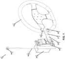
- the robot 5 includes an actuator 20 (illustrated as a servo) mounted to the automobile.
- the actuator may be housed in a bracket 35 that has a bracing rod 40 extending therefrom.
- a bracing rod mount 45 At the end of the bracing rod is a bracing rod mount 45 that connects to an automobile mount 100, shown in FIGS. 7-11 .
- a non-limiting example of the automobile mount is a suction cup that may connect to the test automobile's windshield.
- a connection structure - i.e., actuator arm 25A - is connected to the actuator 20 which has an electromechanical connector 30 that temporarily connects the actuator arm 25A to the steering wheel 10.
- the steering wheel 10 may have a lightweight steering wheel bracket 15 that is the connection point to the electromechanical connector 30.
- the actuator arm 25A is depicted as a longitudinal rod, but it need not be so; rather the actuator arm 25A may be used to amplify the rotational movement of the actuator 20 by connecting the to the rotational axis of the actuator 20 at one location on the actuator arm 25A and connecting to the electromechanical connector 30 at another location on the actuator arm 25A. Therefore, the actuator arm 25A may be shaped more like a plate if necessary. Further the actuator arm 25A need not be used; rather the actuator 20 may be connected to the steering wheel through other types of connection structures such a shaft, discussed in more detail below with respect to FIGS. 12A through 12D .
- a steering processor 75 is connected to the actuator 20 and electromechanical connector 30 and can control them both.
- the processor 75 can operate the steering wheel 10 when the actuator 20 is connected to the steering wheel 10 by way of the electromechanical connector 30. This is shown by the robotic steering rotation 50 in FIG. 2 and the opposite robotic steering rotation 55 in FIG. 3 .
- the processor 75 can disconnect 60 the actuator 20 from the steering wheel 10 as shown in FIG. 4A .
- the processor may perform the actuation of the actuator 20 and then the actuation of the electromechanical connector 30 while the test automobile is being driven.
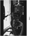
- FIGS. 7 through 11 illustrate the installation of the steering robot 5 on a test automobile. Further FIGS. 8 , 9 and 10 , show the decoupling of the electromechanical connector 30 from the steering wheel 10, each of these figures are illustrated fractions of a second apart from each other.
- a compliant coupling 27 between the end of the actuator arm 25A and the attachment to the steering wheel 10 is optional.
- Some LKS systems determine driver attentiveness/alertness by monitoring steering wheel torque and angular variations.
- a rigid coupling between the actuator arm 25A and the steering wheel 10 can be interpreted as an attentive driver, which may cause the LKS to suppress certain features and functions, including steering intervention, and adversely affect the evaluation of the LKS.
- a compliant coupling 27 can be interpreted as a less attentive driver, such that the LKS will not suppress steering interventions.
- the compliant coupling 27 may further include an adjustable spring rate and preload, such that the compliance of the coupling can be tailored to suit the requirements of the evaluation.
- the actuator 20 including the actuator arm 25A, move away from the steering wheel 10 so as to prevent any interference with the steering wheel 10.
- the robot 5 and the actuator 20 may experience an actuator detachment force 65, but the connection of the actuator 20 to the steering wheel 10 by way of the electromechanical connector 30 is sufficient to overcome the force.
- Actuating the electromechanical connector 30 causes the actuator detachment force 65 to move the actuator 20 away from the steering wheel 60 as shown in FIG. 4A .
- the detachment force may be gravity 65A, a rotational spring bias 65B, a translational spring bias 65C, or combinations thereof as shown in FIG. 4B .
- FIG. 11 also illustrates the actuator detachment 60 from the steering wheel bracket 15, which is caused by the actuator detachment force 65.
- the steering robot 5 Because the steering robot 5 and has mass, it also has self-inertia. Its self-inertia provides inertial loading when it is connected to the steering wheel.
- the actuator 20 also has internal resistance to rotation, and this is experienced in the form of a drag force when it is connected to the steering wheel. These happen even when the steering robot 5 is turned off or deactivated. Because the test automobile's safety features attempt to direct the car in a safe direction, but can be overcome by a driver's slight torque on the steering wheel, this inertia and drag can skew the evaluation of the test automobiles safety features.
- the steering wheel should have as little external inertia and drag as possible to have a useful and unbiased evaluation. When the currently steering robot 5 actuates the electromechanical connector 30, the steering wheel 10 is decoupled from the external inertia and drag, allowing for the more accurate evaluation.
- FIG. 5A illustrates an electromechanical connector that is an electromagnet 30A and attracted to a steering wheel bracket connection structure -i.e. a piece of metal 15AA - that is part of the steering wheel bracket 15A.
- Actuating the electromechanical connector 30A comprises deactivation 70A of the electromagnet 30A such that the electromagnet 30A is not attracted to the piece of metal 15AA causing actuator arm detachment 60.
- FIG. 5B and 5C illustrate electromechanical connectors that include a pin (30B, 30C) inserted into steering wheel bracket connection structures - i.e., slots (15BB, 15CC) - that are a part of the steering wheel brackets (15B, 15C). Actuating the electromechanical connectors (30B, 30C) removes the pin (70B, 70C) from the slots (15BB, 15CC).
- FIG. 5D illustrates an actuator arm 25A with an electromechanical connector that is a pincer 30D that can be actuated 70D to open and release from the steering wheel 10.
- the actuator 20 is situated to the side of the steering wheel 10, such that its rotational axis is parallel to, but not coincident with, the rotational axis of the steering wheel 10.
- the electromechanical connector 30 may be situated on the forward side of the steering wheel 10 (i.e., the side opposite the driver) such that it can fall away from the steering wheel 10 under its own weight upon disconnect.
- the rotational plane of the actuator is not necessarily equal to the rotational plane of the steering wheel. This is shown in FIG. 11 where the rotational plane of the actuator when connected to the steering wheel 10 is shown as line 105, and the rotational plane of the steering wheel 10 is shown as line 110.
- trigonometric compensation must be applied to achieve the desired steering wheel angle, based upon the geometry of the particular installation.
- the actuator 20 is situated over the steering wheel 10, such that its rotational axis is coincident with the rotational axis of the steering wheel.
- the electromechanical connector 30 is situated on the rear side of the steering wheel 10 (i.e., the side nearest the driver).
- the structures disclosed in FIG. 4B may be used to accomplish this.
- the actuator angle is equal to the steering wheel angle, and no additional angular compensation may be necessary.
- FIG. 6 illustrates a schematic of the processor control of the actuator 20 and the electromechanical connector 30.
- the steering processor 75 is connected to the actuator 20 via control line 95 and to the electromechanical connector via control line 90. While these lines may be hardwired, they also may be wireless.
- the test automobile may also have an automobile processor 80 connected to automobile sensors.
- the steering processor 75 may be connected to the automobile processor 80.
- the operation of the steering robot may be accomplished either fully or partially by a remote control 85 connected to the steering processor 75 through a wireless signal.
- the remote control may be external to the test automobile.
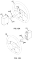
- FIGS. 12A and 12B illustrate the use of an actuator shaft 25B as the connection structure.
- the actuator 20 is connected to an actuator shaft 25B that has the electromechanical connector 30E that engages a steering wheel bracket (shaft coupler) 15D connected to the steering wheel 10.
- the electromechanical connector 30E and the steering wheel bracket (shaft coupler) 15D may have complementary teeth structures to allow for high torque of the actuator 20 without the connection between the actuator 20 and the steering wheel 10 experiencing slippage.
- the electromechanical connector 30E may be an electromagnet that maintains the actuator shaft in connection with the steering wheel bracket (shaft coupler) 15D.
- FIGS. 12C and 12D illustrate electromechanical connectors for the actuator shaft 25B.
- FIG. 12C illustrates an electromechanical connector that is an electromagnet 30E attracted to a steering wheel bracket connection structure -i.e. a piece of metal 15DD - that is part of the steering wheel bracket (shaft coupler) 15D.
- Actuating the electromechanical connector 30E comprises deactivation 70E of the electromagnet 30E such that the electromagnet 30E is not attracted to the piece of metal 15DD causing actuator shaft detachment 60.
- FIG. 12D illustrates electromechanical connector that includes a pin 3 OF inserted into steering wheel bracket connection structures slot 15EE that is a part of the steering wheel bracket 15E. Actuating the electromechanical connector 30F removes the pin 70F from the slot 15EE.
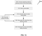
- FIG. 13 is illustrates a method 200 of evaluating the free response of a test automobile's safety functions using the steering robot.
- a steering robot is connected to a steering wheel of the test automobile, the robot having its own inertia such that the inertia is coupled to the steering wheel.
- the test automobile is driven (step 210) and while driven the robot is actuated to operate the steering wheel at step 215. This actuation may be sufficient to direct the test automobile out of its current driving lane.
- the robot decouples from the steering wheel thereby decoupling its own inertia from the steering wheel in step 220. Now the results of the free response of a test automobile's safety functions may be evaluated at step 225.
- the operation of the steering robot could be performed remotely (step 230).
- the robot used in method 200 may be the steering robot 5 detailed above.
- the test automobile's safety functions may include, but are not limited to, a lane keeping system, an autonomous driving system and a semi-autonomous driving system.
Landscapes
- Engineering & Computer Science (AREA)
- Chemical & Material Sciences (AREA)
- Combustion & Propulsion (AREA)
- Transportation (AREA)
- Mechanical Engineering (AREA)
- Radar, Positioning & Navigation (AREA)
- Aviation & Aerospace Engineering (AREA)
- Remote Sensing (AREA)
- Physics & Mathematics (AREA)
- General Physics & Mathematics (AREA)
- Automation & Control Theory (AREA)
- Steering Control In Accordance With Driving Conditions (AREA)
- Manipulator (AREA)
- Automobile Manufacture Line, Endless Track Vehicle, Trailer (AREA)
Claims (15)
- Robot de direction (5) permettant de faire fonctionner un volant de direction (10) d'une automobile d'essai, le robot (5) comprenant :un actionneur (20) monté sur l'automobile ;un connecteur électromécanique (30, 30A, 30B, 30C, 30D, 30E, 30F) qui connecte de manière amovible l'actionneur (20) au volant de direction (10) ; etun processeur de direction (75) connecté à l'actionneur (20) et au connecteur électromécanique (30, 30A, 30B, 30C, 30D, 30E, 30F), le processeur de direction (75) étant adapté pour effectuer l'étape consistant à :(1) actionner l'actionneur (215), en faisant ainsi fonctionner le volant de direction lorsque l'actionneur est connecté au volant de direction au moyen du connecteur électromécanique ; caractérisé en ce que le processeur de direction (75) est adapté pour effectuer l'étape consistant à :(2) actionner le connecteur électromécanique (220), en déconnectant ainsi l'actionneur à partir du volant de direction.
- Robot de direction selon la revendication 1, comprenant en outre une structure de connexion (25) qui transfère un couple de l'actionneur (20) au volant de direction (10), la structure de connexion (25) étant sélectionnée dans un groupe constitué de : un bras d'actionneur, un arbre et une plaque.
- Robot de direction selon la revendication 1, dans lequel le connecteur électromécanique (30A) comprend un électroaimant attiré vers une pièce de métal.
- Robot de direction selon la revendication 1, dans lequel le connecteur électromécanique (30B, 30C) comprend une broche insérée dans une fente.
- Robot de direction selon la revendication 1, dans lequel l'actionneur (20) subit une force de détachement d'actionneur (65), et dans lequel la connexion de l'actionneur (20) au volant de direction (10) est suffisante pour surmonter la force, et dans lequel l'actionnement du connecteur électromécanique amène la force de détachement d'actionneur à éloigner le connecteur électromécanique du volant de direction.
- Robot de direction selon la revendication 5, dans lequel la force de détachement (65) est sélectionnée dans le groupe constitué de : gravité (65A), sollicitation de ressort de rotation (65B), sollicitation de ressort de translation (65C), et des combinaisons de celles-ci.
- Robot de direction selon la revendication 1, dans lequel l'automobile d'essai comprend un processeur d'automobile (80) connecté à des capteurs d'automobile, dans lequel le processeur de direction (75) est connecté au processeur d'automobile (80).
- Robot de direction selon la revendication 1, comprenant en outre une commande à distance (85) connectée au processeur de direction (75) via un signal sans fil.
- Robot de direction selon la revendication 1, dans lequel le robot (5) présente une auto-inertie et lorsque le robot (5) est connecté au volant de direction (10), le volant de direction (10) subit l'auto-inertie du robot et dans lequel l'actionnement du connecteur électromécanique (30, 30A, 30B, 30C, 30D, 30E, 30F) désaccouple l'auto-inertie du robot à partir du volant de direction (10).
- Robot de direction selon la revendication 1, dans lequel le processeur (75) exécute l'étape (1) puis l'étape (2) pendant que l'automobile d'essai se déplace.
- Robot de direction selon la revendication 1, dans lequel l'actionneur (20) est sélectionné dans un type consistant en : hydraulique, pneumatique, mécanique, électrique, thermique, magnétique, sous vide, et des combinaisons de ceux-ci.
- Procédé (200) pour essayer des fonctions de sécurité d'automobile d'essai, le procédé (200) comprenant les étapes consistant à :a. fournir (205) un robot de direction (5) connecté à un volant de direction (10) de l'automobile d'essai, le robot (5) présentant une inertie, l'inertie étant couplée au volant de direction (10) ;b. conduire l'automobile d'essai (210) ;c. pendant la conduite, actionner le robot pour faire fonctionner le volant de direction (215) ; caractérisé par les étapes consistant à :d. lors de la conduite, désaccoupler (220) le robot (5) à partir du volant de direction (10), en désaccouplant ainsi l'inertie à partir du volant de direction (10) ; ete. évaluer les fonctions de sécurité d'automobile (225) .
- Procédé (200) selon la revendication 12, dans lequel :le robot comprend un actionneur (20) monté sur l'automobile, et un connecteur électromécanique (30, 30A, 30B, 30C, 30D, 30E, 30F) qui connecte de manière amovible l'actionneur (20) au volant de direction (10) ;l'étape (c) comprend un actionnement de l'actionneur (20) et ainsi un fonctionnement du volant de direction (10) ; etl'étape (d) consiste à actionner le connecteur électromécanique (30, 30A, 30B, 30C, 30D, 30E, 30F) et à déconnecter ainsi l'actionneur (20) à partir du volant (10).
- Procédé (200) selon la revendication 12, dans lequel la fonction de sécurité d'automobile est sélectionnée dans un groupe consistant en : un système de maintien de voie, un système de conduite autonome ou un système de conduite semi-autonome.
- Procédé (200) selon la revendication 12, dans lequel les étapes (c) et (d) sont commandées par un processeur (75, 85).
Applications Claiming Priority (3)
| Application Number | Priority Date | Filing Date | Title |
|---|---|---|---|
| US201762539652P | 2017-08-01 | 2017-08-01 | |
| US15/671,976 US10585429B2 (en) | 2017-08-01 | 2017-08-08 | Robotic steering controller for optimal free response evaluation |
| PCT/US2018/042139 WO2019027658A1 (fr) | 2017-08-01 | 2018-07-13 | Dispositif de commande de direction robotique pour évaluation de réponse libre optimale |
Publications (3)
| Publication Number | Publication Date |
|---|---|
| EP3661825A1 EP3661825A1 (fr) | 2020-06-10 |
| EP3661825A4 EP3661825A4 (fr) | 2021-04-14 |
| EP3661825B1 true EP3661825B1 (fr) | 2022-01-19 |
Family
ID=65229969
Family Applications (1)
| Application Number | Title | Priority Date | Filing Date |
|---|---|---|---|
| EP18842272.9A Active EP3661825B1 (fr) | 2017-08-01 | 2018-07-13 | Dispositif de commande de direction robotique pour évaluation de réponse libre optimale |
Country Status (4)
| Country | Link |
|---|---|
| US (1) | US10585429B2 (fr) |
| EP (1) | EP3661825B1 (fr) |
| ES (1) | ES2906703T3 (fr) |
| WO (1) | WO2019027658A1 (fr) |
Cited By (1)
| Publication number | Priority date | Publication date | Assignee | Title |
|---|---|---|---|---|
| US11820356B2 (en) | 2019-12-20 | 2023-11-21 | Humanetics Austria Gmbh | System and method for force compensation in a robotic driving system |
Families Citing this family (4)
| Publication number | Priority date | Publication date | Assignee | Title |
|---|---|---|---|---|
| GB2596332B (en) * | 2020-06-25 | 2024-01-10 | Anthony Best Dynamics Ltd | A steering wheel actuation device and method for vehicle testing |
| HU231511B1 (hu) * | 2021-07-09 | 2024-05-28 | Aimotive Kft | Kormányzási rendszer autonóm jármű teszt vezetéséhez való használatra, leválasztási eljárás és adatfeldolgozó rendszer, számítógépes programtermék és számítógéppel olvasható tárolóeszköz az eljárás megvalósításához |
| CN114684243B (zh) * | 2022-02-24 | 2023-01-13 | 智己汽车科技有限公司 | 一种方向盘及具备该方向盘的车辆 |
| CN115032477A (zh) * | 2022-04-27 | 2022-09-09 | 中机寰宇(山东)车辆认证检测有限公司 | Emc试验室汽车转向性能测试机器人 |
Family Cites Families (16)
| Publication number | Priority date | Publication date | Assignee | Title |
|---|---|---|---|---|
| US3007709A (en) * | 1957-03-15 | 1961-11-07 | Clark J R Co | Collapsible utility cart |
| ATE42831T1 (de) * | 1986-03-04 | 1989-05-15 | Schenck Ag Carl | Bezugsplattform fuer eine arretierbare aufstellung. |
| US5020754A (en) * | 1990-01-22 | 1991-06-04 | Valentine Research, Inc. | Method and apparatus for mounting radar detector |
| US6437771B1 (en) * | 1995-01-18 | 2002-08-20 | Immersion Corporation | Force feedback device including flexure member between actuator and user object |
| GB2417090A (en) * | 2003-04-28 | 2006-02-15 | Stephen James Crampton | CMM arm with exoskeleton |
| FR2872452B1 (fr) * | 2004-07-02 | 2006-09-22 | Michelin Soc Tech | Dispositif de suspension pour vehicule automobile |
| AU2006306523B2 (en) * | 2005-10-21 | 2011-05-19 | Deere & Company | Systems and methods for switching between autonomous and manual operation of a vehicle |
| WO2007149559A2 (fr) * | 2006-06-22 | 2007-12-27 | Board Of Regents Of The University Of Nebraska | dispositifs robotiques pouvant être couplés magnétiquement et procédés associés |
| CN101246133B (zh) * | 2007-02-16 | 2011-07-20 | 同方威视技术股份有限公司 | 方向纠偏设备和方法及移动式辐射检查系统 |
| DE102009017714A1 (de) * | 2009-04-09 | 2011-01-13 | Takata-Petri Ag | Lenkrad für ein Kraftfahrzeug mit Überlagerungslenkung |
| DE102010036891A1 (de) * | 2010-06-28 | 2011-12-29 | Thyssenkrupp Presta Ag | Verstellbare Lenksäule für ein Kraftfahrzeug |
| CN103620928A (zh) * | 2011-03-17 | 2014-03-05 | 联合活跃驱动公司 | 多个同步振动致动器的非对称总体振动波形 |
| US8447509B2 (en) * | 2011-07-13 | 2013-05-21 | Dynamic Research, Inc. | System and method for testing crash avoidance technologies |
| US20130061558A1 (en) * | 2011-09-12 | 2013-03-14 | Michael KLEAR | Multiple robot system |
| US10379007B2 (en) * | 2015-06-24 | 2019-08-13 | Perrone Robotics, Inc. | Automated robotic test system for automated driving systems |
| US10104827B2 (en) * | 2015-07-08 | 2018-10-23 | The Royal Institution For The Advancement Of Learning/Mcgill University | Guidance system and steering control device for an agricultural vehicle |
-
2017
- 2017-08-08 US US15/671,976 patent/US10585429B2/en active Active
-
2018
- 2018-07-13 ES ES18842272T patent/ES2906703T3/es active Active
- 2018-07-13 EP EP18842272.9A patent/EP3661825B1/fr active Active
- 2018-07-13 WO PCT/US2018/042139 patent/WO2019027658A1/fr not_active Ceased
Cited By (2)
| Publication number | Priority date | Publication date | Assignee | Title |
|---|---|---|---|---|
| US11820356B2 (en) | 2019-12-20 | 2023-11-21 | Humanetics Austria Gmbh | System and method for force compensation in a robotic driving system |
| US12472920B2 (en) | 2019-12-20 | 2025-11-18 | Humanetics Austria Gmbh | System and method for force compensation in a robotic driving system |
Also Published As
| Publication number | Publication date |
|---|---|
| EP3661825A1 (fr) | 2020-06-10 |
| US10585429B2 (en) | 2020-03-10 |
| EP3661825A4 (fr) | 2021-04-14 |
| ES2906703T3 (es) | 2022-04-20 |
| WO2019027658A1 (fr) | 2019-02-07 |
| US20190041847A1 (en) | 2019-02-07 |
Similar Documents
| Publication | Publication Date | Title |
|---|---|---|
| EP3661825B1 (fr) | Dispositif de commande de direction robotique pour évaluation de réponse libre optimale | |
| JP7394953B2 (ja) | 交換可能な駆動モジュールを有する車両および駆動モジュール | |
| EP3283349B1 (fr) | Système et procédé de direction pour véhicules autonomes | |
| US12515749B2 (en) | Vehicle corner modules and systems and methods for installation thereof | |
| CN110114254B (zh) | 在自动变道期间减小横向位置偏差 | |
| CN110901761B (zh) | 线控转向系统和用于估计线控转向系统的齿条力的方法 | |
| US7174987B2 (en) | End of travel feature for steer by wire vehicle | |
| CN109789892B (zh) | 用于自动驾驶的冗余转向控制装置 | |
| EP4140839B1 (fr) | Commande de véhicule basé sur une limite de dérapage configurée de manière dynamique | |
| US7762567B2 (en) | Steering system and method for steering a vehicle | |
| CN107709139A (zh) | 具有前桥转向系统和后桥转向系统的自动驾驶的机动车 | |
| WO2001072571A3 (fr) | Direction de vehicule et module de direction pour direction de vehicule | |
| CN102574545A (zh) | 汽车中的转向系统 | |
| CN106458160A (zh) | 刮水器设备 | |
| EP2604495A1 (fr) | Procédé et dispositif de contrôle du mouvement d'un véhicule articulé | |
| CN103291878A (zh) | 限滑差速器的电子控制 | |
| JP5386132B2 (ja) | 操舵支援装置 | |
| US6942058B2 (en) | Vehicle steering system for kickback reduction | |
| US11919582B2 (en) | Methods, systems, and apparatuses for real-time adaptation of handwheel angle controls for robust automated driving to environmental conditions and model uncertainties | |
| JP2007326499A (ja) | 操舵装置 | |
| CN117162927A (zh) | 传感器总成和安装到车辆的方法 | |
| CN222040551U (zh) | 一种分布式智能汽车方向盘转向辅助装置 | |
| US12472952B2 (en) | Vehicle including a vehicle platform that transitions to a wake mode according to a wake command | |
| EP4015366B1 (fr) | Procédés et systèmes de surpassement de commande autonome de dispositif | |
| KR20120127948A (ko) | 차량용 틸트 및 텔레스코픽 스티어링장치의 제어방법 |
Legal Events
| Date | Code | Title | Description |
|---|---|---|---|
| STAA | Information on the status of an ep patent application or granted ep patent |
Free format text: STATUS: THE INTERNATIONAL PUBLICATION HAS BEEN MADE |
|
| PUAI | Public reference made under article 153(3) epc to a published international application that has entered the european phase |
Free format text: ORIGINAL CODE: 0009012 |
|
| STAA | Information on the status of an ep patent application or granted ep patent |
Free format text: STATUS: REQUEST FOR EXAMINATION WAS MADE |
|
| 17P | Request for examination filed |
Effective date: 20200227 |
|
| AK | Designated contracting states |
Kind code of ref document: A1 Designated state(s): AL AT BE BG CH CY CZ DE DK EE ES FI FR GB GR HR HU IE IS IT LI LT LU LV MC MK MT NL NO PL PT RO RS SE SI SK SM TR |
|
| AX | Request for extension of the european patent |
Extension state: BA ME |
|
| DAV | Request for validation of the european patent (deleted) | ||
| DAX | Request for extension of the european patent (deleted) | ||
| A4 | Supplementary search report drawn up and despatched |
Effective date: 20210317 |
|
| RIC1 | Information provided on ipc code assigned before grant |
Ipc: B62D 15/02 20060101AFI20210311BHEP Ipc: B62D 1/00 20060101ALI20210311BHEP |
|
| REG | Reference to a national code |
Ref country code: DE Ref legal event code: R079 Ref document number: 602018029893 Country of ref document: DE Free format text: PREVIOUS MAIN CLASS: B60W0010200000 Ipc: B62D0015020000 |
|
| GRAP | Despatch of communication of intention to grant a patent |
Free format text: ORIGINAL CODE: EPIDOSNIGR1 |
|
| STAA | Information on the status of an ep patent application or granted ep patent |
Free format text: STATUS: GRANT OF PATENT IS INTENDED |
|
| RIC1 | Information provided on ipc code assigned before grant |
Ipc: B62D 1/00 20060101ALI20210830BHEP Ipc: B62D 15/02 20060101AFI20210830BHEP |
|
| INTG | Intention to grant announced |
Effective date: 20210915 |
|
| GRAS | Grant fee paid |
Free format text: ORIGINAL CODE: EPIDOSNIGR3 |
|
| GRAA | (expected) grant |
Free format text: ORIGINAL CODE: 0009210 |
|
| STAA | Information on the status of an ep patent application or granted ep patent |
Free format text: STATUS: THE PATENT HAS BEEN GRANTED |
|
| AK | Designated contracting states |
Kind code of ref document: B1 Designated state(s): AL AT BE BG CH CY CZ DE DK EE ES FI FR GB GR HR HU IE IS IT LI LT LU LV MC MK MT NL NO PL PT RO RS SE SI SK SM TR |
|
| REG | Reference to a national code |
Ref country code: GB Ref legal event code: FG4D |
|
| REG | Reference to a national code |
Ref country code: CH Ref legal event code: EP |
|
| REG | Reference to a national code |
Ref country code: DE Ref legal event code: R096 Ref document number: 602018029893 Country of ref document: DE |
|
| REG | Reference to a national code |
Ref country code: AT Ref legal event code: REF Ref document number: 1463644 Country of ref document: AT Kind code of ref document: T Effective date: 20220215 |
|
| REG | Reference to a national code |
Ref country code: IE Ref legal event code: FG4D |
|
| REG | Reference to a national code |
Ref country code: SE Ref legal event code: TRGR |
|
| REG | Reference to a national code |
Ref country code: ES Ref legal event code: FG2A Ref document number: 2906703 Country of ref document: ES Kind code of ref document: T3 Effective date: 20220420 |
|
| REG | Reference to a national code |
Ref country code: LT Ref legal event code: MG9D |
|
| REG | Reference to a national code |
Ref country code: NL Ref legal event code: MP Effective date: 20220119 |
|
| PG25 | Lapsed in a contracting state [announced via postgrant information from national office to epo] |
Ref country code: NL Free format text: LAPSE BECAUSE OF FAILURE TO SUBMIT A TRANSLATION OF THE DESCRIPTION OR TO PAY THE FEE WITHIN THE PRESCRIBED TIME-LIMIT Effective date: 20220119 |
|
| PG25 | Lapsed in a contracting state [announced via postgrant information from national office to epo] |
Ref country code: RS Free format text: LAPSE BECAUSE OF FAILURE TO SUBMIT A TRANSLATION OF THE DESCRIPTION OR TO PAY THE FEE WITHIN THE PRESCRIBED TIME-LIMIT Effective date: 20220119 Ref country code: PT Free format text: LAPSE BECAUSE OF FAILURE TO SUBMIT A TRANSLATION OF THE DESCRIPTION OR TO PAY THE FEE WITHIN THE PRESCRIBED TIME-LIMIT Effective date: 20220519 Ref country code: NO Free format text: LAPSE BECAUSE OF FAILURE TO SUBMIT A TRANSLATION OF THE DESCRIPTION OR TO PAY THE FEE WITHIN THE PRESCRIBED TIME-LIMIT Effective date: 20220419 Ref country code: LT Free format text: LAPSE BECAUSE OF FAILURE TO SUBMIT A TRANSLATION OF THE DESCRIPTION OR TO PAY THE FEE WITHIN THE PRESCRIBED TIME-LIMIT Effective date: 20220119 Ref country code: HR Free format text: LAPSE BECAUSE OF FAILURE TO SUBMIT A TRANSLATION OF THE DESCRIPTION OR TO PAY THE FEE WITHIN THE PRESCRIBED TIME-LIMIT Effective date: 20220119 Ref country code: BG Free format text: LAPSE BECAUSE OF FAILURE TO SUBMIT A TRANSLATION OF THE DESCRIPTION OR TO PAY THE FEE WITHIN THE PRESCRIBED TIME-LIMIT Effective date: 20220419 |
|
| PG25 | Lapsed in a contracting state [announced via postgrant information from national office to epo] |
Ref country code: PL Free format text: LAPSE BECAUSE OF FAILURE TO SUBMIT A TRANSLATION OF THE DESCRIPTION OR TO PAY THE FEE WITHIN THE PRESCRIBED TIME-LIMIT Effective date: 20220119 Ref country code: LV Free format text: LAPSE BECAUSE OF FAILURE TO SUBMIT A TRANSLATION OF THE DESCRIPTION OR TO PAY THE FEE WITHIN THE PRESCRIBED TIME-LIMIT Effective date: 20220119 Ref country code: GR Free format text: LAPSE BECAUSE OF FAILURE TO SUBMIT A TRANSLATION OF THE DESCRIPTION OR TO PAY THE FEE WITHIN THE PRESCRIBED TIME-LIMIT Effective date: 20220420 Ref country code: FI Free format text: LAPSE BECAUSE OF FAILURE TO SUBMIT A TRANSLATION OF THE DESCRIPTION OR TO PAY THE FEE WITHIN THE PRESCRIBED TIME-LIMIT Effective date: 20220119 |
|
| PG25 | Lapsed in a contracting state [announced via postgrant information from national office to epo] |
Ref country code: IS Free format text: LAPSE BECAUSE OF FAILURE TO SUBMIT A TRANSLATION OF THE DESCRIPTION OR TO PAY THE FEE WITHIN THE PRESCRIBED TIME-LIMIT Effective date: 20220519 |
|
| REG | Reference to a national code |
Ref country code: DE Ref legal event code: R097 Ref document number: 602018029893 Country of ref document: DE |
|
| PG25 | Lapsed in a contracting state [announced via postgrant information from national office to epo] |
Ref country code: SM Free format text: LAPSE BECAUSE OF FAILURE TO SUBMIT A TRANSLATION OF THE DESCRIPTION OR TO PAY THE FEE WITHIN THE PRESCRIBED TIME-LIMIT Effective date: 20220119 Ref country code: SK Free format text: LAPSE BECAUSE OF FAILURE TO SUBMIT A TRANSLATION OF THE DESCRIPTION OR TO PAY THE FEE WITHIN THE PRESCRIBED TIME-LIMIT Effective date: 20220119 Ref country code: RO Free format text: LAPSE BECAUSE OF FAILURE TO SUBMIT A TRANSLATION OF THE DESCRIPTION OR TO PAY THE FEE WITHIN THE PRESCRIBED TIME-LIMIT Effective date: 20220119 Ref country code: EE Free format text: LAPSE BECAUSE OF FAILURE TO SUBMIT A TRANSLATION OF THE DESCRIPTION OR TO PAY THE FEE WITHIN THE PRESCRIBED TIME-LIMIT Effective date: 20220119 Ref country code: DK Free format text: LAPSE BECAUSE OF FAILURE TO SUBMIT A TRANSLATION OF THE DESCRIPTION OR TO PAY THE FEE WITHIN THE PRESCRIBED TIME-LIMIT Effective date: 20220119 Ref country code: CZ Free format text: LAPSE BECAUSE OF FAILURE TO SUBMIT A TRANSLATION OF THE DESCRIPTION OR TO PAY THE FEE WITHIN THE PRESCRIBED TIME-LIMIT Effective date: 20220119 |
|
| PLBE | No opposition filed within time limit |
Free format text: ORIGINAL CODE: 0009261 |
|
| STAA | Information on the status of an ep patent application or granted ep patent |
Free format text: STATUS: NO OPPOSITION FILED WITHIN TIME LIMIT |
|
| PG25 | Lapsed in a contracting state [announced via postgrant information from national office to epo] |
Ref country code: AL Free format text: LAPSE BECAUSE OF FAILURE TO SUBMIT A TRANSLATION OF THE DESCRIPTION OR TO PAY THE FEE WITHIN THE PRESCRIBED TIME-LIMIT Effective date: 20220119 |
|
| 26N | No opposition filed |
Effective date: 20221020 |
|
| PG25 | Lapsed in a contracting state [announced via postgrant information from national office to epo] |
Ref country code: SI Free format text: LAPSE BECAUSE OF FAILURE TO SUBMIT A TRANSLATION OF THE DESCRIPTION OR TO PAY THE FEE WITHIN THE PRESCRIBED TIME-LIMIT Effective date: 20220119 Ref country code: MC Free format text: LAPSE BECAUSE OF FAILURE TO SUBMIT A TRANSLATION OF THE DESCRIPTION OR TO PAY THE FEE WITHIN THE PRESCRIBED TIME-LIMIT Effective date: 20220119 |
|
| REG | Reference to a national code |
Ref country code: CH Ref legal event code: PL |
|
| REG | Reference to a national code |
Ref country code: BE Ref legal event code: MM Effective date: 20220731 |
|
| PG25 | Lapsed in a contracting state [announced via postgrant information from national office to epo] |
Ref country code: LU Free format text: LAPSE BECAUSE OF NON-PAYMENT OF DUE FEES Effective date: 20220713 Ref country code: LI Free format text: LAPSE BECAUSE OF NON-PAYMENT OF DUE FEES Effective date: 20220731 Ref country code: CH Free format text: LAPSE BECAUSE OF NON-PAYMENT OF DUE FEES Effective date: 20220731 |
|
| PG25 | Lapsed in a contracting state [announced via postgrant information from national office to epo] |
Ref country code: BE Free format text: LAPSE BECAUSE OF NON-PAYMENT OF DUE FEES Effective date: 20220731 |
|
| REG | Reference to a national code |
Ref country code: AT Ref legal event code: UEP Ref document number: 1463644 Country of ref document: AT Kind code of ref document: T Effective date: 20220119 |
|
| P01 | Opt-out of the competence of the unified patent court (upc) registered |
Effective date: 20230529 |
|
| PG25 | Lapsed in a contracting state [announced via postgrant information from national office to epo] |
Ref country code: IT Free format text: LAPSE BECAUSE OF FAILURE TO SUBMIT A TRANSLATION OF THE DESCRIPTION OR TO PAY THE FEE WITHIN THE PRESCRIBED TIME-LIMIT Effective date: 20220119 Ref country code: IE Free format text: LAPSE BECAUSE OF NON-PAYMENT OF DUE FEES Effective date: 20220713 |
|
| PG25 | Lapsed in a contracting state [announced via postgrant information from national office to epo] |
Ref country code: MK Free format text: LAPSE BECAUSE OF FAILURE TO SUBMIT A TRANSLATION OF THE DESCRIPTION OR TO PAY THE FEE WITHIN THE PRESCRIBED TIME-LIMIT Effective date: 20220119 Ref country code: CY Free format text: LAPSE BECAUSE OF FAILURE TO SUBMIT A TRANSLATION OF THE DESCRIPTION OR TO PAY THE FEE WITHIN THE PRESCRIBED TIME-LIMIT Effective date: 20220119 |
|
| PG25 | Lapsed in a contracting state [announced via postgrant information from national office to epo] |
Ref country code: HU Free format text: LAPSE BECAUSE OF FAILURE TO SUBMIT A TRANSLATION OF THE DESCRIPTION OR TO PAY THE FEE WITHIN THE PRESCRIBED TIME-LIMIT; INVALID AB INITIO Effective date: 20180713 |
|
| PG25 | Lapsed in a contracting state [announced via postgrant information from national office to epo] |
Ref country code: TR Free format text: LAPSE BECAUSE OF FAILURE TO SUBMIT A TRANSLATION OF THE DESCRIPTION OR TO PAY THE FEE WITHIN THE PRESCRIBED TIME-LIMIT Effective date: 20220119 |
|
| PG25 | Lapsed in a contracting state [announced via postgrant information from national office to epo] |
Ref country code: MT Free format text: LAPSE BECAUSE OF FAILURE TO SUBMIT A TRANSLATION OF THE DESCRIPTION OR TO PAY THE FEE WITHIN THE PRESCRIBED TIME-LIMIT Effective date: 20220119 |
|
| PGFP | Annual fee paid to national office [announced via postgrant information from national office to epo] |
Ref country code: ES Payment date: 20250819 Year of fee payment: 8 |
|
| PGFP | Annual fee paid to national office [announced via postgrant information from national office to epo] |
Ref country code: DE Payment date: 20250728 Year of fee payment: 8 |
|
| PGFP | Annual fee paid to national office [announced via postgrant information from national office to epo] |
Ref country code: GB Payment date: 20250724 Year of fee payment: 8 |
|
| PGFP | Annual fee paid to national office [announced via postgrant information from national office to epo] |
Ref country code: FR Payment date: 20250723 Year of fee payment: 8 Ref country code: AT Payment date: 20250721 Year of fee payment: 8 |
|
| PGFP | Annual fee paid to national office [announced via postgrant information from national office to epo] |
Ref country code: SE Payment date: 20250723 Year of fee payment: 8 |