EP3661835B1 - Verfahren zur herstellung einer aufnahme aus aluminium mit lastenverteilung über die flügel der rückverlängerungen für ein fahrzeug - Google Patents
Verfahren zur herstellung einer aufnahme aus aluminium mit lastenverteilung über die flügel der rückverlängerungen für ein fahrzeug Download PDFInfo
- Publication number
- EP3661835B1 EP3661835B1 EP18752546.4A EP18752546A EP3661835B1 EP 3661835 B1 EP3661835 B1 EP 3661835B1 EP 18752546 A EP18752546 A EP 18752546A EP 3661835 B1 EP3661835 B1 EP 3661835B1
- Authority
- EP
- European Patent Office
- Prior art keywords
- transverse
- interface zone
- define
- parallel
- machined
- Prior art date
- Legal status (The legal status is an assumption and is not a legal conclusion. Google has not performed a legal analysis and makes no representation as to the accuracy of the status listed.)
- Active
Links
Images
Classifications
-
- B—PERFORMING OPERATIONS; TRANSPORTING
- B62—LAND VEHICLES FOR TRAVELLING OTHERWISE THAN ON RAILS
- B62D—MOTOR VEHICLES; TRAILERS
- B62D21/00—Understructures, i.e. chassis frame on which a vehicle body may be mounted
- B62D21/11—Understructures, i.e. chassis frame on which a vehicle body may be mounted with resilient means for suspension, e.g. of wheels or engine; sub-frames for mounting engine or suspensions
-
- B—PERFORMING OPERATIONS; TRANSPORTING
- B62—LAND VEHICLES FOR TRAVELLING OTHERWISE THAN ON RAILS
- B62D—MOTOR VEHICLES; TRAILERS
- B62D29/00—Superstructures, understructures, or sub-units thereof, characterised by the material thereof
- B62D29/008—Superstructures, understructures, or sub-units thereof, characterised by the material thereof predominantly of light alloys, e.g. extruded
Definitions
- the invention relates to aluminum cradles, manufactured by extrusion (or extrusion), machining and welding (or fitting), and intended to equip certain vehicles, possibly of the automobile type, and more precisely the manufacture of such cradles.
- Certain vehicles generally of the automobile type, generally include in their front part an aluminum cradle, an example of which is illustrated on the figure 1 .
- the direction X is the longitudinal direction of the vehicle, which is substantially parallel to the lateral sides comprising the side doors
- the direction Y is the transverse direction of the vehicle, which is perpendicular to the direction X
- the direction Z is the vertical direction of the vehicle, which is perpendicular to the longitudinal X and transverse Y directions.
- a BA cradle comprises an extruded, machined TB cross member intended to be installed in a vehicle in the transverse direction Y, and comprising two opposite ends between them and to each of which are fixedly secured a front anchoring part (or “horn” ) PAV and a rear extension (or clevis) PB.
- the cross member TB comprises two transverse ends ET (opposite to each other) and a transverse partition CT extruded in the transverse direction Y.
- the front anchoring of the BA cradle on the body of a vehicle is done by means of the two front anchoring parts PAV, right and left.
- Each front anchor part PAV is extruded in the transverse direction Y and comprises lower PI and upper PS parts extending mutually.
- Each lower part PI is secured fixed to one of the two ends of the cross member TB via weld seams and comprises two vertical walls PV provided with holes defining a first anchoring point PA1 (generally called E1), along the longitudinal direction X, for example for the 'anchoring of a front part of a wheel triangle (or suspension) via a screw.
- Each upper part PS comprises holes defining a second vertical anchoring point PA2 (generally called X2) and intended to be traversed by a screw coupled to a part of the body.
- Each rear extension PB is extruded in the longitudinal direction X and machined to include a longitudinal partition CL extended by upper AS and lower AI wings, substantially horizontal and provided with holes which define a third anchor point PA3 (generally called E2) , in the vertical direction Z, for example for anchoring a rear part of a wheel triangle.
- E2 third anchor point PA3
- each ET transverse end of the TB cross member can be pre-machined.
- each ET transverse end can be pre-machined by means of a milling saw (for example having a disc with a diameter of 250 mm or 300 mm) whose milling axis is perpendicular to the XZ plane.
- a production method comprising a first machining step and a second welding step.
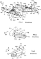
- each front end EV is machined by means of a tool having a machining axis placed parallel to the vertical direction Z. This machining is carried out first of all along a first path parallel to the transverse direction Y (arrow F1 of the figure 2 ), to define a first interface zone ZI1 in a central part and an upper part.
- this machining is done along a second path initially parallel to the direction transverse Y (arrow F2 of the figure 3 ), then curved in relation to the latter (arrow F3 of the figure 3 ), to define a second interface zone ZI2, extending rearwardly the first interface zone ZI1, in a lower part of the longitudinal partition CL and in the lower wing AI.
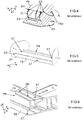
- each ET transverse end is machined by means of a tool having a machining axis placed parallel to the vertical direction Z with a path contained in the XY plane and then having a machining axis placed parallel to the transverse direction Y with a path contained in the XZ plane (see figure 6 ), to define in an upper part of its rear part a third interface zone ZI3 suitable for docking on the first interface zone ZI1.
- rear parts PR machined from the transverse ends AND of the cross member TB are welded respectively to the front ends EV of the two rear extensions PB. It is also possible to weld the machined PVT front parts of the transverse ends AND of the TB cross member respectively to the PAV front anchor parts.
- This method of the prior art offers relatively simple machining (two machining operations with the axis of the tool in the vertical direction Z for each rear extension PB, and two machining operations for each transverse end AND of the cross member TB).
- it induces a weakening of the lower wings of its rear extensions PB, which can cause cracks substantially along the longitudinal direction X in the lower wings AI.
- this reduction in the longitudinal extension of the lower wings AI relative to that of the upper wings AS causes an unbalanced distribution of the forces between these lower wings AI and these upper wings AS, which can induce cracking of the lower wings AI.
- the aim of the invention is therefore in particular to improve the situation.
- the lower wings and the longitudinal bulkheads being extended forward in the longitudinal direction, the docking between the cross member and the rear extensions and therefore significantly improved, which makes it possible to better distribute the forces between the lower and upper wings at the front ends of the rear extensions.
- the invention also proposes an aluminum cradle, intended to equip a vehicle, and produced by implementing a production method of the type of that presented above.
- the invention also proposes a vehicle, optionally of the automobile type, and comprising an aluminum cradle of the type of that presented above.
- this vehicle can also include two wheel triangles each comprising a front part secured to one of the front anchoring parts of the cradle, and a rear part secured to one of the rear extensions of the cradle.
- the object of the invention is in particular to propose a method intended to allow the production of an aluminum cradle BA with forces distributed over the wings AS and AI of the rear extensions PB and which must be fitted to a vehicle.
- the vehicle is of the automobile type. This is, for example, a car. But the invention is not limited to this type of vehicle. It relates in fact to any type of vehicle comprising an aluminum cradle intended to form part of a front axle assembly and possibly to participate in the support of wheel triangles and any other equipment, such as for example the steering, the anti-bar. -tilts, wheel assemblies by the triangle attachment and anti-roll bar link, exhaust support elements, or the soundproofing casing.
- an (aluminum) BA cradle comprises at least one cross member TB and two rear extensions (right and left) PB, as well as possibly two front anchoring pieces or horns ( right and left) PAV.
- the method according to the invention comprises a first machining step followed by a second welding step, described below.
- the cross member TB comprises two transverse ends ET (opposite to each other) and a transverse partition CT extruded in the transverse direction Y. It is machined and intended to be installed in a vehicle in the transverse direction Y.
- This cross member TB comprises two opposite ends to each other and to each of which are fixedly secured a rear extension (or clevis) PB and possibly a front anchoring piece (or horn) PAV.
- Each rear extension PB is extruded in the longitudinal direction X and machined to include a longitudinal partition CL extended by upper AS and lower AI wings, substantially horizontal and provided with holes which define a third anchor point PA3 (generally called E2) , in the vertical direction Z, for example for anchoring a rear part of a wheel triangle, via a screw or a bolt.
- E2 third anchor point PA3
- front and rear relate to the front end of the vehicle. Therefore, a front member is oriented towards the front end of the vehicle, while a rear member is oriented towards the rear end of the vehicle.
- the front anchoring of the BA cradle on the body of a vehicle can be done by means of the two front anchoring parts PAV, right and left.
- Each front anchoring part PAV is extruded in the transverse direction Y and comprises a lower part PI and an upper part PS which mutually extend.
- Each lower part PI is fixedly secured to one of the two ends of the cross member TB via weld beads and comprises two vertical walls PV substantially parallel to each other and provided with holes which define a first anchoring point PA1 (or point E1 ), in the longitudinal direction X, for anchoring a front part of a wheel triangle (or suspension), via a screw or a bolt. Furthermore, each lower part PI can comprise holes TF intended to allow the fixed connection by screwing of extensions serving to at least partially absorb the shocks undergone on the front face of the vehicle.
- Each upper part PS comprises holes which define a second vertical anchoring point PA2 (or point X2) and intended to be traversed by a screw or a bolt coupled to a part of the body of the vehicle.
- each front end EV of a rear extension PB is machined by having a machining axis which is parallel to the vertical direction Z to define a first interface zone ZI1, then by having a machining axis parallel to the direction longitudinal X in a lower part to define a second interface zone ZI2 which extends rearwardly the first interface zone ZI1.
- each transverse end ET of the cross member TB to define in an upper part of its rear part PR a third interface zone ZI3 adapted to the first interface zone ZI1, for docking with a view to welding.
- a machining similar to that described above with reference to the figures 5 and 6 i.e. by means of a tool having a machining axis placed parallel to the vertical direction Z with a path contained in the XY plane, and then having a machining axis placed parallel to the transverse direction Y with a path contained in the XZ plane.
- each transverse end ET of the cross member TB is machined by having a machining axis parallel to the transverse direction Y in a lower part of its rear part PR to define a fourth interface zone ZI4 adapted to the second zone of ZI2 interface, for docking for welding.
- rear parts PR machined from the transverse ends AND of the cross member TB are welded respectively to the front ends EV of the two rear extensions PB. It is also possible to weld the machined PVT front parts of the transverse ends AND of the TB cross member respectively to the PAV front anchor parts.
- the lower wings AI and the bulkheads CL longitudinal are extended forward in the longitudinal direction X, compared to what is done in the prior art, which significantly improves the docking between the cross member TB and the rear extensions PB so that the forces are better distributed between the lower wings AI and upper AS at the level of the front ends EV of the rear extensions PB.
- the first step of the process according to the invention can be carried out in at least two ways described below.
- each front end EV in two phases and each transverse end AND in two phases it is possible to machine each front end EV in two phases and each transverse end AND in two phases.
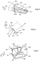
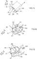
- each front end EV In a first phase, it is possible to start by machining each front end EV having a machining axis parallel to the vertical direction Z and following a third path parallel to the transverse direction Y (arrow F1 'of the figure 7 ), to define the first interface zone ZI1. Then, in a second phase, each front end EV can then be machined by having a machining axis parallel to the longitudinal direction X and by following a second path parallel to the transverse direction Y in the lower part (arrow F2 'of the figure 8 ) to define the second interface zone ZI2. The result of these two machining phases of a front end EV is illustrated on the figure 9 .
- each transverse end ET can then be machined in the lower part of its rear part PR, having a machining axis parallel to the transverse direction Y and following a fourth path, initially parallel to the direction vertical Z (arrow F3 'of the figure 10 ) and then curved with respect to the vertical direction Z (arrow F4 'of the figure 10 ) to remove the tool, to define the fourth interface zone ZI4.
- the result of these two machining phases of a transverse end AND is shown on the figure 11 .
- the first machining phase of each front end EV is carried out with the axis of the tool parallel to the vertical direction Z, as in the prior art, but unlike the latter, the second machining phase with the axis of the tool parallel to the longitudinal direction X, which advantageously makes it possible to dispense with the milling radius of the tool.
- this advantageously makes it possible to advance the longitudinal partition CL of each rear extension PB (in its lower part) forward, in order to better distribute the forces between the upper AS and lower wings AI.
- each transverse end AND is carried out in two phases, unlike the prior art which requires only one.
- the second additional phase is carried out on the transverse partition CT at the level of the two transverse ends ET, in order to allow the passage of each longitudinal partition CL of each rear extension PB (at its front end EV) because it (CL ) is now more advanced than in the prior art.
- each front end EV in at least two phases and each transverse end AND in two phases is possible to machine.
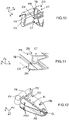
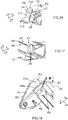
- each front end EV In a first phase, it is possible to start by machining each front end EV having a machining axis parallel to the vertical direction Z and by following a first path initially parallel to the transverse direction Y (arrow F5 'of the figure 12 ), then curved with respect to the transverse direction Y (arrow F6 'of the figure 12 ), and finally again parallel to the transverse direction Y (arrow F7 'of the figure 12 ), to define the first interface zone ZI1. Then, in a second phase, each front end EV can be machined by having a machining axis parallel to the longitudinal direction X and by following a second path parallel to the transverse direction Y (arrow F8 'of the figure 13 ) in the lower part, to define the second interface zone ZI2.
- each front end EV is machined at the level of an internal face of its upper wing AS by having a machining axis parallel to the vertical direction Z and by following a fifth path curved with respect to to the longitudinal direction X (arrow F9 'of the figure 14 ), in order to flatten part of the second interface zone ZI2 at the level of this internal face.
- each transverse end ET it is possible to start by machining each transverse end ET to define in an upper part of its rear part PR a third interface zone ZI3 adapted to the first interface zone ZI1, for docking with a view to welding.
- a machining similar to that described above with reference to the figures 5 and 6 i.e. by means of a tool having a machining axis placed parallel to the vertical direction Z with a path contained in the XY plane, and then having a machining axis placed parallel to the transverse direction Y with a path contained in the XZ plane.
- each transverse end ET can then be machined by having a machining axis parallel to the transverse direction Y and by following a fourth path initially parallel to the longitudinal direction X (arrow F10 'of the figure 16 ), then parallel to the vertical direction Z (arrow F11 'of the figure 16 ), and then curved with respect to the vertical direction (arrow F12 'of the figure 16 ), to define the fourth interface zone ZI4.
- the result of these two machining phases of a transverse end ET is illustrated on the figure 17 .
- the first machining phase of each front end EV is always carried out with the axis of the tool parallel to the vertical direction Z, but with a different trajectory in order to be able to advance even more towards the before each longitudinal partition CL of each rear extension PB (in its lower part).
- the second machining phase is carried out with the axis of the tool parallel to the longitudinal direction X, which advantageously makes it possible to dispense with the milling radius of the tool.
- a third phase can be added to take up the radius machining resulting from the first phase. In the absence of this third phase, to surface the internal face during the first phase, it is necessary to use a smaller tool milling radius and to make several passes, which turns out to be more expensive and more time consuming.
Landscapes
- Engineering & Computer Science (AREA)
- Chemical & Material Sciences (AREA)
- Combustion & Propulsion (AREA)
- Transportation (AREA)
- Mechanical Engineering (AREA)
- Architecture (AREA)
- Structural Engineering (AREA)
- Body Structure For Vehicles (AREA)
- Arc Welding In General (AREA)
- Bending Of Plates, Rods, And Pipes (AREA)
Claims (10)
- Verfahren zur Herstellung eines Aluminiumgestells (BA), das an einem Fahrzeug angebracht werden soll, wobei das Verfahren umfasst i) einen ersten Schritt, bei dem zwei einander gegenüberliegende Querenden (ET) aus einem Querträger (TB) mit einem Trennkreuz (CT) extrudiert in Querrichtung und beide Enden vor (EV) von zwei hinteren Verlängerungen bzw (PB) extrudierten in einer Längsrichtung senkrecht zu der Querrichtung und umfassend jede Trennwand eine Längs (L), verlängert durch obere Flansche (AS) und untere (AI), die mit Löchern versehen sind, die einen Ankerpunkt (PA 3) definieren, in einer vertikalen Richtung, und ii) einen zweiten Schritt, in dem sie die hinteren Teile (PR) bearbeitet von den Querenden (ET) bzw zu den Vorderenden (EV), dadurch gekennzeichnet, dass in dem ersten Schritt bearbeitet wird a) jedes Vorderende (EV) mit einer Bearbeitungsachse parallel zu wobei die vertikale Richtung eine erste Grenzfläche (ZI1) definiert, dann eine Bearbeitungsachse parallel zu der Längsrichtung in einem unteren Teil aufweist, um eine zweite Grenzzone (ZI2) zu definieren, die sich nach hinten erstreckt, die erste Grenzzone (ZI1), und b) jedes Querende (ET) zu definieren, die in einem oberen Teil ihres hinteren Teils (VR) eine dritte Schnittstellenzone (ZI3) angepasst dann an den ersten Schnittstellenbereich (ZI1) eine Bearbeitungsachse aufweist, die parallel zum genannten Querrichtung in einem unteren Teil von sein hinterer Teil (PR) um eine vierte Schnittstellenzone (ZI4) zu definieren, die an die zweite Schnittstellenzone (ZI2) angepasst ist.
- Verfahren nach Anspruch 1, dadurch gekennzeichnet, dass in dem ersten Schritt a) jedes vordere Ende (EV) mit einer Bearbeitungsachse parallel zur vertikalen Richtung und einem ersten Pfad parallel zur Querrichtung bearbeitet wird, um die erste Grenzfläche zu definieren (ZI1), die dann eine Bearbeitungsachse parallel zur Längsrichtung hat und einer zweiten Bahn parallel zur Querrichtung in dem unteren Teil folgt, um die zweite Grenzfläche (ZI2) zu definieren, und b) jedes Querende (ET) mit einem dritten Pfad enthalten ist in einer Ebene senkrecht zu dem vertikalen Richtung und dann in einer Ebene senkrecht enthaltenen Querrichtung zu dem, das in dem unteren Teil seines hinteren Teils (PR), zu definieren, wobei die dritten Schnittstellenzone (ZI3), dann einen Bearbeitungsachse parallelen zu der Querrichtung und folgt einem vierten Pfad, der anfänglich parallel ist in der vertikalen Richtung und dann in Bezug auf die vertikale Richtung in dem unteren Teil seines hinteren Teils (PR) gekrümmt, um die vierte Grenzflächenzone (ZI4) zu definieren.
- Verfahren nach Anspruch 1, dadurch gekennzeichnet, dass in dem ersten Schritt a) jedes vordere Ende (EV) bearbeitet wird, indem eine Bearbeitungsachse parallel zu der vertikalen Richtung und durch Verfolgen einer ersten Bahn, die anfänglich parallel zur Querrichtung ist und dann in Bezug auf gekrümmt ist, bearbeitet wird in die Querrichtung und schließlich wieder parallel zur Querrichtung, um die erste Grenzfläche (ZI1) zu definieren, die dann eine Bearbeitungsachse parallel zur Längsrichtung hat und einer zweiten Bahn parallel zur Querrichtung in dem unteren Teil folgt, um die zweite Grenzfläche (ZI2), und b) jedes Querende (ET) mit einer dritten Bahn, die in einer Ebene senkrecht zu der vertikalen Richtung und dann in einer Ebene senkrecht zur Querrichtung enthalten ist, in dem unteren Teil seines hinteren Teils (PR), dann mit einer Bearbeitungsachse parallel zu besagtem Querrichtung und folgt einem vierten Weg, der anfänglich parallel zu der Längsrichtung, dann parallel zu der vertikalen Richtung ist und dann in Bezug auf die vertikale Richtung gekrümmt ist, um die vierte Grenzfläche (ZI4) zu definieren.
- Verfahren nach Anspruch 3, dadurch gekennzeichnet, dass in dem ersten Schritt nach der Bearbeitung eines Querendes (ET) mit einer Bearbeitungsachse parallel zur Längsrichtung und nach einem zweiten Pfad parallel zur Querrichtung in dem Teilboden zum Definieren des zweiter Schnittstellenbereich (ZI2), wir bearbeiten dieses Querende (ET) an einer Innenfläche des oberen Flügels (AS), um eine Bearbeitungsachse parallel zu dem vertikalen Richtung aufweist, und einen fünften Weg in Bezug gekrümmt folgende Längsrichtung zu dem, um einen Teil der zweiten Grenzfläche (ZI2) auf der Höhe dieser Innenfläche abzuflachen.
- Verfahren nach einem der Ansprüche 1 bis 4, dadurch gekennzeichnet, dass in dem zweiten Schritt, einen Einsatz Verstärkung (PRR) an einer Außenseite Schweiß Unterseite der genannten Längswand (CL) und eine Außenfläche des unteren Flügels (AI) von jedem Heckausschub (PB), in der Nähe seines vorderen Endes (EV).
- Verfahren nach einem der Ansprüche 1 bis 5, dadurch gekennzeichnet, dass im zweiten Schritt auch bearbeitete Vorderteile (PVT) der Querenden (ET) bzw an zwei in besagter Richtung extrudierte vordere Verankerungsteile (PAV) angeschweißt werden mit zwei vertikalen Wänden (PV), die mit Löchern versehen sind, die einen weiteren Verankerungspunkt (PA1) in einer Längsrichtung senkrecht zu der Querrichtung definieren.
- Aluminiumgestell (BA) zur Ausstattung eines Fahrzeugs,
dadurch gekennzeichnet, dass es durch ein Herstellungsverfahren nach einem der vorhergehenden Ansprüche hergestellt wird. - Fahrzeug, dadurch gekennzeichnet, dass es ein Aluminiumgestell (BA) nach Anspruch 7 umfasst.
- Fahrzeug nach Anspruch 8, dadurch gekennzeichnet, dass es zwei Raddreiecke umfasst, von denen jedes einen vorderen Teil umfasst, der an einem der vorderen Verankerungsteile (PAV) des Aluminiumgestells (BA) befestigt ist, und einen hinteren Teil, der an einer der hinteren Verlängerungen befestigt ist (PB) des Aluminiumgestells (BA).
- Fahrzeug nach Anspruch 8 oder 9, dadurch gekennzeichnet, dass es vom Automobiltyp ist.
Applications Claiming Priority (2)
| Application Number | Priority Date | Filing Date | Title |
|---|---|---|---|
| FR1757517A FR3069833B1 (fr) | 2017-08-04 | 2017-08-04 | Procede de realisation d’un berceau en aluminium a efforts repartis sur les ailes de prolonges arriere, pour un vehicule |
| PCT/FR2018/051627 WO2019025679A1 (fr) | 2017-08-04 | 2018-07-02 | Procédé de réalisation d'un berceau en aluminium à efforts répartis sur les ailes de prolonges arrière, pour un véhicule |
Publications (2)
| Publication Number | Publication Date |
|---|---|
| EP3661835A1 EP3661835A1 (de) | 2020-06-10 |
| EP3661835B1 true EP3661835B1 (de) | 2021-08-25 |
Family
ID=59974667
Family Applications (1)
| Application Number | Title | Priority Date | Filing Date |
|---|---|---|---|
| EP18752546.4A Active EP3661835B1 (de) | 2017-08-04 | 2018-07-02 | Verfahren zur herstellung einer aufnahme aus aluminium mit lastenverteilung über die flügel der rückverlängerungen für ein fahrzeug |
Country Status (5)
| Country | Link |
|---|---|
| EP (1) | EP3661835B1 (de) |
| CN (1) | CN110997462B (de) |
| FR (1) | FR3069833B1 (de) |
| MA (1) | MA49745B1 (de) |
| WO (1) | WO2019025679A1 (de) |
Family Cites Families (9)
| Publication number | Priority date | Publication date | Assignee | Title |
|---|---|---|---|---|
| DE19802806C2 (de) * | 1998-01-27 | 2003-09-18 | Daimler Chrysler Ag | Integralträger zur Aufnahme von Funktionsaggregaten eines Kraftfahrzeugs |
| JP4247902B2 (ja) * | 2004-03-31 | 2009-04-02 | 本田技研工業株式会社 | ブッシュ取付構造 |
| DE102009040821B3 (de) * | 2009-09-10 | 2011-06-09 | Thyssenkrupp Presta Ag | Vorderachsträger mit integriertem Lenkungsgehäuse |
| CN102320330B (zh) * | 2011-07-06 | 2013-02-13 | 隆鑫通用动力股份有限公司 | 工程车及其车架总成 |
| FR2989055B1 (fr) * | 2012-04-04 | 2014-04-25 | Peugeot Citroen Automobiles Sa | Cloison de pied milieu affaiblie en y et renforcee en z. |
| FR3006278B1 (fr) * | 2013-05-31 | 2016-12-02 | Peugeot Citroen Automobiles Sa | Berceau pour train roulant de vehicule automobile |
| DE102014111794A1 (de) * | 2014-08-19 | 2016-02-25 | Dr. Ing. H.C. F. Porsche Aktiengesellschaft | Versteifungsanordnung für einen Vorderwagen eines Kraftfahrzeugs |
| FR3037305B1 (fr) * | 2015-06-12 | 2017-07-07 | Peugeot Citroen Automobiles Sa | Dispositif d'ancrage multipieces pour une traverse de berceau en aluminium de vehicule automobile |
| FR3046590A1 (fr) * | 2016-01-11 | 2017-07-14 | Peugeot Citroen Automobiles Sa | Berceau avant de vehicule |
-
2017
- 2017-08-04 FR FR1757517A patent/FR3069833B1/fr not_active Expired - Fee Related
-
2018
- 2018-07-02 EP EP18752546.4A patent/EP3661835B1/de active Active
- 2018-07-02 CN CN201880050857.0A patent/CN110997462B/zh active Active
- 2018-07-02 WO PCT/FR2018/051627 patent/WO2019025679A1/fr not_active Ceased
- 2018-07-02 MA MA49745A patent/MA49745B1/fr unknown
Also Published As
| Publication number | Publication date |
|---|---|
| CN110997462B (zh) | 2022-04-15 |
| MA49745B1 (fr) | 2021-09-30 |
| EP3661835A1 (de) | 2020-06-10 |
| CN110997462A (zh) | 2020-04-10 |
| FR3069833A1 (fr) | 2019-02-08 |
| MA49745A (fr) | 2021-04-14 |
| WO2019025679A1 (fr) | 2019-02-07 |
| FR3069833B1 (fr) | 2019-08-09 |
Similar Documents
| Publication | Publication Date | Title |
|---|---|---|
| EP3661835B1 (de) | Verfahren zur herstellung einer aufnahme aus aluminium mit lastenverteilung über die flügel der rückverlängerungen für ein fahrzeug | |
| EP3204282A1 (de) | Fersenplatte mit einem strukturierungseinsatz | |
| FR3037305A1 (fr) | Dispositif d'ancrage multipieces pour une traverse de berceau en aluminium de vehicule automobile | |
| EP3428044B1 (de) | Aluminiumträger mit führungsmitteln des radträgers für ein fahrzeug | |
| EP1702832B1 (de) | Längsträger und Struktur eines Kraftfahrzeuges mit so einem Längsträger | |
| FR3099741A1 (fr) | Déflecteur arrière à extension longitudinale de guidage, pour un soubassement de véhicule | |
| FR3148207A1 (fr) | Pièce d’implication de véhicule automobile, pour l’implication d’un longeron latéral dans un choc par l’avant | |
| FR3050427A1 (fr) | Berceau de vehicule a traverse reduite et pieces de renfort | |
| FR3135234A1 (fr) | Peau de pare-chocs à déformations latérales contrôlées, pour un véhicule terrestre | |
| FR3141431A1 (fr) | Pièce de renfort à encaissement d’efforts transversaux, pour une prolonge de berceau d’une structure de véhicule automobile | |
| EP4646358A1 (de) | Verstärkungsteil für einen kraftfahrzeugunterboden | |
| EP3823881B1 (de) | Seitenschienenwände zur biegebelastung bei einem seitenaufprall | |
| FR3161191A1 (fr) | Pièce de renfort pour répartir un effort subi par un longeron de véhicule automobile lors d’un choc par l’avant | |
| FR2900896A1 (fr) | Element de liaison pour realiser un longeron, longeron comportant un tel element et vehicule automobile comportant au moins un tel longeron | |
| FR3140056A1 (fr) | Pièce de renfort pour une pièce d’appui de façade de véhicule automobile | |
| EP3956178B1 (de) | Anti-rotation-verkleidung für eine säule eines kraftfahrzeugs | |
| FR2991940A1 (fr) | Structure de vehicule avec longeron renforce. | |
| WO2023073295A1 (fr) | Véhicule automobile avec traverse d'assise sur batteries de traction | |
| FR3148981A1 (fr) | Pièce de renfort anti-translation pour protéger un tablier de véhicule automobile lors d’un choc par l’avant | |
| EP4448373A1 (de) | Landfahrzeugstruktur mit verstärkungsteilen zur übertragung einer querkraft | |
| EP4351952A1 (de) | Fahrzeug mit einer struktur mit teilen zur verstärkung von säulen | |
| EP4511275A1 (de) | Heckschale mit erhöhter festigkeit für ein landfahrzeug | |
| FR3122854A1 (fr) | Dispositif d’absorption à absorbeurs d’énergie à direction de compression prédéfinie, pour un véhicule terrestre | |
| WO2024033580A1 (fr) | Traverse arrière de véhicule terrestre, adaptée à différentes motorisations | |
| FR3148412A1 (fr) | Pièce de renfort pour protéger un tablier de véhicule automobile lors d’un choc par l’avant |
Legal Events
| Date | Code | Title | Description |
|---|---|---|---|
| STAA | Information on the status of an ep patent application or granted ep patent |
Free format text: STATUS: UNKNOWN |
|
| STAA | Information on the status of an ep patent application or granted ep patent |
Free format text: STATUS: THE INTERNATIONAL PUBLICATION HAS BEEN MADE |
|
| PUAI | Public reference made under article 153(3) epc to a published international application that has entered the european phase |
Free format text: ORIGINAL CODE: 0009012 |
|
| STAA | Information on the status of an ep patent application or granted ep patent |
Free format text: STATUS: REQUEST FOR EXAMINATION WAS MADE |
|
| 17P | Request for examination filed |
Effective date: 20200115 |
|
| AK | Designated contracting states |
Kind code of ref document: A1 Designated state(s): AL AT BE BG CH CY CZ DE DK EE ES FI FR GB GR HR HU IE IS IT LI LT LU LV MC MK MT NL NO PL PT RO RS SE SI SK SM TR |
|
| AX | Request for extension of the european patent |
Extension state: BA ME |
|
| DAX | Request for extension of the european patent (deleted) | ||
| RAP1 | Party data changed (applicant data changed or rights of an application transferred) |
Owner name: PSA AUTOMOBILES SA |
|
| RAV | Requested validation state of the european patent: fee paid |
Extension state: MA Effective date: 20200115 |
|
| GRAP | Despatch of communication of intention to grant a patent |
Free format text: ORIGINAL CODE: EPIDOSNIGR1 |
|
| STAA | Information on the status of an ep patent application or granted ep patent |
Free format text: STATUS: GRANT OF PATENT IS INTENDED |
|
| INTG | Intention to grant announced |
Effective date: 20210316 |
|
| GRAS | Grant fee paid |
Free format text: ORIGINAL CODE: EPIDOSNIGR3 |
|
| GRAA | (expected) grant |
Free format text: ORIGINAL CODE: 0009210 |
|
| STAA | Information on the status of an ep patent application or granted ep patent |
Free format text: STATUS: THE PATENT HAS BEEN GRANTED |
|
| AK | Designated contracting states |
Kind code of ref document: B1 Designated state(s): AL AT BE BG CH CY CZ DE DK EE ES FI FR GB GR HR HU IE IS IT LI LT LU LV MC MK MT NL NO PL PT RO RS SE SI SK SM TR |
|
| REG | Reference to a national code |
Ref country code: CH Ref legal event code: EP |
|
| REG | Reference to a national code |
Ref country code: DE Ref legal event code: R096 Ref document number: 602018022469 Country of ref document: DE Ref country code: DE Ref legal event code: R084 Ref document number: 602018022469 Country of ref document: DE |
|
| REG | Reference to a national code |
Ref country code: IE Ref legal event code: FG4D Free format text: LANGUAGE OF EP DOCUMENT: FRENCH Ref country code: AT Ref legal event code: REF Ref document number: 1423532 Country of ref document: AT Kind code of ref document: T Effective date: 20210915 |
|
| REG | Reference to a national code |
Ref country code: MA Ref legal event code: VAGR Ref document number: 49745 Country of ref document: MA Kind code of ref document: B1 |
|
| REG | Reference to a national code |
Ref country code: GB Ref legal event code: 746 Effective date: 20211101 |
|
| REG | Reference to a national code |
Ref country code: LT Ref legal event code: MG9D |
|
| REG | Reference to a national code |
Ref country code: NL Ref legal event code: MP Effective date: 20210825 |
|
| REG | Reference to a national code |
Ref country code: AT Ref legal event code: MK05 Ref document number: 1423532 Country of ref document: AT Kind code of ref document: T Effective date: 20210825 |
|
| PG25 | Lapsed in a contracting state [announced via postgrant information from national office to epo] |
Ref country code: BG Free format text: LAPSE BECAUSE OF FAILURE TO SUBMIT A TRANSLATION OF THE DESCRIPTION OR TO PAY THE FEE WITHIN THE PRESCRIBED TIME-LIMIT Effective date: 20211125 Ref country code: AT Free format text: LAPSE BECAUSE OF FAILURE TO SUBMIT A TRANSLATION OF THE DESCRIPTION OR TO PAY THE FEE WITHIN THE PRESCRIBED TIME-LIMIT Effective date: 20210825 Ref country code: LT Free format text: LAPSE BECAUSE OF FAILURE TO SUBMIT A TRANSLATION OF THE DESCRIPTION OR TO PAY THE FEE WITHIN THE PRESCRIBED TIME-LIMIT Effective date: 20210825 Ref country code: NO Free format text: LAPSE BECAUSE OF FAILURE TO SUBMIT A TRANSLATION OF THE DESCRIPTION OR TO PAY THE FEE WITHIN THE PRESCRIBED TIME-LIMIT Effective date: 20211125 Ref country code: PT Free format text: LAPSE BECAUSE OF FAILURE TO SUBMIT A TRANSLATION OF THE DESCRIPTION OR TO PAY THE FEE WITHIN THE PRESCRIBED TIME-LIMIT Effective date: 20211227 Ref country code: RS Free format text: LAPSE BECAUSE OF FAILURE TO SUBMIT A TRANSLATION OF THE DESCRIPTION OR TO PAY THE FEE WITHIN THE PRESCRIBED TIME-LIMIT Effective date: 20210825 Ref country code: SE Free format text: LAPSE BECAUSE OF FAILURE TO SUBMIT A TRANSLATION OF THE DESCRIPTION OR TO PAY THE FEE WITHIN THE PRESCRIBED TIME-LIMIT Effective date: 20210825 Ref country code: HR Free format text: LAPSE BECAUSE OF FAILURE TO SUBMIT A TRANSLATION OF THE DESCRIPTION OR TO PAY THE FEE WITHIN THE PRESCRIBED TIME-LIMIT Effective date: 20210825 Ref country code: FI Free format text: LAPSE BECAUSE OF FAILURE TO SUBMIT A TRANSLATION OF THE DESCRIPTION OR TO PAY THE FEE WITHIN THE PRESCRIBED TIME-LIMIT Effective date: 20210825 Ref country code: ES Free format text: LAPSE BECAUSE OF FAILURE TO SUBMIT A TRANSLATION OF THE DESCRIPTION OR TO PAY THE FEE WITHIN THE PRESCRIBED TIME-LIMIT Effective date: 20210825 |
|
| PG25 | Lapsed in a contracting state [announced via postgrant information from national office to epo] |
Ref country code: PL Free format text: LAPSE BECAUSE OF FAILURE TO SUBMIT A TRANSLATION OF THE DESCRIPTION OR TO PAY THE FEE WITHIN THE PRESCRIBED TIME-LIMIT Effective date: 20210825 Ref country code: LV Free format text: LAPSE BECAUSE OF FAILURE TO SUBMIT A TRANSLATION OF THE DESCRIPTION OR TO PAY THE FEE WITHIN THE PRESCRIBED TIME-LIMIT Effective date: 20210825 Ref country code: GR Free format text: LAPSE BECAUSE OF FAILURE TO SUBMIT A TRANSLATION OF THE DESCRIPTION OR TO PAY THE FEE WITHIN THE PRESCRIBED TIME-LIMIT Effective date: 20211126 |
|
| PG25 | Lapsed in a contracting state [announced via postgrant information from national office to epo] |
Ref country code: NL Free format text: LAPSE BECAUSE OF FAILURE TO SUBMIT A TRANSLATION OF THE DESCRIPTION OR TO PAY THE FEE WITHIN THE PRESCRIBED TIME-LIMIT Effective date: 20210825 |
|
| PG25 | Lapsed in a contracting state [announced via postgrant information from national office to epo] |
Ref country code: DK Free format text: LAPSE BECAUSE OF FAILURE TO SUBMIT A TRANSLATION OF THE DESCRIPTION OR TO PAY THE FEE WITHIN THE PRESCRIBED TIME-LIMIT Effective date: 20210825 |
|
| REG | Reference to a national code |
Ref country code: DE Ref legal event code: R097 Ref document number: 602018022469 Country of ref document: DE |
|
| PG25 | Lapsed in a contracting state [announced via postgrant information from national office to epo] |
Ref country code: SM Free format text: LAPSE BECAUSE OF FAILURE TO SUBMIT A TRANSLATION OF THE DESCRIPTION OR TO PAY THE FEE WITHIN THE PRESCRIBED TIME-LIMIT Effective date: 20210825 Ref country code: SK Free format text: LAPSE BECAUSE OF FAILURE TO SUBMIT A TRANSLATION OF THE DESCRIPTION OR TO PAY THE FEE WITHIN THE PRESCRIBED TIME-LIMIT Effective date: 20210825 Ref country code: RO Free format text: LAPSE BECAUSE OF FAILURE TO SUBMIT A TRANSLATION OF THE DESCRIPTION OR TO PAY THE FEE WITHIN THE PRESCRIBED TIME-LIMIT Effective date: 20210825 Ref country code: EE Free format text: LAPSE BECAUSE OF FAILURE TO SUBMIT A TRANSLATION OF THE DESCRIPTION OR TO PAY THE FEE WITHIN THE PRESCRIBED TIME-LIMIT Effective date: 20210825 Ref country code: CZ Free format text: LAPSE BECAUSE OF FAILURE TO SUBMIT A TRANSLATION OF THE DESCRIPTION OR TO PAY THE FEE WITHIN THE PRESCRIBED TIME-LIMIT Effective date: 20210825 Ref country code: AL Free format text: LAPSE BECAUSE OF FAILURE TO SUBMIT A TRANSLATION OF THE DESCRIPTION OR TO PAY THE FEE WITHIN THE PRESCRIBED TIME-LIMIT Effective date: 20210825 |
|
| PLBE | No opposition filed within time limit |
Free format text: ORIGINAL CODE: 0009261 |
|
| STAA | Information on the status of an ep patent application or granted ep patent |
Free format text: STATUS: NO OPPOSITION FILED WITHIN TIME LIMIT |
|
| 26N | No opposition filed |
Effective date: 20220527 |
|
| PG25 | Lapsed in a contracting state [announced via postgrant information from national office to epo] |
Ref country code: SI Free format text: LAPSE BECAUSE OF FAILURE TO SUBMIT A TRANSLATION OF THE DESCRIPTION OR TO PAY THE FEE WITHIN THE PRESCRIBED TIME-LIMIT Effective date: 20210825 |
|
| PG25 | Lapsed in a contracting state [announced via postgrant information from national office to epo] |
Ref country code: MC Free format text: LAPSE BECAUSE OF FAILURE TO SUBMIT A TRANSLATION OF THE DESCRIPTION OR TO PAY THE FEE WITHIN THE PRESCRIBED TIME-LIMIT Effective date: 20210825 |
|
| REG | Reference to a national code |
Ref country code: CH Ref legal event code: PL |
|
| REG | Reference to a national code |
Ref country code: BE Ref legal event code: MM Effective date: 20220731 |
|
| PG25 | Lapsed in a contracting state [announced via postgrant information from national office to epo] |
Ref country code: LU Free format text: LAPSE BECAUSE OF NON-PAYMENT OF DUE FEES Effective date: 20220702 Ref country code: LI Free format text: LAPSE BECAUSE OF NON-PAYMENT OF DUE FEES Effective date: 20220731 Ref country code: CH Free format text: LAPSE BECAUSE OF NON-PAYMENT OF DUE FEES Effective date: 20220731 |
|
| PG25 | Lapsed in a contracting state [announced via postgrant information from national office to epo] |
Ref country code: BE Free format text: LAPSE BECAUSE OF NON-PAYMENT OF DUE FEES Effective date: 20220731 |
|
| PG25 | Lapsed in a contracting state [announced via postgrant information from national office to epo] |
Ref country code: IE Free format text: LAPSE BECAUSE OF NON-PAYMENT OF DUE FEES Effective date: 20220702 |
|
| REG | Reference to a national code |
Ref country code: DE Ref legal event code: R081 Ref document number: 602018022469 Country of ref document: DE Owner name: STELLANTIS AUTO SAS, FR Free format text: FORMER OWNER: PSA AUTOMOBILES SA, POISSY, FR |
|
| PG25 | Lapsed in a contracting state [announced via postgrant information from national office to epo] |
Ref country code: MK Free format text: LAPSE BECAUSE OF FAILURE TO SUBMIT A TRANSLATION OF THE DESCRIPTION OR TO PAY THE FEE WITHIN THE PRESCRIBED TIME-LIMIT Effective date: 20210825 Ref country code: CY Free format text: LAPSE BECAUSE OF FAILURE TO SUBMIT A TRANSLATION OF THE DESCRIPTION OR TO PAY THE FEE WITHIN THE PRESCRIBED TIME-LIMIT Effective date: 20210825 |
|
| PG25 | Lapsed in a contracting state [announced via postgrant information from national office to epo] |
Ref country code: HU Free format text: LAPSE BECAUSE OF FAILURE TO SUBMIT A TRANSLATION OF THE DESCRIPTION OR TO PAY THE FEE WITHIN THE PRESCRIBED TIME-LIMIT; INVALID AB INITIO Effective date: 20180702 |
|
| PG25 | Lapsed in a contracting state [announced via postgrant information from national office to epo] |
Ref country code: MT Free format text: LAPSE BECAUSE OF FAILURE TO SUBMIT A TRANSLATION OF THE DESCRIPTION OR TO PAY THE FEE WITHIN THE PRESCRIBED TIME-LIMIT Effective date: 20210825 |
|
| PGFP | Annual fee paid to national office [announced via postgrant information from national office to epo] |
Ref country code: GB Payment date: 20250619 Year of fee payment: 8 |
|
| PGFP | Annual fee paid to national office [announced via postgrant information from national office to epo] |
Ref country code: FR Payment date: 20250620 Year of fee payment: 8 |
|
| PGFP | Annual fee paid to national office [announced via postgrant information from national office to epo] |
Ref country code: DE Payment date: 20250620 Year of fee payment: 8 |
|
| PGFP | Annual fee paid to national office [announced via postgrant information from national office to epo] |
Ref country code: IT Payment date: 20250619 Year of fee payment: 8 |
|
| VSFP | Annual fee paid to validation state [announced via postgrant information from national office to epo] |
Ref country code: MA Payment date: 20230628 Year of fee payment: 6 |
|
| VSFP | Annual fee paid to validation state [announced via postgrant information from national office to epo] |
Ref country code: MA Payment date: 20220712 Year of fee payment: 5 |
|
| VSFP | Annual fee paid to validation state [announced via postgrant information from national office to epo] |
Ref country code: MA Payment date: 20240703 Year of fee payment: 7 |
|
| VSFP | Annual fee paid to validation state [announced via postgrant information from national office to epo] |
Ref country code: MA Payment date: 20250708 Year of fee payment: 8 |
|
| PG25 | Lapsed in a contracting state [announced via postgrant information from national office to epo] |
Ref country code: TR Free format text: LAPSE BECAUSE OF FAILURE TO SUBMIT A TRANSLATION OF THE DESCRIPTION OR TO PAY THE FEE WITHIN THE PRESCRIBED TIME-LIMIT Effective date: 20210825 |