EP3662200B1 - Appareil d'éclairage et de délimitation de route - Google Patents
Appareil d'éclairage et de délimitation de route Download PDFInfo
- Publication number
- EP3662200B1 EP3662200B1 EP18760035.8A EP18760035A EP3662200B1 EP 3662200 B1 EP3662200 B1 EP 3662200B1 EP 18760035 A EP18760035 A EP 18760035A EP 3662200 B1 EP3662200 B1 EP 3662200B1
- Authority
- EP
- European Patent Office
- Prior art keywords
- road lighting
- delineating
- road
- leds
- lighting
- Prior art date
- Legal status (The legal status is an assumption and is not a legal conclusion. Google has not performed a legal analysis and makes no representation as to the accuracy of the status listed.)
- Active
Links
Images

Classifications
-
- F—MECHANICAL ENGINEERING; LIGHTING; HEATING; WEAPONS; BLASTING
- F21—LIGHTING
- F21S—NON-PORTABLE LIGHTING DEVICES; SYSTEMS THEREOF; VEHICLE LIGHTING DEVICES SPECIALLY ADAPTED FOR VEHICLE EXTERIORS
- F21S8/00—Lighting devices intended for fixed installation
- F21S8/08—Lighting devices intended for fixed installation with a standard
- F21S8/085—Lighting devices intended for fixed installation with a standard of high-built type, e.g. street light
- F21S8/086—Lighting devices intended for fixed installation with a standard of high-built type, e.g. street light with lighting device attached sideways of the standard, e.g. for roads and highways
-
- E—FIXED CONSTRUCTIONS
- E01—CONSTRUCTION OF ROADS, RAILWAYS, OR BRIDGES
- E01F—ADDITIONAL WORK, SUCH AS EQUIPPING ROADS OR THE CONSTRUCTION OF PLATFORMS, HELICOPTER LANDING STAGES, SIGNS, SNOW FENCES, OR THE LIKE
- E01F9/00—Arrangement of road signs or traffic signals; Arrangements for enforcing caution
- E01F9/60—Upright bodies, e.g. marker posts or bollards; Supports for road signs
- E01F9/604—Upright bodies, e.g. marker posts or bollards; Supports for road signs specially adapted for particular signalling purposes, e.g. for indicating curves, road works or pedestrian crossings
- E01F9/615—Upright bodies, e.g. marker posts or bollards; Supports for road signs specially adapted for particular signalling purposes, e.g. for indicating curves, road works or pedestrian crossings illuminated
-
- E—FIXED CONSTRUCTIONS
- E01—CONSTRUCTION OF ROADS, RAILWAYS, OR BRIDGES
- E01F—ADDITIONAL WORK, SUCH AS EQUIPPING ROADS OR THE CONSTRUCTION OF PLATFORMS, HELICOPTER LANDING STAGES, SIGNS, SNOW FENCES, OR THE LIKE
- E01F9/00—Arrangement of road signs or traffic signals; Arrangements for enforcing caution
- E01F9/60—Upright bodies, e.g. marker posts or bollards; Supports for road signs
- E01F9/658—Upright bodies, e.g. marker posts or bollards; Supports for road signs characterised by means for fixing
- E01F9/669—Upright bodies, e.g. marker posts or bollards; Supports for road signs characterised by means for fixing for fastening to safety barriers or the like
-
- F—MECHANICAL ENGINEERING; LIGHTING; HEATING; WEAPONS; BLASTING
- F21—LIGHTING
- F21V—FUNCTIONAL FEATURES OR DETAILS OF LIGHTING DEVICES OR SYSTEMS THEREOF; STRUCTURAL COMBINATIONS OF LIGHTING DEVICES WITH OTHER ARTICLES, NOT OTHERWISE PROVIDED FOR
- F21V13/00—Producing particular characteristics or distribution of the light emitted by means of a combination of elements specified in two or more of main groups F21V1/00 - F21V11/00
- F21V13/02—Combinations of only two kinds of elements
- F21V13/04—Combinations of only two kinds of elements the elements being reflectors and refractors
-
- F—MECHANICAL ENGINEERING; LIGHTING; HEATING; WEAPONS; BLASTING
- F21—LIGHTING
- F21V—FUNCTIONAL FEATURES OR DETAILS OF LIGHTING DEVICES OR SYSTEMS THEREOF; STRUCTURAL COMBINATIONS OF LIGHTING DEVICES WITH OTHER ARTICLES, NOT OTHERWISE PROVIDED FOR
- F21V19/00—Fastening of light sources or lamp holders
- F21V19/001—Fastening of light sources or lamp holders the light sources being semiconductors devices, e.g. LEDs
- F21V19/003—Fastening of light source holders, e.g. of circuit boards or substrates holding light sources
- F21V19/0045—Fastening of light source holders, e.g. of circuit boards or substrates holding light sources by tongue and groove connections, e.g. dovetail interlocking means fixed by sliding
-
- F—MECHANICAL ENGINEERING; LIGHTING; HEATING; WEAPONS; BLASTING
- F21—LIGHTING
- F21V—FUNCTIONAL FEATURES OR DETAILS OF LIGHTING DEVICES OR SYSTEMS THEREOF; STRUCTURAL COMBINATIONS OF LIGHTING DEVICES WITH OTHER ARTICLES, NOT OTHERWISE PROVIDED FOR
- F21V5/00—Refractors for light sources
- F21V5/04—Refractors for light sources of lens shape
-
- F—MECHANICAL ENGINEERING; LIGHTING; HEATING; WEAPONS; BLASTING
- F21—LIGHTING
- F21V—FUNCTIONAL FEATURES OR DETAILS OF LIGHTING DEVICES OR SYSTEMS THEREOF; STRUCTURAL COMBINATIONS OF LIGHTING DEVICES WITH OTHER ARTICLES, NOT OTHERWISE PROVIDED FOR
- F21V7/00—Reflectors for light sources
- F21V7/04—Optical design
- F21V7/06—Optical design with parabolic curvature
-
- F—MECHANICAL ENGINEERING; LIGHTING; HEATING; WEAPONS; BLASTING
- F21—LIGHTING
- F21W—INDEXING SCHEME ASSOCIATED WITH SUBCLASSES F21K, F21L, F21S and F21V, RELATING TO USES OR APPLICATIONS OF LIGHTING DEVICES OR SYSTEMS
- F21W2131/00—Use or application of lighting devices or systems not provided for in codes F21W2102/00-F21W2121/00
- F21W2131/10—Outdoor lighting
- F21W2131/103—Outdoor lighting of streets or roads
-
- F—MECHANICAL ENGINEERING; LIGHTING; HEATING; WEAPONS; BLASTING
- F21—LIGHTING
- F21Y—INDEXING SCHEME ASSOCIATED WITH SUBCLASSES F21K, F21L, F21S and F21V, RELATING TO THE FORM OR THE KIND OF THE LIGHT SOURCES OR OF THE COLOUR OF THE LIGHT EMITTED
- F21Y2103/00—Elongate light sources, e.g. fluorescent tubes
- F21Y2103/10—Elongate light sources, e.g. fluorescent tubes comprising a linear array of point-like light-generating elements
-
- F—MECHANICAL ENGINEERING; LIGHTING; HEATING; WEAPONS; BLASTING
- F21—LIGHTING
- F21Y—INDEXING SCHEME ASSOCIATED WITH SUBCLASSES F21K, F21L, F21S and F21V, RELATING TO THE FORM OR THE KIND OF THE LIGHT SOURCES OR OF THE COLOUR OF THE LIGHT EMITTED
- F21Y2115/00—Light-generating elements of semiconductor light sources
- F21Y2115/10—Light-emitting diodes [LED]
Definitions
- This invention refers to devices and apparatuses for illuminating outdoor areas intended to the vehicle circulation, like roads and expressways, and more specifically concerns a road lighting and delineating apparatus in conformity with the principles and criteria outlined in the Italian regulations of the sector, defined by the UNI 11248 "Road lighting" standard.
- the outdoor lighting apparatus known and widely used for road lighting, like lampposts, street light towers, street lights, generally include a supporting pole or bracket, with one end fixed to the ground or to an adjacent construction and the other end destined to sustain a housing for a light source selected, for example, among incandescent light bulbs, high-pressure mercury vapor light bulbs, high- or low- pressure sodium vapor lamps, LED lamps.
- a light source selected, for example, among incandescent light bulbs, high-pressure mercury vapor light bulbs, high- or low- pressure sodium vapor lamps, LED lamps.
- the poles must be tall enough to position the light source at a height sufficiently elevated to allow the uniform illumination of the roadway, in total compliance with all legal requirements, and with a section diameter that grants sturdiness and stability to the entire lighting apparatus. More in detail, the law requires that the poles have variable heights according to the type of use, for example heights comprised between 8 and 12 meters for road and expressway lighting, so that the driver of a vehicle has optimal perception of both the roadway layout and the stopping distance from a potential obstacle present along the traveling lane or on the carriageway.
- poles are made mainly of steel.
- fiberglass makes it possible to obtain very lightweight poles that are easily handled, but having larger section diameters and therefore requiring very bulky supports, while the use of aluminum ensures a better guarantee of durability over time and is easier to work with, consequently this material can take on a wide variety of shapes, which is very popular in urban settings, but also implies higher production costs.
- the light source positioned at a considerable height makes the maintenance thereof complex and in some cases dangerous. Indeed, when there is a breakdown or a malfunction of the lighting, a maintenance technician must reach the light source by climbing up the relative supporting pole or using a lift truck, thereby exposing himself to all the dangers that the option selected implies. Moreover, if ever the light source should detach from the supporting pole, for example in an area subject to strong gusts of wind, there is a very serious risk that it strikes either a vehicle or a person with a force directly proportional to its fall.
- the higher the position of the light source the greater the probability that, in the presence of rain or fog, one or more dark zones or the so-called veiling luminance may appear on the asphalt, respectively. It is indeed known that the rain settled on the asphalt gives rise to zones that appear black to an observer, in particular where the lighting apparatus, the eye of the observer and the roadway are aligned (i.e. at the critical angle or angle of Brewster), due to the fact that the light is reflected by the road surface outside of the observer's own field of view.
- WO 2015/062863 discloses a lighting device for roads comprising a reflector provided with an elliptical shaped light emission window.
- the reflector further comprises a cavity surrounded by light reflecting walls which extend between a light emission window and a light source, such as a LED type source.
- the window is provided with an optical plate having an outcoupling structure facing towards the light source and realized by a plurality of prisms suitable alternatively for refracting and reflecting the light.
- An object of the present invention is to improve the known lighting apparatus for illuminating and delineating outdoor areas, like streets and expressways, intended for vehicle traffic, in particular to realize a road lighting and delineating apparatus that is in conformity with the regulations of the sector, free from the drawbacks described above and at the same time simple and economical to construct.
- Another object is to provide a road lighting and delineating apparatus with moderate dimensions, with no supporting pole or bracket and suitable to be installed on essentially vertical surfaces like, for example, a tunnel wall, the surface of a Jersey barrier, or the band of a guardrail.
- Yet another object is to realize a road lighting and delineating apparatus that improves visual comfort, and hence traffic safety, and supports the orientation of the driver under any weather conditions and, in particular, in the presence of rain and/or fog.
- Another further object is obtain a road lighting and delineating apparatus that does not constitute an obstacle in case of impact by a vehicle, thereby minimizing the consequences for both the driver and the passengers of the vehicle in question.
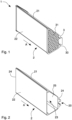
- the figures illustrate a road lighting and delineating apparatus 1 according to the present invention, which can be installed on a supporting structure 10 at a set installation height H from a road surface S, which includes a central body 2 with a molded part 21 and a frontal wall 22 that is substantially transparent.
- the central body 2 has an elongated shape, more specifically the shape of a rectangular parallelepiped with a trapezoidal section, extends in a longitudinal direction A and is provided with a cavity 23 with an opening 25 on at least one of two sides 24 opposed to each another and transversal to said longitudinal direction A.
- the molded portion 21 and the frontal wall 22 may be in a single body or the central body 2 may form a monolithic element.
- the molded portion 21 and the frontal wall 22 can be separated and destined to be coupled to form the central body 2 with the cavity 23.
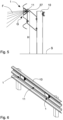
- the molded portion 21 of the central body 2 is equipped with an external seat 20, that in the embodiments illustrated in the figures is opposite the frontal wall 22, and can be engaged with a fixing element 27, comprising for example a bracket intended to be fixed in an adjustable and reversible way to the supporting structure 10, such as the wall of a tunnel, a surface of a Jersey barrier, a band of a guardrail, as in the example illustrated.
- a fixing element 27 comprising for example a bracket intended to be fixed in an adjustable and reversible way to the supporting structure 10, such as the wall of a tunnel, a surface of a Jersey barrier, a band of a guardrail, as in the example illustrated.
- the bracket 27 can be fixed by using a suitable bolt in a slot present on the lower curve of the band of the guardrail 10 as illustrated in Figures 5 and 6 , or by means of a suitable clamp when the bracket has the same shape as the profile of the guardrail 10 itself.
- the central body 2 can be housed in this latter in a compact assembly configuration G that is particularly advantageous, in which the volume of the apparatus 1 is notably reduced, in particular without protruding from the guardrail itself.
- the bracket 27 can be fixed in an adjustable way to the supporting structure 10, in a way known by a person skilled in the field and not further explained here in detail, in such a way as to be able to suitable orient the apparatus 1, in particular inclining it on a vertical plane of an angle, for example of 15°, according to said installation height H from the road surface S. Consequently, the apparatus 1 can be positioned at a set installation height H according to particular road conformations, like curved stretches that require specific attention in controlling the lighting, especially at an installation height H less than 150 cm, for instance equal to 80 cm.
- the road lighting and delineating apparatus 1 includes at least one blind plug 3 with an operational surface 30, designed to be reversibly coupled with the central body 2 at said opening 25 so as to close, preferably hermetically, the cavity 23.
- the central body 2 is provided with a plurality of threaded holes while the blind plug 3 is provided with a corresponding plurality of through holes; in this way the coupling can be simply carried out by means of screws that pass through the holes of the blind plug 3 and screw into the threaded holes of the central body 2.
- the blind plug 3 can be coupled with the central body 2 by interlocking or using magnetic coupling devices.
- a road delineating system for example a passive signaling system namely a reflector or retroreflector 31 to signal the presence of an obstacle as represented by the supporting structure 10 to which the apparatus 1 is fixed or the apparatus 1 itself.
- the operational surface 30 can house an active road delineating system, as depicted in the second embodiment illustrated in Figure 3 , for example, a module or board 32 with a plurality of further LEDs 33 to delineate exits, curves, dangerous stretches, rotaries, intersections, to support the orientation of a driver in case of fog and warn him promptly of the presence of accidents or roadway construction sites.
- a lighting system 4 is housed inside the cavity 23 and comprises at least one LED 41 adapted to emit light rays L, to which a refractive lens 43 and a reflective optical system 44 are associated.
- the LED 41 is mounted on a respective printed circuit 47 which is slidably coupled to the supporting means 42 positioned inside the cavity 23 and connected to the central body 2, for example to a rear wall 26 of the molded portion 21 opposite the frontal wall 22.
- the printed circuit 47 that is the LED 41, sliding along the supporting means 42 can be stably positioned in a suitable position inside the cavity 23.
- the supporting means 42 are also conveniently constructed in thermally conductive material, for example in aluminum, so as to act also as a heat sink for the printed circuit 47.
- the printed circuit 47 is equipped with a length of cable, not shown in the figure, that comes out of the apparatus 1 through, for example, a gland for the connection to an electric grid system or to power supplying means for the LED 41.
- the refractive lens comprises for example a plastic refractive lens 43 and is suitably molded according to the LED 41 to emit a light flux F directed towards the frontal wall 22. More in detail, the refractive lens 43 shows a substantially elliptic section on a primary plane P1 and an asymmetric oblong section on a secondary plane P2 almost perpendicular to the primary plane P1.
- a centered optical system for which an optical axis is defined, as is known to a person expert in the field, two luminous homocentric rays that propagate along respective directions that lay on the primary plane P1 and are symmetric to each other in relation to the optical axis (by definition the optical axis joins the geometric center of the refractive lens 43 and the center of the rays), by impinging on the refractive lens 43 they propagate along directions that are still symmetrical in relation to the optical axis itself.
- the reflective optical system 44 responsible for optimizing the overall performance of the apparatus 1, comprises a reflecting body 45 and a couple of fins 46.
- the reflecting body 45 on a plane orthogonal to the primary plane P1 and secondary plane P2, has a parabolic cross section that extends along the longitudinal direction A and is secured to the printed circuit 47 or to the heat sink.
- the section of the reflective optical system 44 is asymmetrical, as it is shorter on one of the two branches of the parabola, advantageously on the branch closest to the road surface S as in the embodiment illustrated in Figures 4 and 5 .
- the reflecting body 45 and the fins 46 are equipped with respective reflecting surfaces, for example in silver-coated aluminum with high performance (greater or equal to 98%), which constitute an internal surface of said hollow body.
- the reflective optical system 44 is capable of reflecting part of the light flux F emitted by each refractive lens 43 and potentially dispersed, and directing also this part towards the frontal wall 22.
- the fins 46 have the further function of reducing the potential dazzle generated by each refractive lens 43. As a consequence, the dispersion of light is limited and the overall performance of the apparatus 1 is optimized.
- the light rays L emitted by the LED 41 are refracted by the refractive lens 43 and reflected by the reflective optical system 44 in order to obtain the light flux F that is grazing said road surface S and conform to the regulations of the sector.
- the apparatus 1 comprises a plurality of LEDs 41 distributed along a direction parallel to the longitudinal direction A, preferably equidistant from one another.
- These LEDs 41 can be mounted on a printed circuit 47 or on respective printed circuits 47, in both cases a respective refractive lens 43 and a respective reflective optical system 44 being associated to each LED 41.
- the apparatus 1 being positioned at a set installation height H less than 150 cm, for example equal to 80 cm, and comprising the lighting system 4 described above, is capable of emitting a light flux F that grazes the road surface S and at the same time is capable of containing dazzle within the limits established by current regulations.
- a road lighting and delineating apparatus 1 presents the notable advantage of improving visual comfort, or traffic safety, and supporting the driver's orientation under any weather conditions and, in particular, in the presence of rain and/or fog.
- the apparatus 1 is capable of easily detaching from the supporting element, for example from the guardrail band to which it is fixed, and falling to the ground without obstructing the vehicle itself, thereby advantageously minimizing the consequences of a vehicle impact for both the driver and for the passengers.
- the road lighting and delineating apparatus 1 requires no supporting pole or bracket, thereby presenting limited dimensions and can be designed in a variety of lengths to meet performance needs.
Landscapes
- Engineering & Computer Science (AREA)
- General Engineering & Computer Science (AREA)
- Architecture (AREA)
- Civil Engineering (AREA)
- Structural Engineering (AREA)
- Non-Portable Lighting Devices Or Systems Thereof (AREA)
Claims (12)
- Appareil (1) d'éclairage et de délimitation de route qui peut être installé sur une structure de support (10) à une hauteur d'installation (H) définie par rapport à une surface de route (S), comprenant un corps central (2) avec une forme allongée, s'étendant dans une direction longitudinale (A) et doté d'une cavité (23), et un système d'éclairage (4) reçu à l'intérieur de ladite cavité (23) et comprenant :- au moins une DEL (41) montée sur un circuit imprimé (47) respectif fixé à des moyens de support (42) positionnés à l'intérieur de la cavité (23) et connectés audit corps central (2), ladite au moins une DEL (41) étant adaptée pour émettre des rayons lumineux (L) ;- une lentille de réfraction (43) et un système optique réflecteur (44) qui sont associés à ladite au moins une DEL (41) ;dans lequel ladite lentille de réfraction (43) présente une section sensiblement elliptique sur un plan primaire (P1) et une section oblongue asymétrique sur un plan secondaire (P2) presque perpendiculaire audit plan primaire (P1) et à ladite surface de route (S), lesdits rayons lumineux (L) émis à partir de ladite au moins une DEL (41) étant réfractés par ladite lentille de réfraction (43) et réfléchis par ledit système optique réflecteur (44) afin d'obtenir un flux lumineux (F) effleurant ladite surface de route (S) lorsque ledit appareil (1) d'éclairage et de délimitation de route est positionné à ladite hauteur d'installation (H) définie, caractérisé en ce queledit système optique réflecteur (44) est en outre capable de réduire un effet éblouissant généré par ladite lentille de réfraction (43), et en ce que ledit circuit imprimé (47) est accouplé de manière coulissante auxdits moyens de support, ladite au moins une DEL (41) étant capable d'être positionnée dans des positions appropriées à l'intérieur de ladite cavité (23).
- Appareil (1) d'éclairage et de délimitation de route selon la revendication 1, dans lequel ledit système optique réflecteur (44) comprend un corps réfléchissant (45) et une paire d'ailettes (46), ledit corps réfléchissant (45) étant fixé audit circuit imprimé (47) et s'étendant le long de ladite direction longitudinale (A), lesdites ailettes (46), en particulier sensiblement bidimensionnelles et avec une forme triangulaire, étant agencées perpendiculairement à ladite direction longitudinale (A) et accouplées à deux côtés opposés dudit corps réfléchissant (45).
- Appareil (1) d'éclairage et de délimitation de route selon la revendication 2, dans lequel ledit corps réfléchissant (45) a une section transversale parabolique.
- Appareil (1) d'éclairage et de délimitation de route selon une quelconque revendication précédente, dans lequel ledit système optique réflecteur (44) est doté de surfaces réfléchissantes faites d'aluminium revêtu d'argent avec de hautes performances.
- Appareil (1) d'éclairage et de délimitation de route selon une quelconque revendication précédente, comprenant en outre au moins un bouchon borgne (3) avec une surface fonctionnelle (30), dans lequel ladite cavité (23) est dotée d'une ouverture (25) sur au moins un parmi deux côtés (24) opposés l'un à l'autre et transversaux par rapport à ladite direction longitudinale (A), ledit bouchon borgne (3) étant conçu pour être accouplé de manière réversible audit corps central (2) au niveau de ladite ouverture (25).
- Appareil (1) d'éclairage et de délimitation de route selon la revendication 5, dans lequel ladite surface fonctionnelle (30), lorsque ledit bouchon borgne (3) est accouplé au corps central (2), fait face à l'extérieur à partir de ladite cavité (23) et est destinée à recevoir un système de délimitation de route.
- Appareil (1) d'éclairage et de délimitation de route selon une quelconque revendication précédente, dans lequel ledit corps central (2) est doté d'un siège externe (20) qui peut être mis en prise par un élément de fixation (27) et est destiné à être fixé d'une manière ajustable et réversible à ladite structure de support (10) afin d'orienter ledit appareil (1) conformément à ladite hauteur d'installation (H) définie.
- Appareil (1) d'éclairage et de délimitation de route selon une quelconque revendication précédente, dans lequel ladite hauteur d'installation (H) est inférieure à 150 cm, par exemple égale à 80 cm.
- Appareil (1) d'éclairage et de délimitation de route selon une quelconque revendication précédente, comprenant une pluralité de DEL (41) montées sur un circuit imprimé (47), une lentille de réfraction (43) respective et un système optique réflecteur (44) respectif étant associés à chacune des DEL (41) de ladite pluralité de DEL.
- Appareil (1) d'éclairage et de délimitation de route selon une quelconque revendication précédente, comprenant une pluralité de DEL (41) montées sur des circuits imprimés (47) respectifs, une lentille de réfraction (43) respective et un système optique réflecteur (44) respectif étant associés à chacune des DEL (41) de ladite pluralité de DEL.
- Appareil (1) d'éclairage et de délimitation de route selon la revendication 9 ou 10, dans lequel lesdites DEL (41) de ladite pluralité de DEL sont distribuées le long d'une direction parallèle à ladite direction longitudinale (A).
- Appareil (1) d'éclairage et de délimitation de route selon une quelconque revendication précédente, dans lequel ledit corps central (2) a une forme complémentaire de la forme d'une cavité longitudinale (11) de ladite structure de support (10) afin d'être reçu dans cette dernière en une configuration d'ensemble compact (G).
Applications Claiming Priority (2)
| Application Number | Priority Date | Filing Date | Title |
|---|---|---|---|
| IT102017000088812A IT201700088812A1 (it) | 2017-08-01 | 2017-08-01 | Apparato di illuminazione e delineazione stradale |
| PCT/IB2018/055733 WO2019025974A1 (fr) | 2017-08-01 | 2018-07-31 | Appareil d'éclairage et de délimitation de route |
Publications (2)
| Publication Number | Publication Date |
|---|---|
| EP3662200A1 EP3662200A1 (fr) | 2020-06-10 |
| EP3662200B1 true EP3662200B1 (fr) | 2024-10-30 |
Family
ID=60570150
Family Applications (1)
| Application Number | Title | Priority Date | Filing Date |
|---|---|---|---|
| EP18760035.8A Active EP3662200B1 (fr) | 2017-08-01 | 2018-07-31 | Appareil d'éclairage et de délimitation de route |
Country Status (5)
| Country | Link |
|---|---|
| EP (1) | EP3662200B1 (fr) |
| CN (1) | CN111164346B (fr) |
| ES (1) | ES3009465T3 (fr) |
| IT (1) | IT201700088812A1 (fr) |
| WO (1) | WO2019025974A1 (fr) |
Families Citing this family (4)
| Publication number | Priority date | Publication date | Assignee | Title |
|---|---|---|---|---|
| CN110701516B (zh) * | 2019-10-14 | 2025-12-09 | 广东德洛斯照明工业有限公司 | 一种顺光护栏反光照明灯具 |
| IT202400002530A1 (it) * | 2024-02-07 | 2025-08-07 | Movyon S P A | Dispositivo per l’illuminazione radente di un’infrastruttura viaria |
| WO2025215564A1 (fr) | 2024-04-12 | 2025-10-16 | Movyon S.P.A. | Dispositif pour la fixation d'un appareil de bordure de route sur une glissière de sécurité d'une infrastructure routière |
| WO2025219850A1 (fr) | 2024-04-15 | 2025-10-23 | Movyon S.P.A. | Dispositif de délimitation de route |
Citations (4)
| Publication number | Priority date | Publication date | Assignee | Title |
|---|---|---|---|---|
| US20110110083A1 (en) * | 2008-02-06 | 2011-05-12 | Osram Gesellschaft Mit Beschraenkter Haftung | Lighting module, lamp and lighting method |
| US20110292658A1 (en) * | 2010-05-28 | 2011-12-01 | Genius Electronic Optical Co., Ltd. | Optical light emitting device |
| CN104390163A (zh) * | 2014-11-21 | 2015-03-04 | 天津天星电子有限公司 | 聚光led光源 |
| WO2015062863A1 (fr) * | 2013-10-29 | 2015-05-07 | Koninklijke Philips N.V. | Unité d'éclairage, utilisée en particulier pour l'éclairage routier |
Family Cites Families (7)
| Publication number | Priority date | Publication date | Assignee | Title |
|---|---|---|---|---|
| TW389218U (en) * | 1998-12-30 | 2000-05-01 | Chen Yung Yi | Cushion assembly for boats |
| CN201599722U (zh) * | 2009-10-21 | 2010-10-06 | 苏州中泽光电科技有限公司 | 一种led路灯用偏心透镜 |
| CN201764346U (zh) * | 2010-03-11 | 2011-03-16 | 刘玉杰 | 近距均匀照明灯 |
| CN102109132B (zh) * | 2010-12-30 | 2013-11-13 | 北京朗波尔光电股份有限公司 | 一种应用于低位照明的led灯具 |
| CN103703313B (zh) * | 2011-06-02 | 2017-10-13 | 玛斯柯有限公司 | 在照亮目标区域中用于独立瞄准和遮断步骤的装置、方法和系统 |
| CN203082724U (zh) * | 2013-01-24 | 2013-07-24 | 广东德洛斯照明工业有限公司 | 一种内嵌式低空照明灯具 |
| JP6544009B2 (ja) * | 2015-04-10 | 2019-07-17 | 岩崎電気株式会社 | 照明器具 |
-
2017
- 2017-08-01 IT IT102017000088812A patent/IT201700088812A1/it unknown
-
2018
- 2018-07-31 EP EP18760035.8A patent/EP3662200B1/fr active Active
- 2018-07-31 ES ES18760035T patent/ES3009465T3/es active Active
- 2018-07-31 CN CN201880063921.9A patent/CN111164346B/zh active Active
- 2018-07-31 WO PCT/IB2018/055733 patent/WO2019025974A1/fr not_active Ceased
Patent Citations (4)
| Publication number | Priority date | Publication date | Assignee | Title |
|---|---|---|---|---|
| US20110110083A1 (en) * | 2008-02-06 | 2011-05-12 | Osram Gesellschaft Mit Beschraenkter Haftung | Lighting module, lamp and lighting method |
| US20110292658A1 (en) * | 2010-05-28 | 2011-12-01 | Genius Electronic Optical Co., Ltd. | Optical light emitting device |
| WO2015062863A1 (fr) * | 2013-10-29 | 2015-05-07 | Koninklijke Philips N.V. | Unité d'éclairage, utilisée en particulier pour l'éclairage routier |
| CN104390163A (zh) * | 2014-11-21 | 2015-03-04 | 天津天星电子有限公司 | 聚光led光源 |
Also Published As
| Publication number | Publication date |
|---|---|
| CN111164346B (zh) | 2023-03-28 |
| ES3009465T3 (en) | 2025-03-27 |
| EP3662200A1 (fr) | 2020-06-10 |
| CN111164346A (zh) | 2020-05-15 |
| IT201700088812A1 (it) | 2019-02-01 |
| WO2019025974A1 (fr) | 2019-02-07 |
Similar Documents
| Publication | Publication Date | Title |
|---|---|---|
| US8517566B2 (en) | Apparatus, method, and system for roadway lighting using solid-state light sources | |
| US8540397B2 (en) | Lighting apparatus using light emitting diode | |
| EP3662200B1 (fr) | Appareil d'éclairage et de délimitation de route | |
| JP6388183B2 (ja) | 支柱取付け用照明装置 | |
| US5426574A (en) | Street-lamp with fog lighting device | |
| KR101177760B1 (ko) | 가로등용 조명장치 | |
| WO2014040540A1 (fr) | Système d'éclairage des rues multidimensionnel | |
| KR101578039B1 (ko) | 조명타워의 엘이디 투광등 | |
| CN111210642A (zh) | 一种具有高度警示性的智能化红绿灯 | |
| KR101004786B1 (ko) | 발광 다이오드를 사용한 조명 장치 | |
| KR101730810B1 (ko) | 각도조절형 편향 반사판 횡단 보도 조명장치 | |
| KR101765075B1 (ko) | 도로용 조명장치 | |
| KR100826612B1 (ko) | 차도용 조명등기구 | |
| KR102050534B1 (ko) | 낮은 도로 조명 장치 | |
| KR101892590B1 (ko) | 도로 조명 모듈 및 이를 갖는 도로 조명 장치 | |
| KR101760116B1 (ko) | 등기구용 빛가림 장치 | |
| KR100962041B1 (ko) | 양방향 도로조명장치 | |
| KR100934431B1 (ko) | 건축용 보행자 유도등 | |
| ES2872325T3 (es) | Dispositivo de alumbrado de LED con distribución de luz mejorada | |
| KR200436126Y1 (ko) | 횡단보도 투광기의 브래킷 구조 | |
| JP2011029030A (ja) | トンネル用照明装置 | |
| US20140254168A1 (en) | Remote plasma lamp pole system and method for installing the same | |
| KR101075506B1 (ko) | 횡단 보도 겸용 가로등 | |
| KR200411569Y1 (ko) | 횡단보도 안전등 | |
| KR20230040517A (ko) | 평판형 컷오프 렌즈와 차단갓을 구비한 도로 조명장치 |
Legal Events
| Date | Code | Title | Description |
|---|---|---|---|
| STAA | Information on the status of an ep patent application or granted ep patent |
Free format text: STATUS: UNKNOWN |
|
| STAA | Information on the status of an ep patent application or granted ep patent |
Free format text: STATUS: THE INTERNATIONAL PUBLICATION HAS BEEN MADE |
|
| PUAI | Public reference made under article 153(3) epc to a published international application that has entered the european phase |
Free format text: ORIGINAL CODE: 0009012 |
|
| STAA | Information on the status of an ep patent application or granted ep patent |
Free format text: STATUS: REQUEST FOR EXAMINATION WAS MADE |
|
| 17P | Request for examination filed |
Effective date: 20200227 |
|
| AK | Designated contracting states |
Kind code of ref document: A1 Designated state(s): AL AT BE BG CH CY CZ DE DK EE ES FI FR GB GR HR HU IE IS IT LI LT LU LV MC MK MT NL NO PL PT RO RS SE SI SK SM TR |
|
| AX | Request for extension of the european patent |
Extension state: BA ME |
|
| DAV | Request for validation of the european patent (deleted) | ||
| DAX | Request for extension of the european patent (deleted) | ||
| RAP1 | Party data changed (applicant data changed or rights of an application transferred) |
Owner name: SIDEIS S.R.L. |
|
| STAA | Information on the status of an ep patent application or granted ep patent |
Free format text: STATUS: EXAMINATION IS IN PROGRESS |
|
| 17Q | First examination report despatched |
Effective date: 20220330 |
|
| P01 | Opt-out of the competence of the unified patent court (upc) registered |
Effective date: 20230515 |
|
| GRAP | Despatch of communication of intention to grant a patent |
Free format text: ORIGINAL CODE: EPIDOSNIGR1 |
|
| STAA | Information on the status of an ep patent application or granted ep patent |
Free format text: STATUS: GRANT OF PATENT IS INTENDED |
|
| INTG | Intention to grant announced |
Effective date: 20240527 |
|
| GRAS | Grant fee paid |
Free format text: ORIGINAL CODE: EPIDOSNIGR3 |
|
| GRAA | (expected) grant |
Free format text: ORIGINAL CODE: 0009210 |
|
| STAA | Information on the status of an ep patent application or granted ep patent |
Free format text: STATUS: THE PATENT HAS BEEN GRANTED |
|
| AK | Designated contracting states |
Kind code of ref document: B1 Designated state(s): AL AT BE BG CH CY CZ DE DK EE ES FI FR GB GR HR HU IE IS IT LI LT LU LV MC MK MT NL NO PL PT RO RS SE SI SK SM TR |
|
| REG | Reference to a national code |
Ref country code: GB Ref legal event code: FG4D |
|
| REG | Reference to a national code |
Ref country code: CH Ref legal event code: EP |
|
| REG | Reference to a national code |
Ref country code: IE Ref legal event code: FG4D |
|
| REG | Reference to a national code |
Ref country code: DE Ref legal event code: R096 Ref document number: 602018075999 Country of ref document: DE |
|
| REG | Reference to a national code |
Ref country code: LT Ref legal event code: MG9D |
|
| REG | Reference to a national code |
Ref country code: NL Ref legal event code: MP Effective date: 20241030 |
|
| REG | Reference to a national code |
Ref country code: ES Ref legal event code: FG2A Ref document number: 3009465 Country of ref document: ES Kind code of ref document: T3 Effective date: 20250327 |
|
| PG25 | Lapsed in a contracting state [announced via postgrant information from national office to epo] |
Ref country code: IS Free format text: LAPSE BECAUSE OF FAILURE TO SUBMIT A TRANSLATION OF THE DESCRIPTION OR TO PAY THE FEE WITHIN THE PRESCRIBED TIME-LIMIT Effective date: 20250228 Ref country code: PT Free format text: LAPSE BECAUSE OF FAILURE TO SUBMIT A TRANSLATION OF THE DESCRIPTION OR TO PAY THE FEE WITHIN THE PRESCRIBED TIME-LIMIT Effective date: 20250228 Ref country code: HR Free format text: LAPSE BECAUSE OF FAILURE TO SUBMIT A TRANSLATION OF THE DESCRIPTION OR TO PAY THE FEE WITHIN THE PRESCRIBED TIME-LIMIT Effective date: 20241030 |
|
| PG25 | Lapsed in a contracting state [announced via postgrant information from national office to epo] |
Ref country code: NL Free format text: LAPSE BECAUSE OF FAILURE TO SUBMIT A TRANSLATION OF THE DESCRIPTION OR TO PAY THE FEE WITHIN THE PRESCRIBED TIME-LIMIT Effective date: 20241030 Ref country code: FI Free format text: LAPSE BECAUSE OF FAILURE TO SUBMIT A TRANSLATION OF THE DESCRIPTION OR TO PAY THE FEE WITHIN THE PRESCRIBED TIME-LIMIT Effective date: 20241030 |
|
| REG | Reference to a national code |
Ref country code: AT Ref legal event code: MK05 Ref document number: 1737179 Country of ref document: AT Kind code of ref document: T Effective date: 20241030 |
|
| PG25 | Lapsed in a contracting state [announced via postgrant information from national office to epo] |
Ref country code: BG Free format text: LAPSE BECAUSE OF FAILURE TO SUBMIT A TRANSLATION OF THE DESCRIPTION OR TO PAY THE FEE WITHIN THE PRESCRIBED TIME-LIMIT Effective date: 20241030 |
|
| PG25 | Lapsed in a contracting state [announced via postgrant information from national office to epo] |
Ref country code: NO Free format text: LAPSE BECAUSE OF FAILURE TO SUBMIT A TRANSLATION OF THE DESCRIPTION OR TO PAY THE FEE WITHIN THE PRESCRIBED TIME-LIMIT Effective date: 20250130 |
|
| PG25 | Lapsed in a contracting state [announced via postgrant information from national office to epo] |
Ref country code: LV Free format text: LAPSE BECAUSE OF FAILURE TO SUBMIT A TRANSLATION OF THE DESCRIPTION OR TO PAY THE FEE WITHIN THE PRESCRIBED TIME-LIMIT Effective date: 20241030 Ref country code: AT Free format text: LAPSE BECAUSE OF FAILURE TO SUBMIT A TRANSLATION OF THE DESCRIPTION OR TO PAY THE FEE WITHIN THE PRESCRIBED TIME-LIMIT Effective date: 20241030 Ref country code: GR Free format text: LAPSE BECAUSE OF FAILURE TO SUBMIT A TRANSLATION OF THE DESCRIPTION OR TO PAY THE FEE WITHIN THE PRESCRIBED TIME-LIMIT Effective date: 20250131 |
|
| PG25 | Lapsed in a contracting state [announced via postgrant information from national office to epo] |
Ref country code: PL Free format text: LAPSE BECAUSE OF FAILURE TO SUBMIT A TRANSLATION OF THE DESCRIPTION OR TO PAY THE FEE WITHIN THE PRESCRIBED TIME-LIMIT Effective date: 20241030 |
|
| PG25 | Lapsed in a contracting state [announced via postgrant information from national office to epo] |
Ref country code: RS Free format text: LAPSE BECAUSE OF FAILURE TO SUBMIT A TRANSLATION OF THE DESCRIPTION OR TO PAY THE FEE WITHIN THE PRESCRIBED TIME-LIMIT Effective date: 20250130 |
|
| PG25 | Lapsed in a contracting state [announced via postgrant information from national office to epo] |
Ref country code: SM Free format text: LAPSE BECAUSE OF FAILURE TO SUBMIT A TRANSLATION OF THE DESCRIPTION OR TO PAY THE FEE WITHIN THE PRESCRIBED TIME-LIMIT Effective date: 20241030 |
|
| PG25 | Lapsed in a contracting state [announced via postgrant information from national office to epo] |
Ref country code: DK Free format text: LAPSE BECAUSE OF FAILURE TO SUBMIT A TRANSLATION OF THE DESCRIPTION OR TO PAY THE FEE WITHIN THE PRESCRIBED TIME-LIMIT Effective date: 20241030 |
|
| PG25 | Lapsed in a contracting state [announced via postgrant information from national office to epo] |
Ref country code: EE Free format text: LAPSE BECAUSE OF FAILURE TO SUBMIT A TRANSLATION OF THE DESCRIPTION OR TO PAY THE FEE WITHIN THE PRESCRIBED TIME-LIMIT Effective date: 20241030 |
|
| PG25 | Lapsed in a contracting state [announced via postgrant information from national office to epo] |
Ref country code: RO Free format text: LAPSE BECAUSE OF FAILURE TO SUBMIT A TRANSLATION OF THE DESCRIPTION OR TO PAY THE FEE WITHIN THE PRESCRIBED TIME-LIMIT Effective date: 20241030 |
|
| PG25 | Lapsed in a contracting state [announced via postgrant information from national office to epo] |
Ref country code: SK Free format text: LAPSE BECAUSE OF FAILURE TO SUBMIT A TRANSLATION OF THE DESCRIPTION OR TO PAY THE FEE WITHIN THE PRESCRIBED TIME-LIMIT Effective date: 20241030 |
|
| PG25 | Lapsed in a contracting state [announced via postgrant information from national office to epo] |
Ref country code: CZ Free format text: LAPSE BECAUSE OF FAILURE TO SUBMIT A TRANSLATION OF THE DESCRIPTION OR TO PAY THE FEE WITHIN THE PRESCRIBED TIME-LIMIT Effective date: 20241030 |
|
| REG | Reference to a national code |
Ref country code: DE Ref legal event code: R097 Ref document number: 602018075999 Country of ref document: DE |
|
| PLBE | No opposition filed within time limit |
Free format text: ORIGINAL CODE: 0009261 |
|
| STAA | Information on the status of an ep patent application or granted ep patent |
Free format text: STATUS: NO OPPOSITION FILED WITHIN TIME LIMIT |
|
| PG25 | Lapsed in a contracting state [announced via postgrant information from national office to epo] |
Ref country code: SE Free format text: LAPSE BECAUSE OF FAILURE TO SUBMIT A TRANSLATION OF THE DESCRIPTION OR TO PAY THE FEE WITHIN THE PRESCRIBED TIME-LIMIT Effective date: 20241030 |
|
| 26N | No opposition filed |
Effective date: 20250731 |
|
| PGFP | Annual fee paid to national office [announced via postgrant information from national office to epo] |
Ref country code: ES Payment date: 20250801 Year of fee payment: 8 |
|
| PGFP | Annual fee paid to national office [announced via postgrant information from national office to epo] |
Ref country code: DE Payment date: 20250729 Year of fee payment: 8 |
|
| PGFP | Annual fee paid to national office [announced via postgrant information from national office to epo] |
Ref country code: TR Payment date: 20250721 Year of fee payment: 8 Ref country code: IT Payment date: 20250721 Year of fee payment: 8 |
|
| PGFP | Annual fee paid to national office [announced via postgrant information from national office to epo] |
Ref country code: FR Payment date: 20250728 Year of fee payment: 8 |
|
| REG | Reference to a national code |
Ref country code: CH Ref legal event code: H13 Free format text: ST27 STATUS EVENT CODE: U-0-0-H10-H13 (AS PROVIDED BY THE NATIONAL OFFICE) Effective date: 20260224 |
|
| PG25 | Lapsed in a contracting state [announced via postgrant information from national office to epo] |
Ref country code: LU Free format text: LAPSE BECAUSE OF NON-PAYMENT OF DUE FEES Effective date: 20250731 |
|
| GBPC | Gb: european patent ceased through non-payment of renewal fee |
Effective date: 20250731 |
|
| REG | Reference to a national code |
Ref country code: BE Ref legal event code: MM Effective date: 20250731 |
|
| PG25 | Lapsed in a contracting state [announced via postgrant information from national office to epo] |
Ref country code: GB Free format text: LAPSE BECAUSE OF NON-PAYMENT OF DUE FEES Effective date: 20250731 |
|
| PG25 | Lapsed in a contracting state [announced via postgrant information from national office to epo] |
Ref country code: BE Free format text: LAPSE BECAUSE OF NON-PAYMENT OF DUE FEES Effective date: 20250731 |
|
| PG25 | Lapsed in a contracting state [announced via postgrant information from national office to epo] |
Ref country code: CH Free format text: LAPSE BECAUSE OF NON-PAYMENT OF DUE FEES Effective date: 20250731 |