EP3662219B1 - Anlage zur längsversiegelung von windkästen in wanderrostanlagen - Google Patents
Anlage zur längsversiegelung von windkästen in wanderrostanlagen Download PDFInfo
- Publication number
- EP3662219B1 EP3662219B1 EP17751067.4A EP17751067A EP3662219B1 EP 3662219 B1 EP3662219 B1 EP 3662219B1 EP 17751067 A EP17751067 A EP 17751067A EP 3662219 B1 EP3662219 B1 EP 3662219B1
- Authority
- EP
- European Patent Office
- Prior art keywords
- sealing
- box
- liquid
- grate
- pallet
- Prior art date
- Legal status (The legal status is an assumption and is not a legal conclusion. Google has not performed a legal analysis and makes no representation as to the accuracy of the status listed.)
- Active
Links
Images

Classifications
-
- F—MECHANICAL ENGINEERING; LIGHTING; HEATING; WEAPONS; BLASTING
- F27—FURNACES; KILNS; OVENS; RETORTS
- F27B—FURNACES, KILNS, OVENS OR RETORTS IN GENERAL; OPEN SINTERING OR LIKE APPARATUS
- F27B21/00—Open or uncovered sintering apparatus; Other heat-treatment apparatus of like construction
- F27B21/06—Endless-strand sintering machines
-
- C—CHEMISTRY; METALLURGY
- C22—METALLURGY; FERROUS OR NON-FERROUS ALLOYS; TREATMENT OF ALLOYS OR NON-FERROUS METALS
- C22B—PRODUCTION AND REFINING OF METALS; PRETREATMENT OF RAW MATERIALS
- C22B1/00—Preliminary treatment of ores or scrap
- C22B1/02—Roasting processes
-
- F—MECHANICAL ENGINEERING; LIGHTING; HEATING; WEAPONS; BLASTING
- F27—FURNACES; KILNS; OVENS; RETORTS
- F27D—DETAILS OR ACCESSORIES OF FURNACES, KILNS, OVENS OR RETORTS, IN SO FAR AS THEY ARE OF KINDS OCCURRING IN MORE THAN ONE KIND OF FURNACE
- F27D3/00—Charging; Discharging; Manipulation of charge
- F27D3/12—Travelling or movable supports or containers for the charge
- F27D3/123—Furnace cars
-
- F—MECHANICAL ENGINEERING; LIGHTING; HEATING; WEAPONS; BLASTING
- F27—FURNACES; KILNS; OVENS; RETORTS
- F27D—DETAILS OR ACCESSORIES OF FURNACES, KILNS, OVENS OR RETORTS, IN SO FAR AS THEY ARE OF KINDS OCCURRING IN MORE THAN ONE KIND OF FURNACE
- F27D99/00—Subject matter not provided for in other groups of this subclass
- F27D99/0073—Seals
Definitions
- the invention relates to a facility for thermal treatment of bulk material, comprising a travelling grate chain being capable of revolving in the direction of movement consisting of an endless travelling grate with movable pallet cars, each consisting of a frame with crossbars and end pieces and grate rods arranged on crossbars and at least two wind boxes which are arranged such that gas flows through the grate being built by the grate rods from the or into the at least two wind boxes.
- the invention also relates to a method for thermal treatment of bulk material in said apparatus.
- pallet cars In pellet burning or sintering machines the bulk material to be treated, such as for example iron ore, iron oxides, manganese ore or also zinc ore, is loaded onto pallet cars.
- These pallet cars consist of a frame being provided with wheels and consisting of end pieces and crossbars, and grate rods arranged between the crossbars.
- a plurality of such pallet cars forms an endless pallet car chain which is also referred to as travelling grate.
- a pellet induration machine 1 for burning pellets of iron ore, Mn ore Or Zn ore is shown, wherein here the present invention has been employed.
- a feeder station before a hood 2 the bulk material is loaded onto pallet cars 3 forming an endless pallet car chain which is referred to as travelling grate 4.
- travelling grate 4 Under the hood 2 the bulk material being transported on the pallet cars 3 passes through a number of thermal treatment stations. In detail, these stations are
- the drive of the travelling grate 4 is effected via a driving or elevating wheels 10 being designed as a gear wheel and engaging with its tooth gaps (recesses 11) at the wheels 7 of the pallet cars 3.
- the pallet cars 3 of the travelling grate 4 After passing through the hood 2 the pallet cars 3 of the travelling grate 4 reach a discharge station which is assigned to a lowering or driven wheel 13 of the continuous conveyer 6. Like in the case of the elevating wheel 10 at the descending wheel 13 tooth gaps 14 of the output gear wheel engage with the rollers 7 of the pallet cars 3.
- the pallet cars 3 are tilted so that their load is discharged by gravitational force. Since the pallet cars 3 are guided by the outer rail guide 9, they itself do not fall down, but will be returned back to the elevating wheel 10 upside down in a lower run 15 of the continuous conveyer 6.
- Below the hood 2 wind boxes 16 are arranged which allow a controlled gas flow. In the region of the upper run 5 the pallet cars 3 travel along between the above lying hood 2 and the below lying wind boxes 16 without colliding with the components of the hood 2 or the wind boxes 16.
- travelling grate 4 revolves on the continuous conveyer 6 in an endless manner and transports the bulk material to be treated through the treatment stations under the hood 2, before it is discharged at the discharge station and is processed further in a manner which is not described in detail here.
- the energy efficiency is a great concern of pelletizing operator as the process can consumes as much as 250 Mcal/ton, which may represents one third of the variable cost.
- the furnace needs to be effective sealed in order to have the energy consumption & Production closer to the designed at pot grate and heat balance.
- the bulk material contained in the pallet cars is thermally treated by letting flow hot or cold gas either from the wind box through the bulk bed in the pallet car into the hood or from the hood through the bulk bed in the pallet car into the wind box. Therefore, wind box, hood and the moving pallet cars in this section have to be sealed efficiently.
- said sealing takes place between the wind boxes due to pressure changes between them.
- pressure changes are caused by a change between no flow in one wind box and any flow in the adjacent wind box or between two wind boxes with different orientated flows. Since these changes of the direction of the flow each are caused by different pressures in the assigned wind boxes and these wind boxes directly lay side by side, it is important to seal up the passage between the adjacent wind boxes for avoiding that here unintentional gas flows directly from the wind box with the higher pressure into the wind box with the lower pressure occur.
- US 3,907,262 A1 is directed to an installation for the hot gaseous-flow treatment of pelletized minerals, employing a circular continuous grate formed by a series of pallet cars and mechanisms for driving these cars.
- the installation features a charging zone, at least one treatment station in each of which the grate passes between fixed gastight hoods, one upper and one lower, a discharge zone as well as neutral zones and cooling zones.
- the frames of the cars features lateral gastight sealing means between the movable cars and the fixed upper and lower hoods. Said sealing means including water seals arranged outside the gas flow path.
- DE 20 2016 008 145 U1 also teaches a device for thermal treatment of bulk material, comprising traveling grate.
- the uses sealing device is a spring bar mounted at each grate carriage of the traveling grate. Between two wind boxes of the travelling grate, a sealing plant is foreseen. Sealing plate and spring bars are configured such that during regular operation of the traveling grate always at least one spring bar is in contact with the sealing plate.
- the object of the invention is to improve the sealing for long retention time and to avoid shut-downs of the plant due to maintenance work.
- the facility according to the present invention comprises a travelling grate chain being capable of revolving in the direction of movement consisting of an endless travelling grate with movable links. Furthermore, it comprises the pallet cars each consisting of a frame with wheels and grate rods arranged on crossbars. Furthermore, the facility comprises at least two wind boxes which are arranged one after the other in the direction of movement and which are also arranged such that gas can flow through the pallet cars from or into at least one of the wind boxes.
- At the pallets cars at least one sealing blade each (preferably both side of the pallet car) is mounted in parallel to the moving direction and flush with the pallet car.
- At least two sealing box (One on either side of the furnace / machine) is foreseen in at least one section of the travelling grate in parallel to the moving direction which is designed for filing a liquid medium into.
- the sealing box is arranged such that during operation the sealing blade is immersed in the liquid.
- the invention uses a sealing blade on the same position of the sealing bar installed on the pallet car. Thereby, the invention facilitates an effective sealing.
- the invention has the advantage of minimum lubricant to avoid contact among metallic parts which leads to cost reduction. Moreover, a complete sealing can be ensured over the whole furnace and the whole durability so thermal energy consumption is maintained as per original design and heat balance and further also significantly reduces the possible energy losses. In addition, thereby an unscheduled stop of the facility due to leakage is avoided.
- the sealing box is formed as a u-profile. Therefore, standard units can be used.
- this sealing blade shows preferably a length (orthogonal to the moving direction) of max. 800 mm to 900 mm which going to match the room available at the actual support bin of the slide track replaced by the sealing box.
- the pressure at the wind box goes maximum around +/- 75 to 80 mbar which means for water as liquid the liquid column is always bellow 800 mm.
- the box thickness is preferably 50 - 60 mm to compensate car misalignments.
- each sealing blades is as long as the pallet car (in moving direction) it is mounted with. So, the number of gaps and, therefore, potential leakages is minimized.
- At least two sealing blades are arranged in series without any gap, whereby the overall closely arrangement is as long as the pallet car (in moving direction). So the handling of each sealing blades is reduced to lower weight and size.
- the sealing blades are bolted at the frames of the pellet cars, preferably where the slide tracks are located. Therefore, they are easily removable.
- other fixings are also possible. Independent from the fixing, maintenance is much easier since single pallet cars can be taken out and the sealing blades can be changed. Using bolting, this changing can be done very fast and easy.
- the at least one sealing box extends over at least two wind boxes to seal as longer distance. It is even more preferred that one sealing box extends over all wind boxes. Therefore, only one entry zone and one exit zone is necessary while the whole furnace area is sealed along the moving direction.
- two sealing boxes are positioned opposite and parallel to each other.
- sealing blades immerse into the liquid in the sealing box in an entry zone and exit from it in an exit zone, whereby in the entry zone and the exit zone sealing leaves are foreseen which can be pressed against the sealing blades. So, the sealing leaves act as barriers for liquid at the entry and the exit zone. Thereby the sealing liquid is retained and it is avoided that liquid is poured out of the sealing box, or, in other words, the leaves press the main blade, multiple leaves going to ensure less or no liquid leakage.
- the sealing leaves are pressed against the sealing blades with springs.
- the sealing leaves set are pressed against the sealing blade by springs with minimum the 10kpa, to avoid liquid leakage.
- the facility features a pump, a supply conduit to the at least one sealing box and a discharge conduit from the at least one sealing box for the liquid. So, the liquid can be recycled and cooled, or even worse, evaporating of the liquid is avoided. Moreover, fresh liquid can be-refilled. It is to use a buffer system.
- the invention also comprises a method for thermal treatment of bulk material with the features of claim 13.
- a travelling grate chain revolves in a direction of movement, wherein the travelling grate chain contains a plurality of pallet cars, each consisting of two end pieces with wheels and grate rods arranged on at least two crossbars and at least two wind boxes which are arranged one after the other so that in at least one wind box gas flows downwards or upwards through the pallet cars.
- the different pressure between the wind box and the ambient is sealed with sealing blades immersing into a liquid filled into at least one sealing box.
- the sealing blades are mounted at each pallet car of the travelling grate in parallel to the moving direction and flush with the pallet car.
- the at least one set of sealing box is foreseen in at least one section of the travelling grate in parallel to the moving direction.
- Figure 1 has already been explained in detail and shows in principle the arrangement of a travelling grate as is also the basis of the present invention.
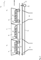
- Figure 2 shows the section of a travelling grate chain 1 which is depicted by way of example with two adjacent wind boxes 41 and 43 and three pallet cars 3 1 , 3 2 and 3 3 .
- the three pallet cars 3 1 , 3 2 and 3 3 each comprise a frame 30 which consists of two end pieces 33 extending in its largest extent in x-direction and which contains preferably five crossbars 32 being arranged across thereto and being fixed at the end pieces 33 and extending in their largest extent in y-direction.
- the grate rods 35 are arranged which gather the filling B of the pallet car.
- the three pallet cars 3 1 , 3 2 and 3 3 pass the wind box 41 and the wind box 43. Extending over both wind boxes 41 and 43 a sealing box 50 is arranged.
- the sealing box 50 is filled with liquid.
- the pallet cars 3 1 , 3 2 and 3 3 each comprises a sealing blade 60, which is shown only for pallet car 3 2 .
- Sealing blades 60 are mounted flush, e.g. at the frame of the pallet cars 3 1 , 3 2 and 3 3 , preferably at the sealing tracks, and each extend over the whole extent of the pallet cars 3 1 , 3 2 and 3 3 in x-direction. As shown, the sealing blades 60 immerse into the sealing box 50.
- liquid can be re-filled into sealing box 50 while it is withdrawn via discharging conduit 72. Thereby, liquid can be recirculated to avoid overheating. It is also possible to re-fill liquid and/or to use a buffer system (not shown).
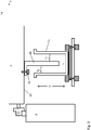
- FIG. 3 shows the sealing box 50 in more detail.
- the sealing blade 60 is mounted on the frame 30 of pellet car 3 (only indicated in fig. 3 ), whereby the sealing blade 60 is formed as an L-profile. Its shorter side is fixed with screw 61 on frame 30 of the pellet car 3 2 .
- Sealing box 50 with height H is filled with liquid L with two levels L 1 and L 2 .
- Level L 1 is found next to the ambient while Level L 2 is developed on the inside of the furnace, preferably sealed in moving direction by two sealing boxes 60 and orthogonal to the moving direction by sealing bars also mounted on the pallet cars 3.
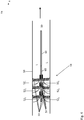
- Fig. 4 shows an entry or an exit zone 51 of a sealing box 50 in x-y perspective. Its assembly is composed by multiples sealing leaves 52 1 , 52 2 , and 52 3 . Preferably these sealing leaves 52 1 , 52 2 , and 52 3 are arranged symmetrical to each other. Also, it is preferred that the sealing leaves 52 1 , 52 2 , and 52 3 features holder polymers 54 on the side which can be pressed on sealing blade 60-
- the sealing leaves 52 1 , 52 2 , and 52 3 are made out soft material of flexible steel pressed against the sealing bar, preferably using springs 53. So they retain the sealing liquid L and avoid that it is poured out of the sealing box 50, since they act as barriers for the liquid at the ending and entrance of the plant length by being pressed against sealing blade 60
Landscapes
- Engineering & Computer Science (AREA)
- Mechanical Engineering (AREA)
- General Engineering & Computer Science (AREA)
- Chemical & Material Sciences (AREA)
- Manufacturing & Machinery (AREA)
- General Life Sciences & Earth Sciences (AREA)
- Geochemistry & Mineralogy (AREA)
- Geology (AREA)
- Environmental & Geological Engineering (AREA)
- Life Sciences & Earth Sciences (AREA)
- Materials Engineering (AREA)
- Metallurgy (AREA)
- Organic Chemistry (AREA)
- Manufacture And Refinement Of Metals (AREA)
- Furnace Details (AREA)
- Processing Of Solid Wastes (AREA)
- Chain Conveyers (AREA)
Claims (13)
- Vorrichtung zur thermischen Behandlung von Schüttgut, mit einer in Bewegungsrichtung umlaufenden Wanderrostkette, bestehend aus einem endlosen Wanderrost (1) mit beweglichen Gliedern, einer Vielzahl von Rostwagen (3), jeder bestehend aus einem Rahmen (30) mit Endstücken (33), an denen Laufräder (31) befestigt sind, und auf Querträgern (32) angeordneten Roststäben (35), und mit Windkästen (41, 43), die so angeordnet sind, dass aus mindestens einem Windkasten (41, 43) Gas durch die Rostwägen (3) und deren Roststäbe (35) von oder in die Windkästen (41, 43) strömt, wobei an jedem Rostwagen (3) des Wanderrostes (1) mindestens je ein Dichtungsflügel (60) parallel zur Fahrtrichtung und bündig mit dem Rostwagen (3) montiert ist, dass in mindestens einem Abschnitt des Wanderrostes (1) parallel zur Bewegungsrichtung mindestens ein Dichtungskasten (50) vorgesehen ist, und dass in den mindestens einen Dichtungskasten (50) ein flüssiges Medium eingefüllt ist, wobei der Dichtungskasten (50) so angeordnet ist, dass das Dichtungsblatt (60) im Betrieb in die Flüssigkeit (L) eintaucht, dadurch gekennzeichnet, dass das Dichtungsblatt (60) in einer Eintrittszone (51) in die Flüssigkeit im Dichtungskasten (50) eintaucht und in einer Austrittszone (51) aus dieser austritt, wobei die Eintritts- und die Austrittszone (51) Dichtungsblätter (521, 522, 523) aufweisen, die mit Federn (53) gegen das Dichtungsblatt (60) gedrückt werden können.
- Vorrichtung nach Anspruch 1, dadurch gekennzeichnet, dass der Dichtungskasten (50) ein u-Profil aufweist.
- Vorrichtung nach einem der vorhergehenden Ansprüche, dadurch gekennzeichnet, dass die Flüssigkeit (L) Wasser oder Kombinationen aus zwei oder drei verschiedenen Flüssigkeiten ist.
- Vorrichtung nach Anspruch 3, dadurch gekennzeichnet, dass der Dichtungskasten (50) eine Höhe (H) aufweist, die höher ist als die Summe aus dem Flüssigkeitsniveau (L1, L2) und A, wobei A definiert ist als

- Vorrichtung nach Anspruch 3 oder 4, dadurch gekennzeichnet, dass der Dichtungskasten (50) so ausgebildet ist, dass der Flüssigkeitsspiegel unter Umgebungsbedingungen eine Höhe (H) aufweist, die höher ist als die Differenz des Flüssigkeitsspiegels (L1, L2) minus A, wobei A definiert ist als

- Vorrichtung nach einem der vorhergehenden Ansprüche, dadurch gekennzeichnet, dass sich das Dichtungsblatt (60) über die gesamte Länge eines Rostwagens (3) von einem Endstück (33) bis zum anderen Endstück (33) erstreckt.
- Vorrichtung nach einem der vorhergehenden Ansprüche, dadurch gekennzeichnet, dass das Dichtungsblatt (60) an den Rahmen (30) der Rostwagen (3) verschraubt ist.
- Vorrichtung nach einem der vorhergehenden Ansprüche, dadurch gekennzeichnet, dass sich der Dichtungskasten (50) über mindestens zwei Windkästen (41, 43) erstreckt.
- Vorrichtung nach einem der Ansprüche 1 bis 7, dadurch gekennzeichnet, dass sich der Dichtungskasten (50) über alle Windkästen (41, 43) erstreck
- Vorrichtung nach einem der vorhergehenden Ansprüche, dadurch gekennzeichnet, dass zwei Dichtungskästen (50) gegenüberliegend und parallel zueinander angeordnet sind.
- Vorrichtung nach Anspruch 1 oder 2, dadurch gekennzeichnet, dass die Dichtungsblätter (521, 522, 523) aus flexiblem Stahl gefertigt sind.
- Vorrichtung nach einem der vorhergehenden Ansprüche, dadurch gekennzeichnet, dass eine Pumpe (70), eine Zuleitung (71) zu dem mindestens einen Dichtungskasten (50) und eine Ableitung (72) von dem mindestens einen Dichtungskasten (50) für die Flüssigkeit vorgesehen ist.
- Verfahren zur thermischen Behandlung von Schüttgut, mit einer in Bewegungsrichtung umlaufenden Wanderrostkette, die einen endlosen Wanderrost mit beweglichen Gliedern aufweist, einer Vielzahl von Rostwagen (3), jeder bestehend aus einem Rahmen (30) mit Laufräder (31) und auf Querträgern (32) angeordneten Roststäben (35), und mit Windkästen (41, 43), die so angeordnet sind, dass aus mindestens einem Windkasten (41, 43) Gas durch die Rostwägen (3) und deren Roststäbe (35) von oder in die Windkästen (41, 43) strömt, wobei wenigstens ein Dichtungsflügel (60) an jedem Rostwagen (3) des Wanderrostes (1) parallel zur Fahrtrichtung und bündig mit dem Rostwagen (3) montiert ist, der in eine in wenigstens einen Dichtungskasten eingefüllte Flüssigkeit eintaucht, wobei der Dichtungskasten in mindestens einem Abschnitt des Wanderrostes parallel zur Bewegungsrichtung vorgesehen ist, dadurch gekennzeichnet, dass das Dichtungsblatt (60) in einem Eintrittsbereich (51) in die Flüssigkeit im Dichtungskasten (50) eintaucht und in einem Austrittsbereich (51) aus diesem austritt, wobei der Eintritts- und der Austrittsbereich (51) Dichtungsflügel (521,522,523) aufweisen, die mit Federn (53) gegen das Dichtungsblatt (60) gedrückt werden können.
Applications Claiming Priority (1)
| Application Number | Priority Date | Filing Date | Title |
|---|---|---|---|
| PCT/EP2017/069662 WO2019024995A1 (en) | 2017-08-03 | 2017-08-03 | LONGITUDINAL SEALING SYSTEM FOR WIND BOXES IN ROLLER GRID INSTALLATIONS |
Publications (2)
| Publication Number | Publication Date |
|---|---|
| EP3662219A1 EP3662219A1 (de) | 2020-06-10 |
| EP3662219B1 true EP3662219B1 (de) | 2021-09-29 |
Family
ID=59579620
Family Applications (1)
| Application Number | Title | Priority Date | Filing Date |
|---|---|---|---|
| EP17751067.4A Active EP3662219B1 (de) | 2017-08-03 | 2017-08-03 | Anlage zur längsversiegelung von windkästen in wanderrostanlagen |
Country Status (8)
| Country | Link |
|---|---|
| US (1) | US20200158435A1 (de) |
| EP (1) | EP3662219B1 (de) |
| CN (1) | CN110998205B (de) |
| BR (1) | BR112020001681B1 (de) |
| CA (1) | CA3071201A1 (de) |
| RU (1) | RU2745753C1 (de) |
| UA (1) | UA122760C2 (de) |
| WO (1) | WO2019024995A1 (de) |
Families Citing this family (2)
| Publication number | Priority date | Publication date | Assignee | Title |
|---|---|---|---|---|
| CN112964070A (zh) * | 2021-02-01 | 2021-06-15 | 中国科学院包头稀土研发中心 | 可基于h钢轨道运行的移动小车及稀土电解自动加料装置 |
| CN113091460A (zh) * | 2021-04-23 | 2021-07-09 | 张家港宏昌钢板有限公司 | 一种烧结机余热监控调节方法 |
Family Cites Families (16)
| Publication number | Priority date | Publication date | Assignee | Title |
|---|---|---|---|---|
| US2800319A (en) * | 1954-10-08 | 1957-07-23 | William M Duncan | Apparatus for heat treating ore |
| US2825550A (en) * | 1955-12-06 | 1958-03-04 | Mcdowell Company Inc | Wind box sealing construction for sintering machines |
| US3589691A (en) * | 1968-10-07 | 1971-06-29 | Mckee & Co Arthur G | Treatment of material on a moving support |
| FR2184445B1 (de) * | 1972-05-17 | 1977-08-19 | Creusot Loire | |
| US3907260A (en) * | 1974-01-23 | 1975-09-23 | Fuel Equipment Co Inc | Apparatus and method for preheating refractory lined ladles |
| DE3433043A1 (de) * | 1984-09-08 | 1986-03-20 | Metallgesellschaft Ag, 6000 Frankfurt | Verfahren zur thermischen behandlung von stueckigen oder agglomerierten materialien auf einem wanderrost |
| CN1248693A (zh) * | 1999-09-09 | 2000-03-29 | 燕山大学 | 烧结机非接触式磁性液体密封装置 |
| DE102011016467B4 (de) * | 2011-04-08 | 2013-05-23 | Outotec Oyj | Rostwagen-Wechselvorrichtung |
| JP5789883B2 (ja) * | 2011-12-05 | 2015-10-07 | Primetals Technologies Japan株式会社 | 部分還元鉄製造方法および部分還元鉄製造装置 |
| RU126440U1 (ru) * | 2012-10-08 | 2013-03-27 | Открытое акционерное общество "Уральский завод тяжелого машиностроения" | Спекательная тележка |
| CN104704310B (zh) * | 2012-10-08 | 2016-10-05 | 奥图泰(芬兰)公司 | 用于散装材料的热处理的机器 |
| RU139691U1 (ru) * | 2013-05-07 | 2014-04-20 | Открытое акционерное общество "Новолипецкий металлургический комбинат" | Агломерационная машина |
| CN104457257B (zh) * | 2014-11-27 | 2016-06-01 | 攀钢集团攀枝花钢钒有限公司 | 烧结机台车底部两侧密封结构 |
| DE102015121829A1 (de) * | 2015-12-15 | 2017-06-22 | Outotec (Finland) Oy | Rostwagen zum Transport von Schüttgut für eine thermische Behandlung |
| DE102016102957A1 (de) * | 2016-02-19 | 2017-08-24 | Outotec (Finland) Oy | Verfahren und Vorrichtung zur Beschickung von Rostwagen eines Wanderrostes zur thermischen Behandlung von Schüttgütern |
| DE202016008145U1 (de) * | 2016-03-15 | 2017-04-04 | Outotec (Finland) Oy | Vorrichtung für die Abdichtung zwischen Windkästen unterschiedlichen Drucks in Wanderrostanlagen |
-
2017
- 2017-08-03 CA CA3071201A patent/CA3071201A1/en active Pending
- 2017-08-03 RU RU2020103565A patent/RU2745753C1/ru active
- 2017-08-03 UA UAA202000423A patent/UA122760C2/uk unknown
- 2017-08-03 EP EP17751067.4A patent/EP3662219B1/de active Active
- 2017-08-03 WO PCT/EP2017/069662 patent/WO2019024995A1/en not_active Ceased
- 2017-08-03 CN CN201780093575.4A patent/CN110998205B/zh active Active
- 2017-08-03 BR BR112020001681-0A patent/BR112020001681B1/pt active IP Right Grant
-
2020
- 2020-01-27 US US16/752,764 patent/US20200158435A1/en not_active Abandoned
Also Published As
| Publication number | Publication date |
|---|---|
| UA122760C2 (uk) | 2020-12-28 |
| BR112020001681A2 (pt) | 2020-07-21 |
| CN110998205A (zh) | 2020-04-10 |
| US20200158435A1 (en) | 2020-05-21 |
| EP3662219A1 (de) | 2020-06-10 |
| CN110998205B (zh) | 2021-10-01 |
| RU2745753C1 (ru) | 2021-03-31 |
| BR112020001681B1 (pt) | 2022-06-14 |
| CA3071201A1 (en) | 2019-02-07 |
| WO2019024995A1 (en) | 2019-02-07 |
Similar Documents
| Publication | Publication Date | Title |
|---|---|---|
| KR20060011990A (ko) | 벌크 재료층을 처리하기 위한 방법 및 장치 | |
| CA2885219C (en) | Machine for the thermal treatment of bulk material | |
| CN203080030U (zh) | 一种环式焙烧机 | |
| US20200158435A1 (en) | Facility for longitudinal sealing up wind boxes in travelling grate facilities | |
| WO2006107332A2 (en) | Linear hearth furnace system and methods regarding same | |
| WO2018065521A1 (en) | Method and device for uniformly feeding a continuous conveyor | |
| CN104428592B (zh) | 用于干式运送炉渣及/或异源材料的设备 | |
| JP5009150B2 (ja) | 冷却したい熱いバラ積み材料を冷却するためのバラ積み材料冷却器 | |
| KR101921940B1 (ko) | 통기성 측정기 및 소결 장치 | |
| US3887064A (en) | Walking beam conveyor in a furnace | |
| US3358385A (en) | Reciprocating grate conveyor with side wall damage preventing means | |
| CN103003206B (zh) | 用于改进熔化过程的方法和装置 | |
| US3137398A (en) | Apparatus for feeding pellets | |
| US3866673A (en) | Heat exchanger for cooling ore cinders | |
| EP0039530B1 (de) | Plattenbandförderer | |
| US3968889A (en) | Conveyor for transporting workpieces | |
| US2878009A (en) | Sinter cooling machines | |
| RU2816886C1 (ru) | Устройство и способ предварительного нагрева и подачи металлической шихты в плавильную печь | |
| US3358981A (en) | Spillage chute for traveling grate machine | |
| RU2795305C1 (ru) | Комплекс для проведения нормализации крупного вагонного литья и закалки с последующим отпуском среднего вагонного литья | |
| US1799956A (en) | Material conveyer for furnaces | |
| US1167118A (en) | Horizontal mechanical furnace for roasting. | |
| Mayr et al. | Handling Hot Sinter at the Watenstedt Sinter Plant | |
| US845217A (en) | Means for loading and unloading coal and other minerals. | |
| CN119953904A (zh) | 一种料仓烟尘随动型封盖装置及工作方法 |
Legal Events
| Date | Code | Title | Description |
|---|---|---|---|
| STAA | Information on the status of an ep patent application or granted ep patent |
Free format text: STATUS: UNKNOWN |
|
| STAA | Information on the status of an ep patent application or granted ep patent |
Free format text: STATUS: THE INTERNATIONAL PUBLICATION HAS BEEN MADE |
|
| PUAI | Public reference made under article 153(3) epc to a published international application that has entered the european phase |
Free format text: ORIGINAL CODE: 0009012 |
|
| STAA | Information on the status of an ep patent application or granted ep patent |
Free format text: STATUS: REQUEST FOR EXAMINATION WAS MADE |
|
| 17P | Request for examination filed |
Effective date: 20200120 |
|
| AK | Designated contracting states |
Kind code of ref document: A1 Designated state(s): AL AT BE BG CH CY CZ DE DK EE ES FI FR GB GR HR HU IE IS IT LI LT LU LV MC MK MT NL NO PL PT RO RS SE SI SK SM TR |
|
| AX | Request for extension of the european patent |
Extension state: BA ME |
|
| RIN1 | Information on inventor provided before grant (corrected) |
Inventor name: ATHAYDE, MAYCON Inventor name: SALAGUNDI, BASAVAN GOUD |
|
| RIN1 | Information on inventor provided before grant (corrected) |
Inventor name: ATHAYDE, MAYCON Inventor name: SALAGUNDI, BASAVAN GOUD |
|
| DAV | Request for validation of the european patent (deleted) | ||
| DAX | Request for extension of the european patent (deleted) | ||
| GRAP | Despatch of communication of intention to grant a patent |
Free format text: ORIGINAL CODE: EPIDOSNIGR1 |
|
| STAA | Information on the status of an ep patent application or granted ep patent |
Free format text: STATUS: GRANT OF PATENT IS INTENDED |
|
| INTG | Intention to grant announced |
Effective date: 20210318 |
|
| GRAS | Grant fee paid |
Free format text: ORIGINAL CODE: EPIDOSNIGR3 |
|
| GRAA | (expected) grant |
Free format text: ORIGINAL CODE: 0009210 |
|
| STAA | Information on the status of an ep patent application or granted ep patent |
Free format text: STATUS: THE PATENT HAS BEEN GRANTED |
|
| AK | Designated contracting states |
Kind code of ref document: B1 Designated state(s): AL AT BE BG CH CY CZ DE DK EE ES FI FR GB GR HR HU IE IS IT LI LT LU LV MC MK MT NL NO PL PT RO RS SE SI SK SM TR |
|
| REG | Reference to a national code |
Ref country code: GB Ref legal event code: FG4D |
|
| REG | Reference to a national code |
Ref country code: CH Ref legal event code: EP Ref country code: AT Ref legal event code: REF Ref document number: 1434554 Country of ref document: AT Kind code of ref document: T Effective date: 20211015 |
|
| REG | Reference to a national code |
Ref country code: DE Ref legal event code: R096 Ref document number: 602017046779 Country of ref document: DE |
|
| REG | Reference to a national code |
Ref country code: IE Ref legal event code: FG4D |
|
| REG | Reference to a national code |
Ref country code: FI Ref legal event code: FGE |
|
| REG | Reference to a national code |
Ref country code: NL Ref legal event code: FP |
|
| REG | Reference to a national code |
Ref country code: LT Ref legal event code: MG9D |
|
| REG | Reference to a national code |
Ref country code: SE Ref legal event code: TRGR |
|
| PG25 | Lapsed in a contracting state [announced via postgrant information from national office to epo] |
Ref country code: HR Free format text: LAPSE BECAUSE OF FAILURE TO SUBMIT A TRANSLATION OF THE DESCRIPTION OR TO PAY THE FEE WITHIN THE PRESCRIBED TIME-LIMIT Effective date: 20210929 Ref country code: RS Free format text: LAPSE BECAUSE OF FAILURE TO SUBMIT A TRANSLATION OF THE DESCRIPTION OR TO PAY THE FEE WITHIN THE PRESCRIBED TIME-LIMIT Effective date: 20210929 Ref country code: NO Free format text: LAPSE BECAUSE OF FAILURE TO SUBMIT A TRANSLATION OF THE DESCRIPTION OR TO PAY THE FEE WITHIN THE PRESCRIBED TIME-LIMIT Effective date: 20211229 Ref country code: LT Free format text: LAPSE BECAUSE OF FAILURE TO SUBMIT A TRANSLATION OF THE DESCRIPTION OR TO PAY THE FEE WITHIN THE PRESCRIBED TIME-LIMIT Effective date: 20210929 Ref country code: BG Free format text: LAPSE BECAUSE OF FAILURE TO SUBMIT A TRANSLATION OF THE DESCRIPTION OR TO PAY THE FEE WITHIN THE PRESCRIBED TIME-LIMIT Effective date: 20211229 |
|
| REG | Reference to a national code |
Ref country code: AT Ref legal event code: MK05 Ref document number: 1434554 Country of ref document: AT Kind code of ref document: T Effective date: 20210929 |
|
| PG25 | Lapsed in a contracting state [announced via postgrant information from national office to epo] |
Ref country code: LV Free format text: LAPSE BECAUSE OF FAILURE TO SUBMIT A TRANSLATION OF THE DESCRIPTION OR TO PAY THE FEE WITHIN THE PRESCRIBED TIME-LIMIT Effective date: 20210929 Ref country code: GR Free format text: LAPSE BECAUSE OF FAILURE TO SUBMIT A TRANSLATION OF THE DESCRIPTION OR TO PAY THE FEE WITHIN THE PRESCRIBED TIME-LIMIT Effective date: 20211230 |
|
| PG25 | Lapsed in a contracting state [announced via postgrant information from national office to epo] |
Ref country code: AT Free format text: LAPSE BECAUSE OF FAILURE TO SUBMIT A TRANSLATION OF THE DESCRIPTION OR TO PAY THE FEE WITHIN THE PRESCRIBED TIME-LIMIT Effective date: 20210929 |
|
| PG25 | Lapsed in a contracting state [announced via postgrant information from national office to epo] |
Ref country code: IS Free format text: LAPSE BECAUSE OF FAILURE TO SUBMIT A TRANSLATION OF THE DESCRIPTION OR TO PAY THE FEE WITHIN THE PRESCRIBED TIME-LIMIT Effective date: 20220129 Ref country code: SK Free format text: LAPSE BECAUSE OF FAILURE TO SUBMIT A TRANSLATION OF THE DESCRIPTION OR TO PAY THE FEE WITHIN THE PRESCRIBED TIME-LIMIT Effective date: 20210929 Ref country code: RO Free format text: LAPSE BECAUSE OF FAILURE TO SUBMIT A TRANSLATION OF THE DESCRIPTION OR TO PAY THE FEE WITHIN THE PRESCRIBED TIME-LIMIT Effective date: 20210929 Ref country code: PT Free format text: LAPSE BECAUSE OF FAILURE TO SUBMIT A TRANSLATION OF THE DESCRIPTION OR TO PAY THE FEE WITHIN THE PRESCRIBED TIME-LIMIT Effective date: 20220131 Ref country code: PL Free format text: LAPSE BECAUSE OF FAILURE TO SUBMIT A TRANSLATION OF THE DESCRIPTION OR TO PAY THE FEE WITHIN THE PRESCRIBED TIME-LIMIT Effective date: 20210929 Ref country code: ES Free format text: LAPSE BECAUSE OF FAILURE TO SUBMIT A TRANSLATION OF THE DESCRIPTION OR TO PAY THE FEE WITHIN THE PRESCRIBED TIME-LIMIT Effective date: 20210929 Ref country code: EE Free format text: LAPSE BECAUSE OF FAILURE TO SUBMIT A TRANSLATION OF THE DESCRIPTION OR TO PAY THE FEE WITHIN THE PRESCRIBED TIME-LIMIT Effective date: 20210929 Ref country code: CZ Free format text: LAPSE BECAUSE OF FAILURE TO SUBMIT A TRANSLATION OF THE DESCRIPTION OR TO PAY THE FEE WITHIN THE PRESCRIBED TIME-LIMIT Effective date: 20210929 Ref country code: AL Free format text: LAPSE BECAUSE OF FAILURE TO SUBMIT A TRANSLATION OF THE DESCRIPTION OR TO PAY THE FEE WITHIN THE PRESCRIBED TIME-LIMIT Effective date: 20210929 |
|
| REG | Reference to a national code |
Ref country code: DE Ref legal event code: R097 Ref document number: 602017046779 Country of ref document: DE |
|
| PG25 | Lapsed in a contracting state [announced via postgrant information from national office to epo] |
Ref country code: DK Free format text: LAPSE BECAUSE OF FAILURE TO SUBMIT A TRANSLATION OF THE DESCRIPTION OR TO PAY THE FEE WITHIN THE PRESCRIBED TIME-LIMIT Effective date: 20210929 |
|
| PLBE | No opposition filed within time limit |
Free format text: ORIGINAL CODE: 0009261 |
|
| STAA | Information on the status of an ep patent application or granted ep patent |
Free format text: STATUS: NO OPPOSITION FILED WITHIN TIME LIMIT |
|
| 26N | No opposition filed |
Effective date: 20220630 |
|
| PG25 | Lapsed in a contracting state [announced via postgrant information from national office to epo] |
Ref country code: SI Free format text: LAPSE BECAUSE OF FAILURE TO SUBMIT A TRANSLATION OF THE DESCRIPTION OR TO PAY THE FEE WITHIN THE PRESCRIBED TIME-LIMIT Effective date: 20210929 |
|
| REG | Reference to a national code |
Ref country code: DE Ref legal event code: R081 Ref document number: 602017046779 Country of ref document: DE Owner name: METSO OUTOTEC FINLAND OY, FI Free format text: FORMER OWNER: OUTOTEC (FINLAND) OY, ESPOO, FI Ref country code: DE Ref legal event code: R081 Ref document number: 602017046779 Country of ref document: DE Owner name: METSO METALS OY, FI Free format text: FORMER OWNER: OUTOTEC (FINLAND) OY, ESPOO, FI |
|
| REG | Reference to a national code |
Ref country code: NL Ref legal event code: PD Owner name: METSO MINERALS OY; FI Free format text: DETAILS ASSIGNMENT: CHANGE OF OWNER(S), MERGE; FORMER OWNER NAME: OUTOTEC (FINLAND) OY Effective date: 20230118 Ref country code: NL Ref legal event code: HC Owner name: METSO OUTOTEC FINLAND OY; FI Free format text: DETAILS ASSIGNMENT: CHANGE OF OWNER(S), CHANGE OF OWNER(S) NAME; FORMER OWNER NAME: METSO MINERALS OY Effective date: 20230118 |
|
| PG25 | Lapsed in a contracting state [announced via postgrant information from national office to epo] |
Ref country code: IT Free format text: LAPSE BECAUSE OF FAILURE TO SUBMIT A TRANSLATION OF THE DESCRIPTION OR TO PAY THE FEE WITHIN THE PRESCRIBED TIME-LIMIT Effective date: 20210929 |
|
| PG25 | Lapsed in a contracting state [announced via postgrant information from national office to epo] |
Ref country code: MC Free format text: LAPSE BECAUSE OF FAILURE TO SUBMIT A TRANSLATION OF THE DESCRIPTION OR TO PAY THE FEE WITHIN THE PRESCRIBED TIME-LIMIT Effective date: 20210929 |
|
| REG | Reference to a national code |
Ref country code: CH Ref legal event code: PL |
|
| GBPC | Gb: european patent ceased through non-payment of renewal fee |
Effective date: 20220803 |
|
| PG25 | Lapsed in a contracting state [announced via postgrant information from national office to epo] |
Ref country code: LU Free format text: LAPSE BECAUSE OF NON-PAYMENT OF DUE FEES Effective date: 20220803 Ref country code: LI Free format text: LAPSE BECAUSE OF NON-PAYMENT OF DUE FEES Effective date: 20220831 Ref country code: CH Free format text: LAPSE BECAUSE OF NON-PAYMENT OF DUE FEES Effective date: 20220831 |
|
| REG | Reference to a national code |
Ref country code: BE Ref legal event code: MM Effective date: 20220831 |
|
| PG25 | Lapsed in a contracting state [announced via postgrant information from national office to epo] |
Ref country code: IE Free format text: LAPSE BECAUSE OF NON-PAYMENT OF DUE FEES Effective date: 20220803 Ref country code: FR Free format text: LAPSE BECAUSE OF NON-PAYMENT OF DUE FEES Effective date: 20220831 |
|
| REG | Reference to a national code |
Ref country code: FI Ref legal event code: PCE Owner name: METSO OUTOTEC FINLAND OY, FI |
|
| PG25 | Lapsed in a contracting state [announced via postgrant information from national office to epo] |
Ref country code: BE Free format text: LAPSE BECAUSE OF NON-PAYMENT OF DUE FEES Effective date: 20220831 |
|
| PG25 | Lapsed in a contracting state [announced via postgrant information from national office to epo] |
Ref country code: GB Free format text: LAPSE BECAUSE OF NON-PAYMENT OF DUE FEES Effective date: 20220803 |
|
| REG | Reference to a national code |
Ref country code: NL Ref legal event code: PD Owner name: METSO OUTOTEC METALS OY; FI Free format text: DETAILS ASSIGNMENT: CHANGE OF OWNER(S), ASSIGNMENT; FORMER OWNER NAME: OUTOTEC (FINLAND) OY Effective date: 20240403 Ref country code: NL Ref legal event code: HC Owner name: METSO METALS OY; FI Free format text: DETAILS ASSIGNMENT: CHANGE OF OWNER(S), CHANGE OF OWNER(S) NAME; FORMER OWNER NAME: METSO OUTOTEC METALS OY Effective date: 20240403 |
|
| PG25 | Lapsed in a contracting state [announced via postgrant information from national office to epo] |
Ref country code: SM Free format text: LAPSE BECAUSE OF FAILURE TO SUBMIT A TRANSLATION OF THE DESCRIPTION OR TO PAY THE FEE WITHIN THE PRESCRIBED TIME-LIMIT Effective date: 20210929 Ref country code: MK Free format text: LAPSE BECAUSE OF FAILURE TO SUBMIT A TRANSLATION OF THE DESCRIPTION OR TO PAY THE FEE WITHIN THE PRESCRIBED TIME-LIMIT Effective date: 20210929 Ref country code: CY Free format text: LAPSE BECAUSE OF FAILURE TO SUBMIT A TRANSLATION OF THE DESCRIPTION OR TO PAY THE FEE WITHIN THE PRESCRIBED TIME-LIMIT Effective date: 20210929 |
|
| REG | Reference to a national code |
Ref country code: FI Ref legal event code: PCE Owner name: METSO METALS OY |
|
| PG25 | Lapsed in a contracting state [announced via postgrant information from national office to epo] |
Ref country code: HU Free format text: LAPSE BECAUSE OF FAILURE TO SUBMIT A TRANSLATION OF THE DESCRIPTION OR TO PAY THE FEE WITHIN THE PRESCRIBED TIME-LIMIT; INVALID AB INITIO Effective date: 20170803 |
|
| REG | Reference to a national code |
Ref country code: DE Ref legal event code: R081 Ref document number: 602017046779 Country of ref document: DE Owner name: METSO METALS OY, FI Free format text: FORMER OWNER: METSO OUTOTEC FINLAND OY, TAMPERE, FI |
|
| PG25 | Lapsed in a contracting state [announced via postgrant information from national office to epo] |
Ref country code: MT Free format text: LAPSE BECAUSE OF FAILURE TO SUBMIT A TRANSLATION OF THE DESCRIPTION OR TO PAY THE FEE WITHIN THE PRESCRIBED TIME-LIMIT Effective date: 20210929 |
|
| PGFP | Annual fee paid to national office [announced via postgrant information from national office to epo] |
Ref country code: NL Payment date: 20250821 Year of fee payment: 9 |
|
| PGFP | Annual fee paid to national office [announced via postgrant information from national office to epo] |
Ref country code: FI Payment date: 20250822 Year of fee payment: 9 |
|
| PGFP | Annual fee paid to national office [announced via postgrant information from national office to epo] |
Ref country code: DE Payment date: 20250820 Year of fee payment: 9 |
|
| PGFP | Annual fee paid to national office [announced via postgrant information from national office to epo] |
Ref country code: SE Payment date: 20250820 Year of fee payment: 9 |
|
| PG25 | Lapsed in a contracting state [announced via postgrant information from national office to epo] |
Ref country code: TR Free format text: LAPSE BECAUSE OF FAILURE TO SUBMIT A TRANSLATION OF THE DESCRIPTION OR TO PAY THE FEE WITHIN THE PRESCRIBED TIME-LIMIT Effective date: 20210929 |